


Table of Contents
- Introduction
- (Un?)Lucky purchase
- Faulty electrolytic capacitors
- Trying to power up the scopemeter
- Fluke 97 DIY Power Plug / Power Adapter
- Battery replacement ?
- Fluke 97 DIY Infrared Cable
- ScopeGrab32 modifications
- Final thoughts
Introduction
I don’t know why I bought this one. Maybe due to its very low price – sold as defective ? Or maybe seeing a Fluke 123 in a local Cashconverters triggered a desire to own a Fluke oscilloscope ?
I skipped the one at Cashconverters. A nasty scratch on the plastic lens put me off. But it triggered something – it felt very robust. I started reading.
For the Fluke 97, the most common problem is the electrolytic capacitors going bad, which, if they don’t impact the Power On, at least one of them may impact the backlight brightness. The video “PE #3 Teardown and Repair of a Fluke 97 Scopemeter” goes a lot more in-depth – a dead IC fails to provide power to the keyboard. Without power for the keyboard circuitry, it will not register that you pushed the On button. To continue, the next hurdle is the battery – most replacements are of a different chemistry than initially designed by Fluke – these aftermarket batteries may not be fully compatible with the trickle charge provided by the device.
(Un?)Lucky purchase
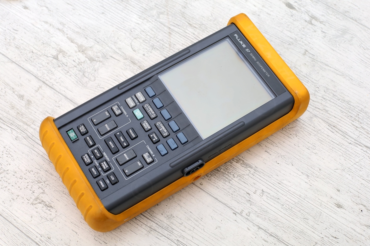
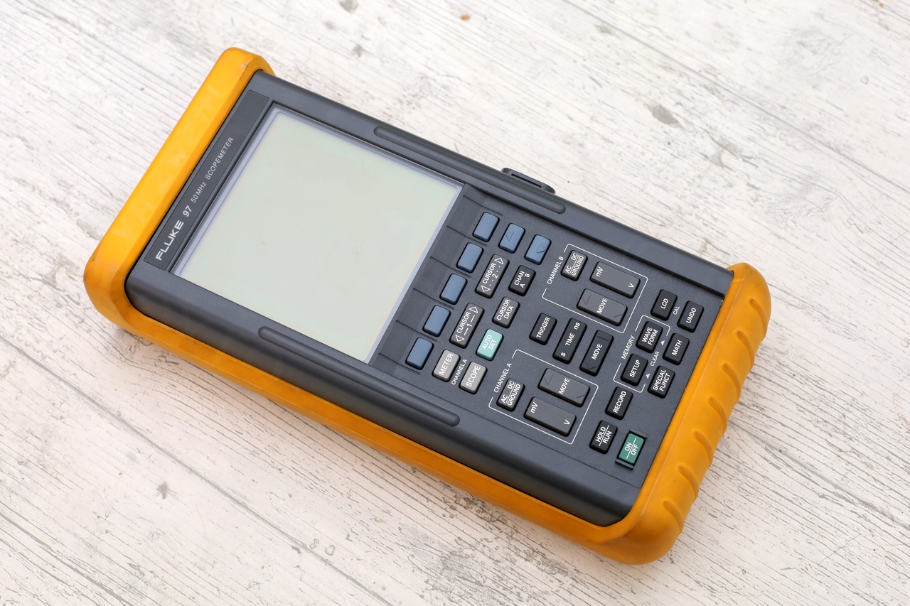
One evening I spot a Fluke 97 Scopemeter described as “does not turn on anymore”. Double the price of EEVBlog’s “50$ oscilloscope” – almost triple with shipping. Still much better than the prices of working ones that were up for sale. Was not willing to pay for a working one and having to (maybe) fix it after a while. Better buying it already broken, at least the price is lower.
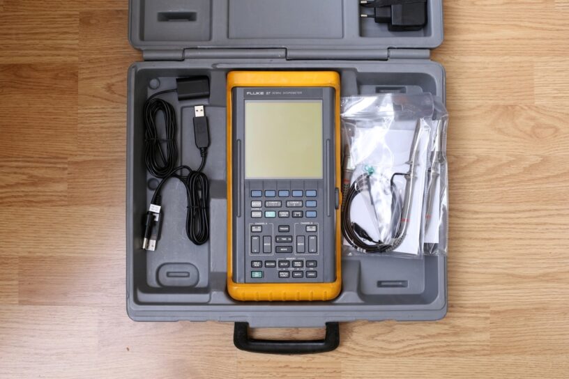
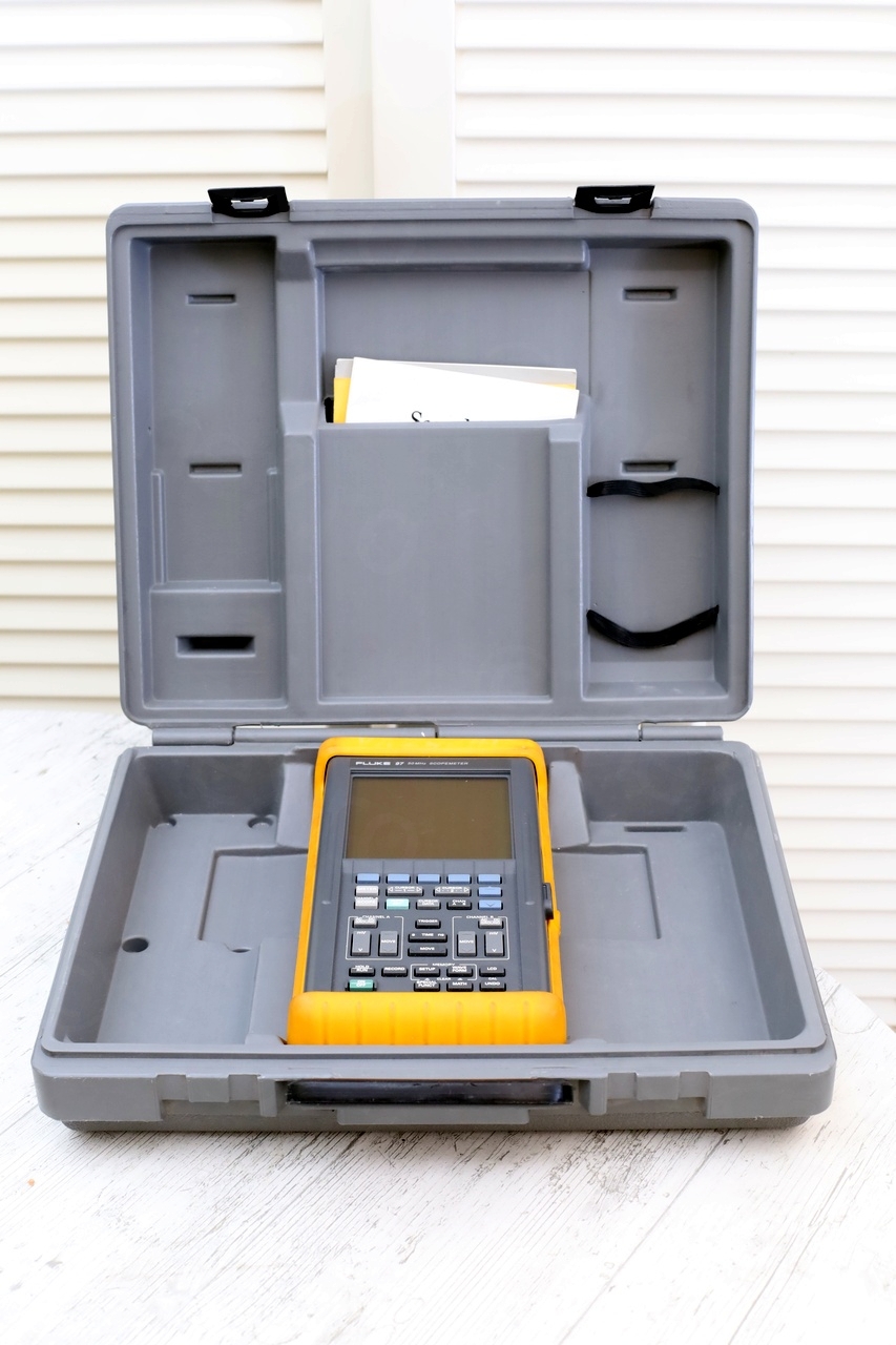
The Ebay announcement was rather lackluster. Scopemeter was sold in its carry case with instructions booklet, but nothing else – no charger, no battery, no probes, no infrared adapter. Oh well, at least if I can’t fix the scope – at least I’m not paying for slack.
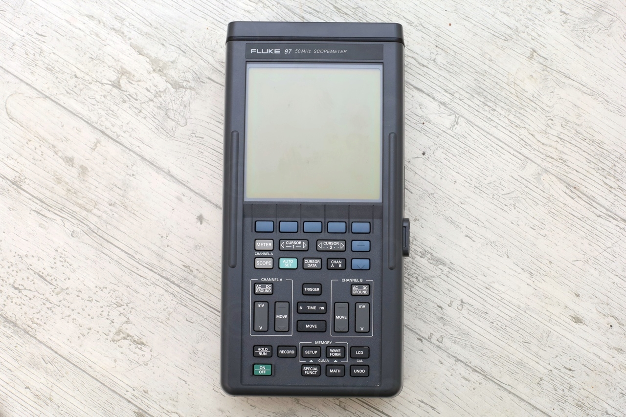
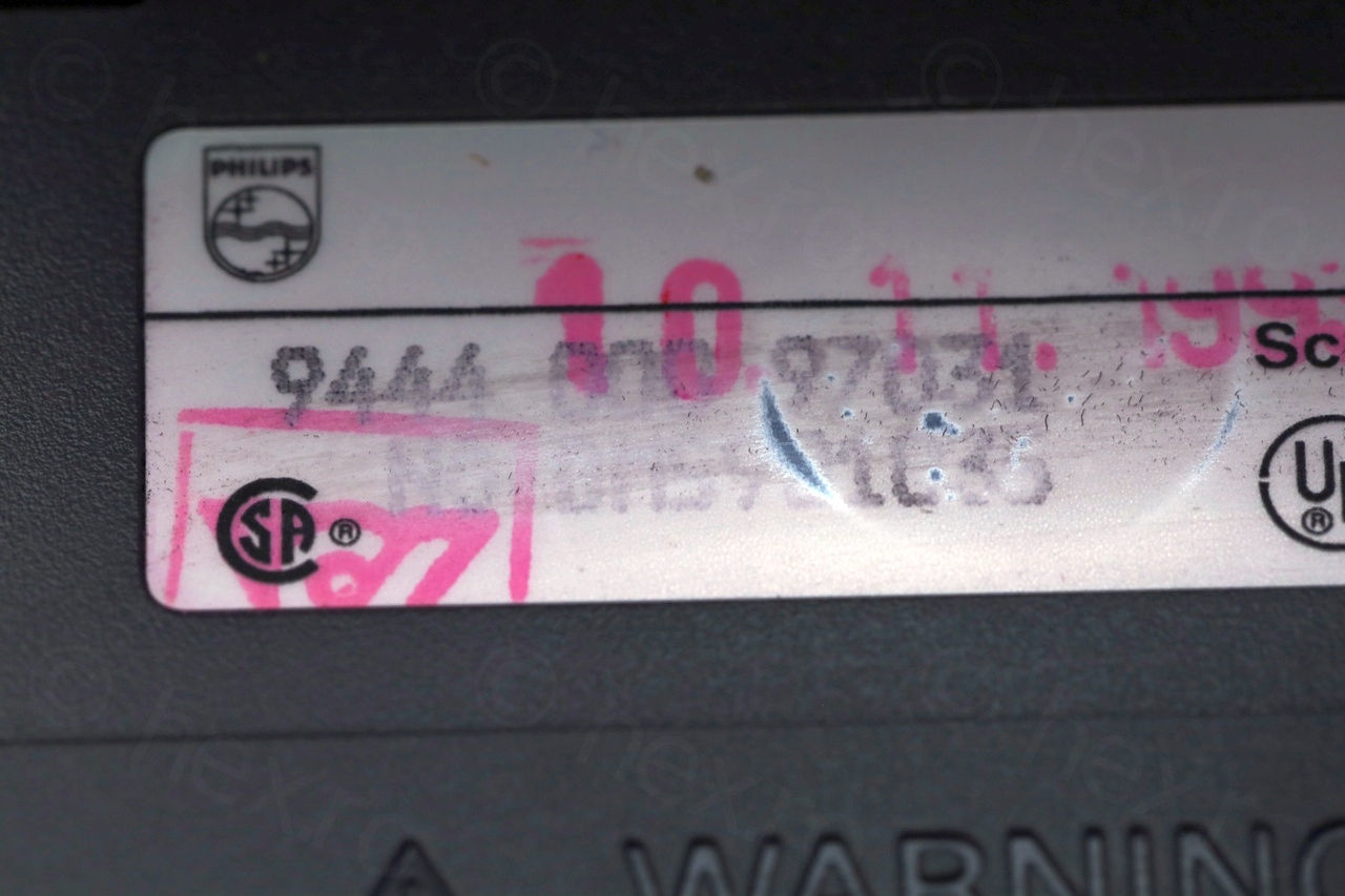
The scope arrived and surprisingly it was in excellent condition, looked much better than seller photos. The holster was intact and not very dirty. There were no scratches on the lens. One small annoyance – somebody tried really hard to remove all history of the meter. Stickers were peeled of. There were eraser marks on the serial number sticker, thankfully they realized and stopped – value is still readable.

Faulty electrolytic capacitors
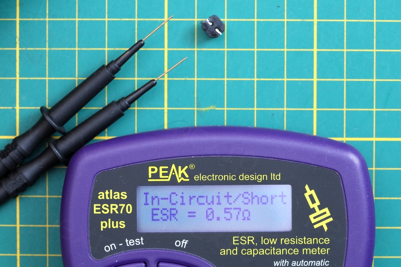
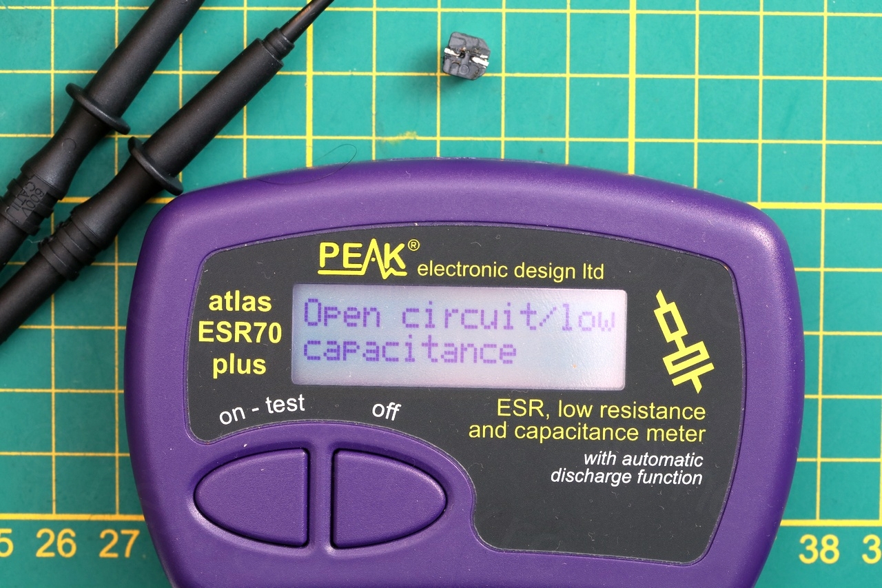
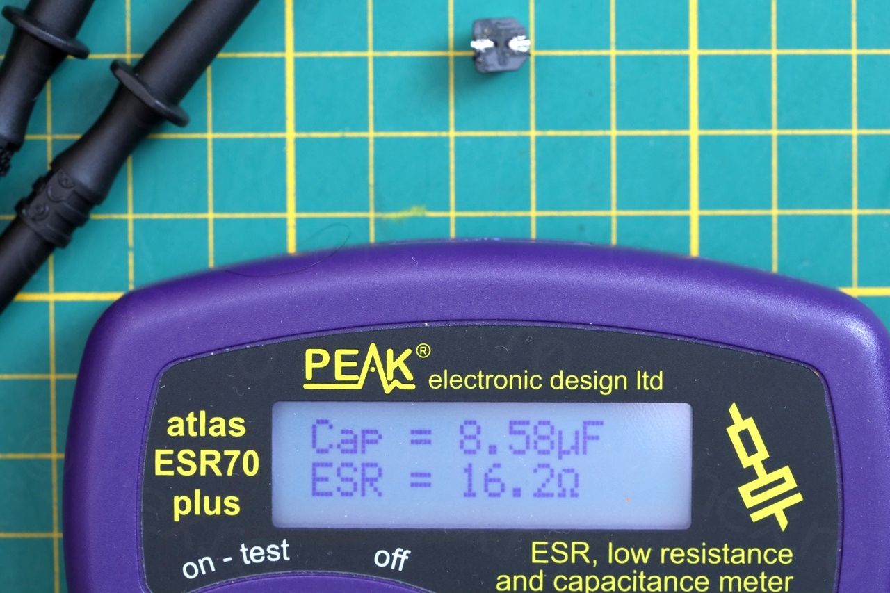
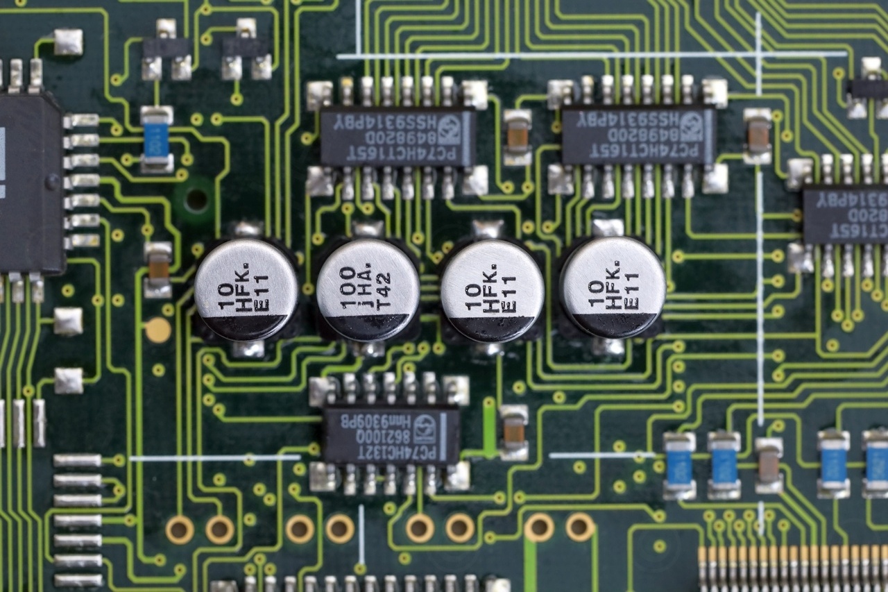
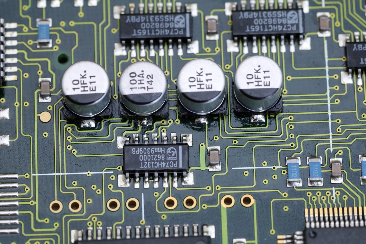
Since the meter was sold as defective, I didn’t even power it up – went straight to check the 4 electrolytic capacitors that many reported as bad. Found that all 4 capacitors have leaked, the second one from the left was the worst – its pad started to lift itself from the board due to corrosion:
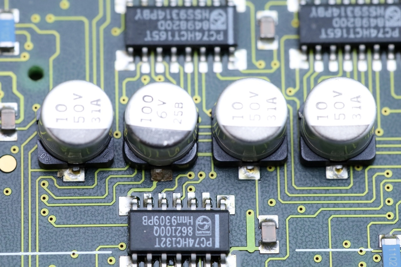
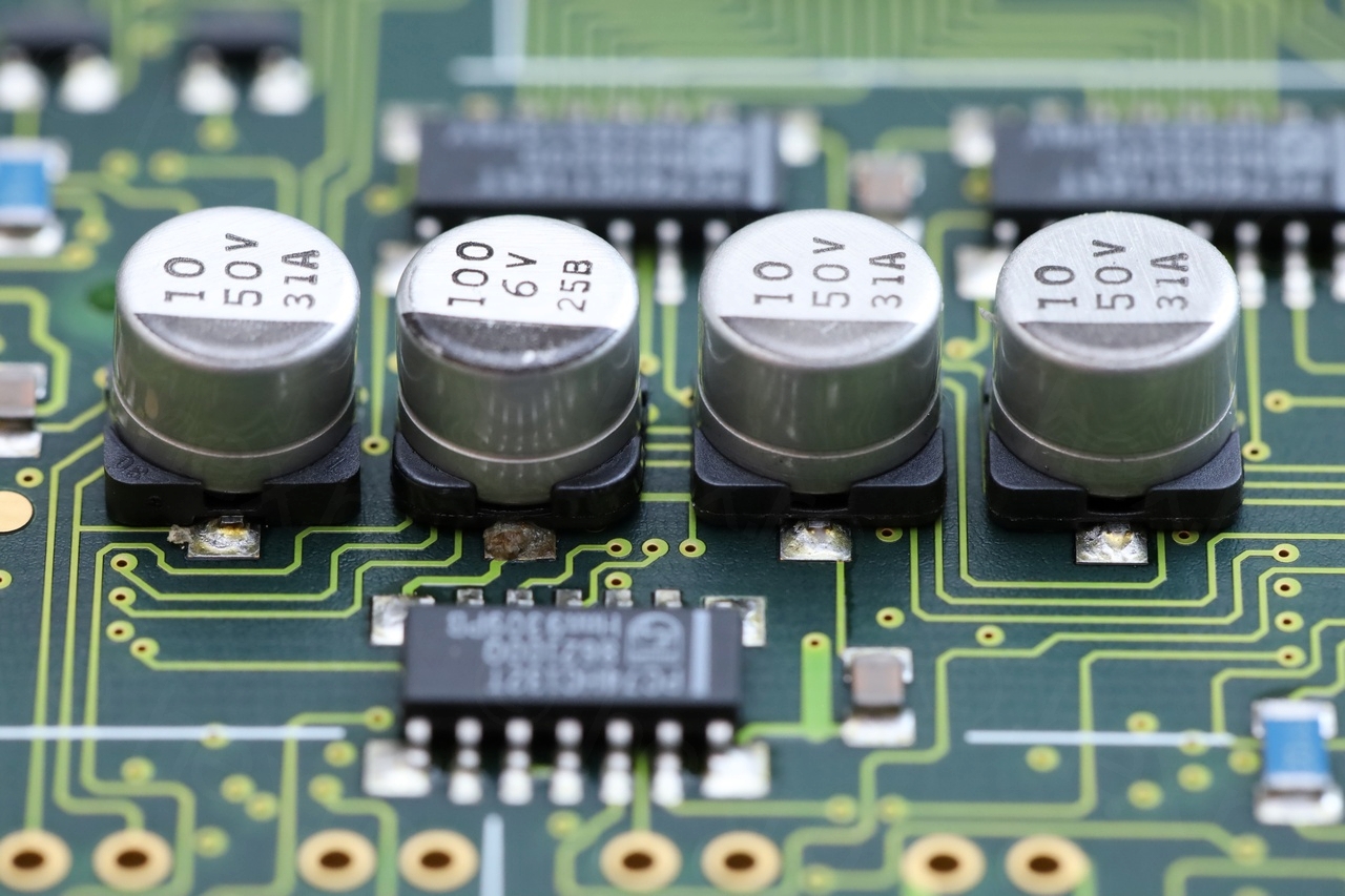
Three of the capacitors are 10µF @ 50V – the second from the left (most corroded) is 100µF @ 6V.

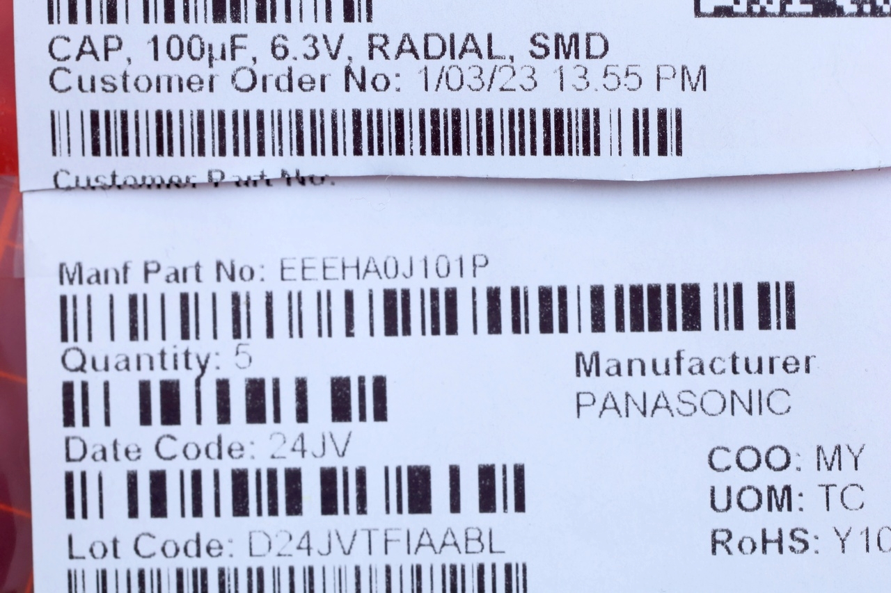
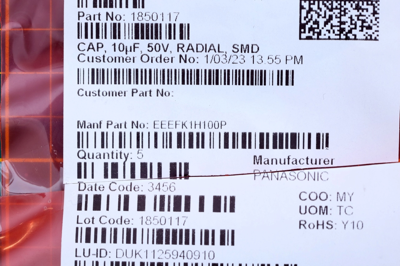
I replaced them with some Panasonic ones, after thoroughly cleaning the pads. I had troubles getting the pad of the second capacitor to take solder, even with copious amount of solder flux. The rest of the pad did take solder but not the corner, thus, I decided not to scratch it and risking more.
Trying to power up the scopemeter
After swapping the capacitors, it was time for the first power up. Ah!
Most aftermarket battery packs for Fluke 97 seem to be of 4.8V kind, but with my DC-DC buck boost convert also set 4.8V, I could not power on the Fluke using via the battery compartment. The oscilloscope would make a high pitch sound, R1416 and T1402 would get hot, but that was it.
It dawned on me that I may be in for a lot more repairs than I was hoping for … but after some educated trial and errors later, I think I have a possible explanation – since I was finally able to power it up.
It seems that Fluke 97 draws a lot of current at current at startup. This is too much draw for the puny DC-DC converter I was using. Its output voltage momentarily sinks below 4V and Fluke 97 won’t have any of this and refuses to start (as if battery is empty).
The way I realized it was letting myself puzzled by how the Fluke’s DC jack is hooked up relative to the battery compartment. Since minimum voltage allowed at the power jack (center negative) is 8V, I disconnected the DC-DC power jack from the battery compartment, upped it to 8V and tried applying power via the DC jack of the scopemeter (center negative). And it worked! There is still a big surge of current, but somehow, at 8V, the small buck boost converter doesn’t sag so quickly and Fluke boots up. Pfaaa!
Fluke 97 DIY Power Plug / Power Adapter
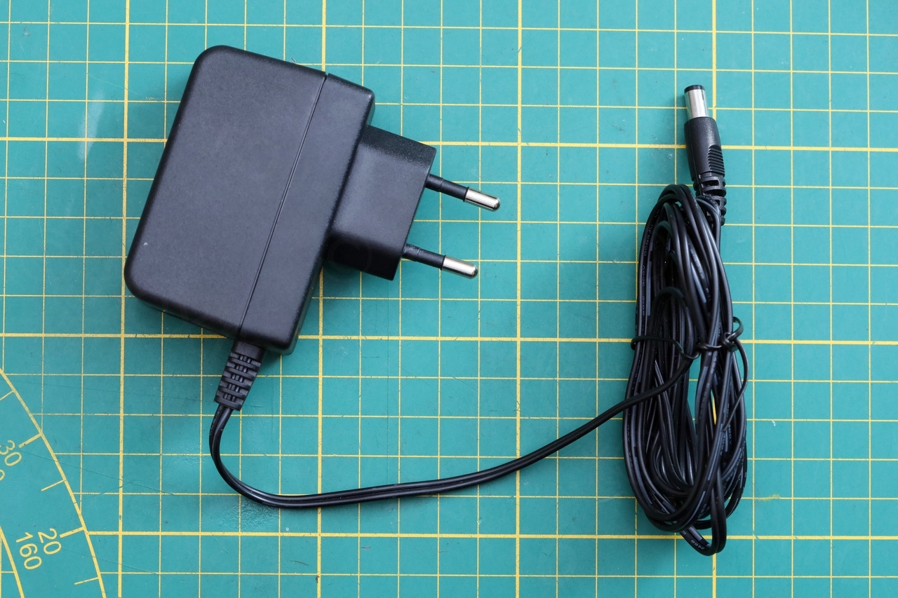
One trouble with the scopemeter is that its DC power plug is sunk deeply inside the body. According to the chapter 2-17 in the manual a DIN 45323 connector is needed. While there are power adapters specifically made for the scopemeter, I have so many power bricks around that I just didn’t want to buy one more. Unfortunatelly all using the standard DC jack which won’t fit.
So where to buy get this mystical DIN 45323 plug from ? If I could get one, I would take a standard 12V power adapter and cut its plug off, wire the new plug correctly (center negative) and that would be it.
I found a seller in Germany but he wasn’t shipping internationally, I asked if he is willing to ship to Belgium and he was kind enough to reply that he isn’t. None of the other online shops were selling it. Hmmm..
I found several mentions online where people were ‘shaving’ a normal DC power plug to get it to slide in deep enough into the meter. So be it, I’ll go DIY route.
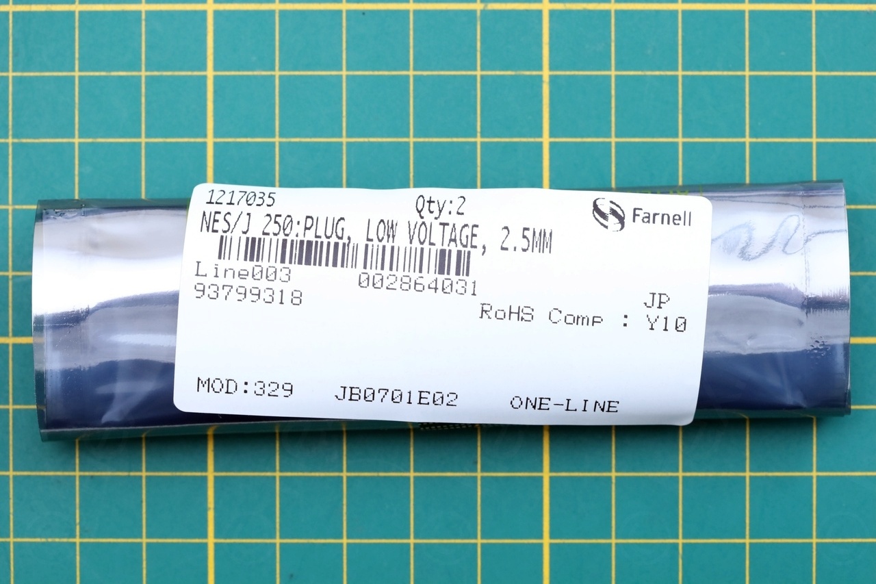
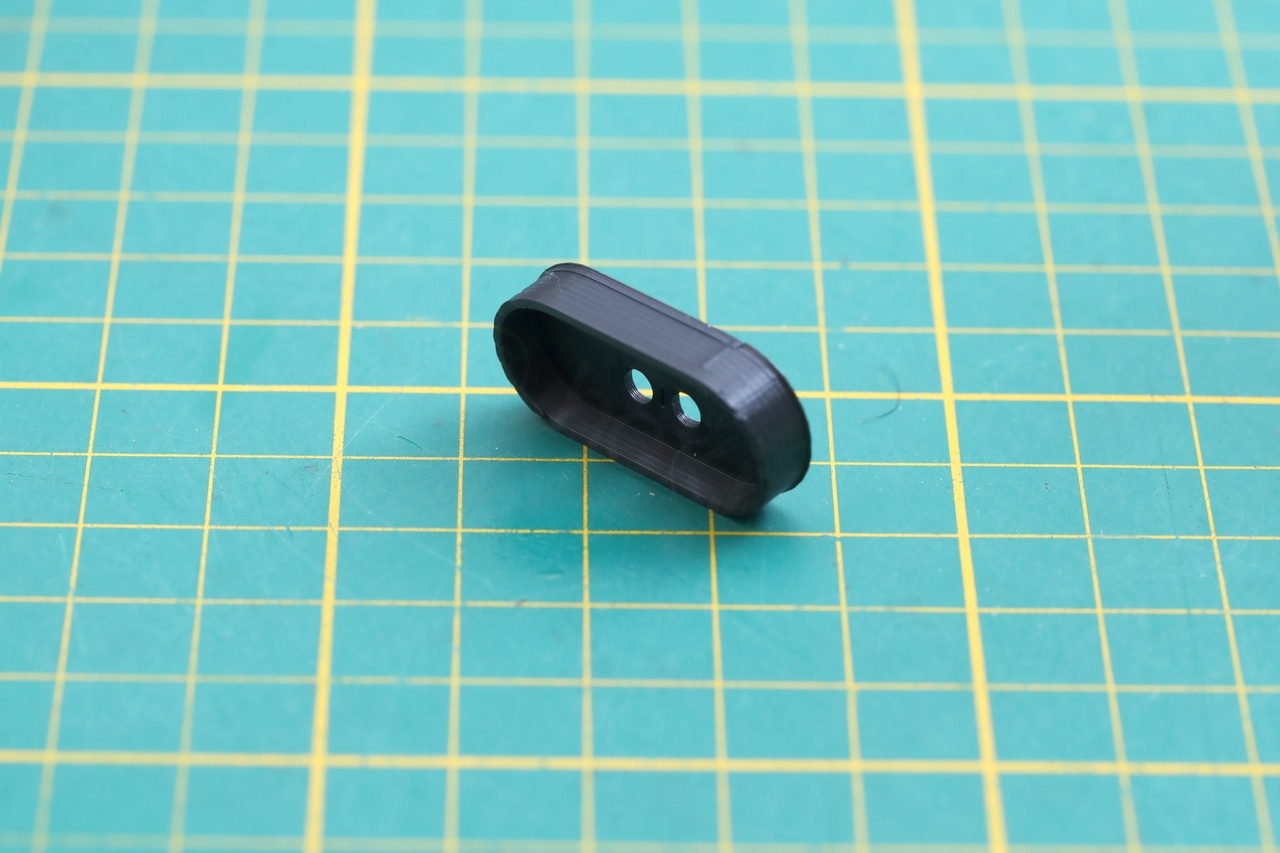
I found a thin DC plug ( NES/J 250 Lumberg, 1A rated) which didn’t seem to need shaving and was a bit longer than the standard plugs. It did slide in properly into the meter, but it was leaving me only few mm where I could grab it from and pull it out. I had an idea to design an extender:
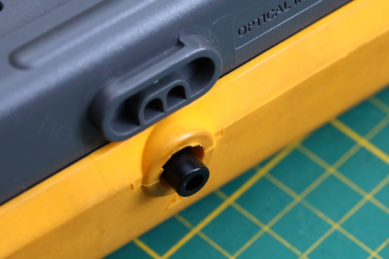
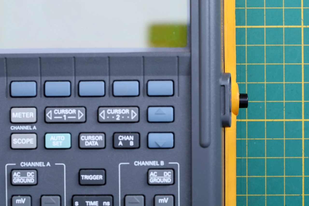

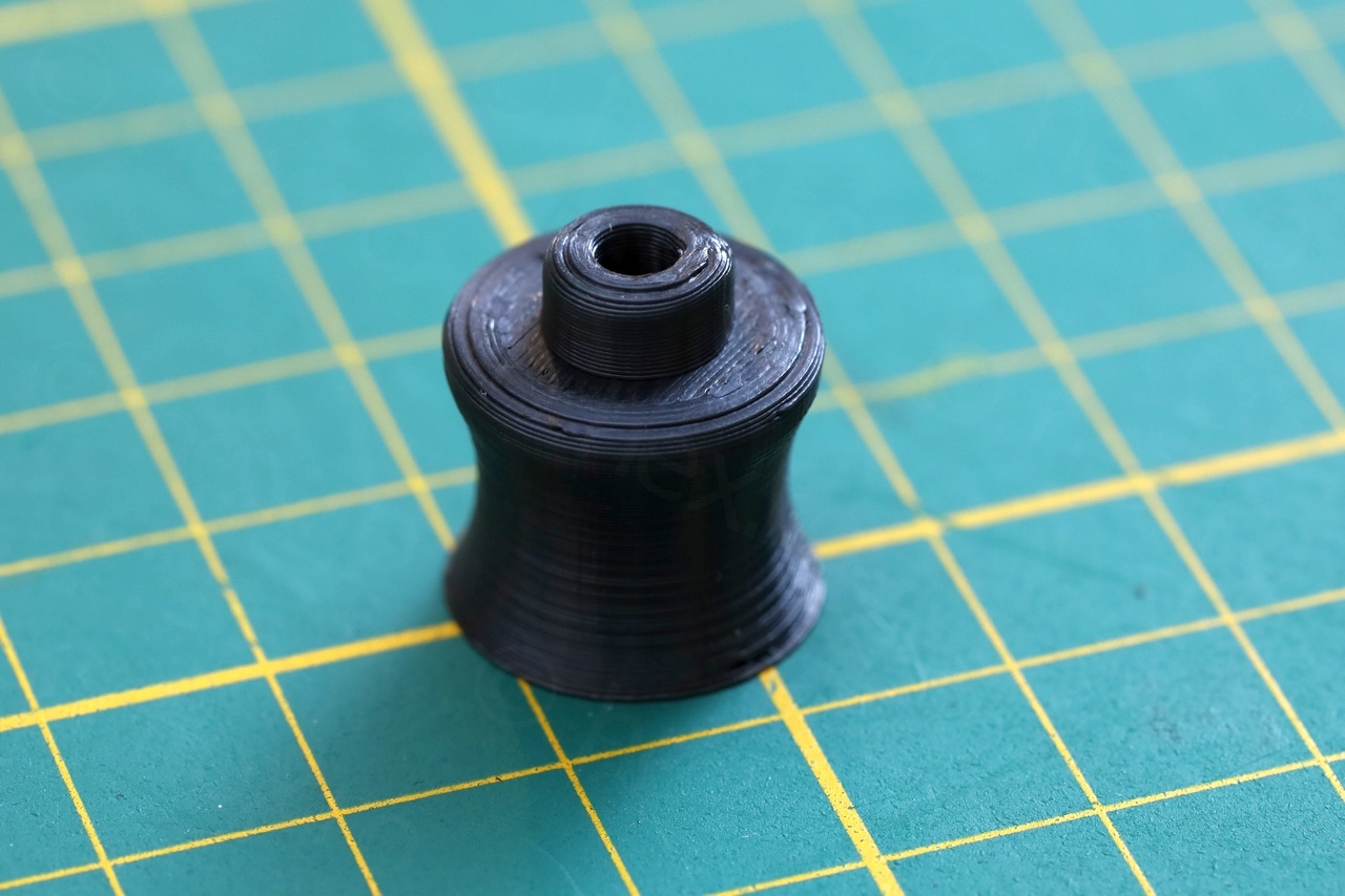
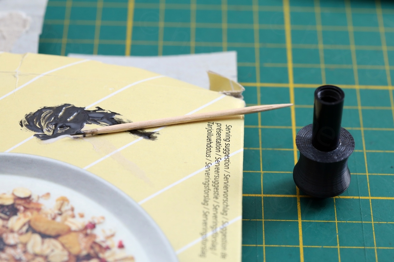
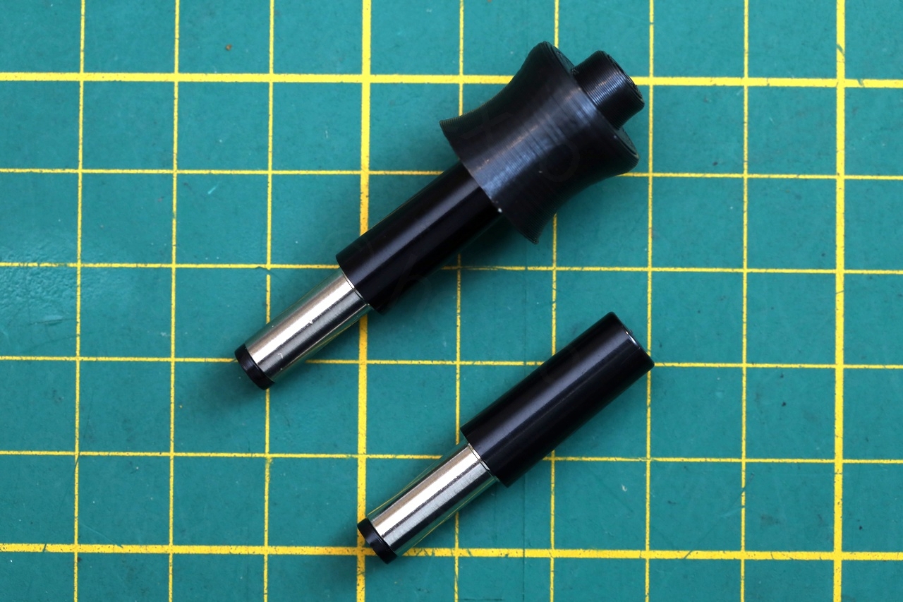
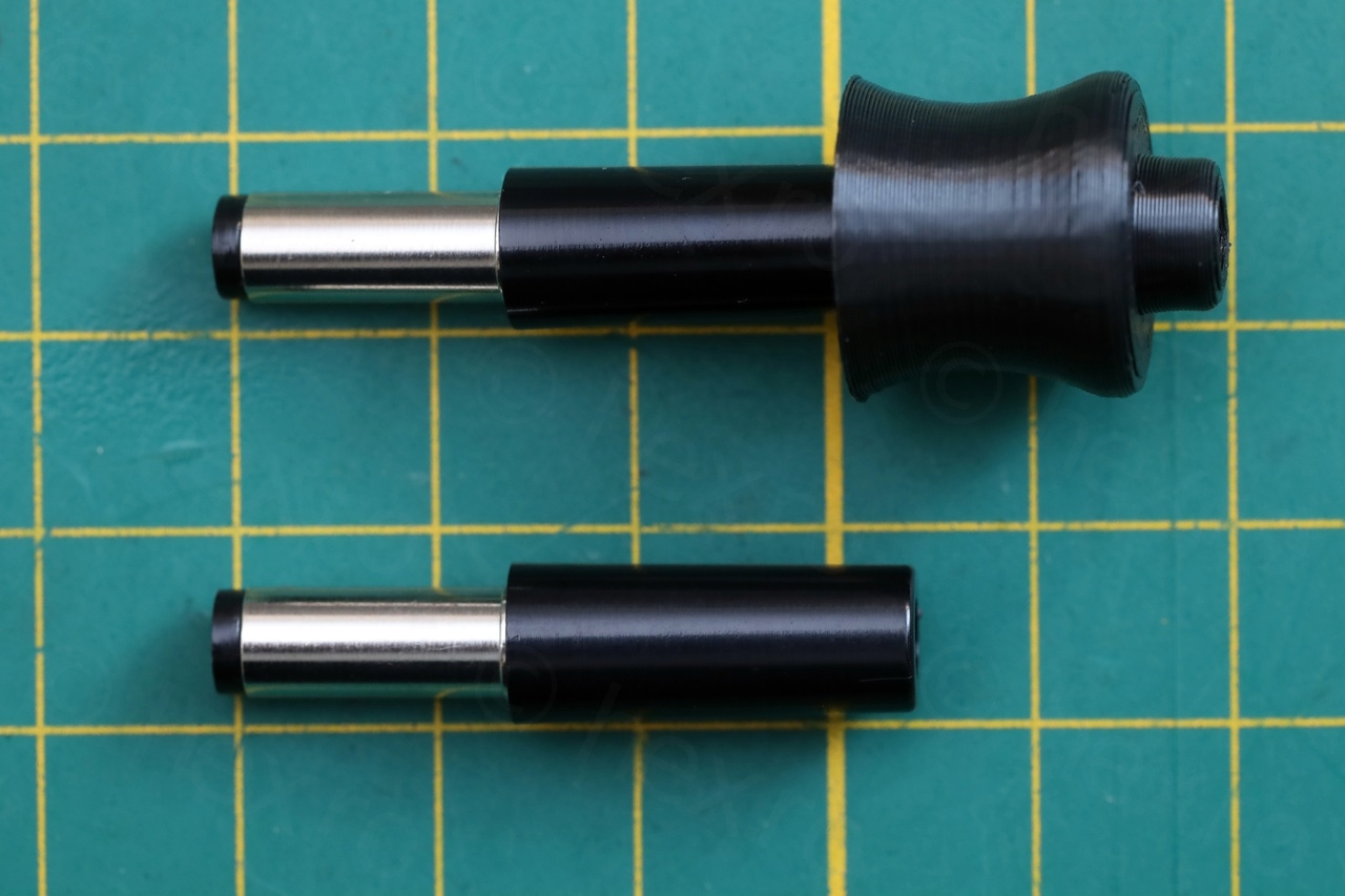
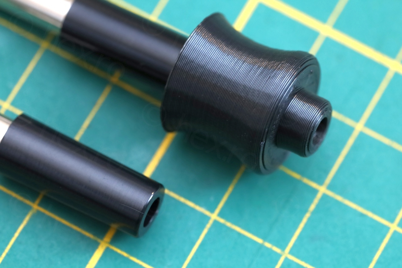
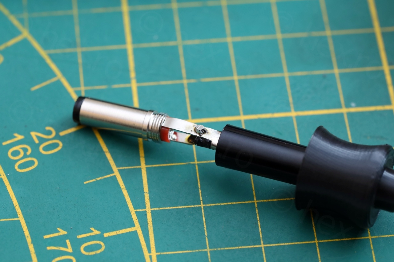
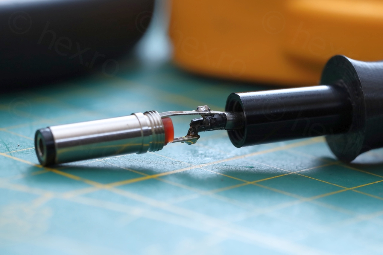
Seems fine, it is very easy to grab it now – problem solved.
Battery replacement ?
I would like to be able to power the scopemeter without having it plugged to mains, but this won’t happen very often. For my current debugging needs I use a simple DS203 which is very handy … I have to fiddle it to change the parameters, at least it gives me time to think about the circuit !
Buying an aftermarket battery for the Fluke 97 doesn’t seem so enticing. I would have to take battery out before putting it into storage, then mount it again rarely when I need it. But then wait for it to charge, etc. For my use case it would be overkill.
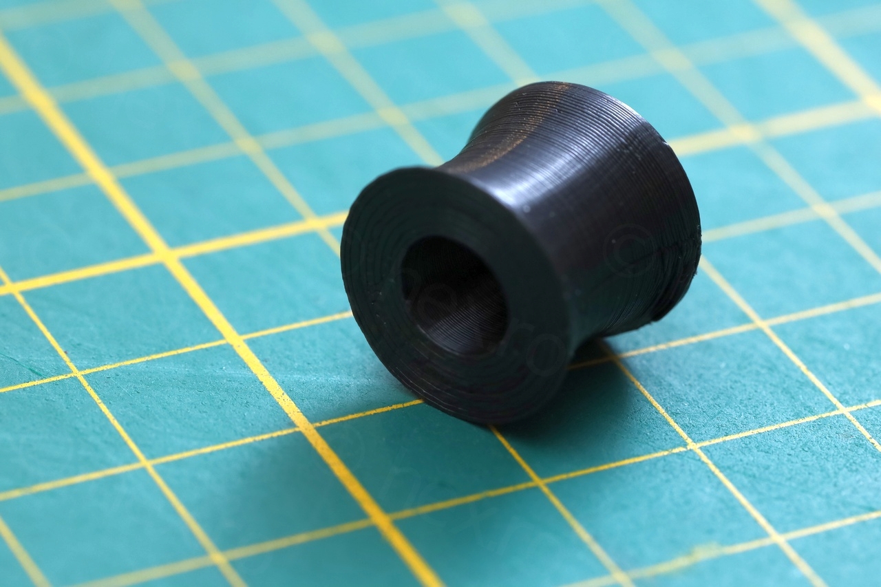
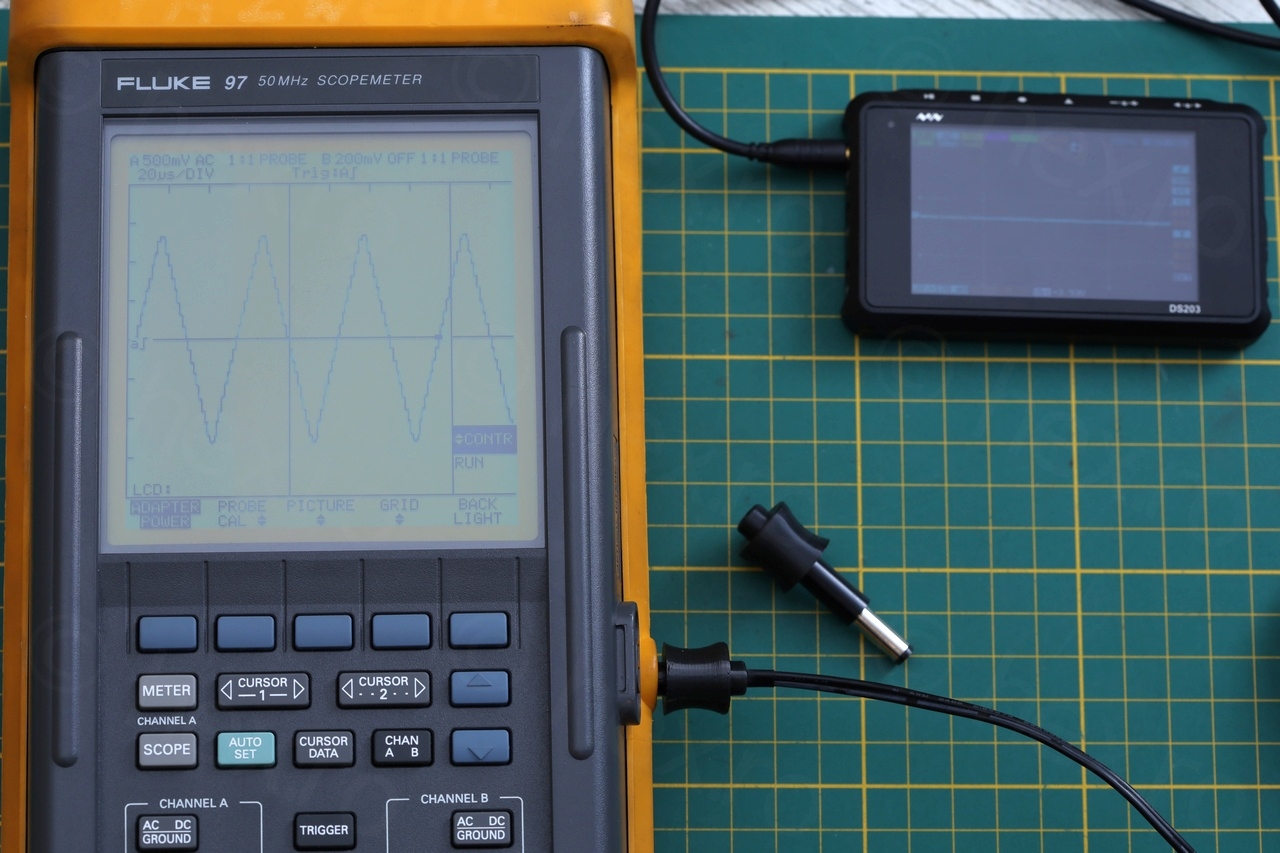
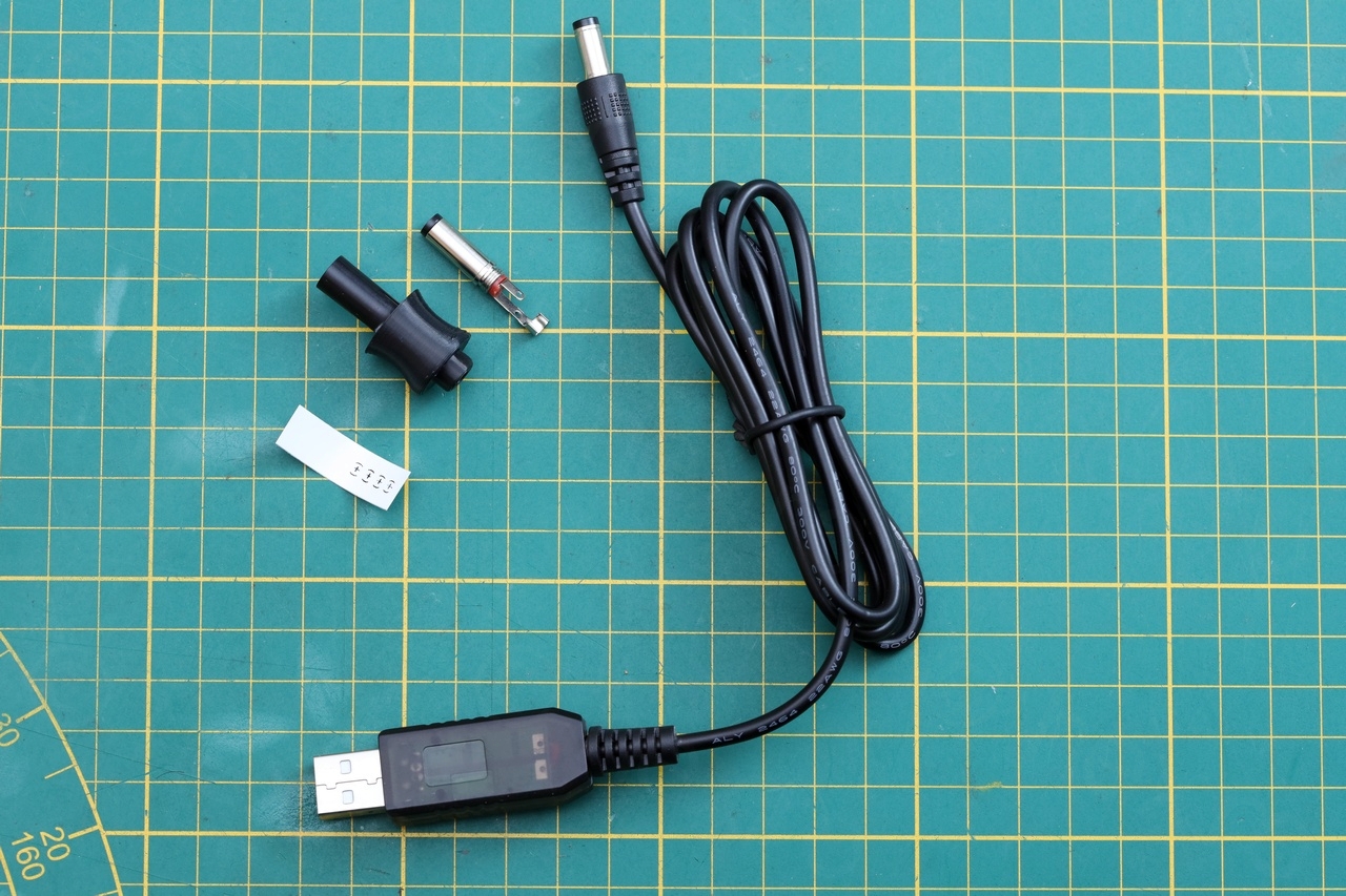
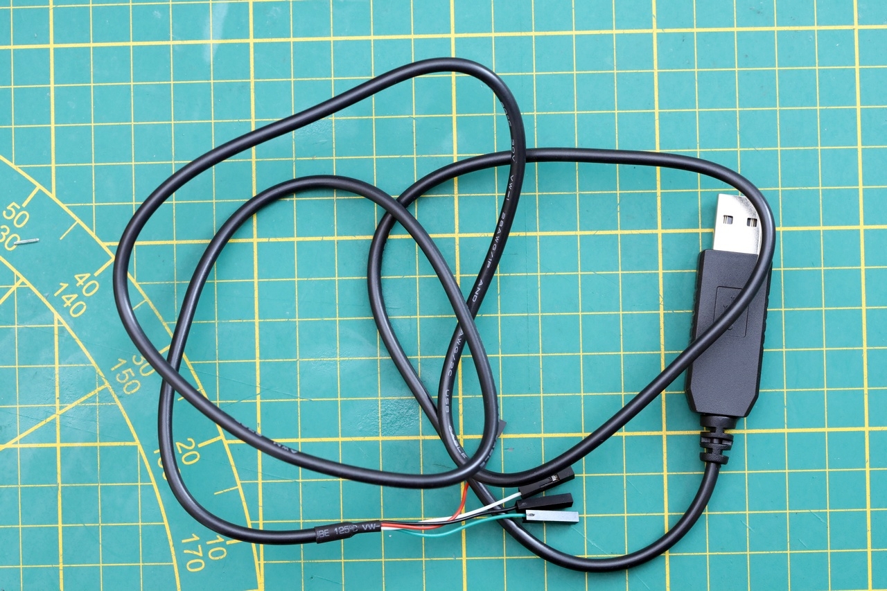
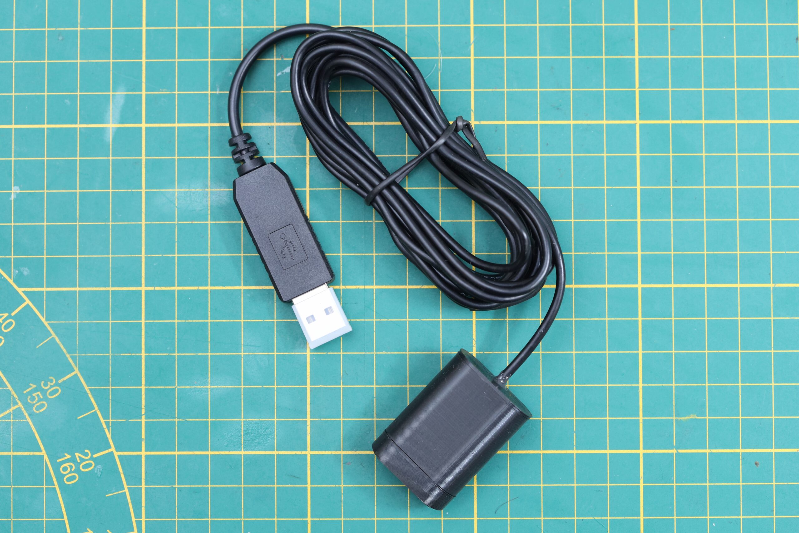
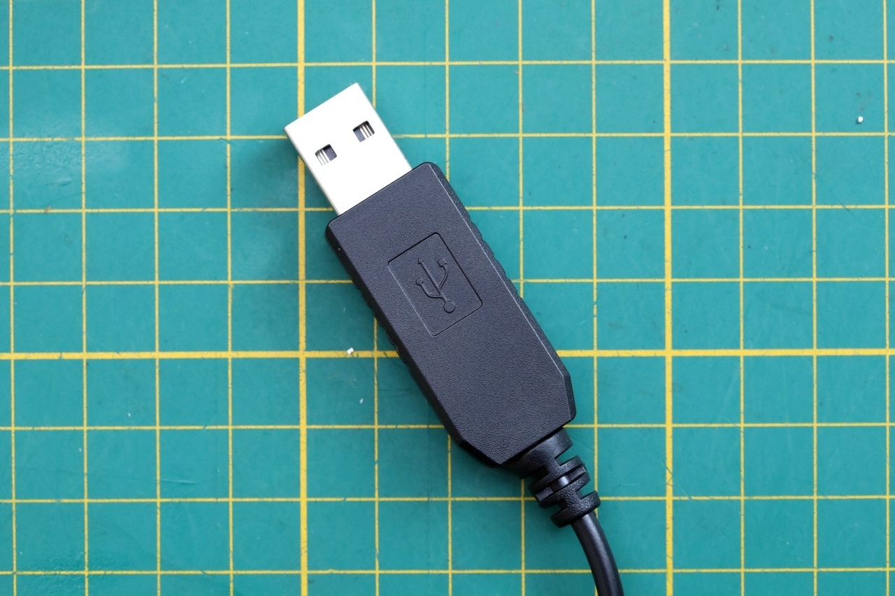
However, I remember seeing some power USB cables. You plug the cable into a standard 5V USB and you get 12V @ 1A at the other end. This is what I went with. I 3D printed another extender, ordered a very cheap USB DC-DC 5v to 12v cable, and now I can use a 10000mAh battery to power the scope when I need it, using the normal DC plug of the scope.
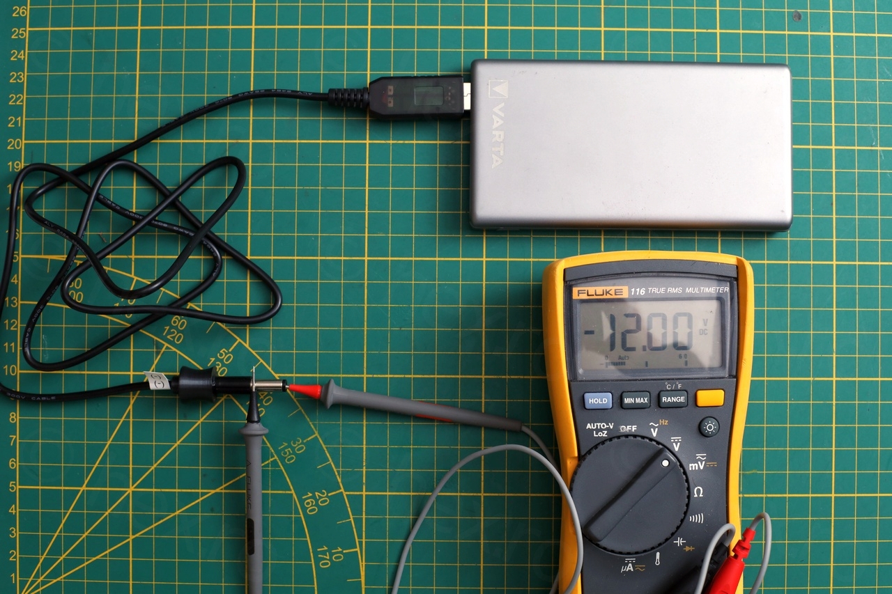
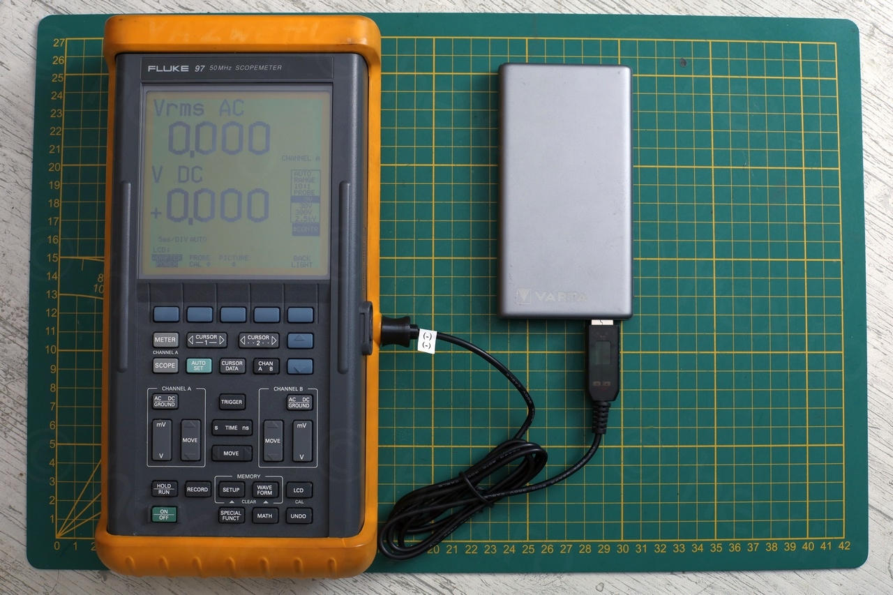
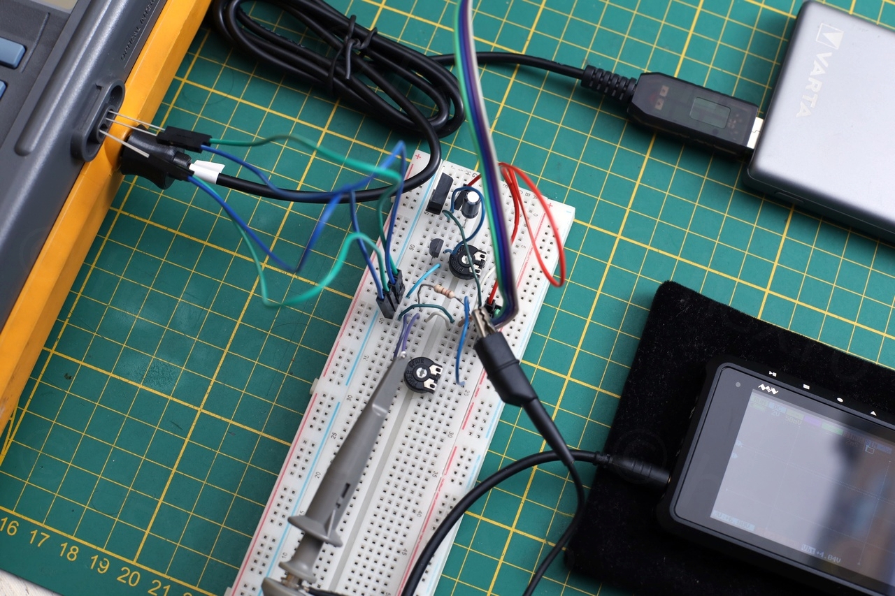
I made some measurements to see how much power is drawn using the DC-DC converter cable:
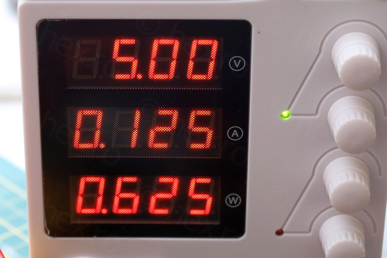
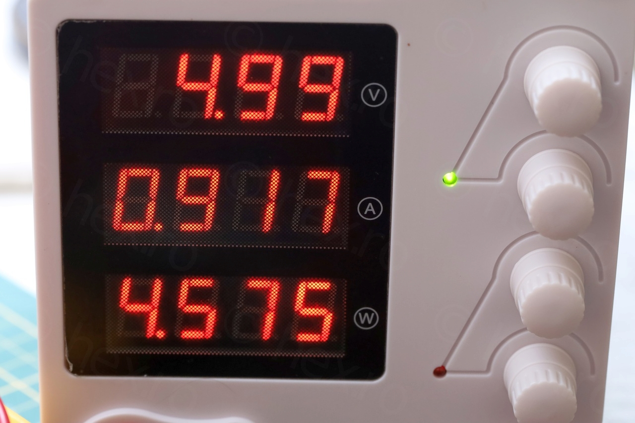
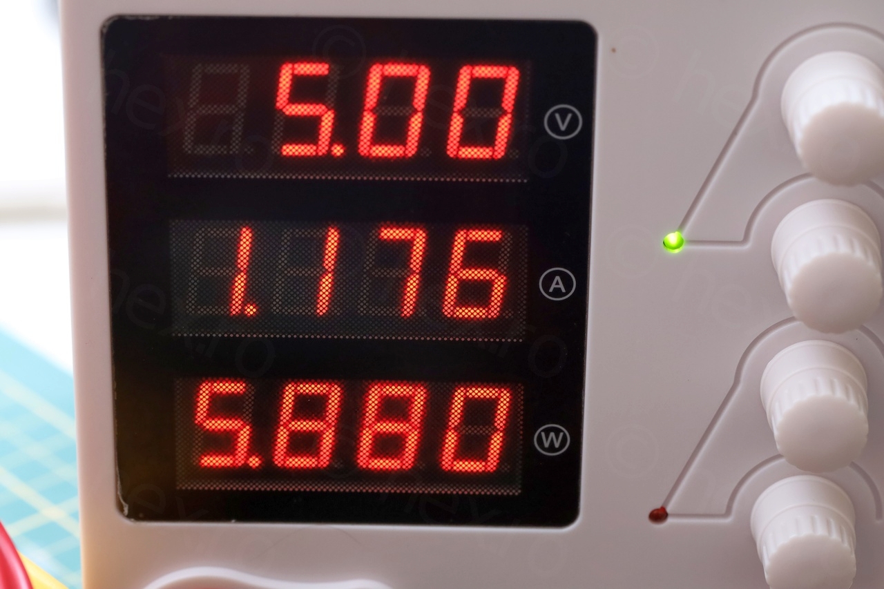
Just having the DC-DC converter cable plugged into the scopemeter, 0.12A is drawn. Turning on the scopemeter makes consumption jump to 0.92A. Having the backlight on, the consumption goes to 1.18A. Thus, assuming the battery does provide 10000mAh, this means more than 10000 / 1180 ~= 8h or so of runtime with backlight on.
The drawback is that oscilloscope is not fully isolated anymore. There is an exposed piece of metal (USB connector at the battery). However, if I really need to do some dangerous measurements involving line voltages, or in a messy environment where something could touch that exposed metal, I could always decide to use standard 1.5V batteries that the scopemeter takes.
Fluke 97 DIY Infrared Cable
By now I was set on re-accessorizing my lonely Fluke and next step was DIY an infrared cable for the Fluke 97. I considered ready made, but the cheapest I could find on EBay costed 95 euros + 9 euros shipping. Was not willing to pay that much for a “wire with two LEDs”, especially since I won’t be using it so often. Felt like putting 100 euros in Fluke’s storage box and leave them there.
But how cool will it be to see a screen capture on my PC taken from a 30 year old scope ?
So I have started reading the few articles online that are mentioning the cables. There was some trial and error needed – but was willing to try to make my own cable.
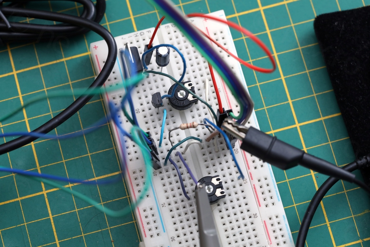
I went through some iterations (more below) but the schematic I came up with is this one:
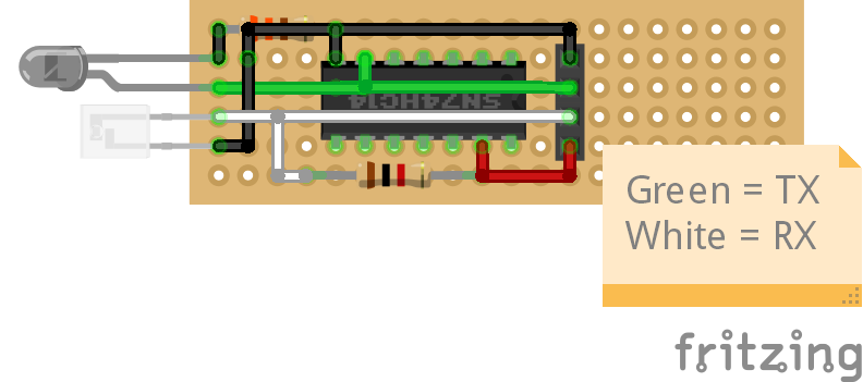
The IR parts are an IR Phototransistor (sensitive to 940nm) and an IR Emitter (950nm), both 3mm diameter. For the IR Emitter LED, I have calculated it to 330Ω, but for the resistor in the transistor’s collector – I used a potentiometer to look at the waveforms and settled for 1kΩ value.

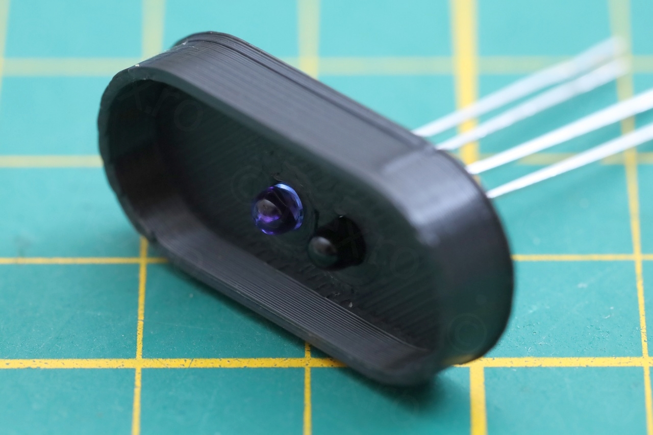

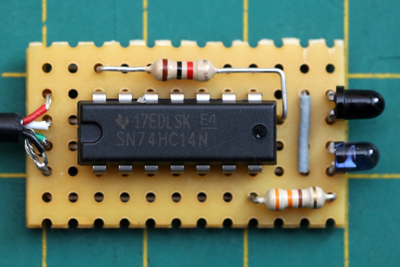
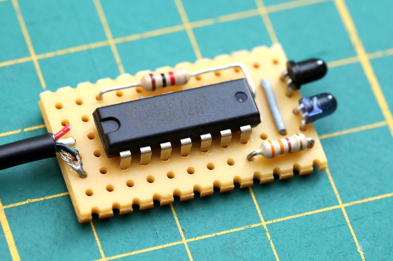

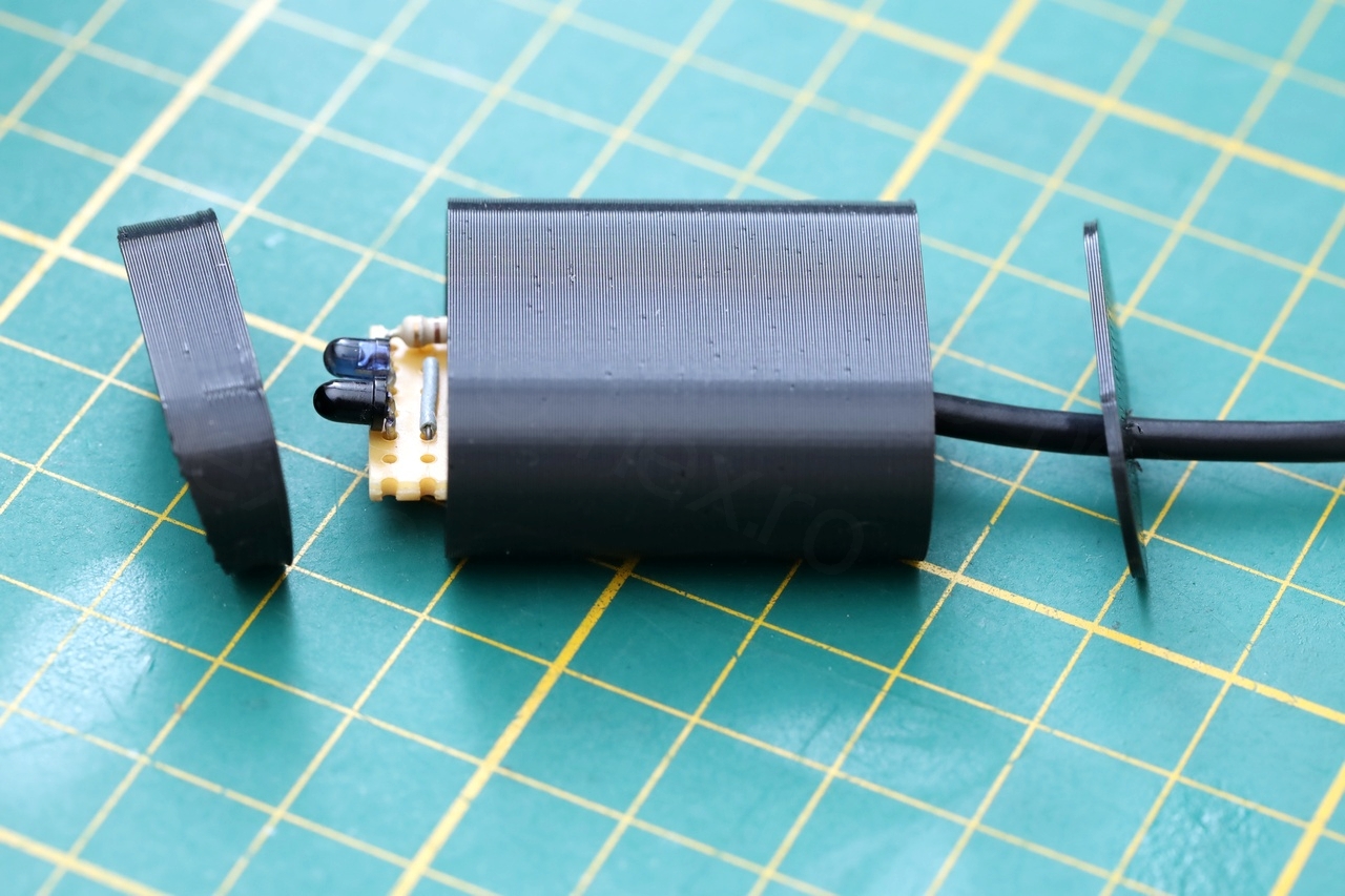


That above is the final result. But … before this, mistakes were made.
First mistake was to think that a IR photodiode would work – as I did ordered some 3mm ones. However, what was needed was a IR phototransistor, as the diodes need another amplification stage which would not fit in the little circuit board that I was envisioning. Then …
Shall I say that last time I had to consider serial communication was maybe 20 years ago ? I forgot that TX signal (computer TX, which has to turn on the IR Emitter LED) is idling at 5V and becomes active low by dropping low to 0V. So I had my IR Emitter LED always ON since I was using the TX as “VCC” for the IR Emitter LED. Then I realized I can’t reverse the direction and use TX as “GND” for the IR Emitter LED, since my cable had 5V VCC rather than the 3.3V TX levels. In this scenario, the LED will also be ON, because there will be 1.7V across it when TX idles high.
First successful test was using an LM33V to drop the 5V to 3.3V and then a PNP transistor to invert the TX signal, following a schematic similar to https://github.com/openv/openv/wiki/Bauanleitung-RaspberryPi:
For the RX signal, I used the IR phototransistor in its Common Emitter configuration, picking RX voltage from its collector (since the transistor is naturally inverting). Still, this many parts were too many to fit on the small circuit board, so … I kept looking for other solutions.
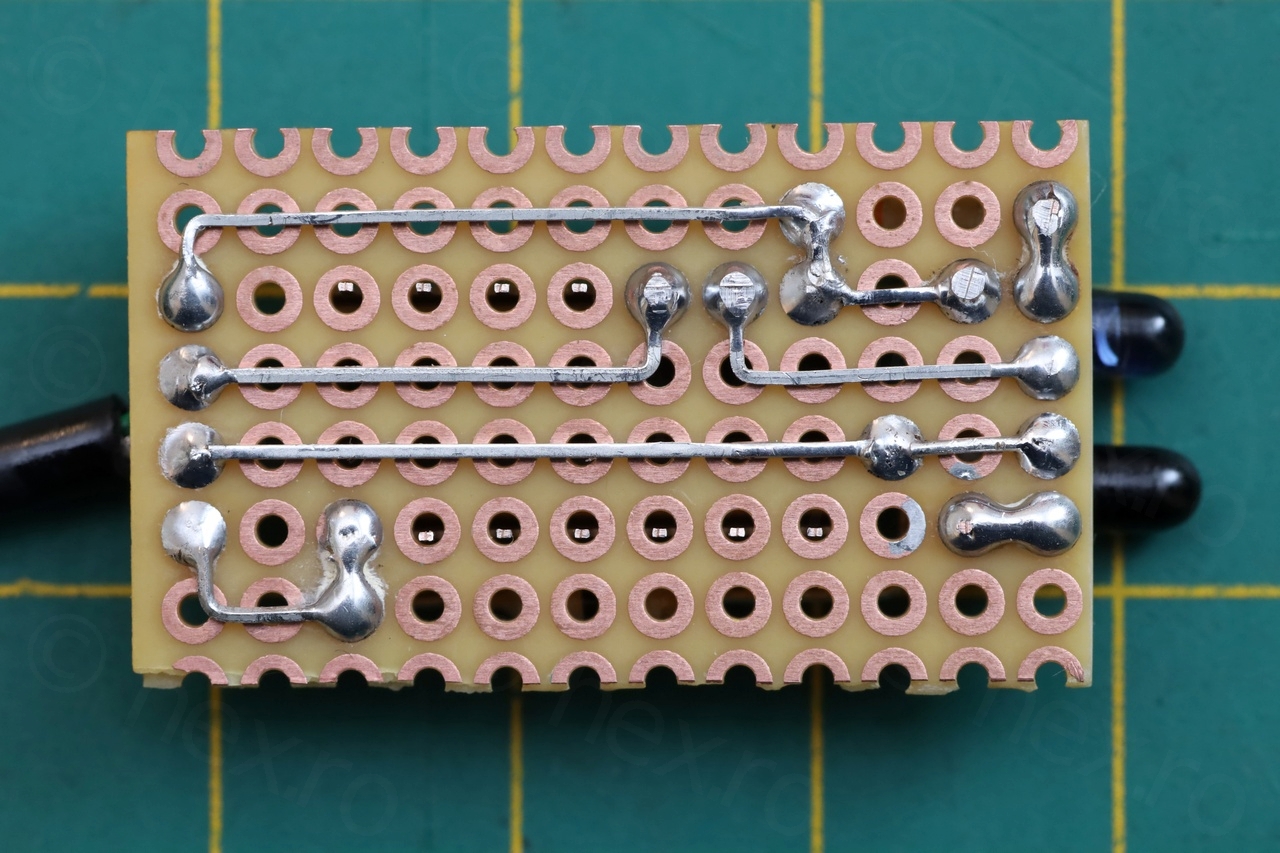
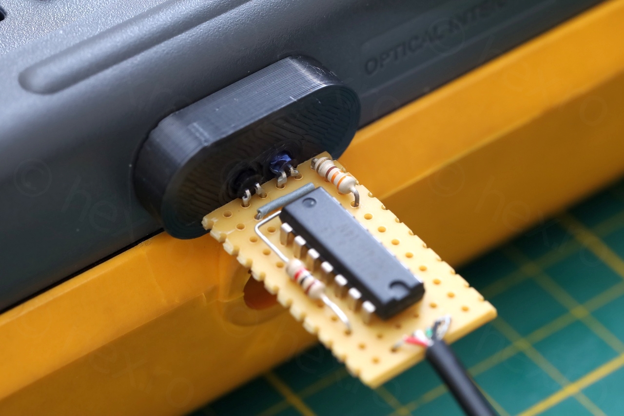
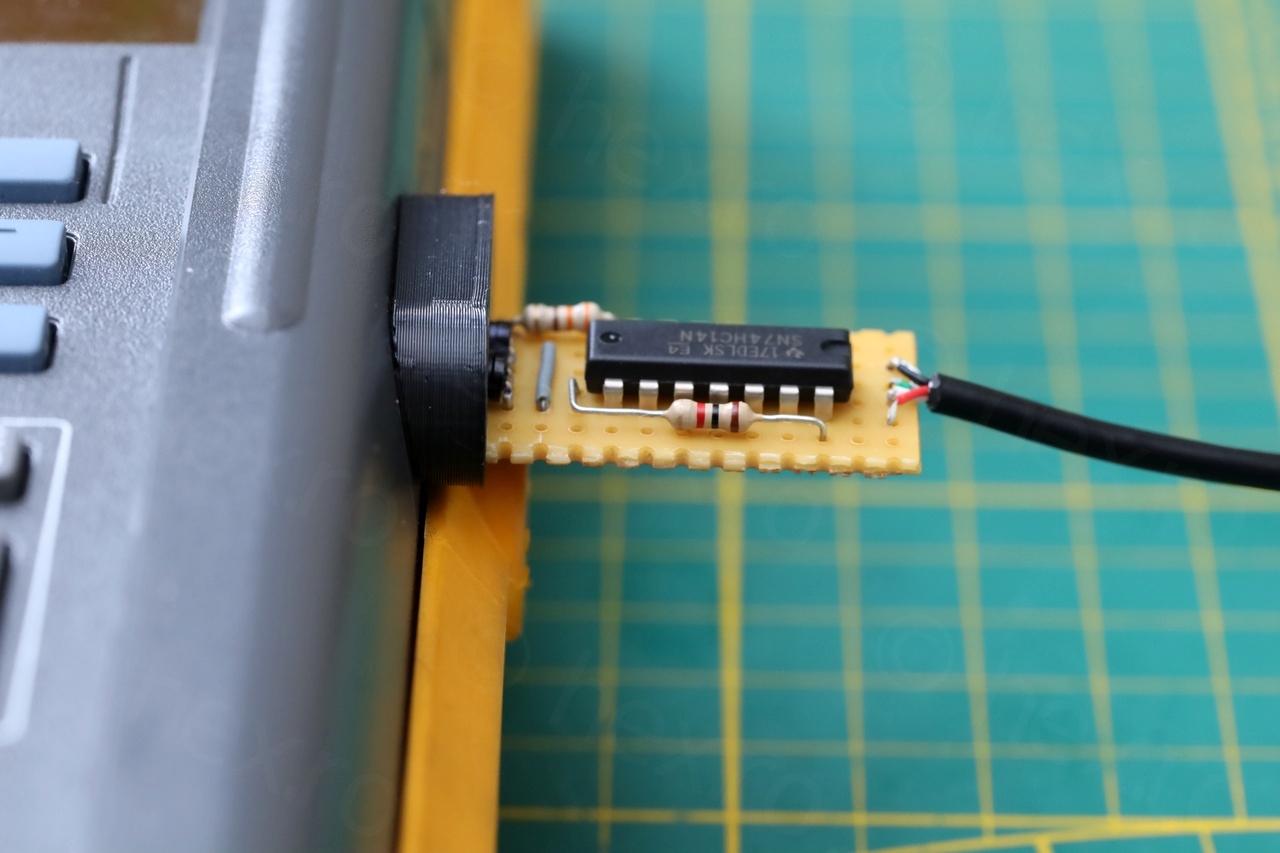
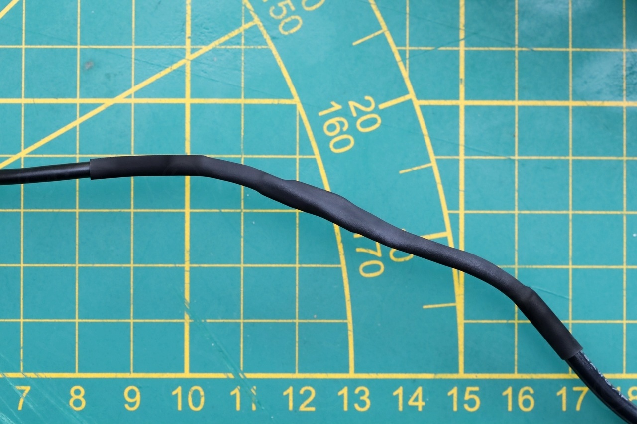
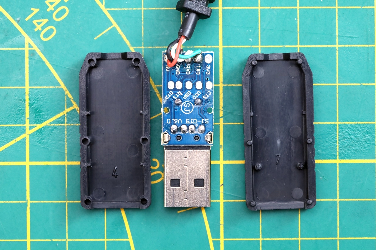
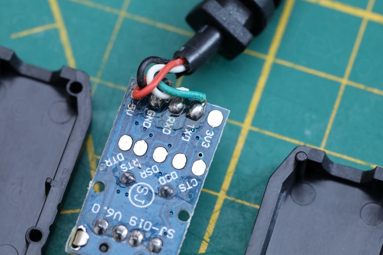
I have finally set on a Hex Inverter with Schmitt-Trigger inputs, the SN74HC14N – which is tolerant for 3.3V / 5V. It does work. I couldn’t find an 8 pin DIP variant, but at least I didn’t have to have an LDO with capacitors and a transistor. Wiring it was a breeze. I have also designed a small 3D printed connector that houses the little circuit.
Once I had the board ready, I discovered that in fact, my RS232 cable was capable of 3.3V – if only I would have taken it apart and checked it before 🙁 – by default it was wired to have VCC to 5V, but I could have switched the wire to 3.3V. Pfffff.
In the quest for inverting the TX voltage logic, I considered other solutions. The FT232 chip which is capable of inverted logic for the TX/RX signals, thus saving then need for transistors / inverters. I didn’t find any cable providing the the VCC of 3.3V though. The other available chips, CH340 or PL2303.., they don’t seem to support inverted logic.
I also played with an Arduino as a Serial Proxy – since “Software Serial” library allows for inverted logic of the pins. While this works from hardware point of view, ScopeGrab32 (freeware screen capture application) doesn’t like the additional time it takes (at 1200 bauds) to get a response from Fluke 97. It has a timer of 1 second and Arduino as Serial Proxy was taking just a little more to get results.
ScopeGrab32 modifications
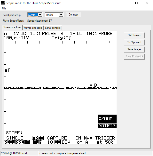
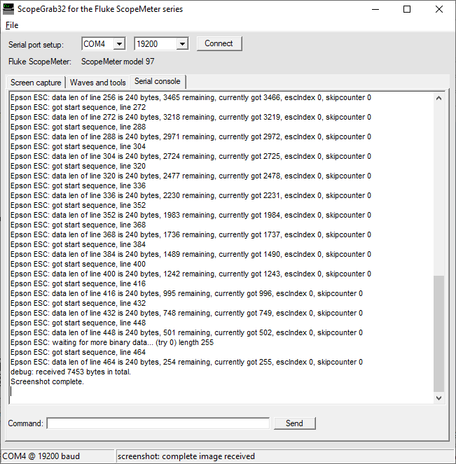
With a working IR cable I started playing more with ScopeGrab32. It was always failing after downloading the screenshot that “screenshot: incomplete image received”. Although the image seemed fully downloaded.
Was able to migrate the CVS repository of ScopeGrab32 and found a old DevCPP (with mingw 3.3.1) IDE and the corresponding wxWindows devpak from the Web Archive. And started digging. I found and fixed a bug where it would miss that the image finished downloading, since it was not checking for the number of rows reaching the end. This caused 4 more seconds delay for some additional retries until it gave up with the annoying “screenshot: incomplete image received”, although full image was retrieved.
Below some screenshots with ScopeGrab32 now working:
I haven’t had time to put everything on github, but I will at one moment.
Scopegrab32 has a lot of complex code handling the fact that Fluke sends image data in chunks. On my system serial data always arrived fully after few seconds of waiting even if I disabled buffering in the Driver’s Control Panel. Maybe other Flukes send data in smaller chunks ?
Final thoughts
Having fixed the scope and accessorizing it, I am half happy but also half sad. Fluke 97 is large and heavy – perfectly understandable for a 30 year old portable oscilloscope. But if I compare it to modern lightweight ones that make it a breeze to save images and have better refresh rates, it does feel outdated. I am happy I didn’t pay that much to discover that for it may not work out so well for me in the long term. I will give it some time though.
What else to say …
The backlight seems bright enough. Having never seen a brand new Fluke 97 lit up – I can’t really say if it is faded or not. I did order a 10cmx10cm aftermarket EL panel (with tabs in the middle instead of the side) – the new one is brighter. But I decided not to replace the stock one, it is still readable so at least better conserve the meter as close as possible to stock.
On top of that, there is an audible high pitch sound coming from the device when the backlight is on. It was hard to record it, got the microphone very close and still used Audacity to amplify the recording with 30dB:
I saw many posts saying that the holster plastic breaks down in time. I applied a thin layer of silicone grease all around it, using a paint brush to get into the square cells, after reading that plastic breakdown is due to Oxygen exposure. I have no clue if this is the reason of the degradation though.
The scope was also paired with some 60MHz oscilloscope probes, themselves isolated too (no exposed metal part where they connect to the scopemeter).
Looking forward for the next project where I’ll try to use this Fluke 97 to debug the circuity just to see 🙂 how it feels.
Thane Guiver
hi.
sounds like you nailed the problems a lot if us have seen with these fantastic meters.
I was wondering if you had come across a situation were channel A although is receiving a 5v square wave, the scope starts to auto range until its off the scale. I have two scopemeters doing this now. still haven’t gotten to the bottom of it yet.
this happens if you use it as a metre or a scope.
interestingly channel B works just fine.
would really appreciate any thoughts or suggestions you have? thanks.
Best regards
Thane
viulian
Hello,
I didn’t go into the schematics – to be able to have suggestions on the problem you describe.
Will have to test the scenario.
It may take a while, but maybe not so much. I revived another scope meter with keyboard issues – due to leakage from the same 4 capacitors. But I didn’t finish putting the article together (photos) thus I will give it a try.
Best regards,