


This sewing machine was bought for a very good price at a flea market, but it did not work. Only the light come on, without any other sign of life. The machine eventually it made its way to me. Even if I don’t have experience fixing sewing machines, at least I can try to understand why the electrical part is not working.
Table of Contents
- General Overview
- It is broken
- Analysis of the Power Supply
- Main board issues
- Cleanup and Wrapping it up
- Remarks
- Results
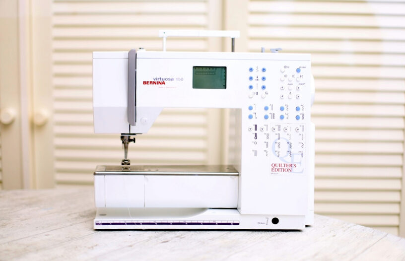
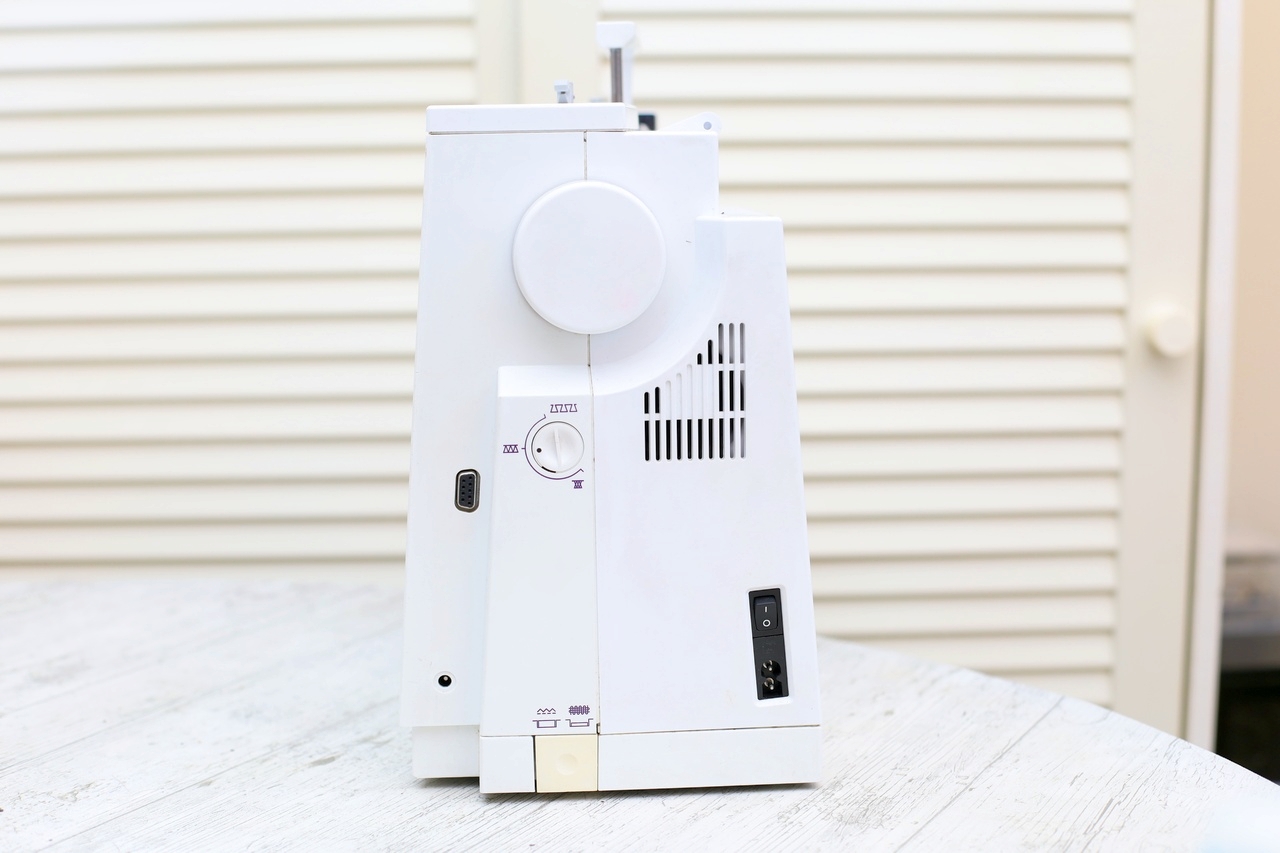
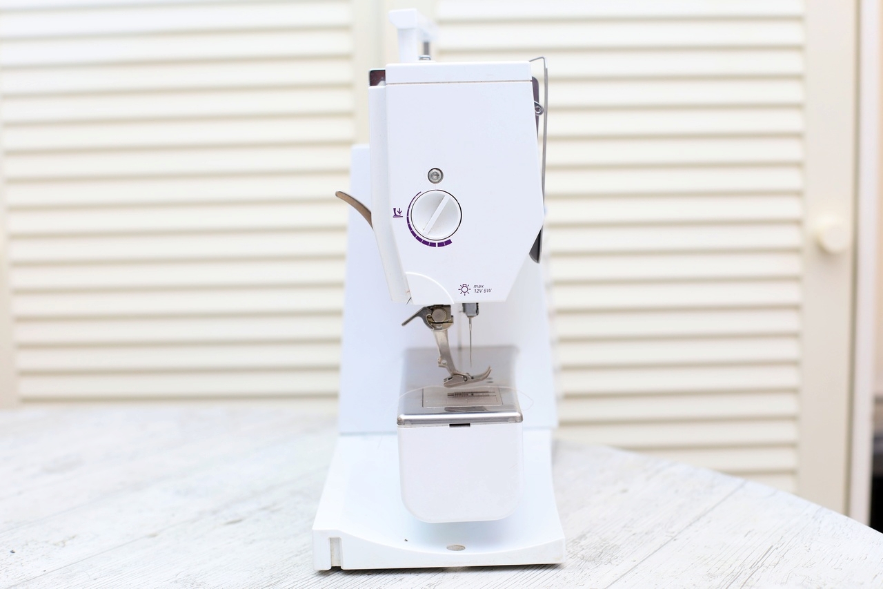
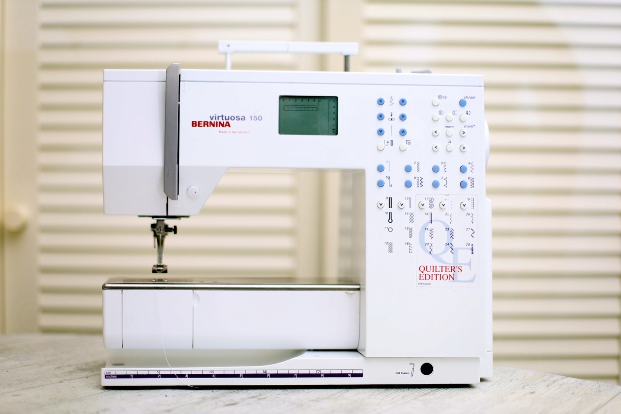
General Overview
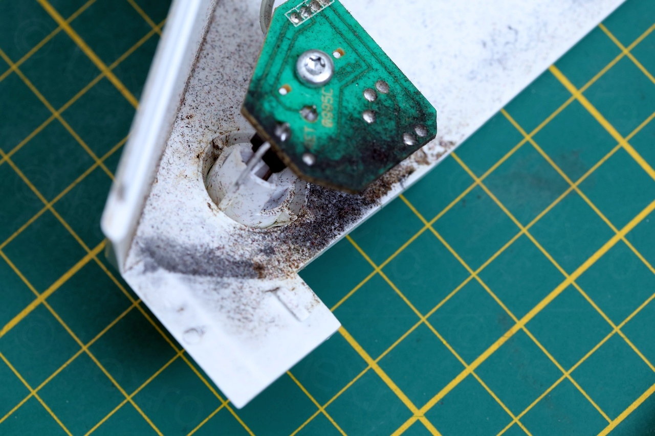
The machine was in very sad condition, dirty, cracked plastic and generally, looked abandoned:


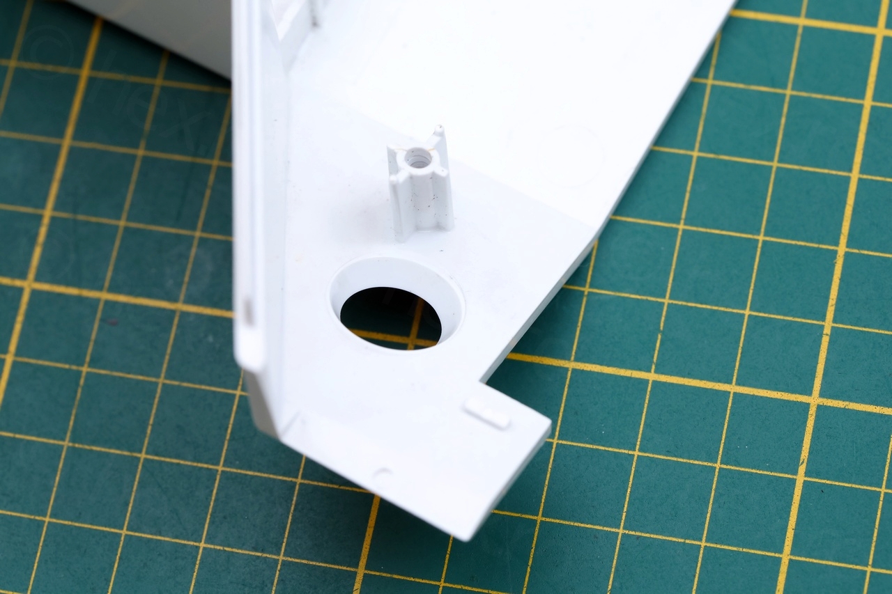
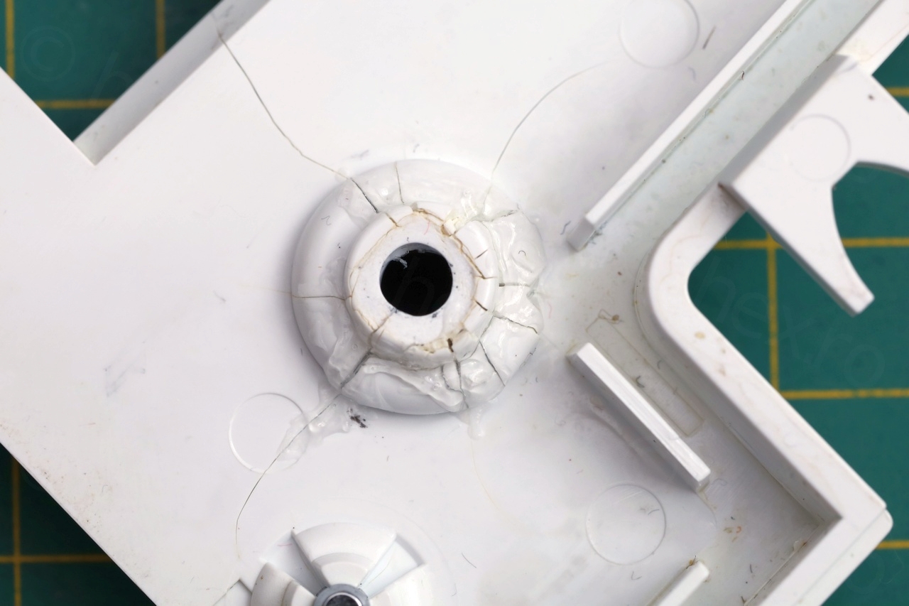
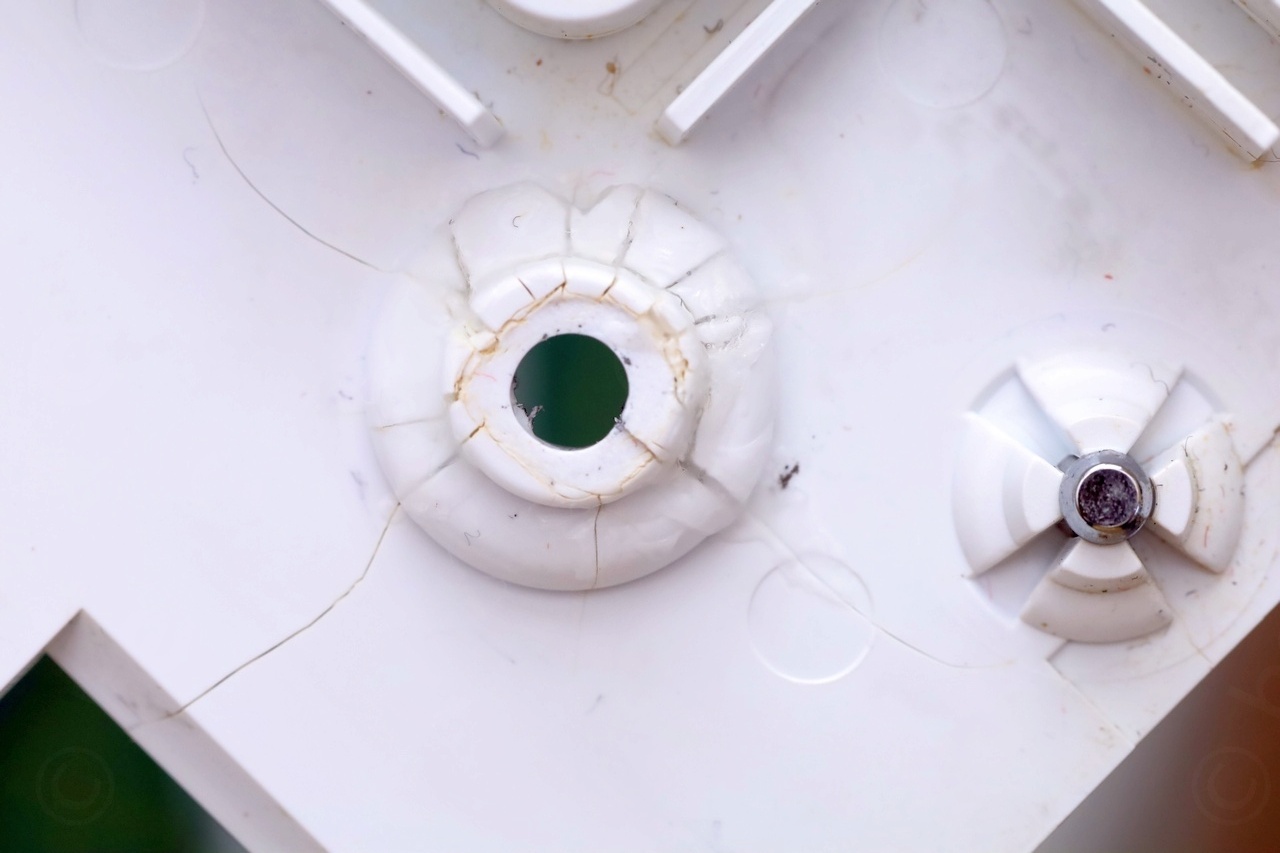
The plastic around the counterbored holes was cracked – like too much torque was applied when tightening the screws down:
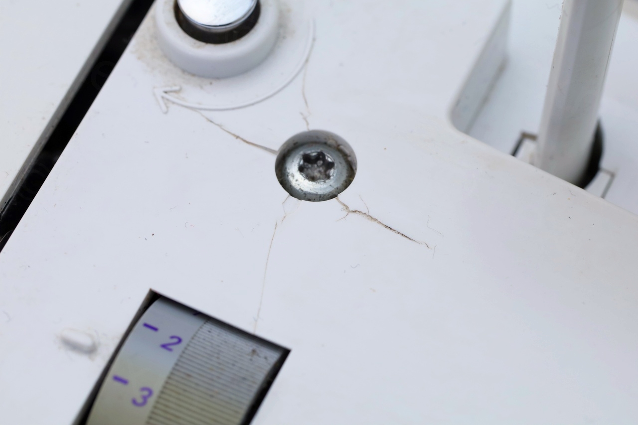

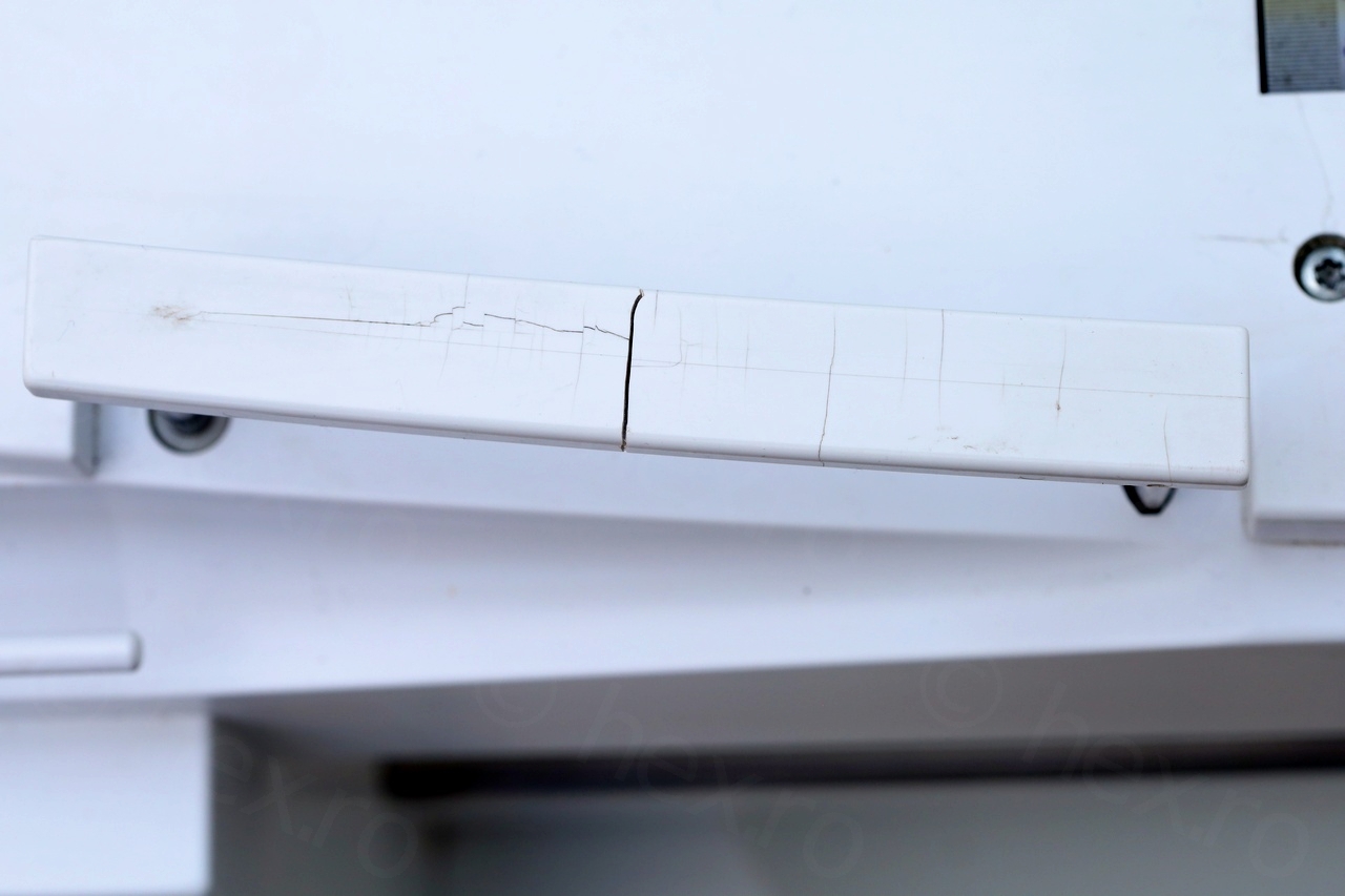


Initially I thought that somebody was careless when putting the machine back together, but then I noticed that the plastic was cracked in flat areas too, without obvious dents – I cannot not explain how this can happen. Did somebody tried to just pry the plastics off ? Or was the machine just being mishandled / dropped ? Or plastic just too brittle to handle the vibrations ? There were no obvious signs of it being dropped. Weird.
It is broken
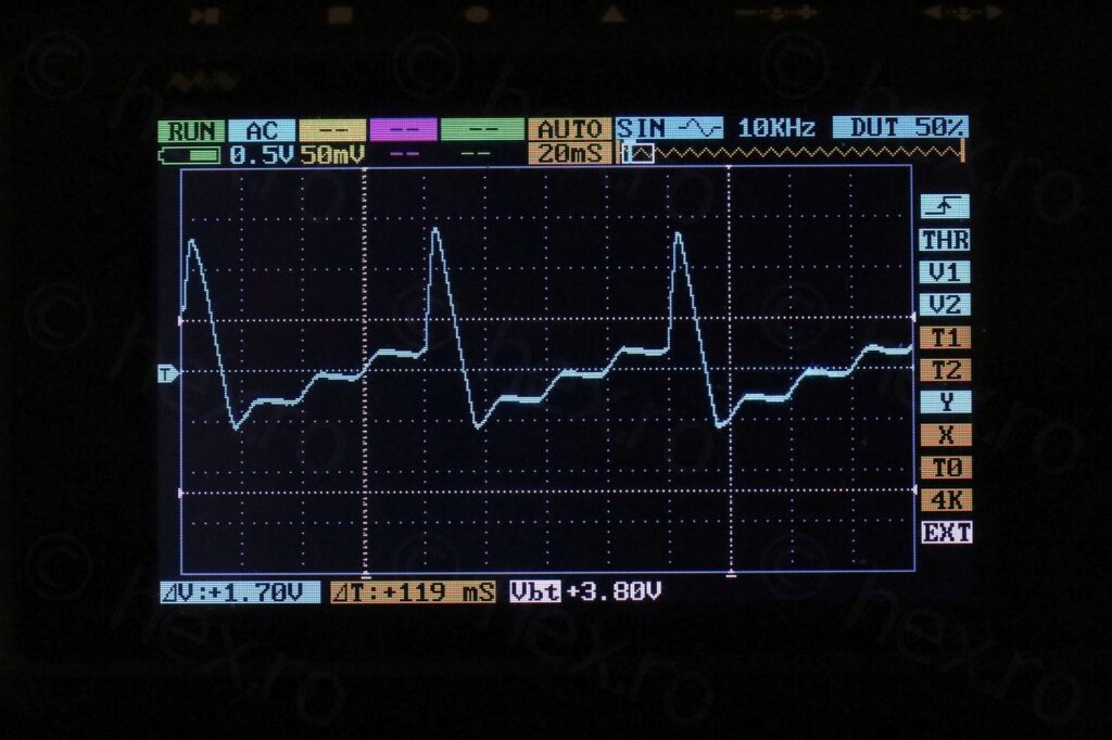
When I powered it, only the light turned on on. No startup noise, no LCD backlight, dead except the sewing light. Even this had issues, exactly at turn on it was very bright, then dim, then bright again as power is cut off. Below few cycles of on / off:
Analysis of the Power Supply
A word of caution, handling power supplies involves dangerous mains voltage, and if you decide to proceed – you do it at your own risk. I took some precautions, but not all.
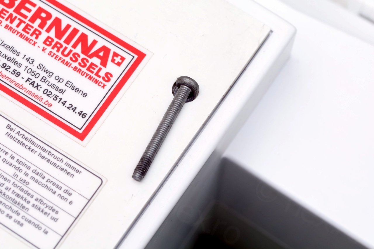
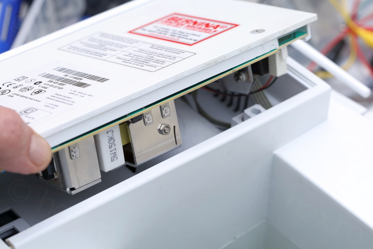
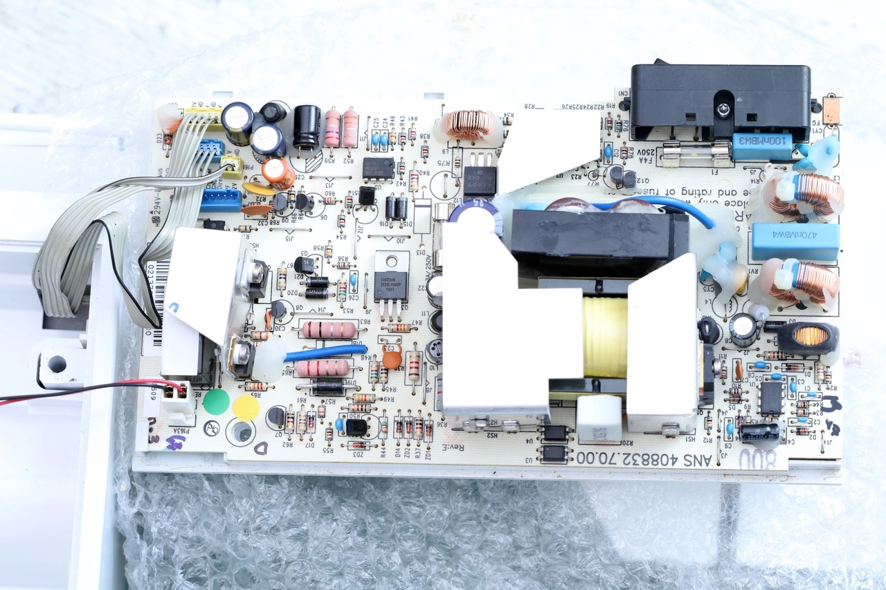
To take out the power supply board was easy, one big screw and then lifting up the back panel:

I also had a look online for schematics but I could not find any. Some websites are asking approx. 15 euros for a service manual, but if it does not contain the schematics / voltages, etc – then it would be a waste of money (from the electronics point of view).
Given it was the first SMPS that I was trying to diagnose, I kept a very detailed log book with the analysis, but to save your time, I will only post what I consider the more important points.
- the 3A slow blow fuse was damaged
- checked all semi-conductors for shorts, found none.
- checked all capacitors (in circuit) with an ESR meter, they all seemed fine.
- built the test circuit for UC3843 using a brand new UC3843 to check the test circuit. The UC3843 of the machine tested fine in the jig, so I re-installed it back onto the board.
- pulled the K2699 MOSFET – tested fine, reinstalled.
- pulled the other shield to see the components hidden by it, they seemed fine too.
- the boards needs a load to start regulating – connecting a 12V/5W light-bulb on the 12V output is enough to stabilize it. Without any load, the UC3843 VCC oscillates around 8.3V and its VREF never reaches 5V.
- The 5.2V is rock stable, but the 33V line has a 6% ripple. I correlated the ripple (80ms interval) with the ripple on the VCC of UC3843. Since no parts seem defect, I choose to consider this normal although it feels like the 33V line should also be rock stable. If I would have more experience, I could tell, but without… I am just confused. 33V goes to power the motors and their drivers, so maybe it is not that important to be perfectly stable.
- VREF of TL949L was 5V rock stable, but its VCC is the same 33V line and has the same ripple. I tracked the ripple back to the the 12V coming out of one of the secondary windings of the transformer (and it is proportionally lower). The VCC of the UC3843 also has a small ripple, different shape, but same 80ms interval. But I can’t tell what is causing it ..
3A Slow Blow fuse is burnt
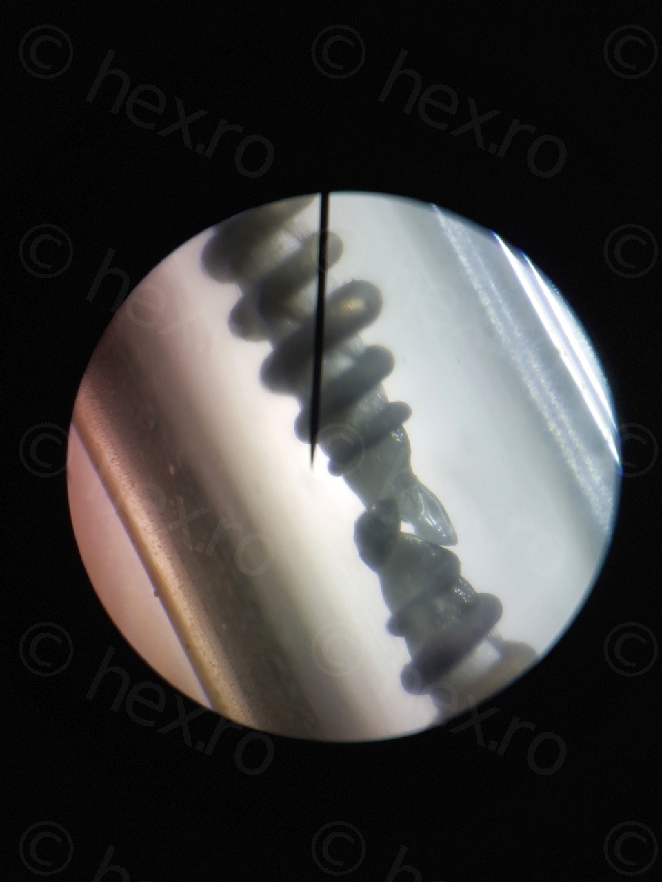
The first visible thing was that the 3A Slow Blow fuse was “eaten”:
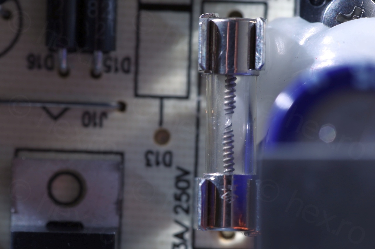
What could have caused it to burn out ?
UC3843 Open Loop Test Circuit
The next thing I focused on was the UC3843 IC that seems to be switching IC for the whole supply. Was it even starting ? And how is this whole thing supposed to work 🙂 ?
Most of the datasheets for the UCx84x IC contain an Open Loop Test Circuit. A breadboard build of the test circuit seemed doable, that way I could pull the existing IC and test it. Choosing RT/CT involves consulting the “Timing Resistor vs Oscillator Frequency” chart and I went with RT=18kΩ and CT=2.2nF for ~ 40kHz.
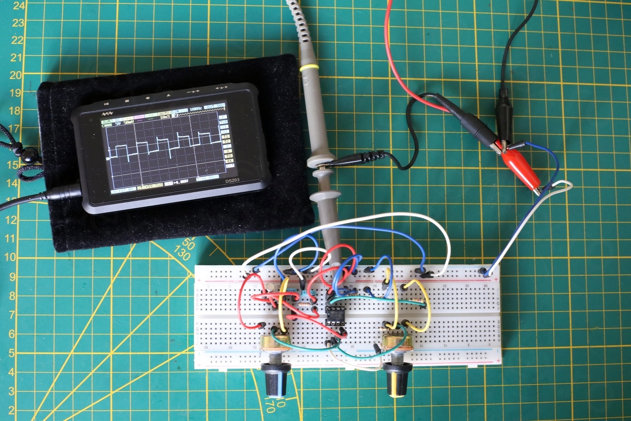
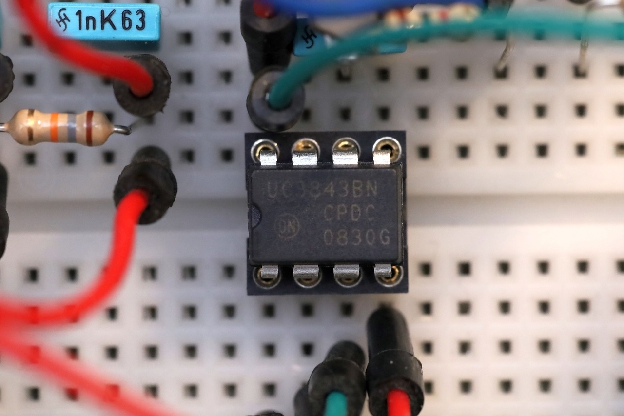
The only trouble was that the 1K / 5K potentiometers need to be fiddled with to get the circuit going. Initially I had them set at mid range was puzzled that there was no output. Once I started turning them, the circuit reacted. I bought a new IC to test the test circuit, and it behaved the same as the existing IC. I put the existing IC back, it was not the culprit.
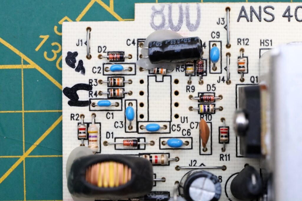
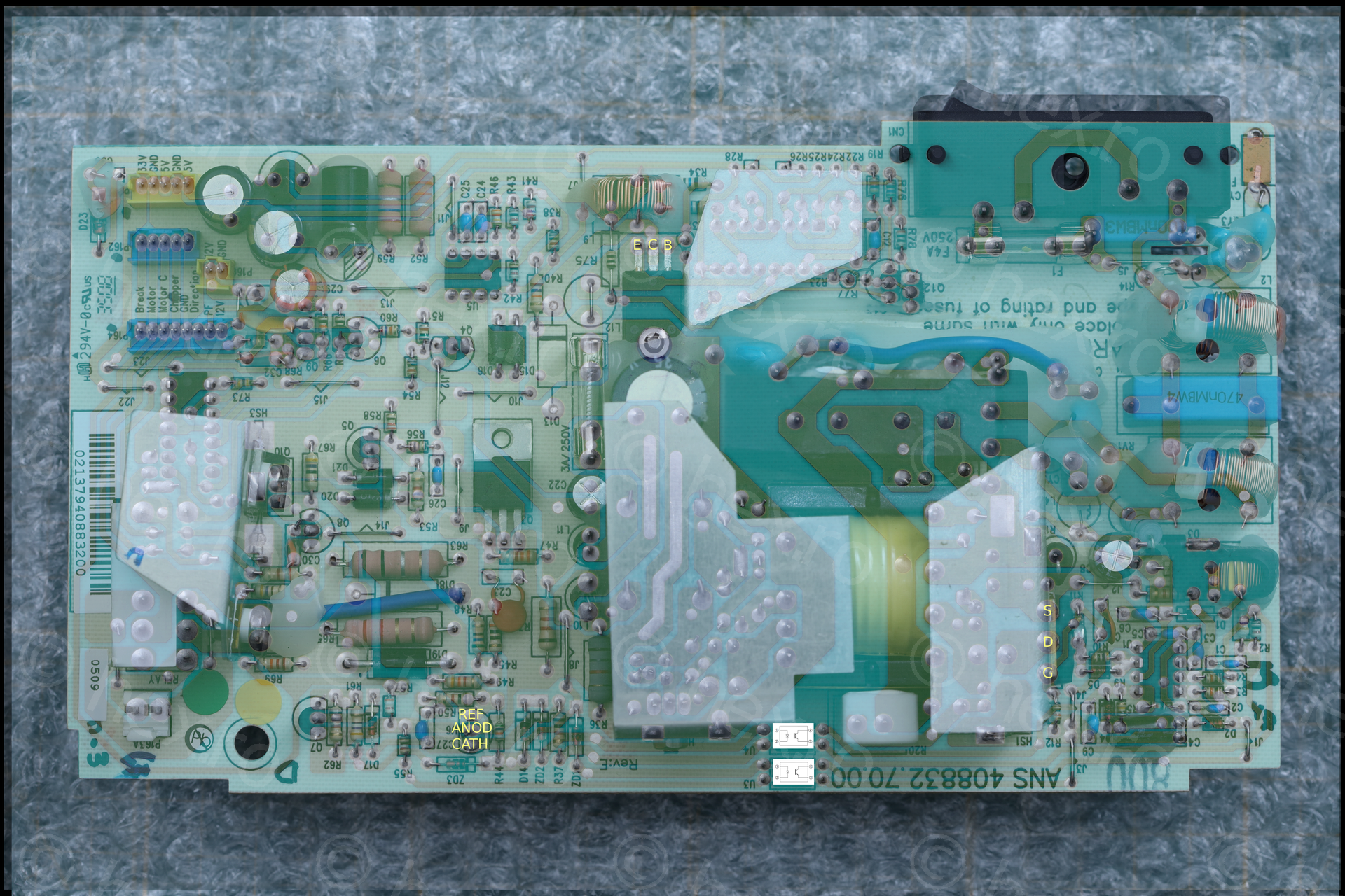
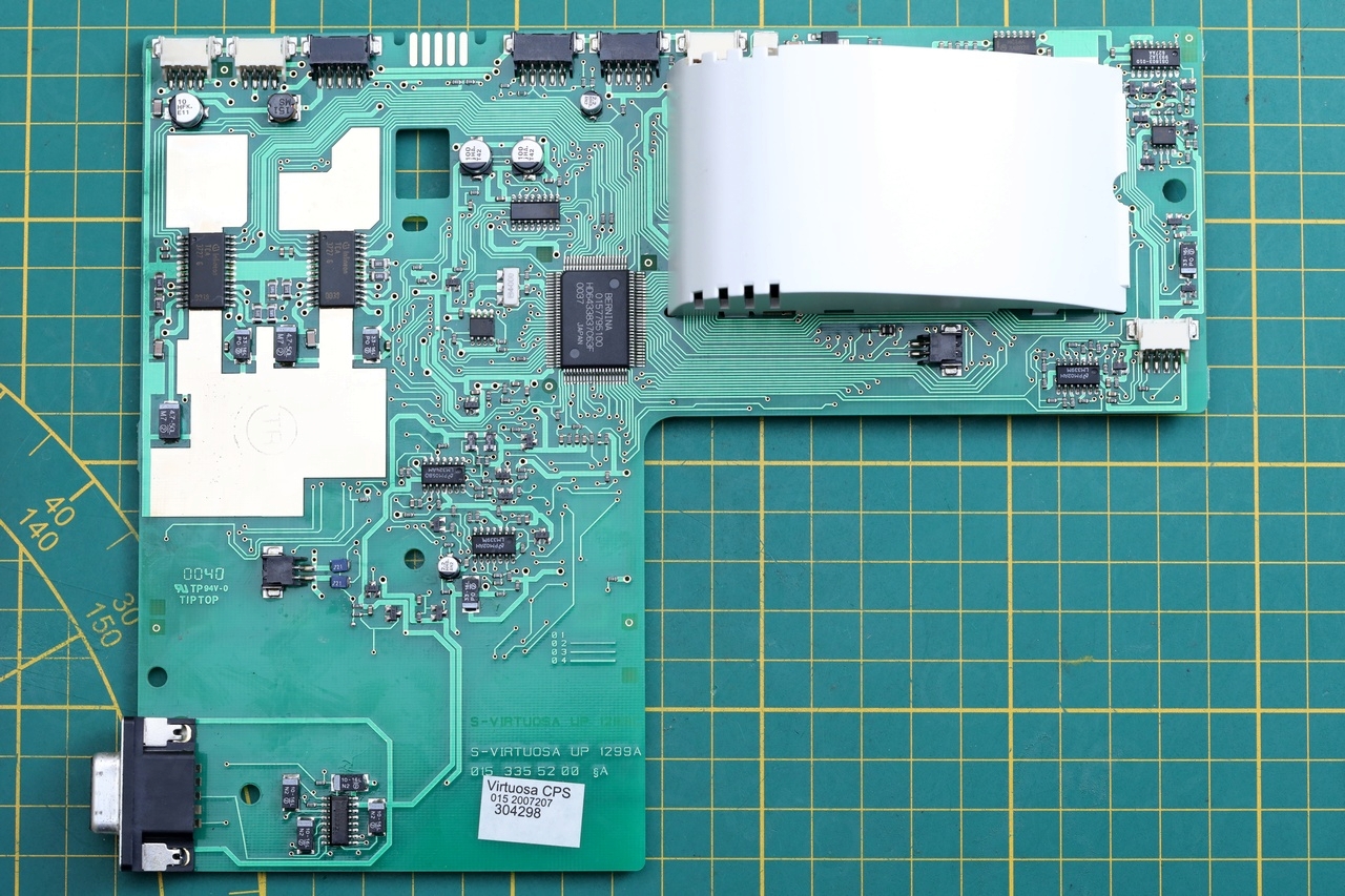
GIMP Component Layout
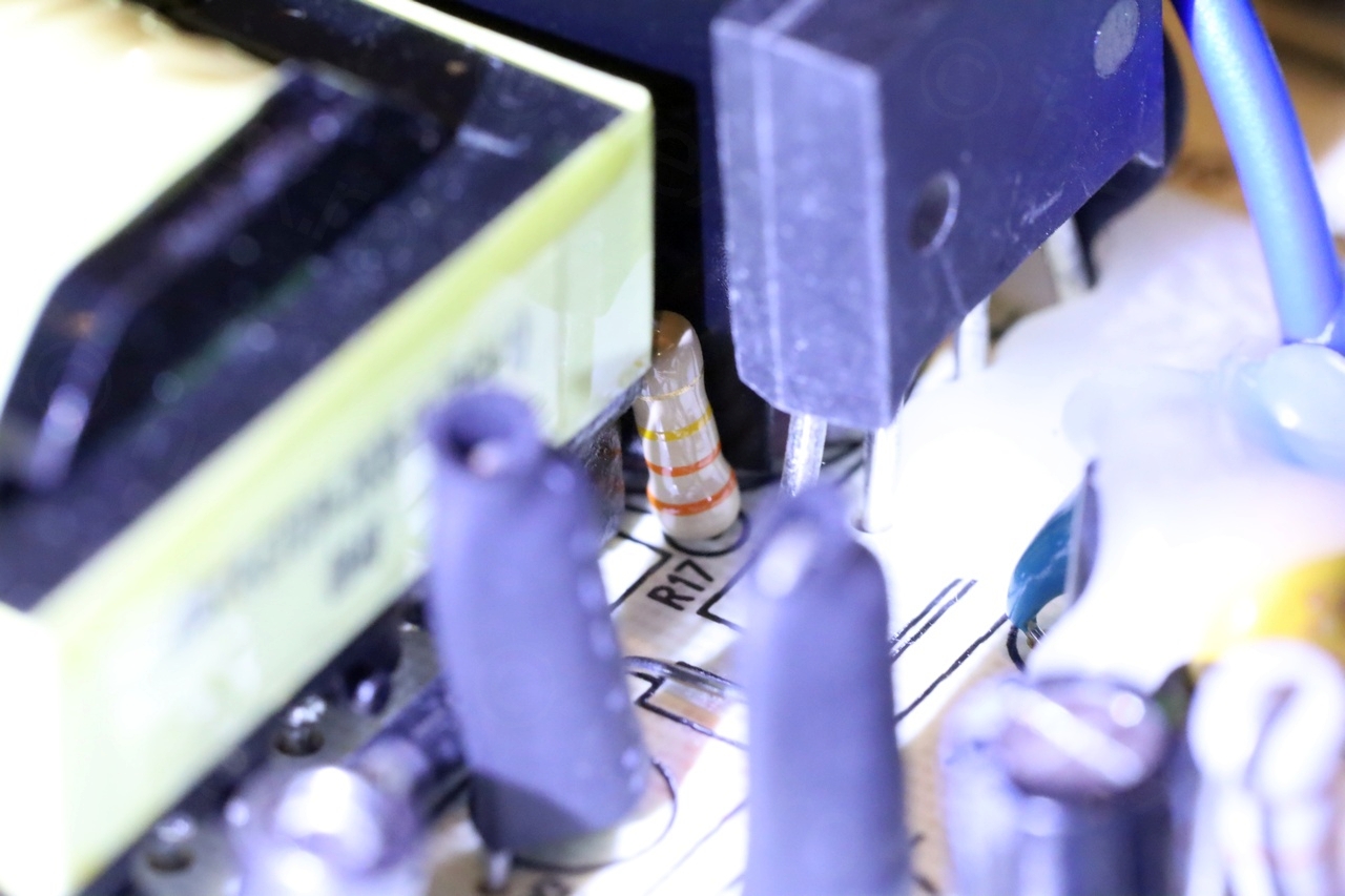
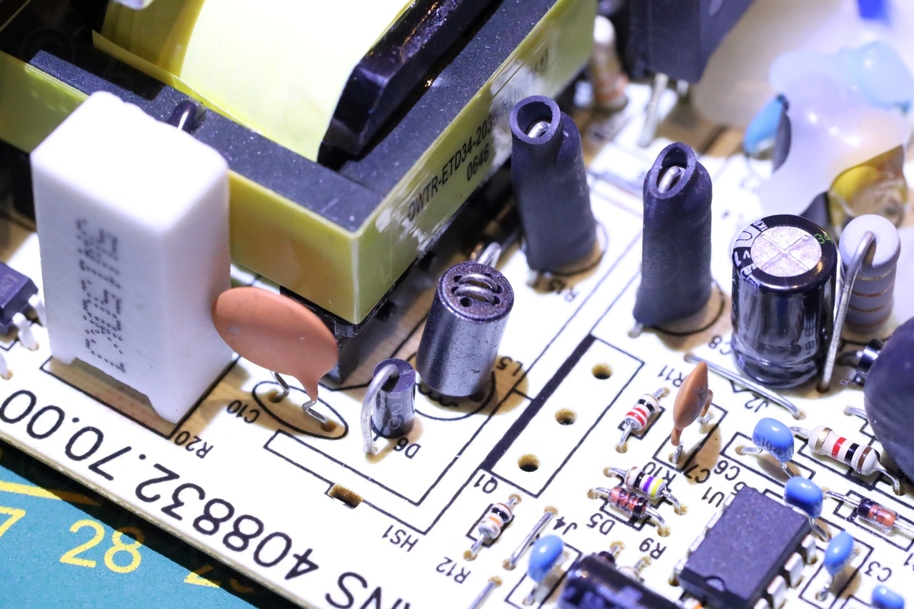
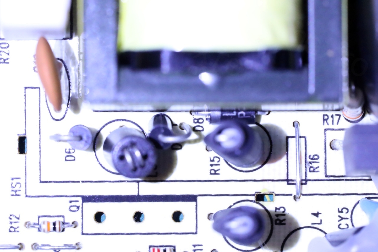
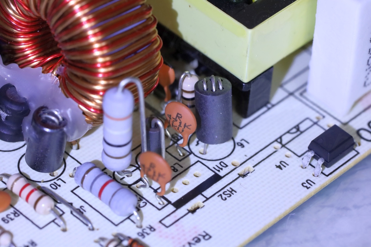
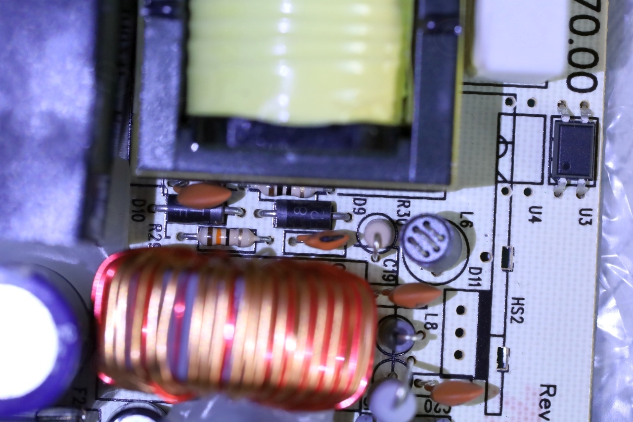
Without schematics, I had to rely on GIMP to try to make sense of the component layout – toggling between the two layers:
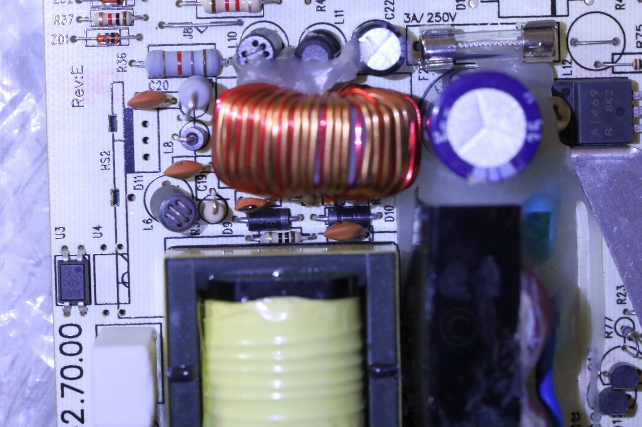
Some components were hidden by the two big heat-sinks around the main transformer. I pulled the two heat-sinks out to be able to reach the parts and test them. But nothing suspicious:
Powering on with a VARIAC
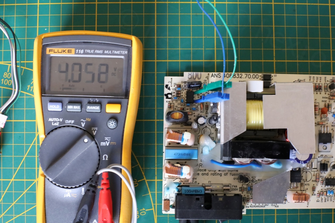
Since I could not find any part that was visibly bad, nor any shorted components or bad capacitors, I replaced the broken fuse with a new 3A slow blow one and decided to softly power on the board using a VARIAC. This is not safe, better would be to use an isolation transformer. However, I have a tiny battery powered oscilloscope (DS203) and without touching anything (since depending where connected, it may be that the oscilloscope is also at line level), I considered I should be safe.
I started with 20V AC having the IR camera ready to see if anything starts warming up on the board. Nothing happened.
I increased the voltage a bit more and, at around 30V AC, I started hearing a faint clicking sound. I was too afraid to get my face close to the board thus I could not tell where it is coming from. It was not a strong relay sound, was it from the transformer ?
The Fluke meter, hooked up to the VCC of the UC3843, was showing that the VCC was oscillating slowly, being above then below the threshold voltage – exactly the same timing as the faint click. Hmmm.
Increasing the voltage even more to around 50V, the clicks increased in frequency. I bit the bullet and rose the voltage to 100V AC. The clicking stopped!
I quickly had a look with IR camera and all seemed fine, no huge extremes. Decided to check the outputs. The 5.2V line was rock stable, but the 33V line one had some ripple. One of the power resistors was hot but stable (around 65C).
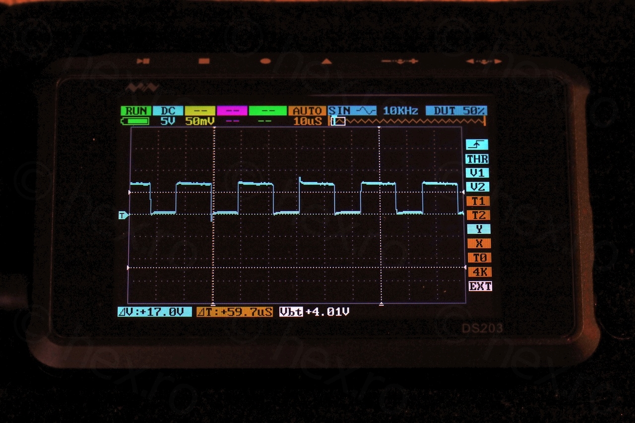
33V line Voltage ripple
Focusing on the 2Vpp ripple riding on top of the 33V line – I found same periodicity (80mS) on the VCC of the UC3843:
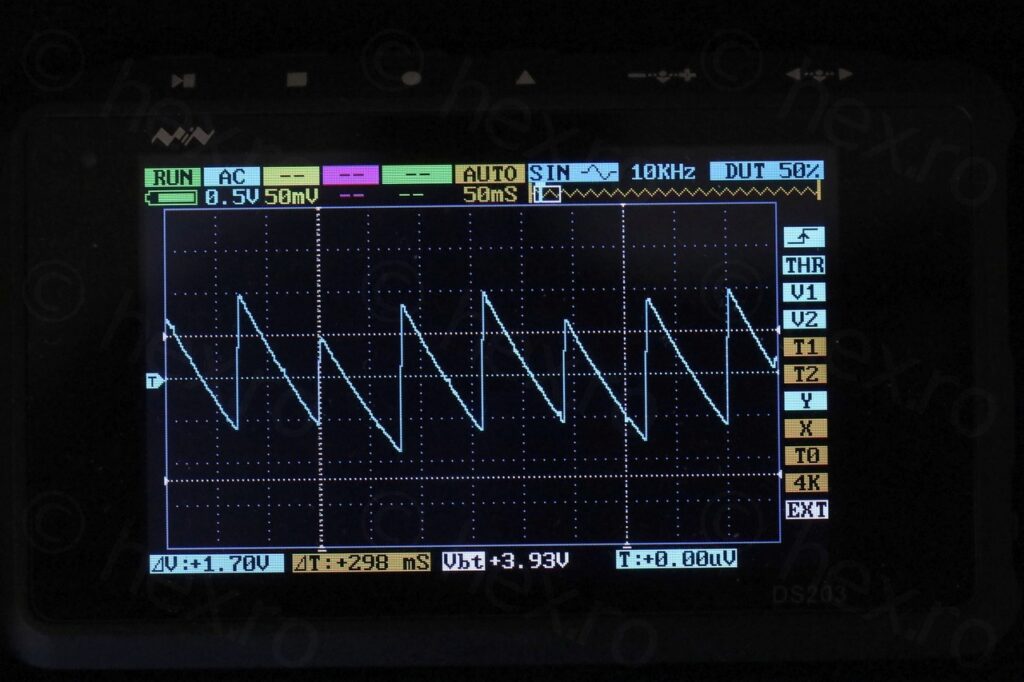
I don’t have enough experience to tell if this is bad, or if this is normal. I figured that loaded with the stepper driver ICs and the motors, the voltage may stabilize more. Without a way to load the power supply down, I took the decision to just try to plug it into back onto the machine to see what’s going on.
At this moment, except few parts that I pulled out to measure but soldered them back, the only change was replacing the 3A slow blow fuse.
Main board issues
I set everything up to power the main board and had the VARIAC set at 100V AC and ready to turn it off if anything scary happened. Expectations were that the machine would light up now that the fuse was changed – hoping the fuse may have been blown while sewing through a difficult material.
First Power On
But no, the machine did not turn on.
I took out the IR camera in the hope I can see something heating up, but by the time I was ready, it was too late. Spotted a thin trace of a white smoke coming from the sides of the machine. Pffffff.
Was it an unobtainium IC that was just cooked ?
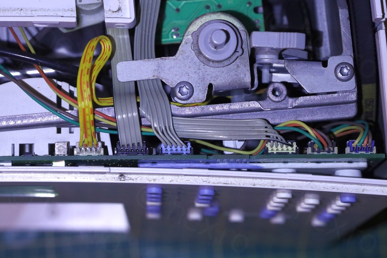
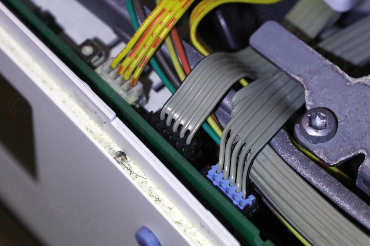
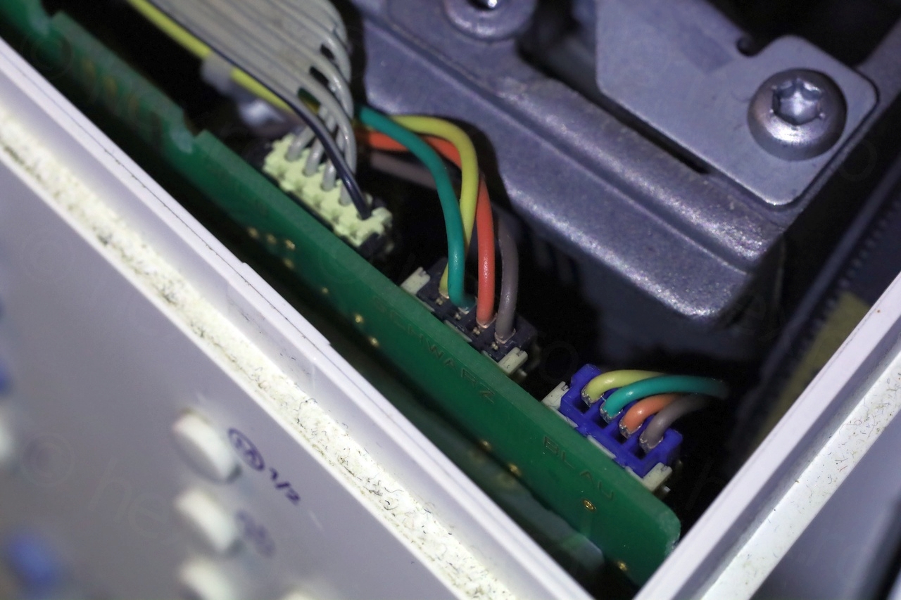
After taking some pics of the wires -so that I know how to plug them back again, I took apart the front panel, aiming for the motherboard:

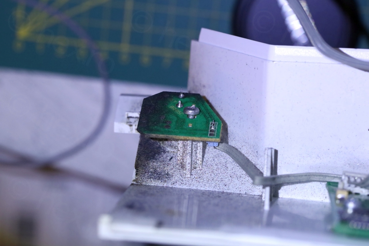
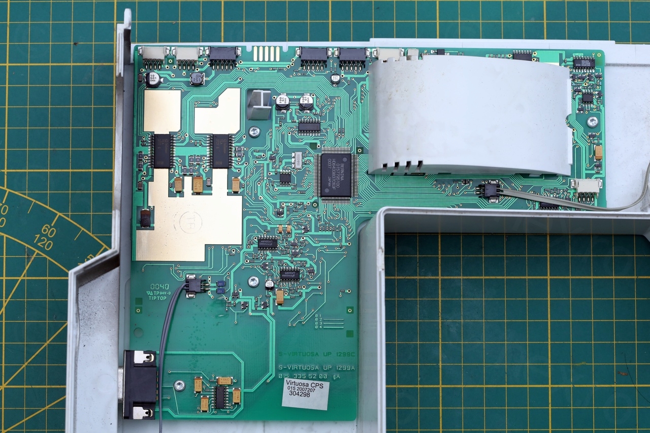
… and what do I see …
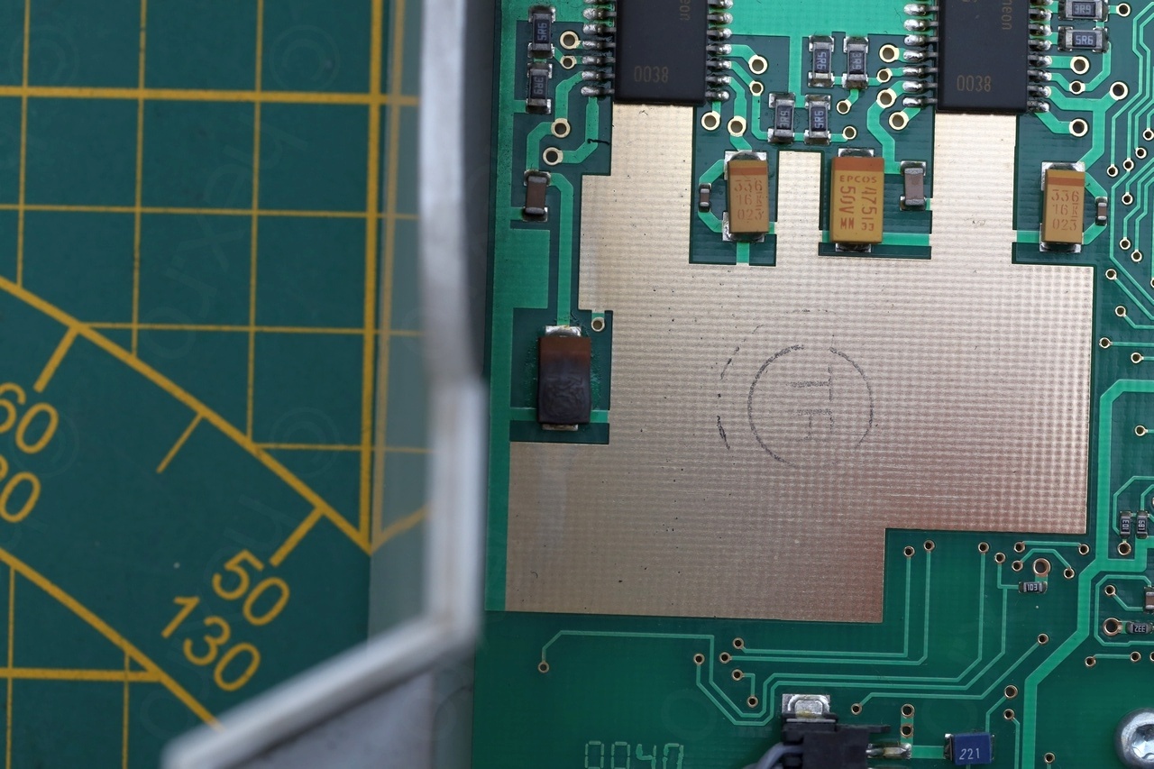

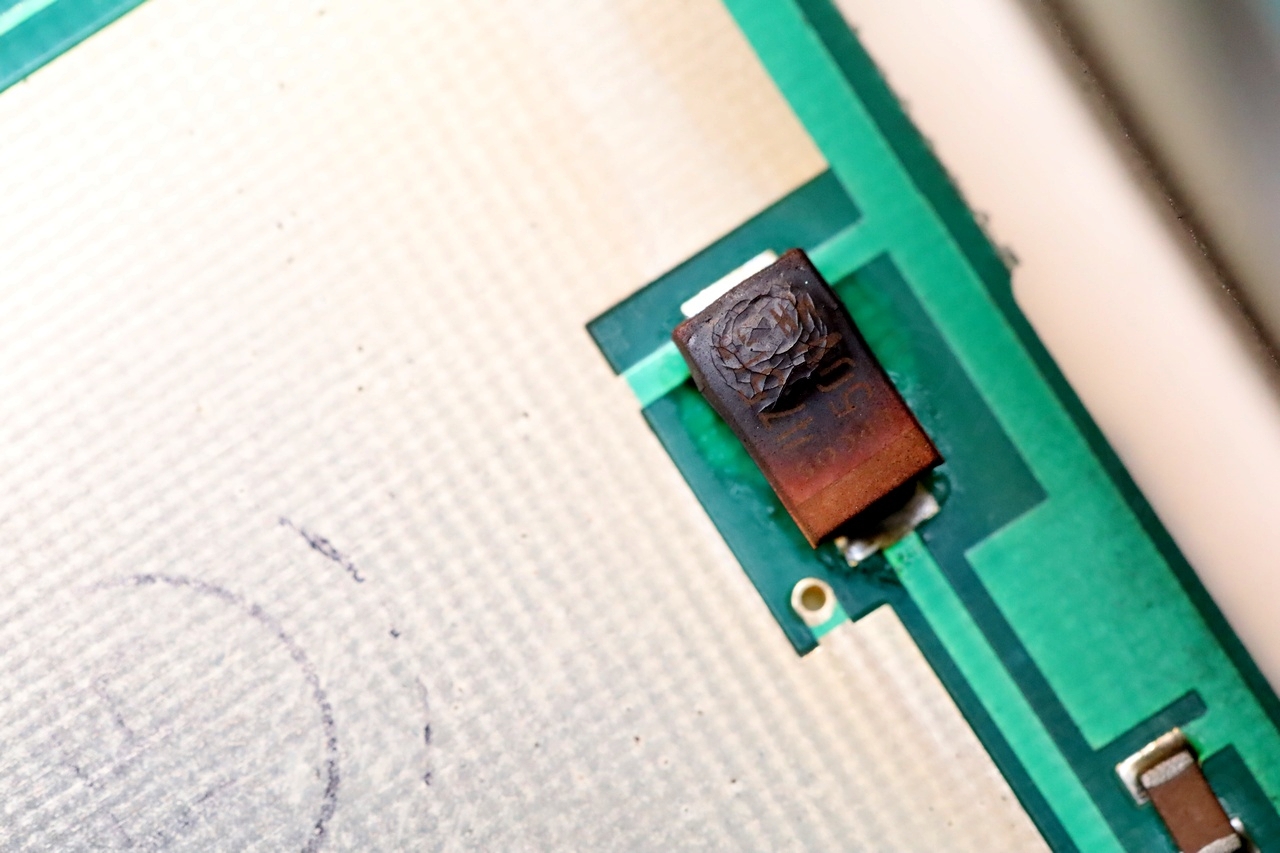
… a cooked tantalum capacitor.
Hopefully, the capacitor value was still readable, 4.7uF @ 50V. While normal electrolytic caps have the line towards the negative lead, tantalums have the line towards the positive lead. This one was was shorted and was across the 33V line, since there was a short from 33V to ground.
Second Power On
I decided to de-solder the burned capacitor. The short was gone. It is a filter capacitor, so the machine can be temporarily be powered on without one in – just to see if this fixes it.
And … things changed. Now the machine was trying to turn on, clicking hard and LCD backlight flickering. I was momentarily both captivated and scared, until another trace of white smoke woke me up. Turned off the VARIAC, and …
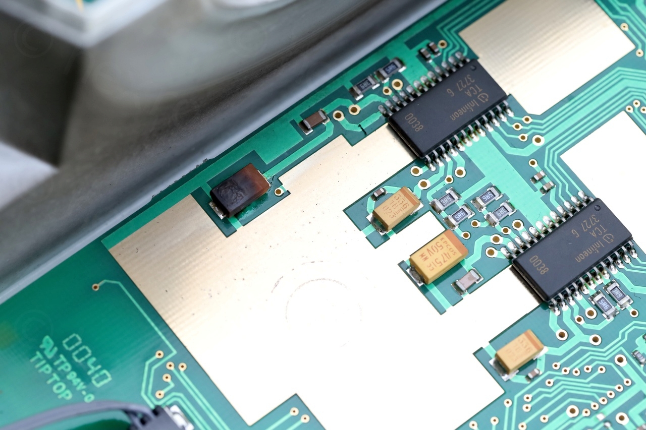
… found the second 4.7uF tantalum in the process of melting down:
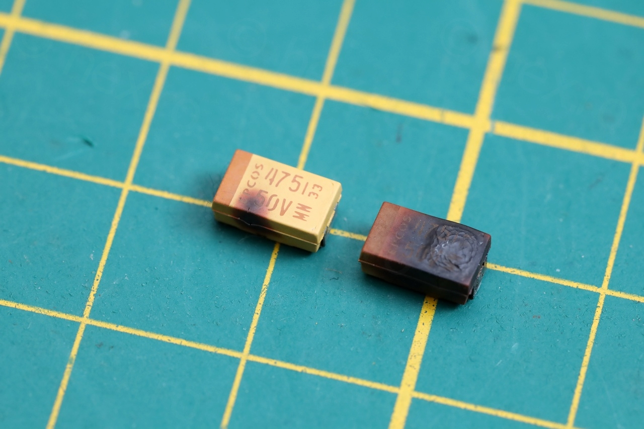
Pffff.
This capacitor was also connected to the 33V line and not shorted before this power on (since the short was gone after removing the first one). It just decided to break down on the spot.
Replacing all electrolytic and tantalum capacitors
With this second capacitor removed, I attempted one more time to power on the machine. This time victory, it turned on properly without any drama.
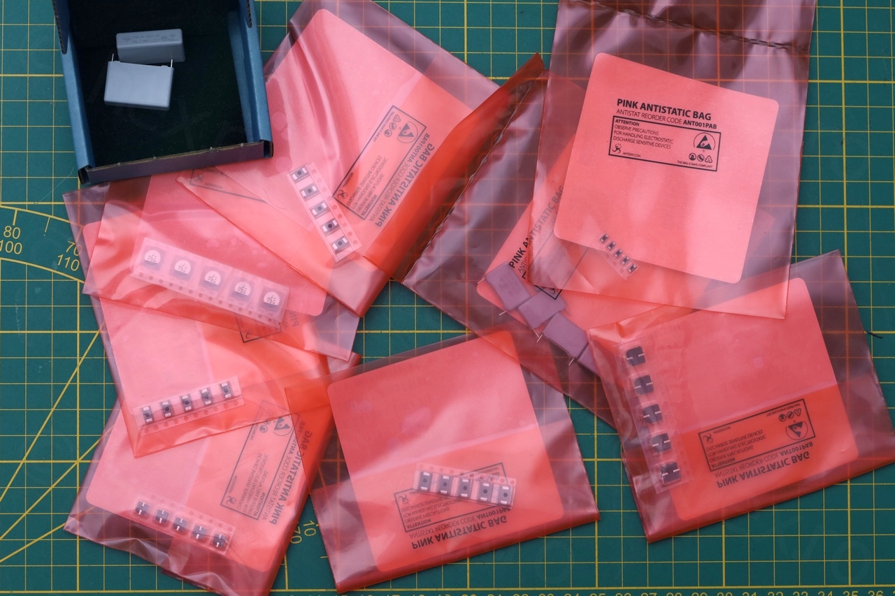
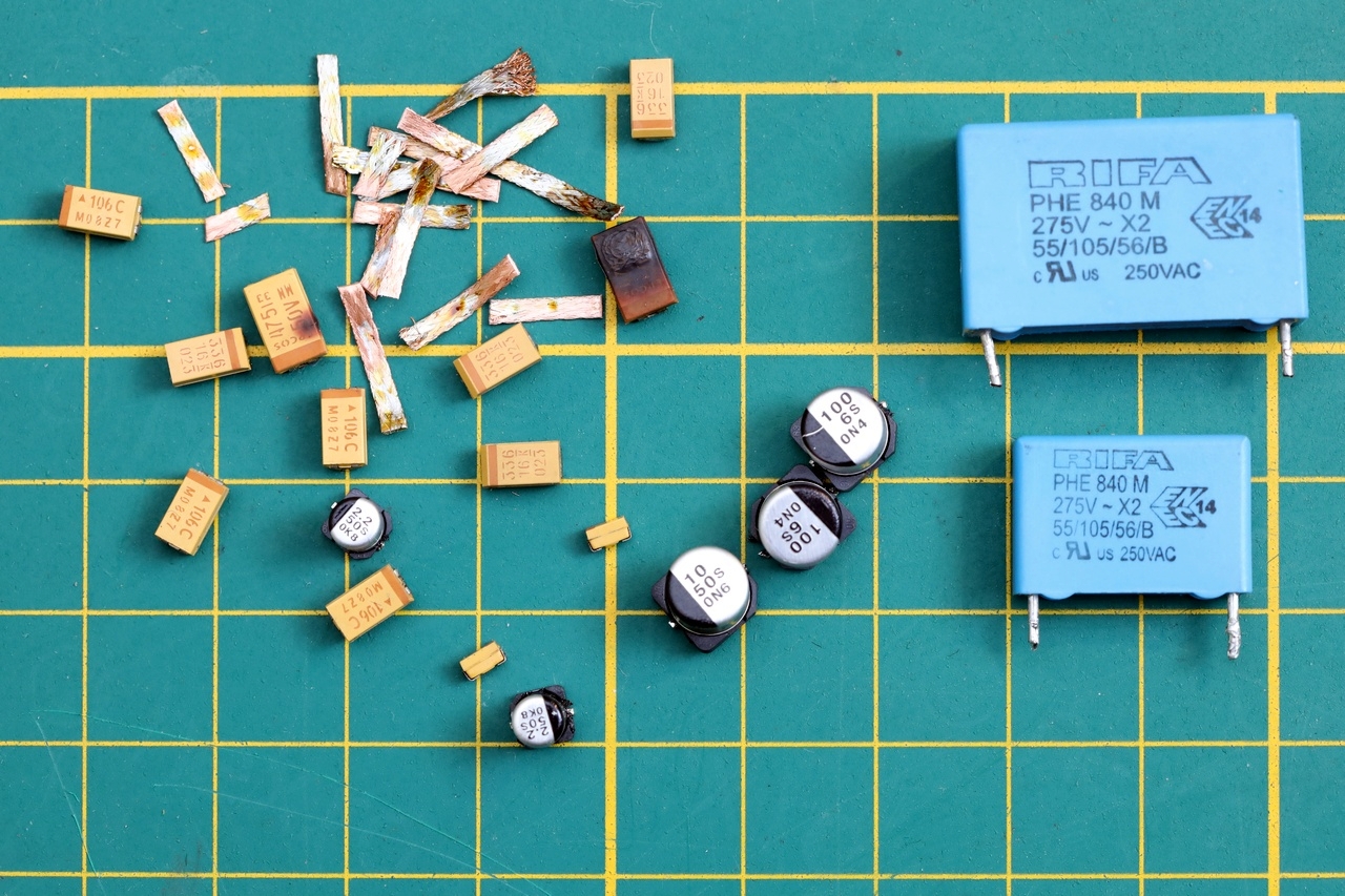
I decided to replace all capacitors to avoid more issues in the future. Ordered a bunch of Vishay and Panasonics for the job. 19 in total, but this should lower the risk if another one decides to stop working or to become leaky and corroding things around. I also ordered replacement for the two RIFA caps on the power supply board. These two weren’t showing any sign of problems, but better safe than sorry.
I didn’t like that the tantalums did not have a voltage rating written on them. In the future, it would be difficult to figure out what to choose. In fact, already two existing small tantalums (very close to LM324 IC) didn’t have their voltage rating specified either – or maybe I don’t know how to recognize them ? Bound by their physical size and capacity, I could not see anything higher than 35V. So that’s what I replaced them with.
I replaced the following 12 tantalums:
- 4.7uF @ 50V (2 of them)
- 33uF @ 16V (4 of them)
- 10uF @ 16V (4 of them around the MAX232)
- 0.47uF @ 35V (2 of them, tiny, the ones next to LM324 IC)
The electrolytic ones were:
- 10uF @ 50V (one)
- 2.2uF @ 50V (2 of them)
- 100uF @ 6V (2 of them)
The safety ones, on the main SMPS board:
- 470nF @ 250V, Safety Capacitor, 25mm (although the spacing on the board is less, maybe 24.5mm)
- 100nF @ 310V, Safety Capacitor, 15mm
Cleanup and Wrapping it up
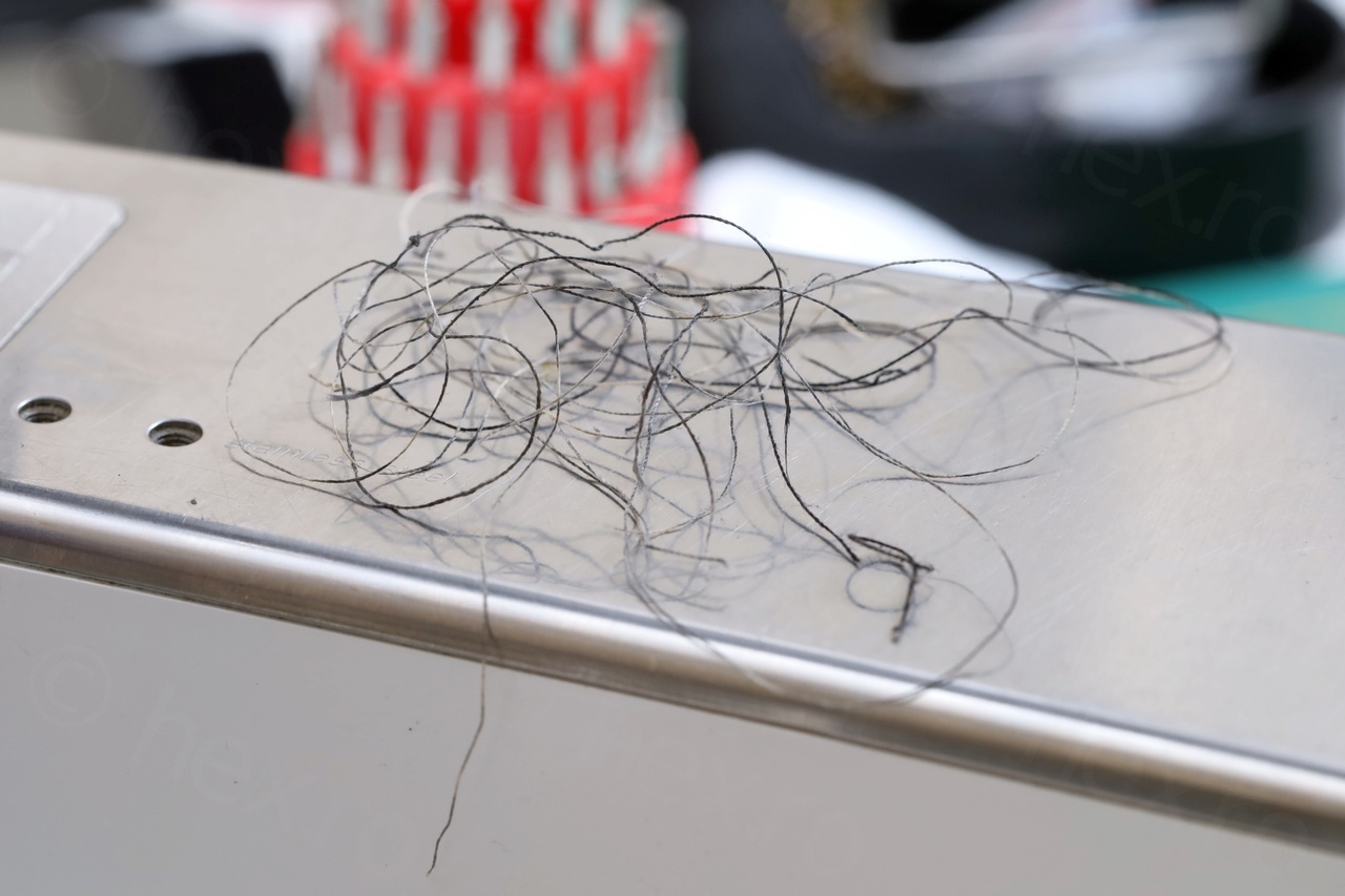
Since I had the machine apart, I decided to have a visually inspect the mechanical parts. Not knowing what to do exactly, just looking. And surprise, I found a lot of thread spooled up around the needle bar connecting link.
Thread spooled


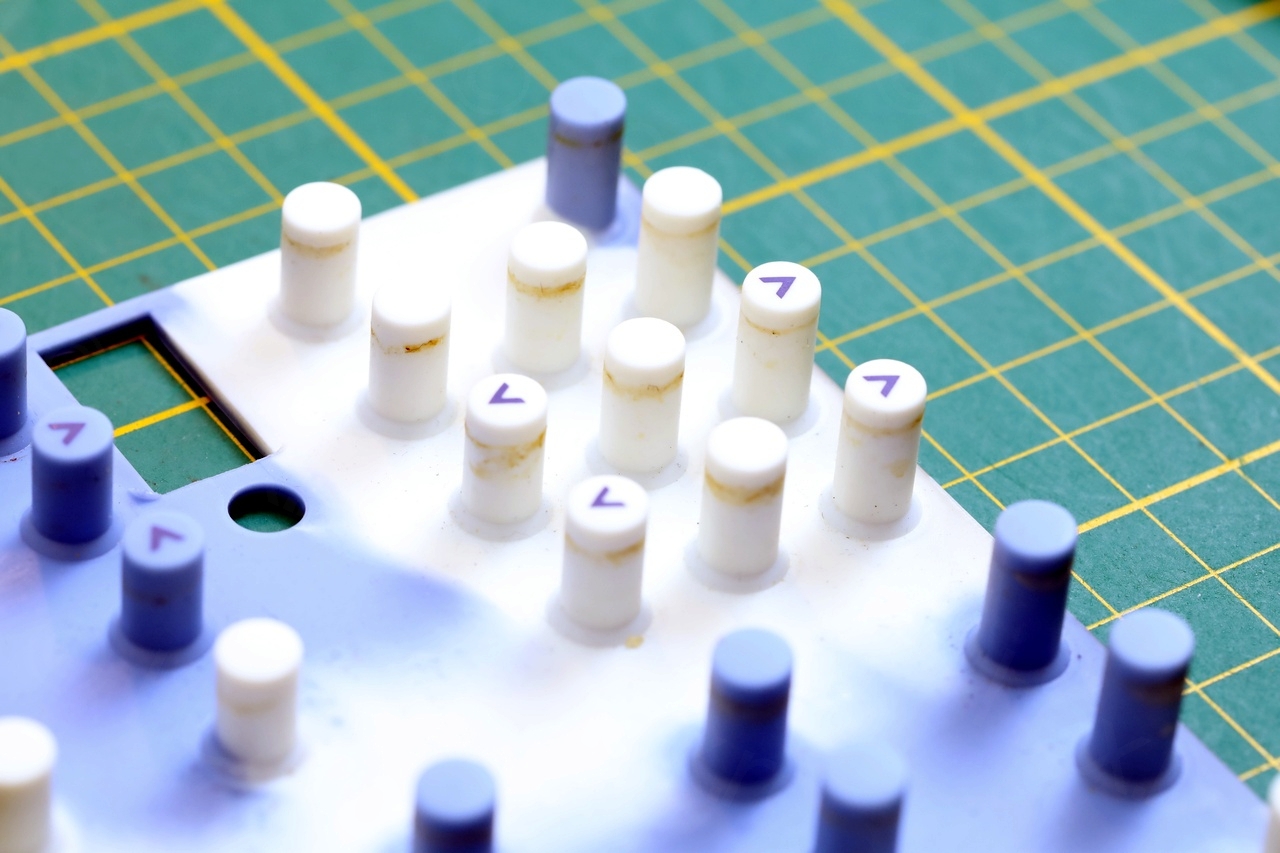
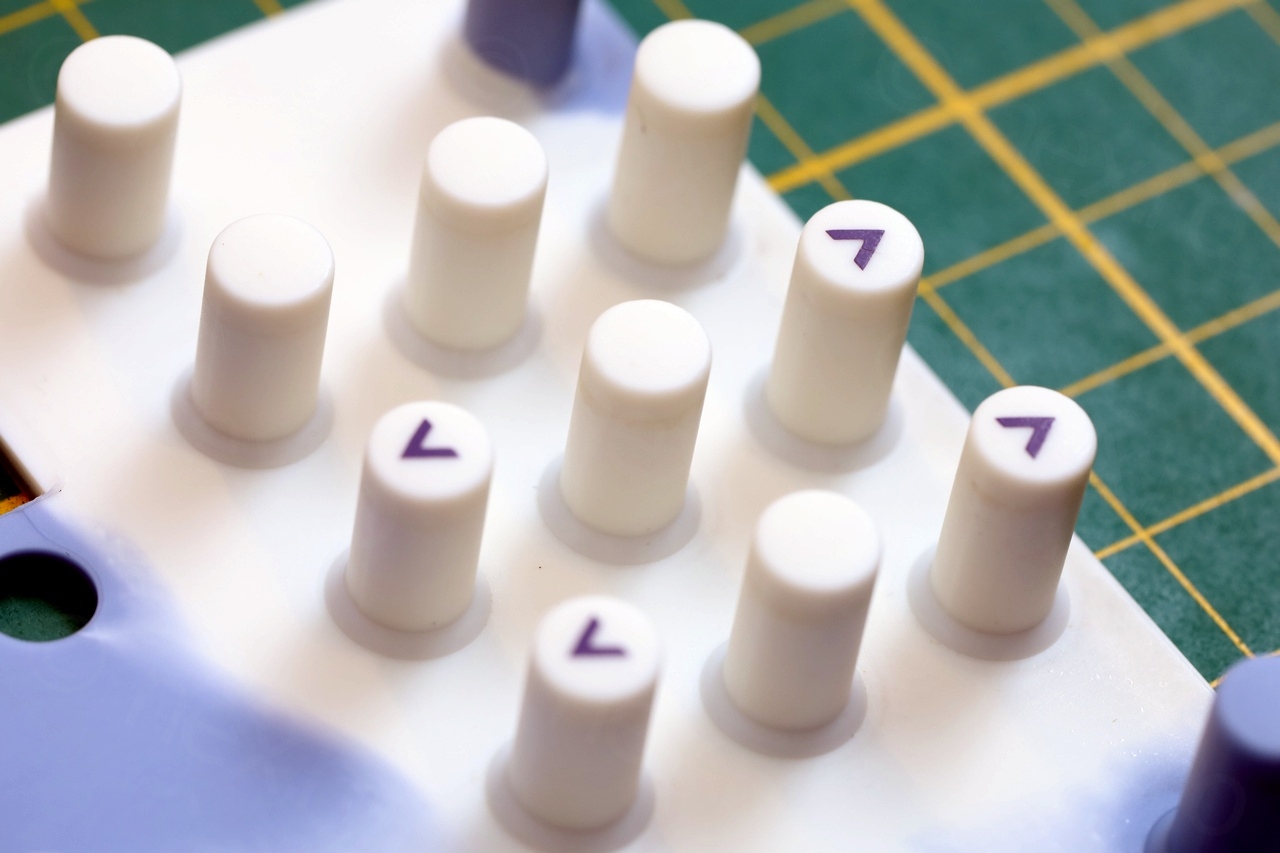
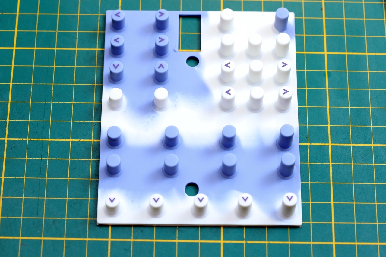
De-greasing the buttons
Some before and after photos for removing the yellow crud on the buttons:

Light bulb replacement
The machine takes a 12V/5W wedge base light bulb. As luck would have it, the bulb gave up too. In the initial video above, it is still the original bulb which goes very bright when turning on, then very low output, then again a bright flash when turned off. I settled for Osram car bulbs, having the same ratings:

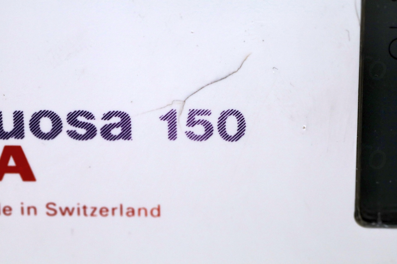
Plastic cracks
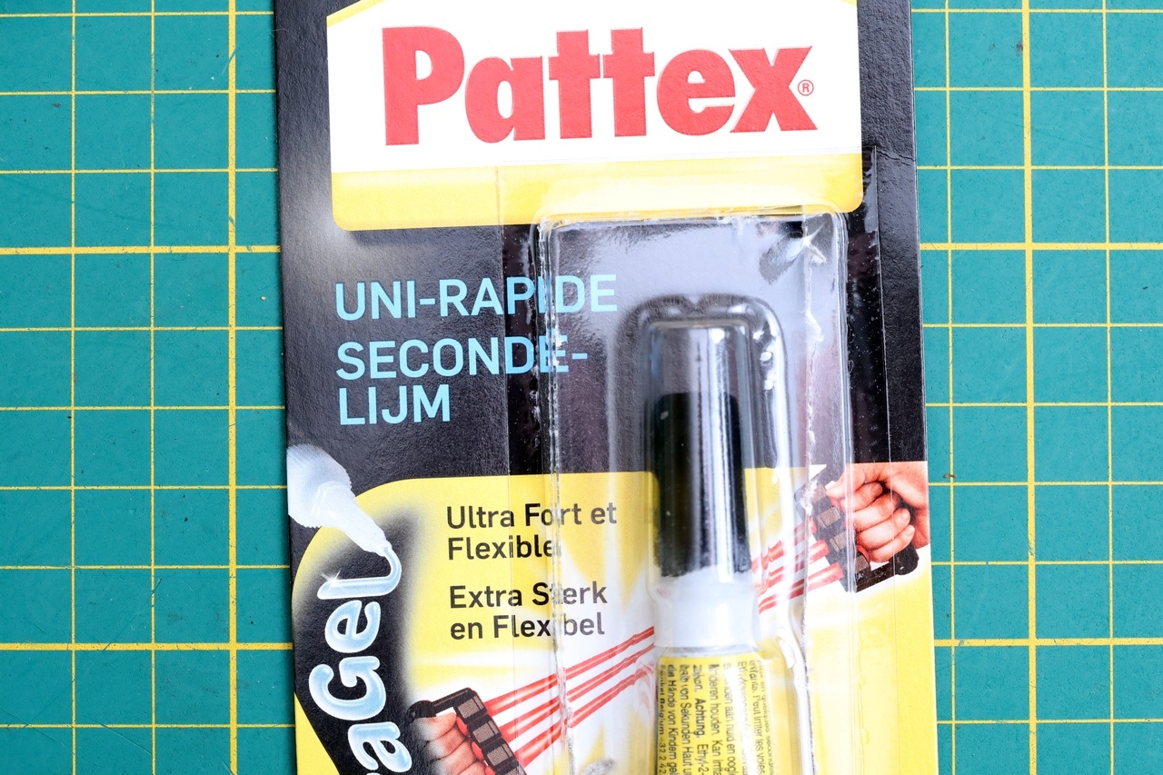
I used some superglue gel to try to keep together the plastics that were cracked around. Unfortunately, I still heard a crack sound when tightening the screws down .. probably 1-2 more opening ups of the machine, and the holes will have to be replaced with a 3D printed equivalent.

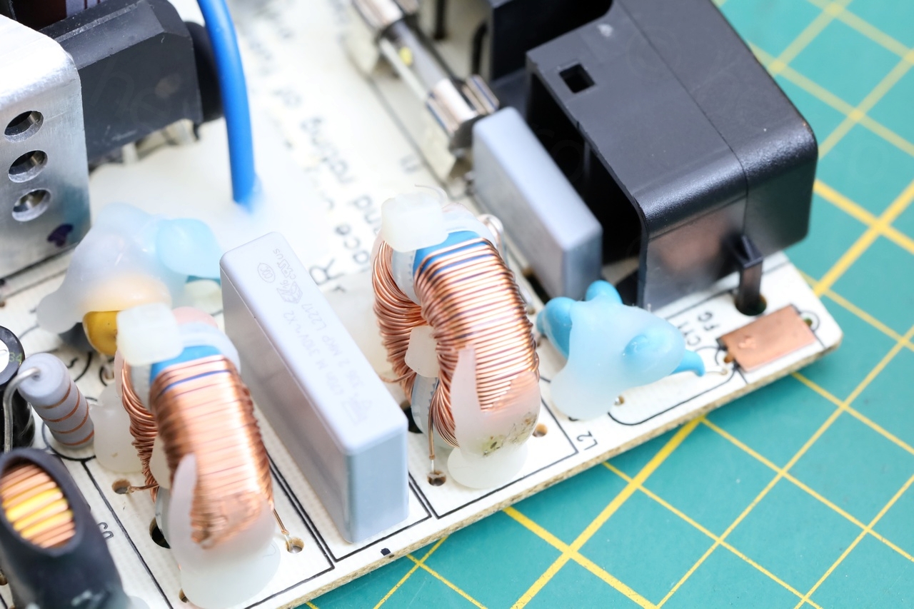
Loose large inductor
The large inductor under one of the shields became loose from the silicone that was poured over it. I figured some hot melt glue would contribute to the anti-vibrations – I don’t expect it to become very hot during the normal running of the machine. I also didn’t have any electronics safe silicone.
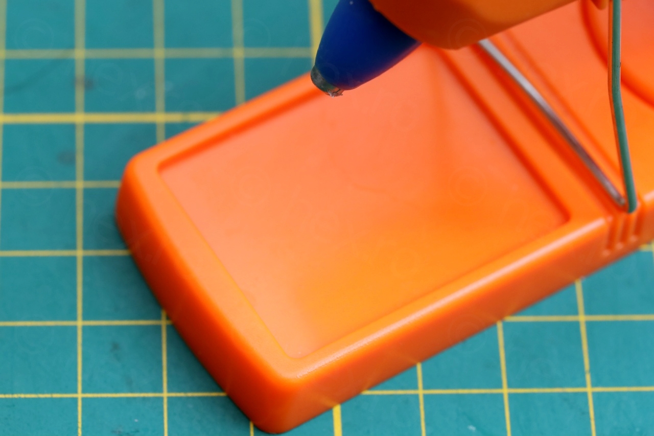
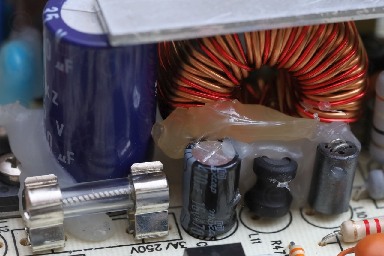
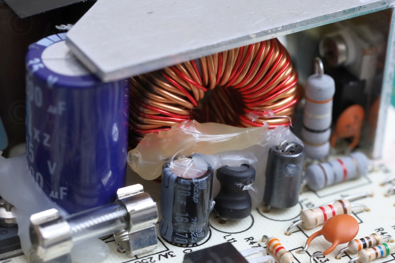
Not sure if this is a good idea, but … only time will tell.
Remarks
Among first Google searches about Bernina sewing machine not turning on, there are some advises suggesting to leave it “on” for a long time, to somehow “charge” it. I am not sure what could happen during 1 hour to get the machine to boot. Maybe the board heats up and dilates enough so that some minute cracks (or cold solder joints) finally start making contact ?
Given the experience with the tantalum capacitor smoking out, I would not leave a machine up for hours just to see what is happening, especially with the risk that it may be unsupervised.
However, I also found interesting posts such as the one below, related to Bernina Activa 130: http://repairsewingmachines.blogspot.com/2014/05/how-to-repair-bernina-activa-130.html.
I am also surprised by the lack of service manuals available for free. Service Manuals for most older radios are easily available online, but not for Bernina Sewing machines. The board looks very professionally done, many ICs and voltage references, way better than the datasheet sample schematics for the ICs. Everything is labeled properly, spaced out and easy to measure.
Results

Interestingly, I found out that the initial startup calibration sound (the “brrrr” it makes when turned on) is also called Bernina “burp” or Bernina “purr”. This machine makes two burps in fact. One is when turned on, the second one is during the first stitch when the needle reaches the “up” position. Then never again in the same session of being “on”.
If the machine is turned on with the needle in the down position, it makes the startup “burp” upon being turned on – but the second “burp” comes in only when the needle reaches the top position in the first stitch. Even when hand cranked.
Anyway, here’s a video with it running 🙂 you will see I hesitate a bit on the first stitch, to give it time for the second burp:
The machine needed a new fuse and two shorted tantalums replaced. One more item saved from the dump.
Lee Kroencke
great recovery.
clear explanation and illustration.
Keith Winsett
working on the same model right now and the tantalums were fried on this one. Thank you for sharing this as it helped point me in the right direction. Just like yours, the power board checked out fine.
Enzo Coquelle
Hi,
I’ve just repaired mine thanks to your guide !
Thank you !
perry yoshida
The MOST useful article I’ve found regarding a electronic controlled Bernina I have read. I am currently working on an Artista 200 and there is very little information about the internals of this machine. It looks like technical information about the Bernina machines isn’t shared to keep Consumers in the dark when problem arises. Considering the ages of many of these machines I’m surprised there are no google images of a Power supply board with the common failure components circled for reference. With many of these Bernina no longer being factory serviced technical information is needed for many of these serviceable machines.
AS mentioned in this article I’m surprised there is NO Schematics of the circuit boards for these machines.
Greg Moore
Absolutely have to say thanks! Bought a “won’t turn on” 180 on the chance this is where it was going. Found nothing on 33v when connected, good 33v when plug off. Pulled the S print, found a black cap, same one you found. Pulled it, tried machine, it burped, then quiet little tick and shut down. Took a bit but found a second one shorted, now she boots fully and stays up.
More work to do but it’s a working machine and your article saved me a ton of diagnostics time!