


Introduction
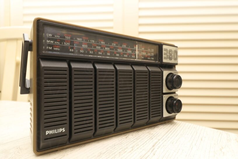
I found this radio at a flea market and decided to buy it along with some other very old parts that were around:
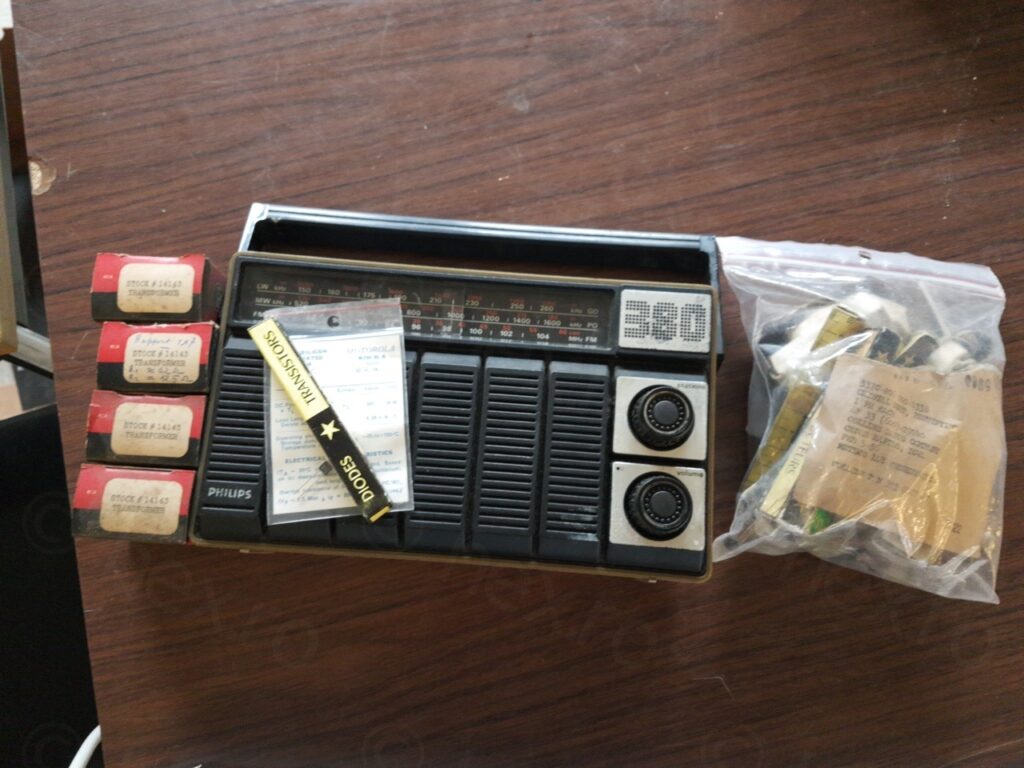
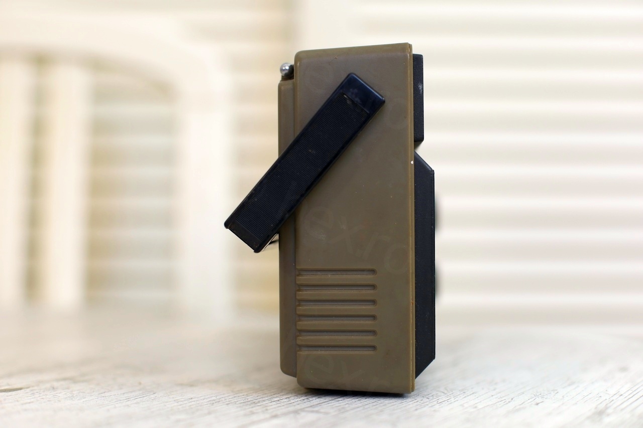
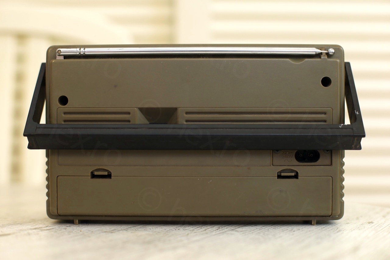
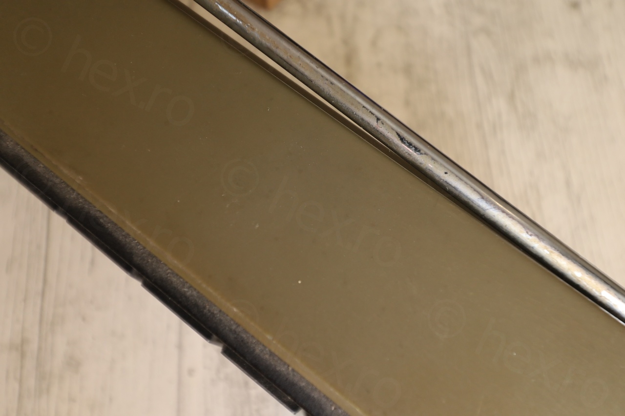
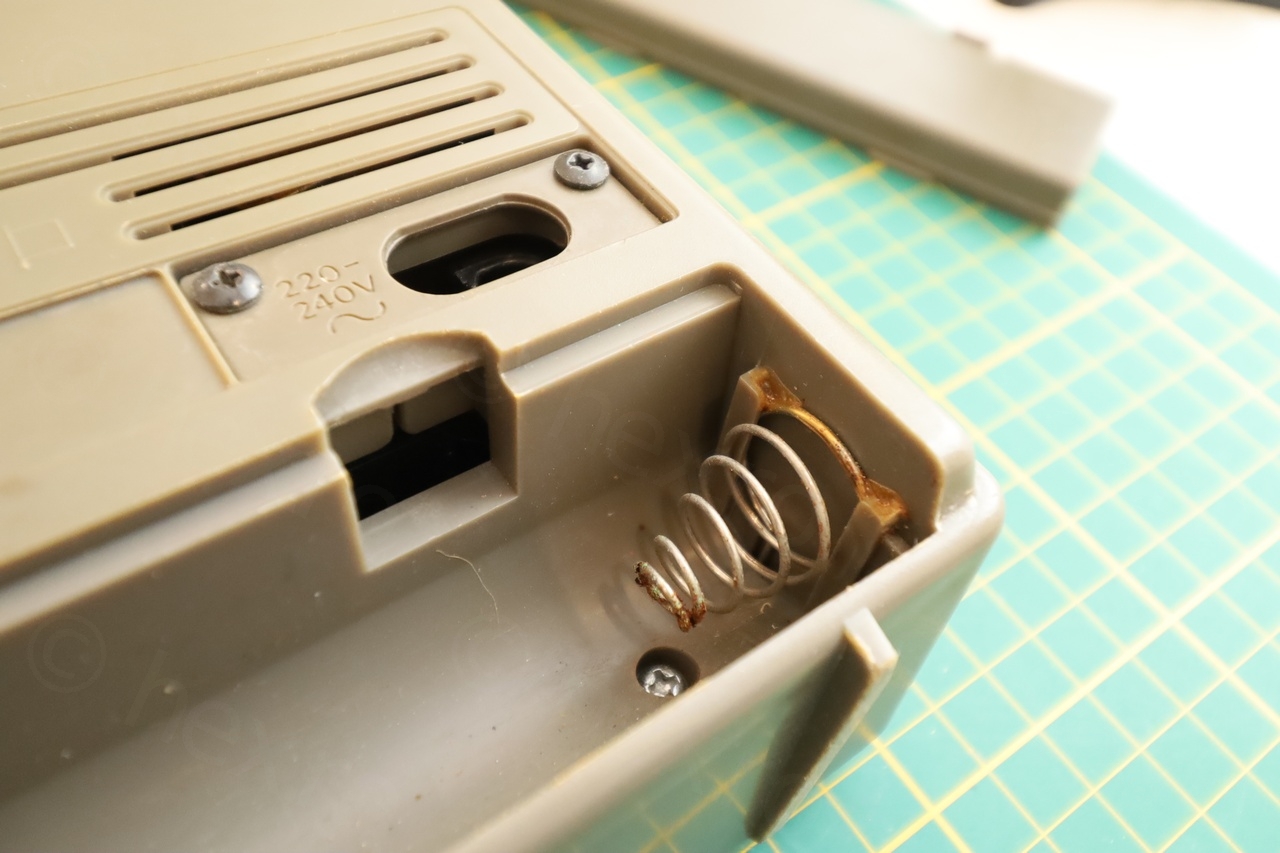
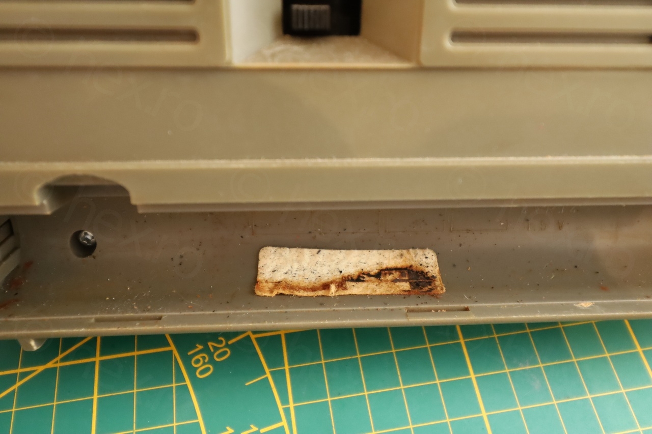
Once home, I was able to inspect it more thoroughly. Covered in some hardened dirt with accumulated dust – was it a kitchen radio then moved to the garage ? There were two missing parts: the holder of the FM antenna was snapped. Also, the label was unreadable due to probably batteries leaking.


Upon testing to see if it actually works, I discovered that there were two problems:
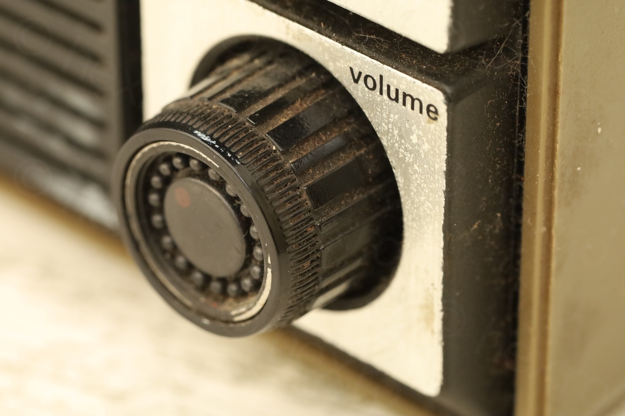
- Volume very loud even if the volume potentiometer was at minimum
- No MW / LW reception, just hiss – volume had to be cranked to max
Restoration
Luckily I was able to find the schematics online – but the scan quality is not very good – some component values are very hard to read. This radio is a better variant of Philips 270 (90AL270) which misses the LW band, but the schematics of 90AL270 are very well scanned – this helped a lot when fixing the volume issue.
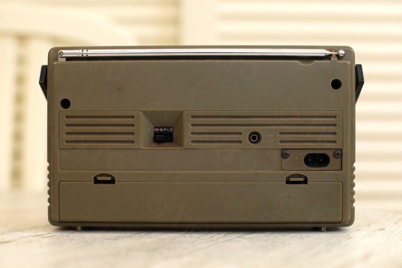
Another interesting thing is that the FM band is limited to 104MHz even if this radio was sold in Europe and found an interesting discussion about the history of the radio here.
Opening up
I made a mistake when opening the radio. You have to pull the front from uni-body case of the radio. It is fairly easily using some plastic prying tools. But when I got the top part I bent it too much trying to take it out – and I snapped two bottom retention plastic pins.
The takeaway is that when lifting the face of the radio – you have to unclip it both to the top and to the bottom, then lift it straight up. The J&B Weld glue held well, I was able to take it apart again – but this time paying attention just to lift it straight up.
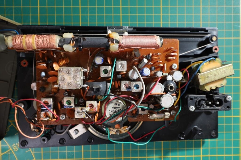
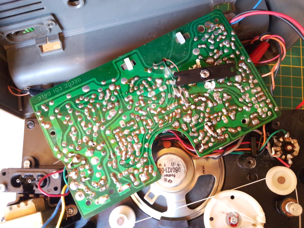
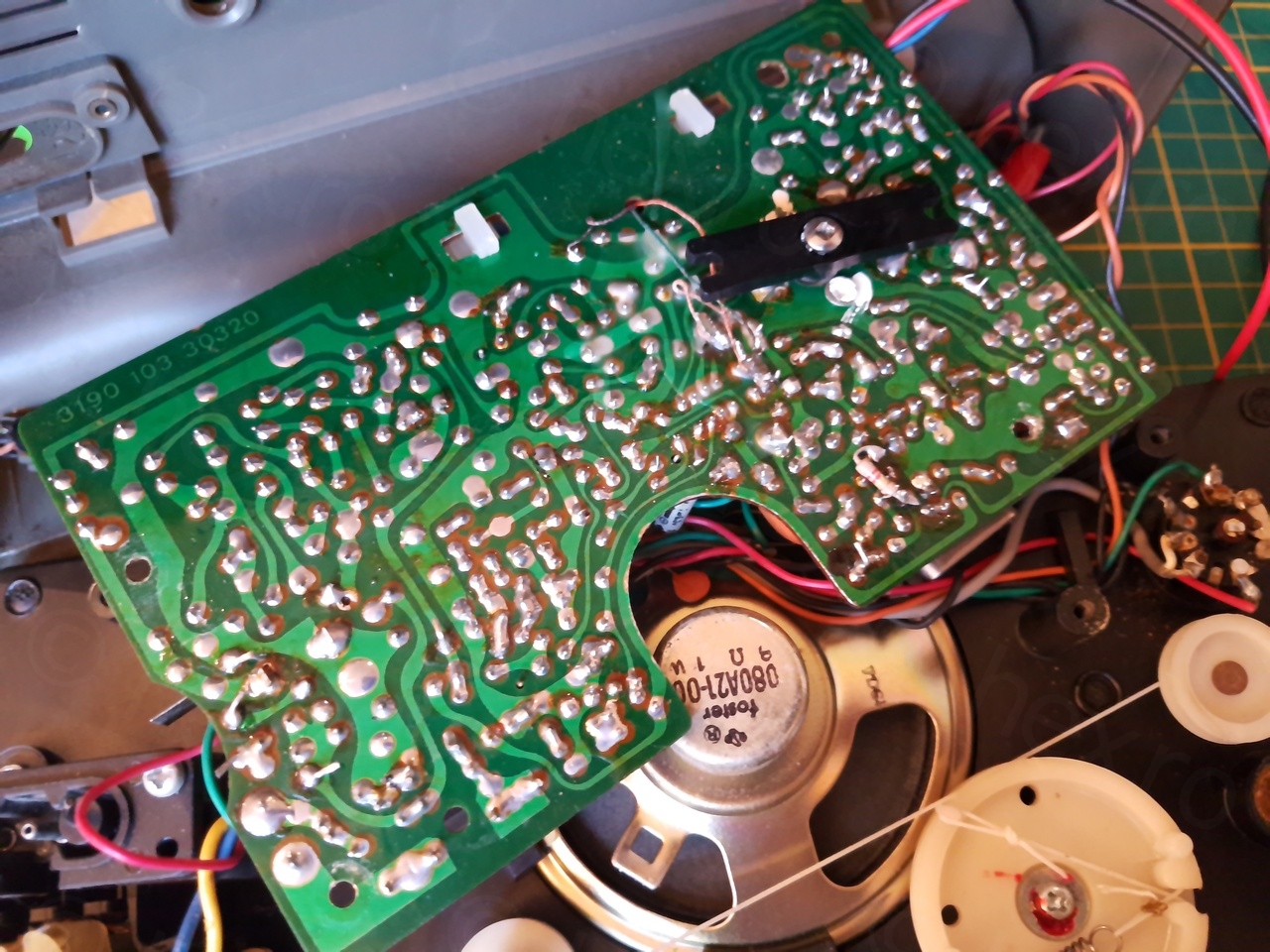
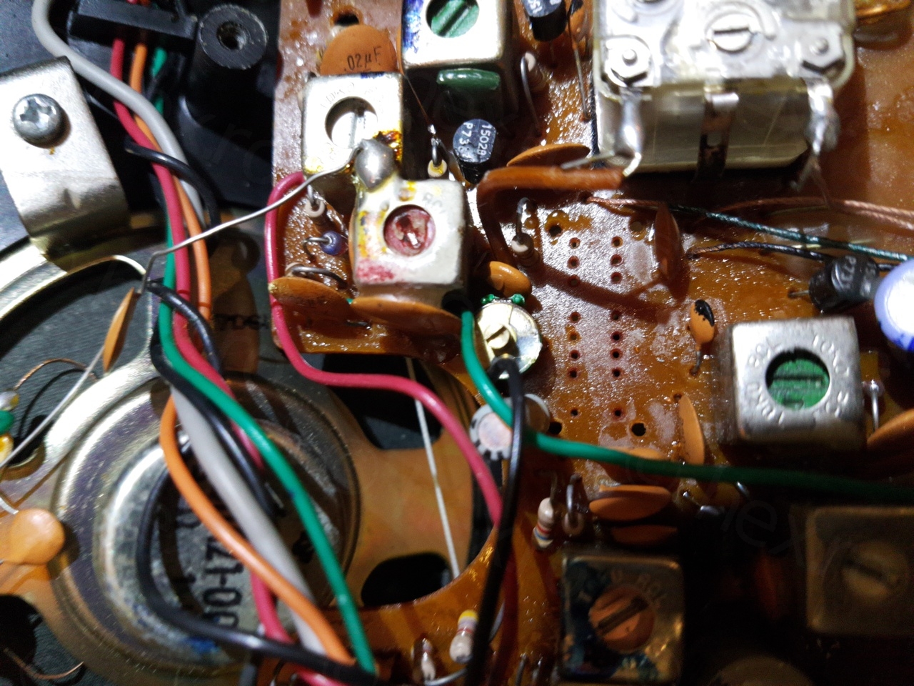
Inside, the circuit board was very clean:
Fixing the MW / LW reception
Voltages on the transistors were perfect, what to do ? I’ve resisted the urge to swap the capacitors – unless I would diagnose one as faulty – it is nicer when parts still work. I did measure few in circuit and had acceptable ESR.
By just touching the base of the transistors involved in the MW/LW path, I reached to the base of TS4 and I could still hear cracklings in the loud speaker. So what could still be wrong ?
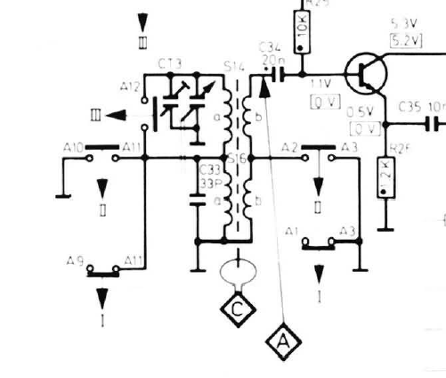
Even the point marked with A (the capacitor before the base of the transistor) was still allowing signals to enter the amplifier chain so where was the problem ?
I realized that the only thing that may worth a check would be the band switch – it was connecting various parts of the AM antenna to ground or disconnecting it (for FM).
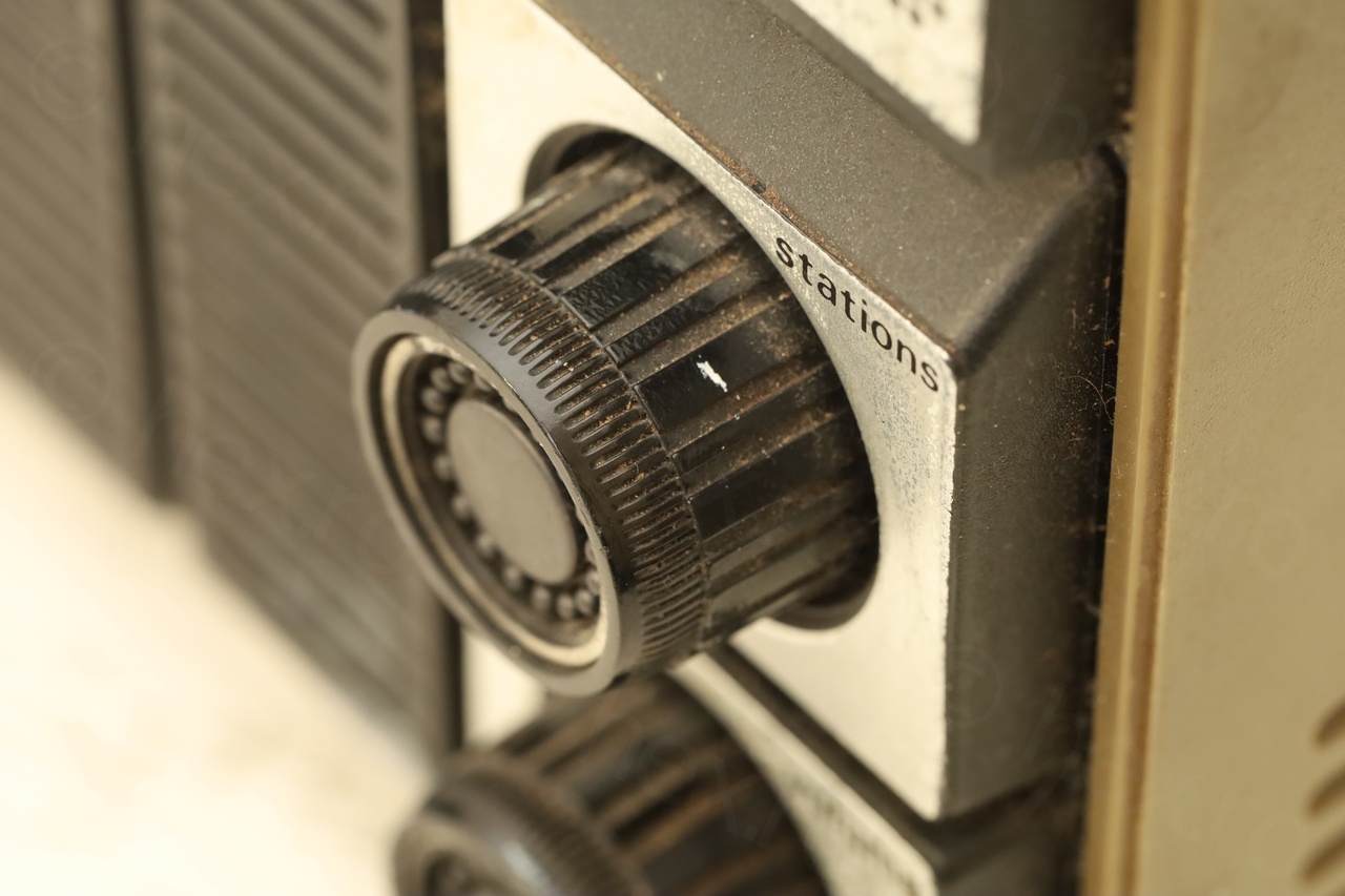
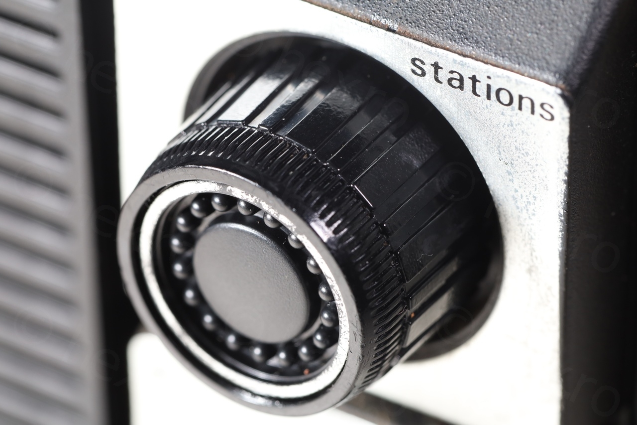
First step was to apply copious amount of contact cleaner. This made the band switch impossible to slide. It got so stuck that I was afraid I may damage it when trying to switch bands. However, there was a slight improvement, the LW band started also to be very loud! Not the AM. Also, discovered that the switch was very touchy:
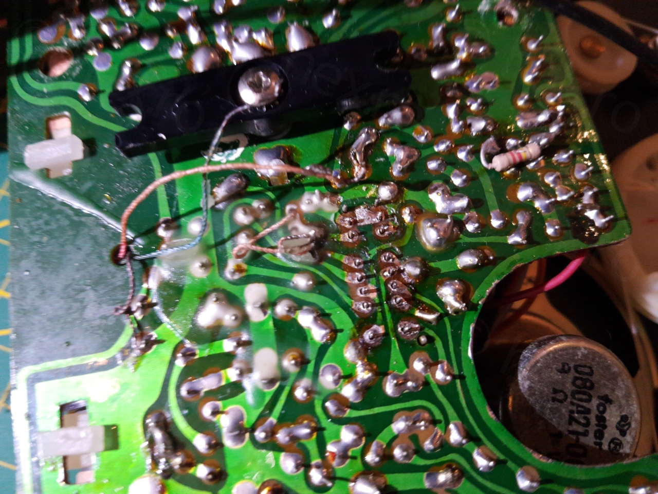
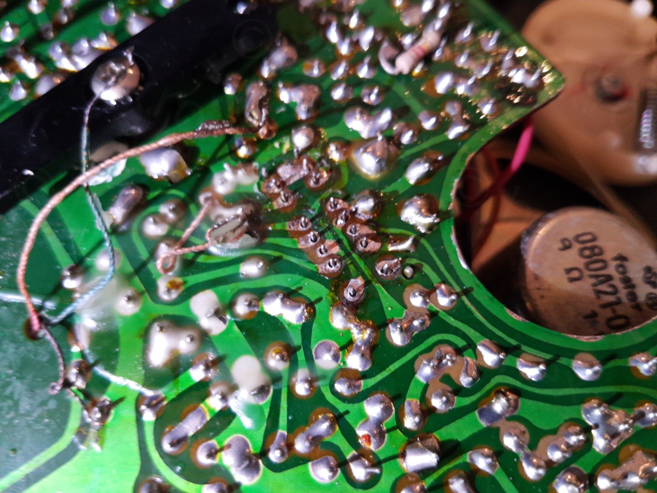
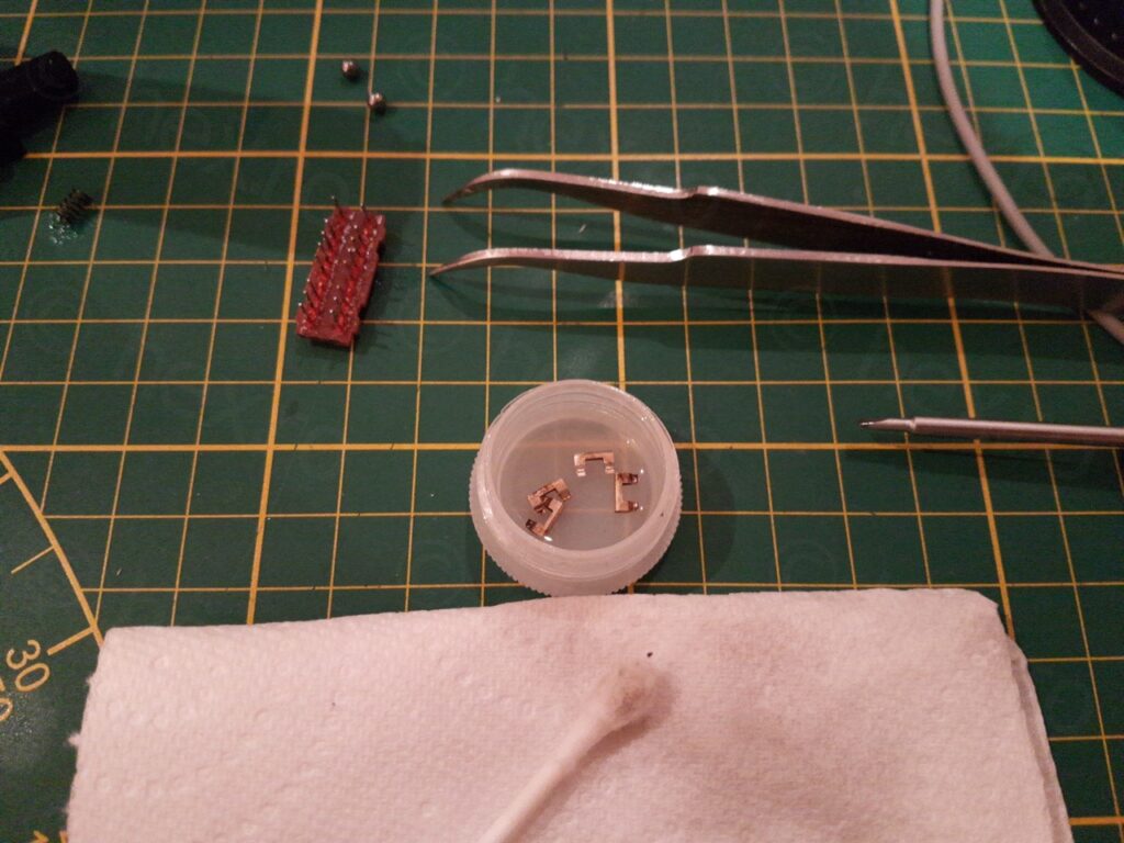
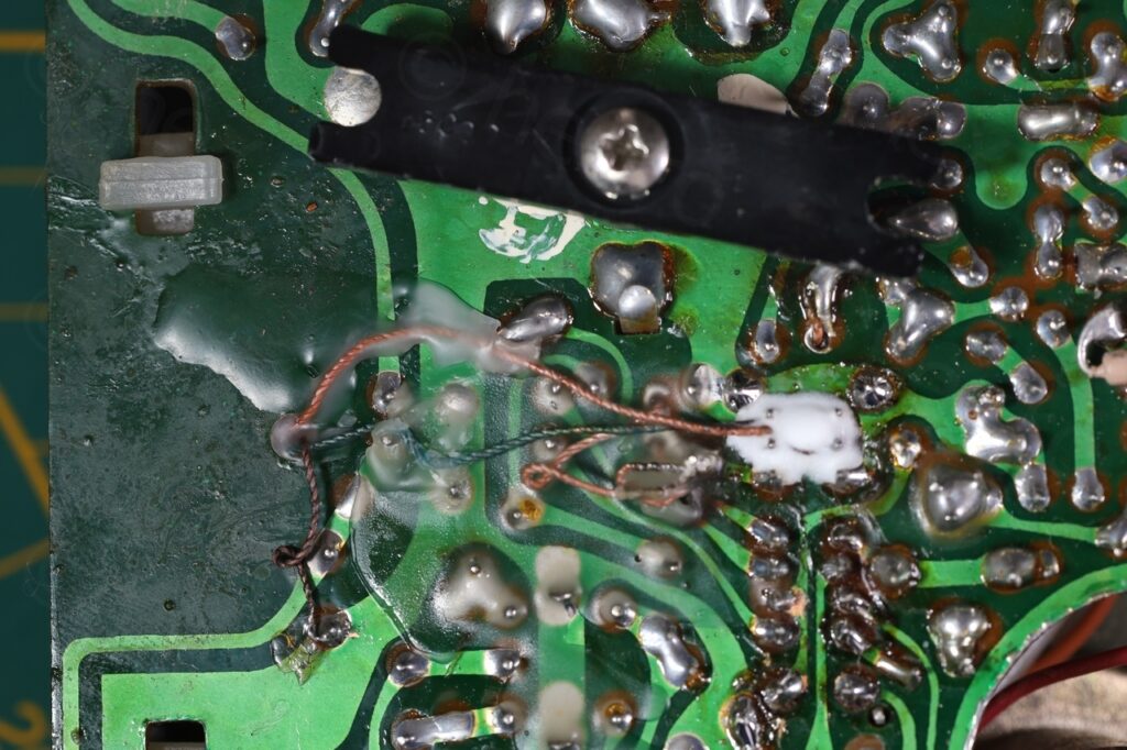
The only way to proceed was to desolder the band switch and try to see what is going on inside. One pad unglued itself from the board but I managed not to break it – a lot of care was needed. I used an S-998P electric desoldering gun.
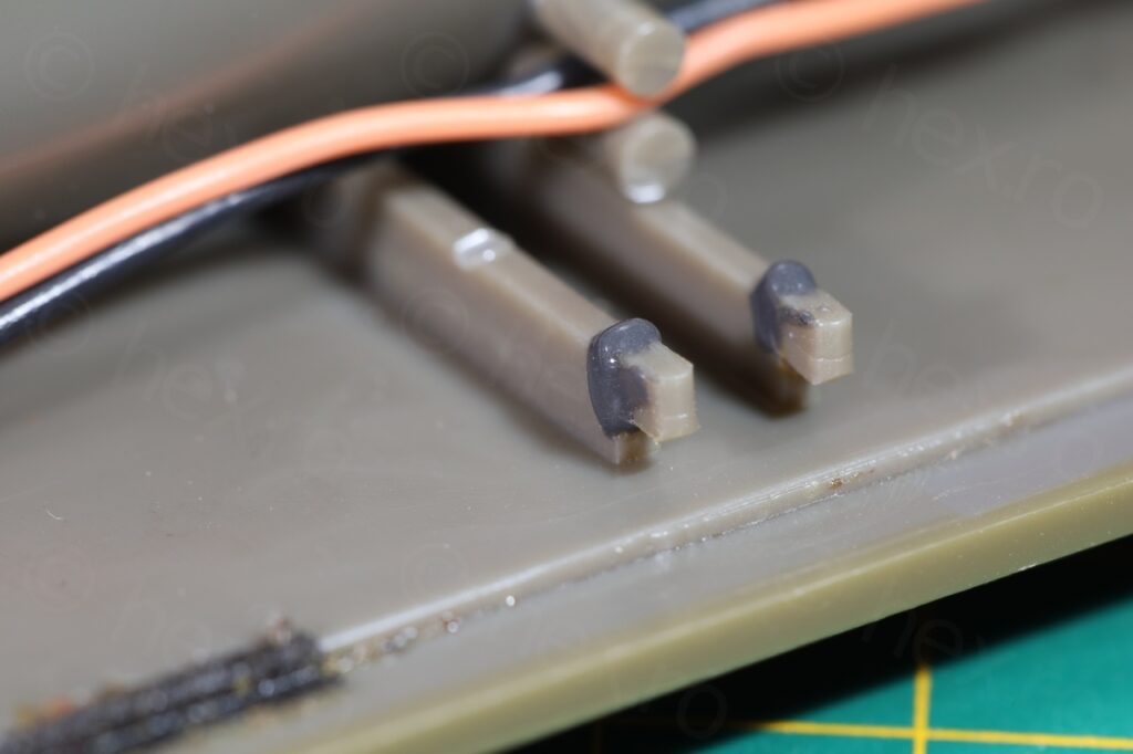
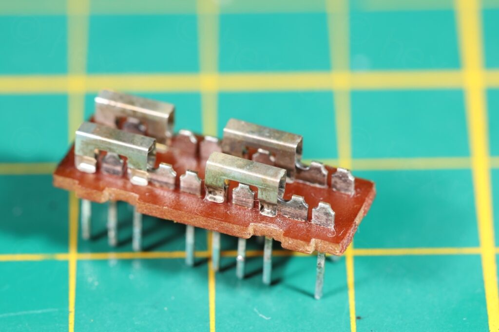
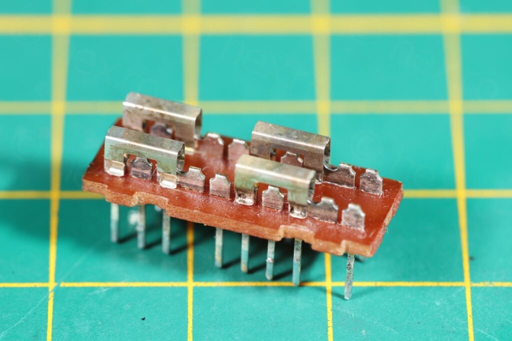
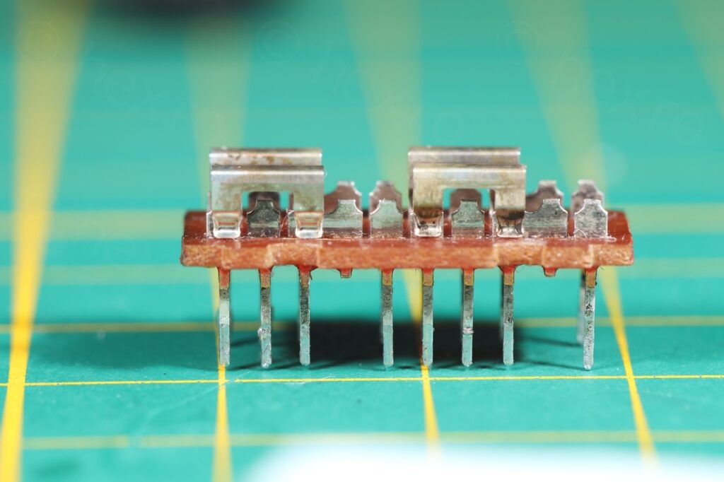
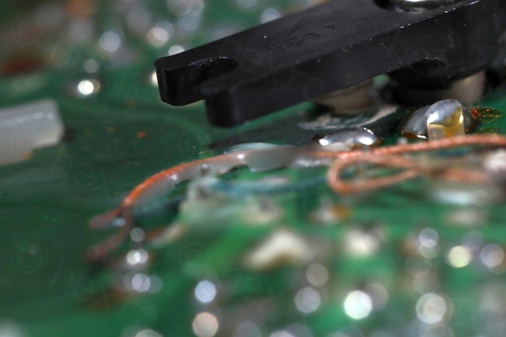
Prying the 4 tabs off, I discovered everything was tarred – the pins were so oxidized I started wondering if the contact cleaner had any chance ..
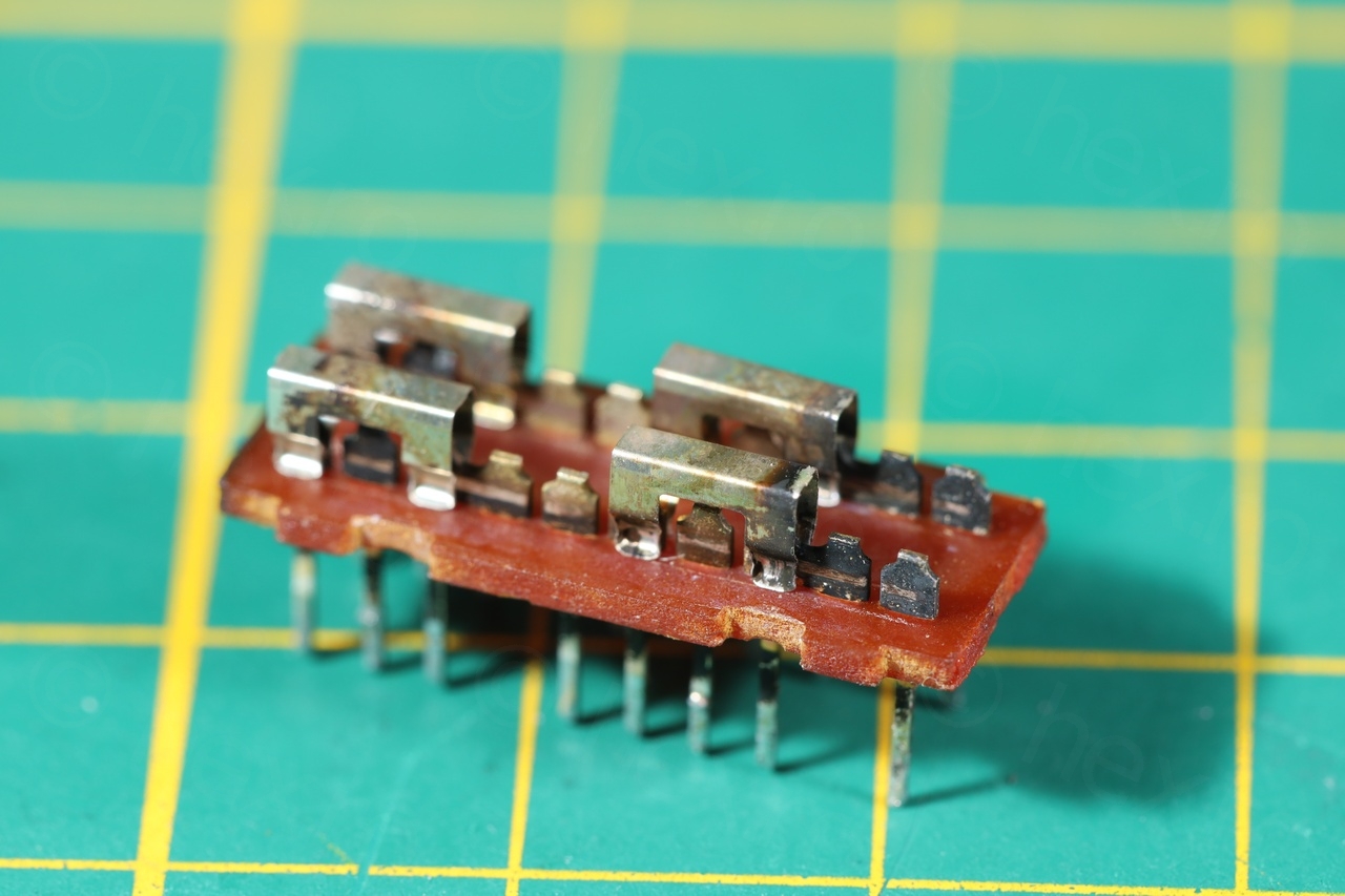
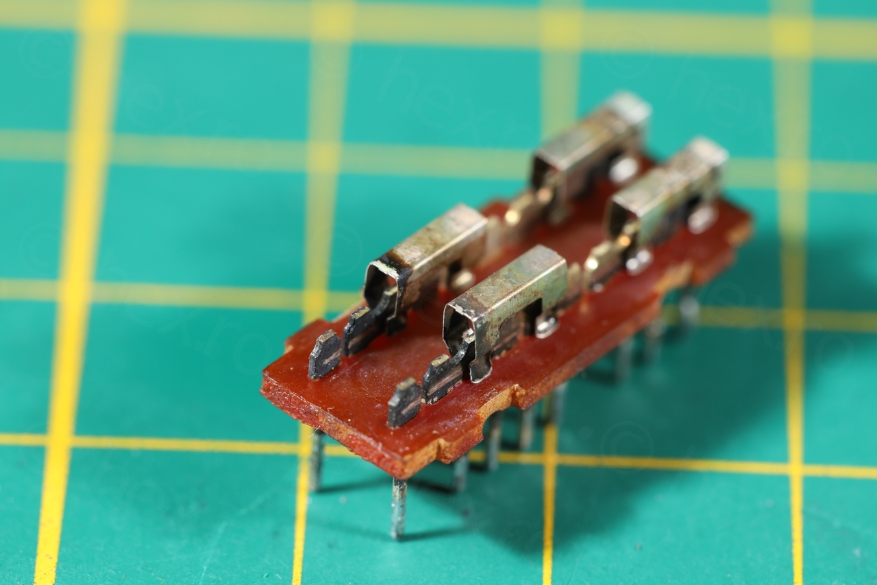
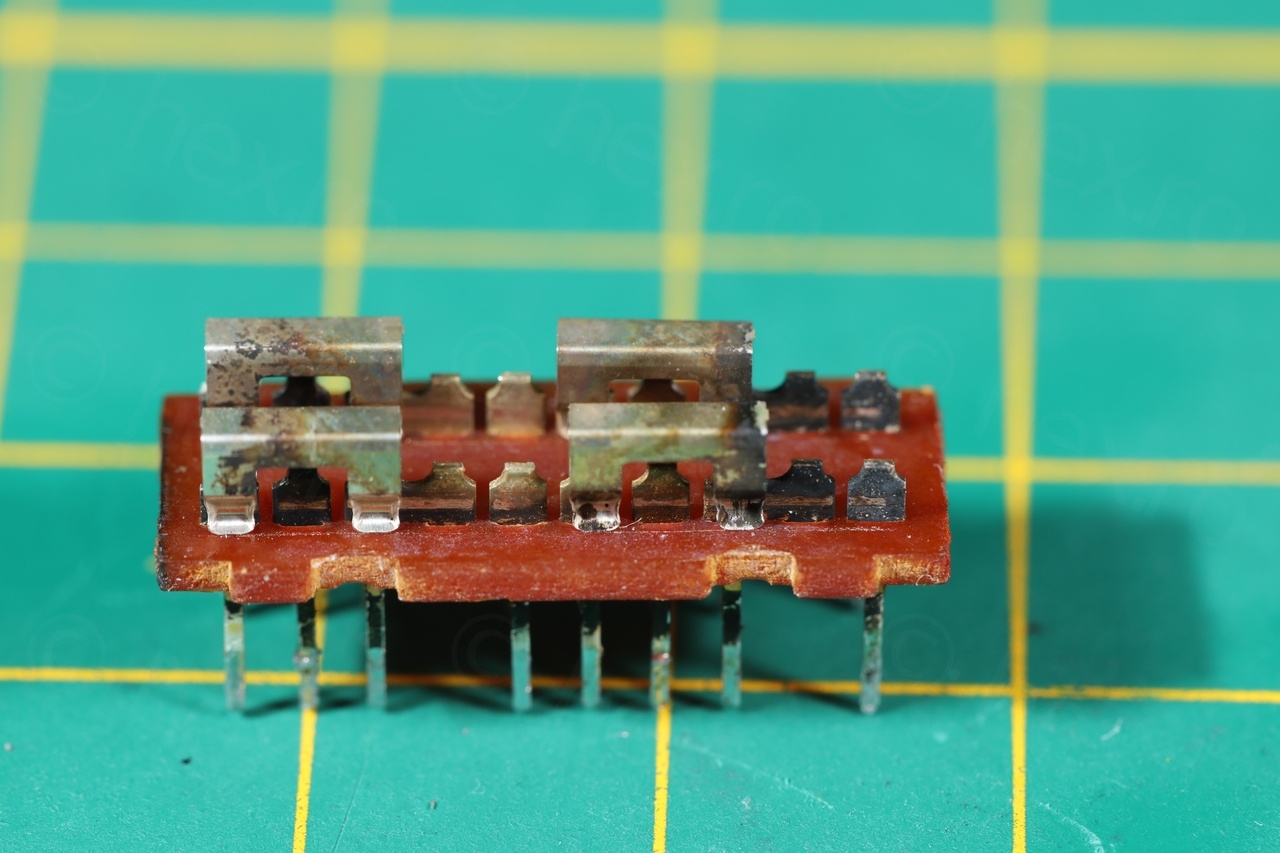
I realized I have no chance of cleaning the little sliders above without destroying them. Figured I’d to just soak them in contact cleaner while I used a lot of cotton buds to clean the pins themselves. Stayed away from cheating with low grit sand paper. It is always easier to destroy than to rebuild..
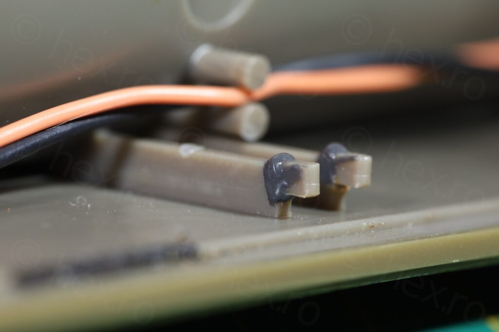
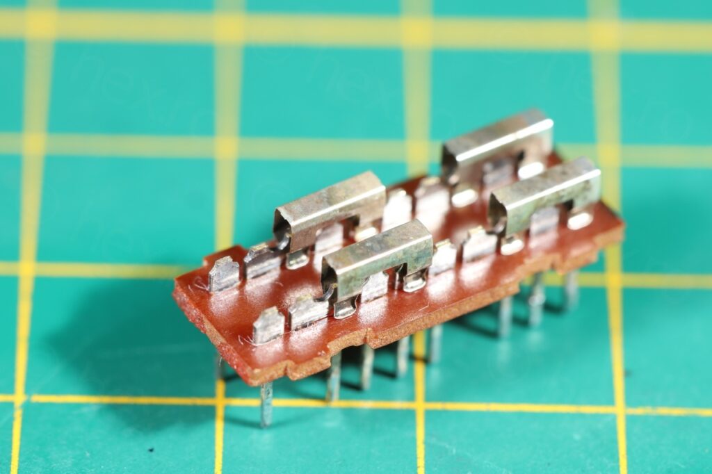
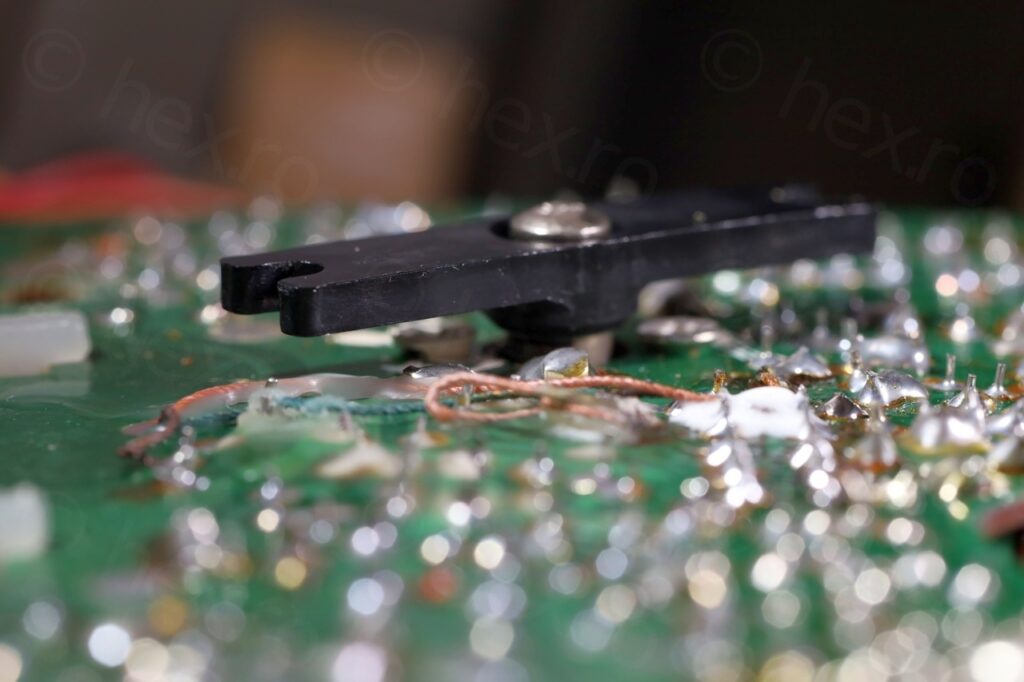
After few cotton buds and a lot of contact cleaner later:
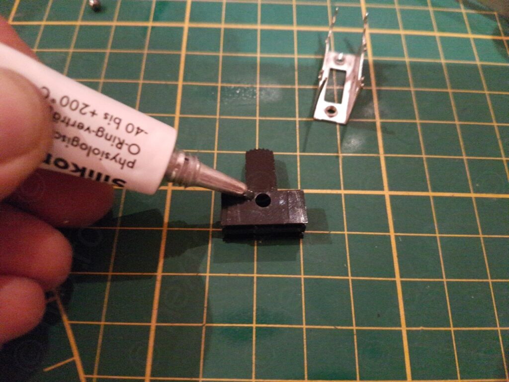
Of course, I had to grease the button too before reassembling everything back.
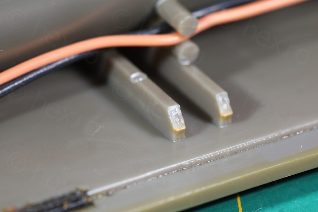
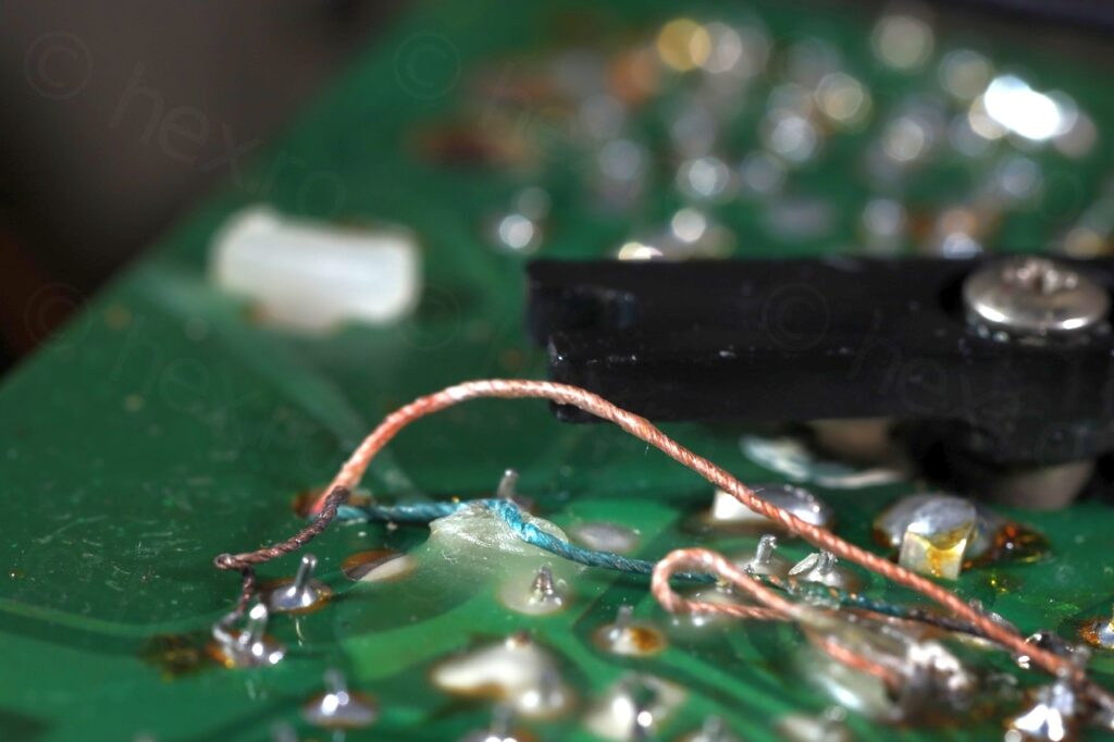
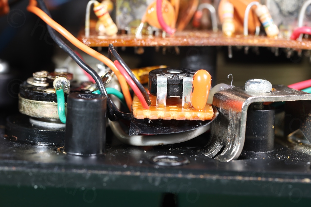
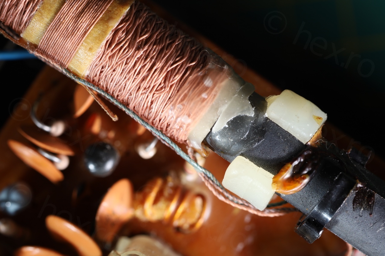
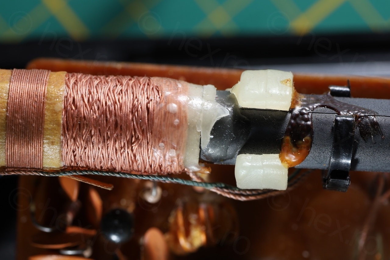
When soldering back the band switch, the MW/LW antenna wires had to also be solderered. Since the original wax melted when taking the switch out, I had to use some paraffin wax to hold the wires down, otherwise they would have gotten in the way of the tuning capacitor:
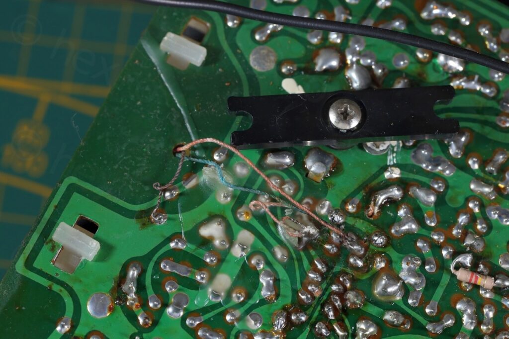
Finally, the MW / LW reception was back 🙂 and loud. Same volume as FM.
Volume too loud with volume pot to the minimum
This puzzled me a lot. All transistor voltages were right (0.1V off from the schematics maximum). A dead capacitor would most definitively lower the volume or introduce distortions, but here the volume was very loud!
I found an interesting discussion here – where people restoring old radios do sometimes have this problem and the idea is that producers used the cheapest possible volume pots, and instead of the pot having 0Ω at minimum, they had a much higher resistance. Decided to measure:
Volume pot measured about 100Ω when OFF, 1.5kΩ when ON (and set to minimum) and about 27kΩ when at maximum. The schematic calls for a 20kΩ potentiometer.
I was almost ready to take apart the pot and see if I can rotate the wiper so that it reads less when at minimum. I gave up after checking some videos online – the wiper looked press fit to the shaft – impossible to rotate it. Ordering a similar looking pot is difficult (they seem very expensive) or the cheap ones have different shafts, so next step was what can I do to lower the volume ?
There were few choices: rebias the transistors or use an additional voltage divider after the pot. Rebiasing the transistors would be hard – a mix of Silicon and Germanium final stage with a little feedback loop and a thermistor in between – that would need a lot of simulations. The voltage divider with its own bypass cap may also have unwanted effects.
By now, I have accepted I will never be able to get the pot to read 0Ω at minimum, and that I would have to rebuild the amplifier stage in a simulator. A few hours later:
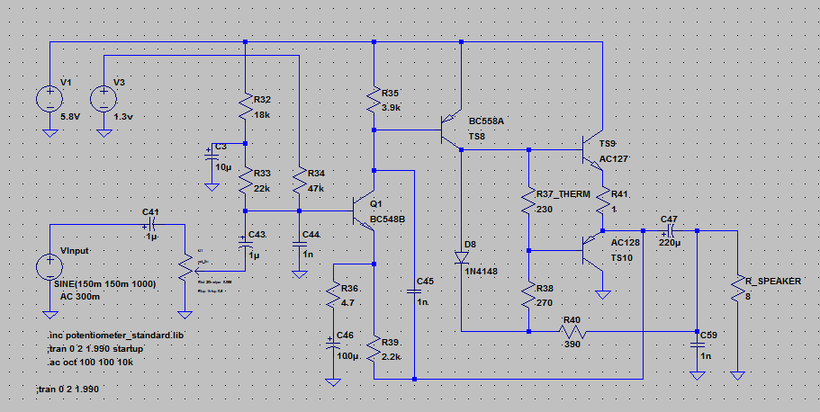
This proved challenging because the R39 2.2kΩ is poorly drawn in the Philips 380 schematic and I thought it was a 22kΩ resistor. Only after cross checking with the Philips 270 schematic I realized the mistake, there, it is properly scanned and it shows it is 2.2kΩ in fact. Then amplifier started working correctly 🙂 in the simulator!
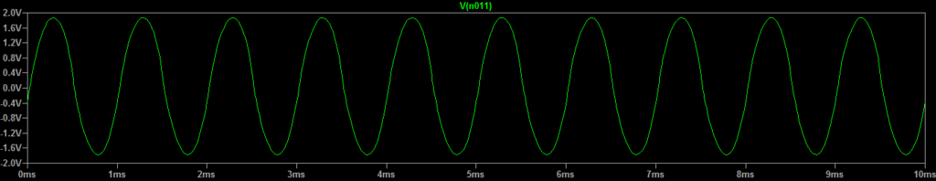
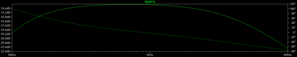
Having the amplifier in a simulator was extremely revealing. With the volume potentiometer set at minimum real life, 1.5kΩ, the voltage over the speaker was already 4Vpp (out of the 5.8V power supply):
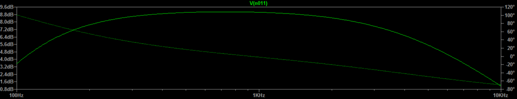
It seems that the 3db point is at 4.2kHz – I measured so that I make sure that whatever changes I do, at least they won’t decrease the existing “performance” of the radio:
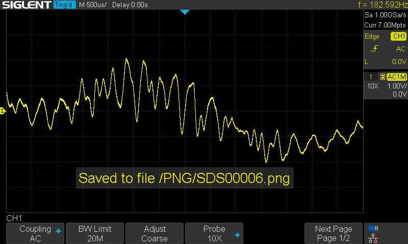
Trying to confirm the simulation results, I probed the waveform of the loudspeaker itself and indeed, it was also 4Vpp:
Confirming that the schematic works , I decided to try out various ways to attenuate the signal after the volume potentiometer and settled up with this schematic using a 1μF Tantalum bypass capacitor and a 47kΩ potentiometer as the divider itself:
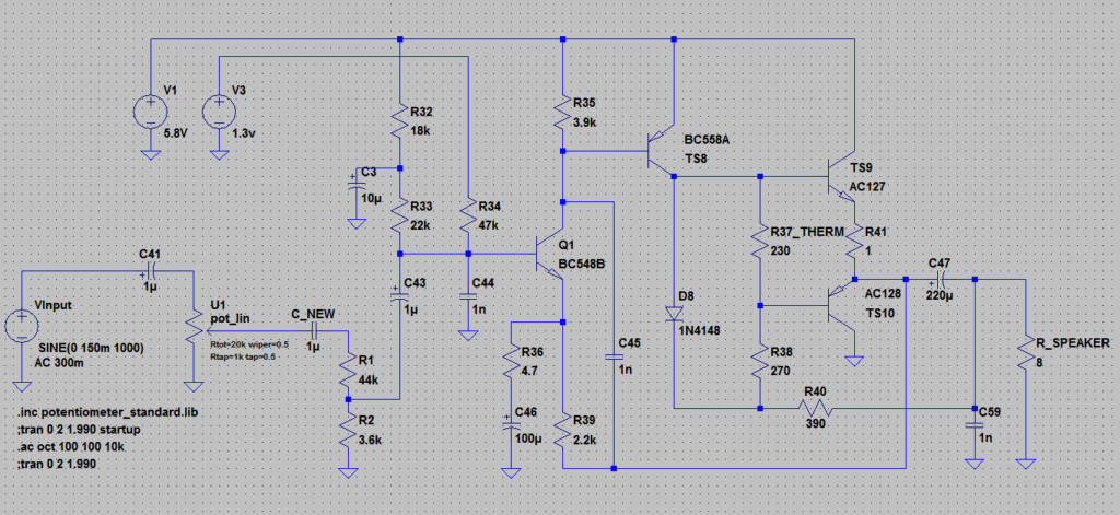
This felt the least invasive approach. No changes to the schematic itself, only one wire to desolder from the original potentiometer and without having to open it. I tuned the additional divider so that with the volume potentiometer set to minimum, the output voltage would be 250mVpp – much quieter. The volume pot would have to be at 20kΩ to get the 4Vpp. Thus, a 1:10 attenuation provided the best of the two worlds.
Results of the simulation below:

Finally, I decided to put everything together:
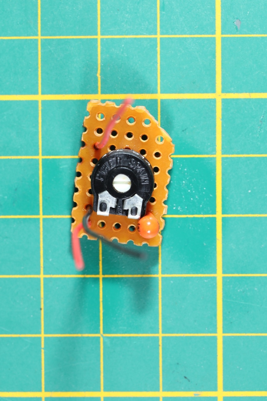
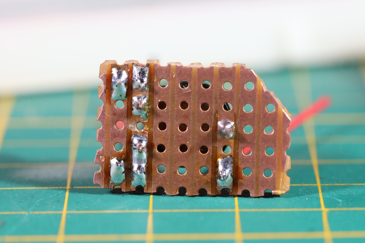

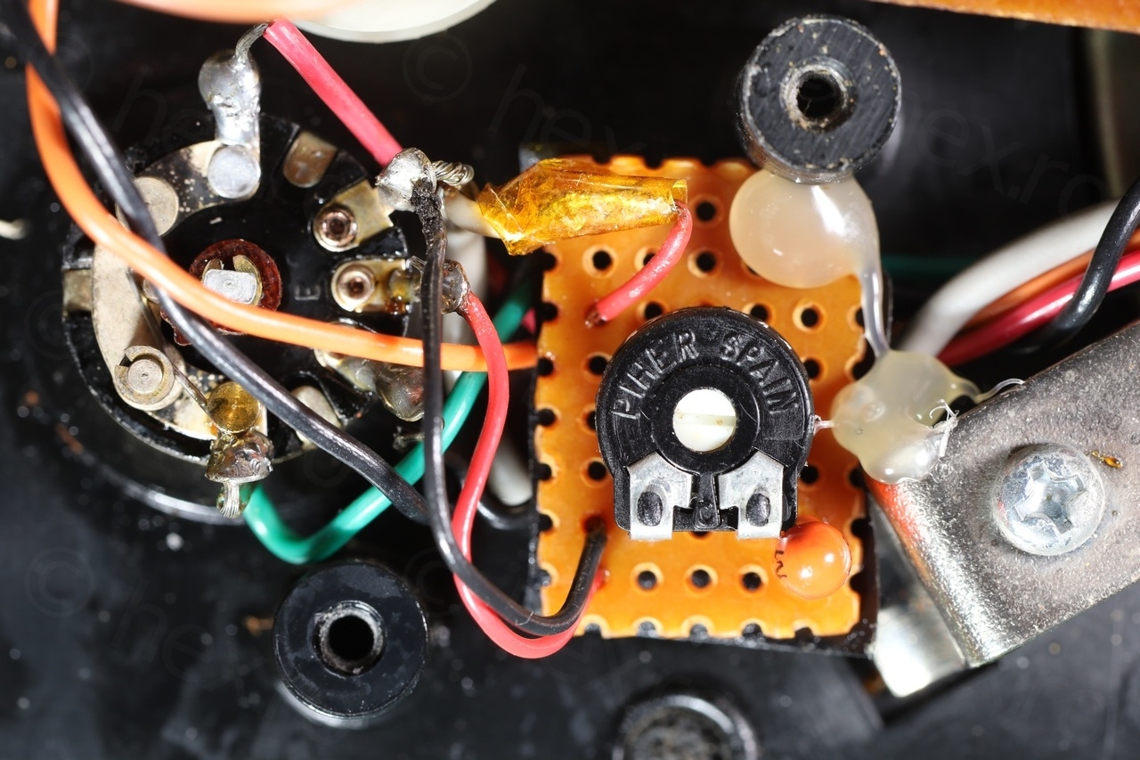

I used a small protoboard to reduce the possible interference pick up, managed to find a place to keep it close to the original volume potentiometer and not get in the way of the battery compartment. I put a small electrical tape underneath (so that it doesn’t destroy the wires that are passing under) and fixed it in place with hot glue.
Results:
The camera decided to compensate the sound level and radio still sounds loud. Is not. Volume now is low when turned on.
Cleaning up
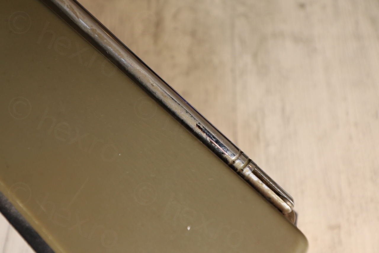
It took some a lot of rubbing to clean the radio properly of the hardened thin grease / deposits and the dust.
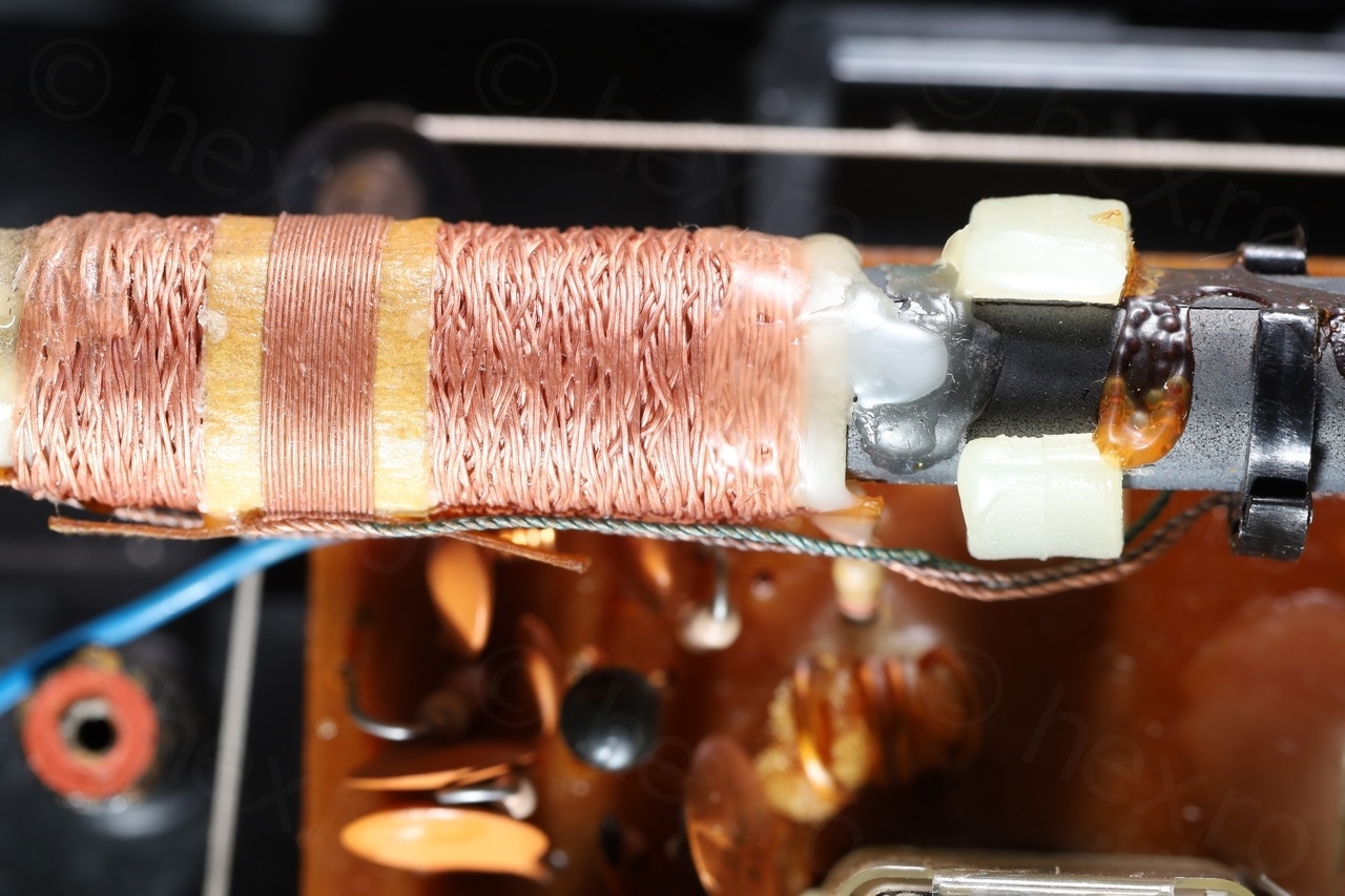
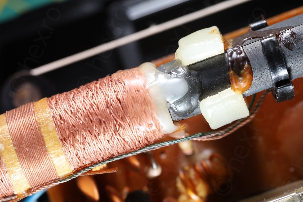
When opening the radio, I also found the coil windings of the AM antenna was also not held down by the initial wax, it had cracked. I had to use a paraffin wax bud and melt it down with the hot air gun to secure it back in place:
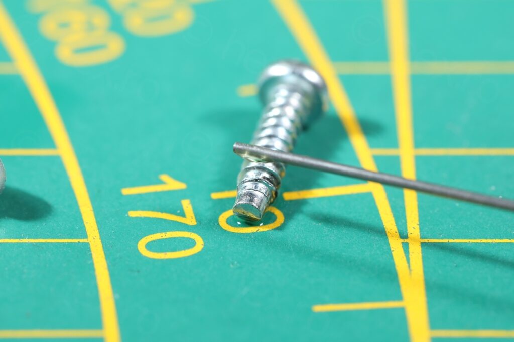
Add a dab of sewing machine oil or silicone grease on the screws before tightening them down is a good thing, less friction on the plastic so longer duration:
Conclusion
I think this Radio never worked properly and was always too loud. The switch has a soft spot in the middle (MW) which indicates it was still usable since if the AM stations were far …
Erhard Fischer
Ein gutes Gerät!-habe günstig den “kleinen Bruder”(270) erworben,mit UKW/MW.
die “Schwachstellen” des Gerätes waren definitiv immer der Wellenbereichsschalter.bei meinem Gerät waren auch noch die Batteriekontakt “komplett verrostet/Weggegammelt.da habe ich zum Glück ein ähnliches Philips-Geraet zum Ausschlachten da gehabt&gerne geopfert.Ein weiterer Schwachpunkt war immer die dünne,empfindliche Teleskopantenne,die man auch nur nach rechts und links schwenken konnte(nicht drehbar)
Dennoch ein leistungsfähiges Kofferradio,was es wert ist,zu restaurieren!-die “Freude danach” ist einfach großartig.Mein Motto:”die Alten Halten”!
Hugo Carmo
Hi.
Great restoration!
I have an Model 270 wich I would like to restore to.
The only problem is that the power transformer ir burned out and I can´t find the right model for replace.
Do You know wich model is? In the service manual it only refers to S16!
Thank You,
Best Regards,
Hugo
viulian
Hello,
I don’t have the model either..
I could deduct that it has to be able to offer 6V. Since the fuse is rated for 250mA, then the transformer should handle at least that in the secondary.
Not sure I read your message right. As to me it sounds that you want the exact model, but what to do with it – I doubt you can find it for sale. In this scenario, it probably would be worthy to wait for a donor radio announcement on the second hand shops around you ?