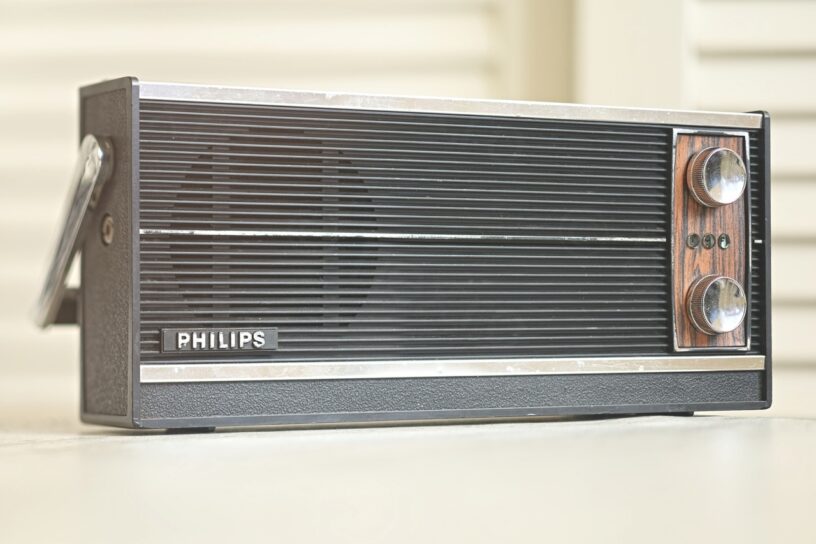


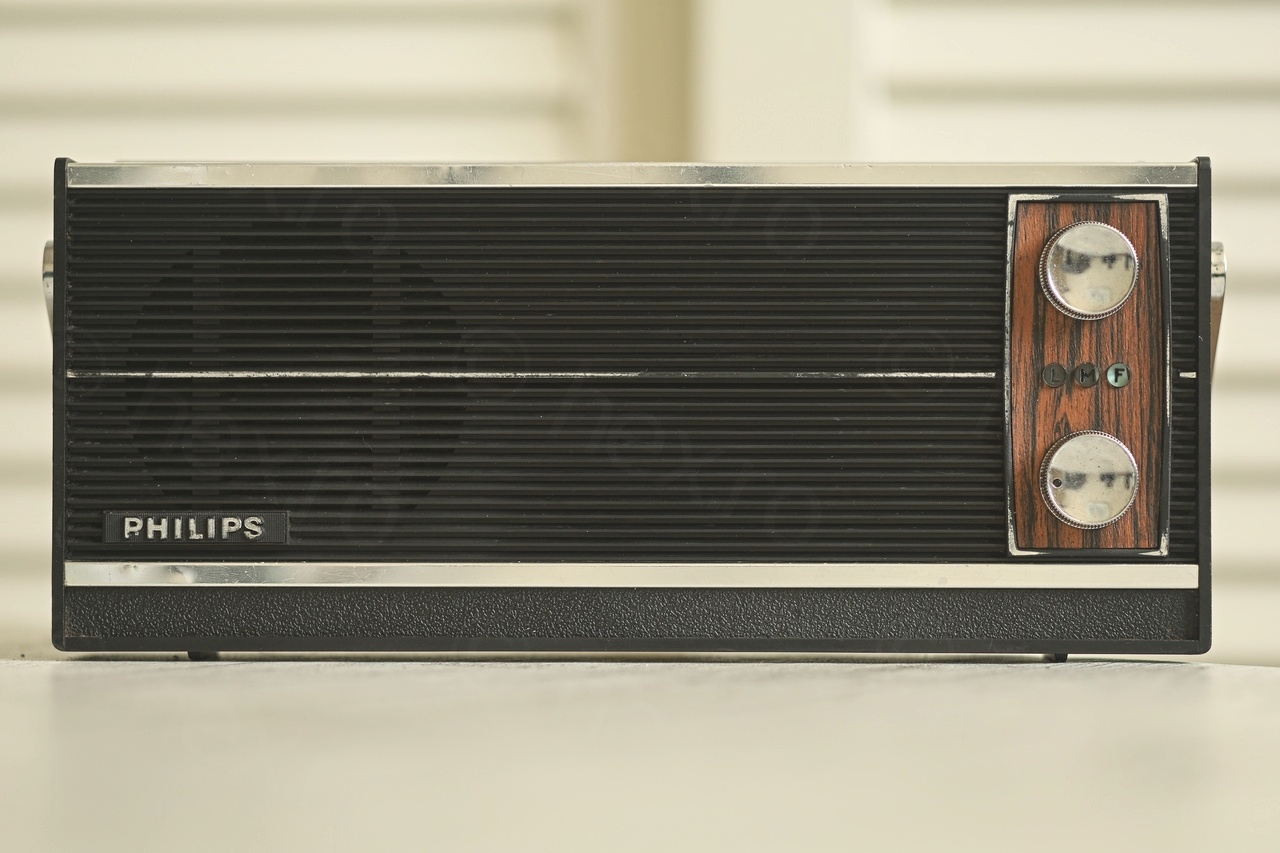
Found this radio at a local brocante (flea market).
It was so dirty I had seconds thoughts whether I should be buying it or not … It had that old radio look though and as there is an negotiation advantage if radio looks poorly so I looked more carefully. It seemed to have all parts, the tuning button was working (although I almost couldn’t see the dial due to grime), battery holder was intact, antenna was intact too. I bought it.
Table of Contents
- Evaluation
- Opening up the radio
- Fixing FM reception
- Cracked Volume Button
- Cracked Dial Scale
- Rebuilding the Volume Potentiometer
- Re-gluing lifted traces
- Recapping it ?
- Realigning the FM dial scale
- Replacing crumbling foam
- Cleaning Corrosion / Rust
- Gluing the anti-dust filter / fabric on the back case
- Putting it all back together
Evaluation
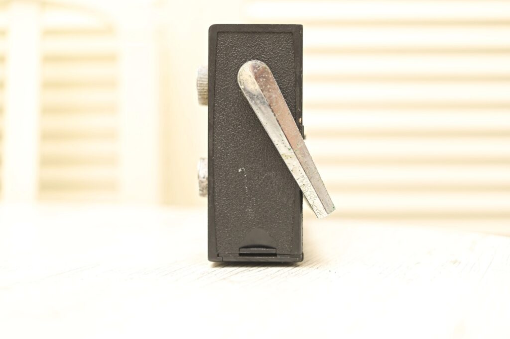
I quickly grabbed some mobile phone photos before bringing out the DSLR.
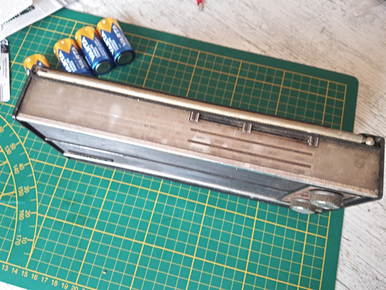

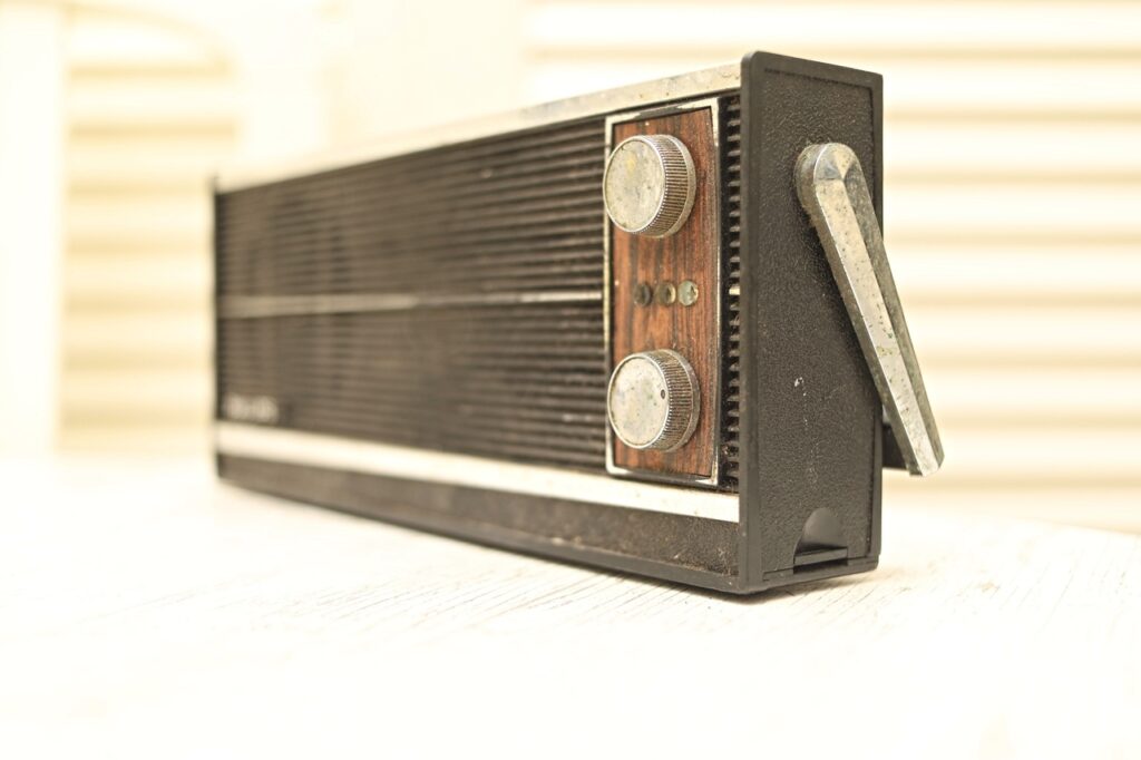
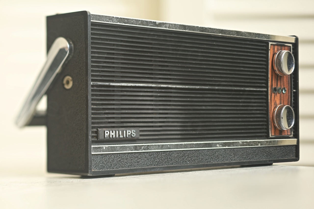
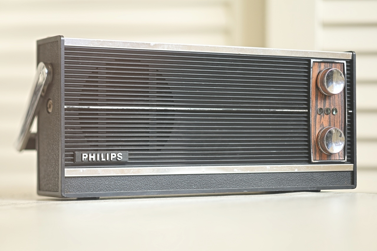
I took also some shots with the DSLR camera – since the mobile phone ones have the low resolution feel to them:


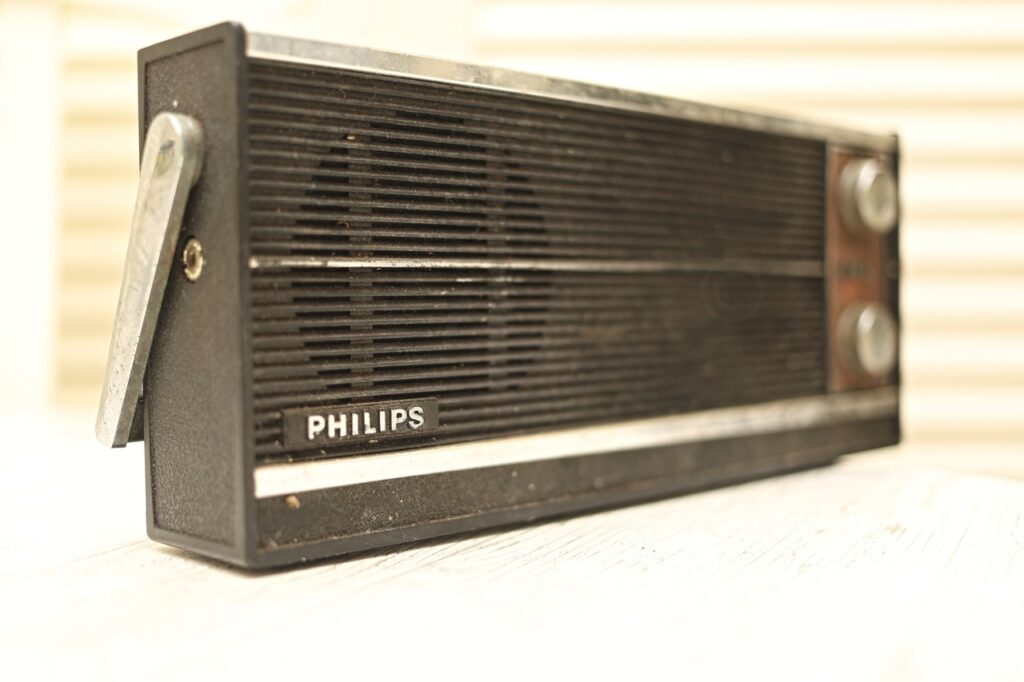
Also took some all around shots – but due to the intense light, the grime is not so obvious:
I bought some batteries and decided to try it – at first try there were loud cracks when operating the On/Off Volume button. No reception on FM too. However, just after I decided to record the initial tests video, the On/Off button stopped responding as you see below:
As a summary – it was tedious to restore. The local oscillator / mixer transistor had an internal short, the traces lifted very easily from the circuit board and had to fix few of them, the On/Off switch needed to be opened up and given a deep scrub, the volume button plastic shaft was snapped and needed gluing, a piece of foam inside was decomposing… etc. To add more insult to the injury, the schematic voltages are “Germanium” style, for example, schematic shows a voltage on a pin as being 1.33V, but the voltmeter will show 4.67V (6V-1.33V).
Opening up the radio
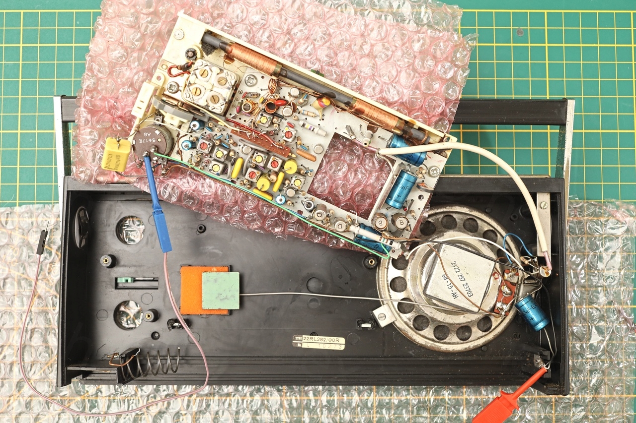
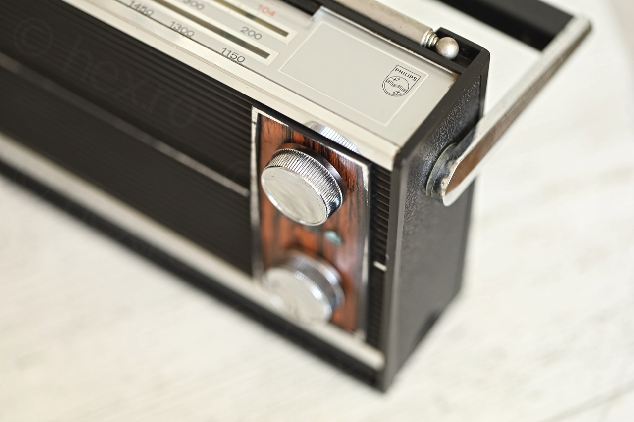
Opening up my Philips 22 RL 282 was easy, removal of the two screws inside the battery compartment, lift the case from the bottom (but not fully), then, once at an angle, slide out the back panel.
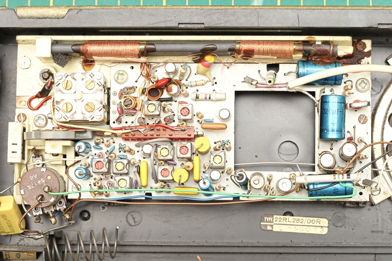
Surprisingly, the radio was clean inside:
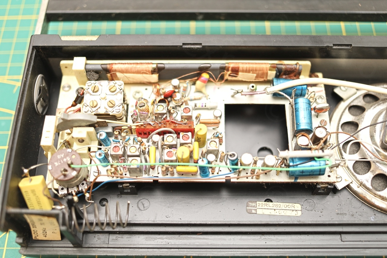
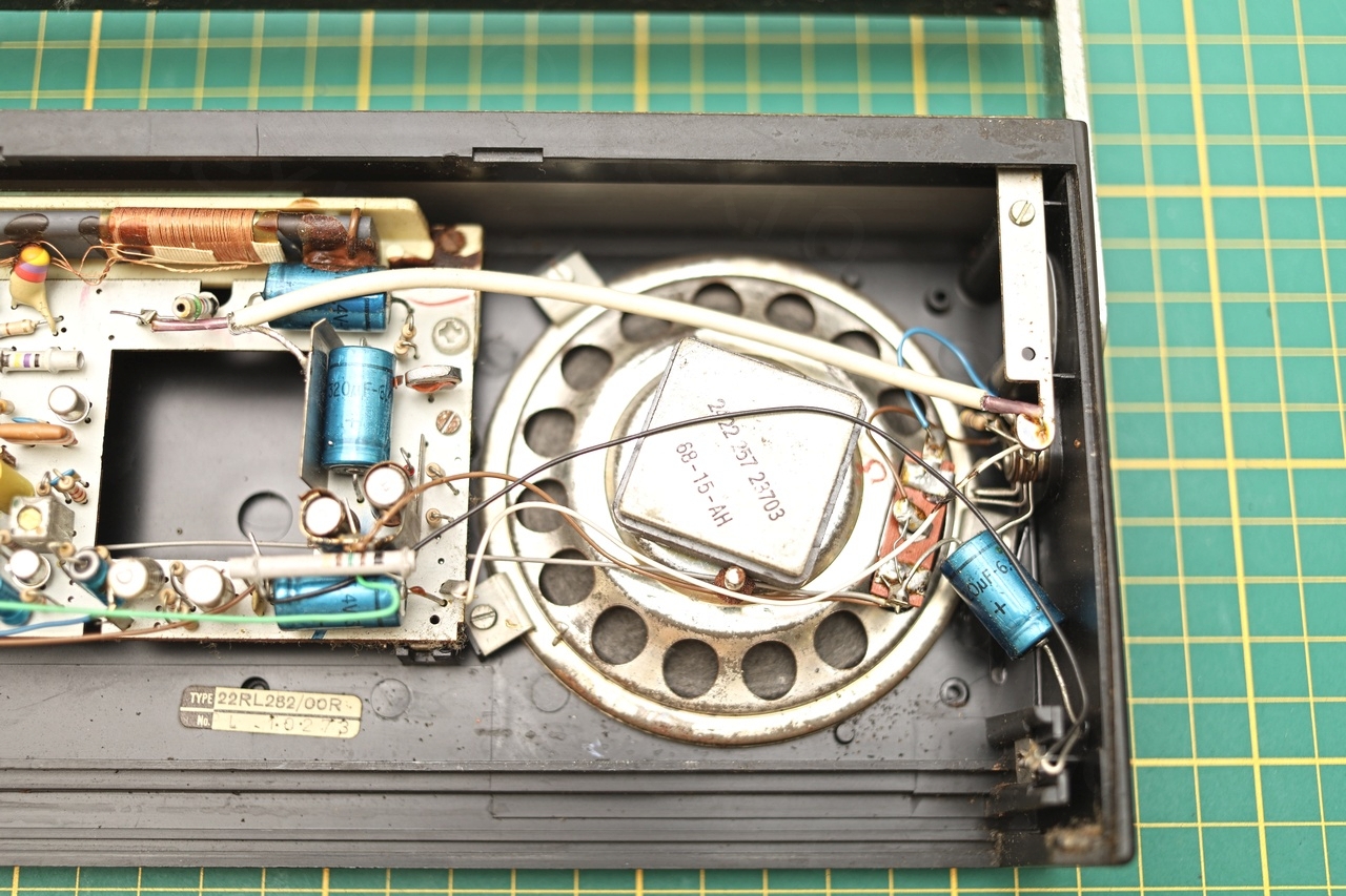

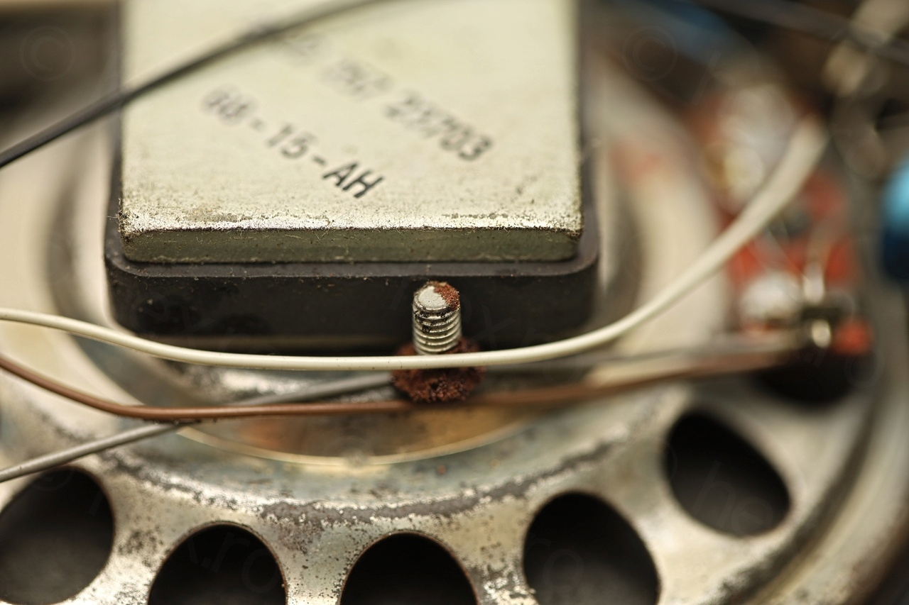

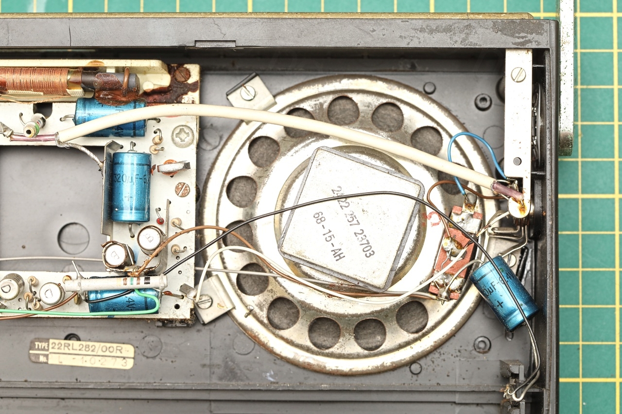

One screw was missing when trying to open the case – but TADAA, I found it attached to the speaker magnet!

Fixing FM reception
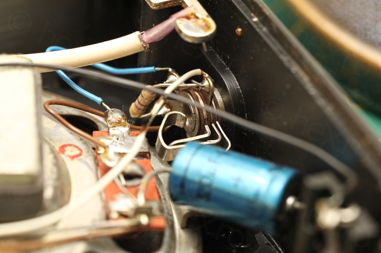
To take the board out and have access to the circuit board, the battery negative wire (going to the On/Off switch) has to be de-soldered first – this allows the circuit board to be flipped over.
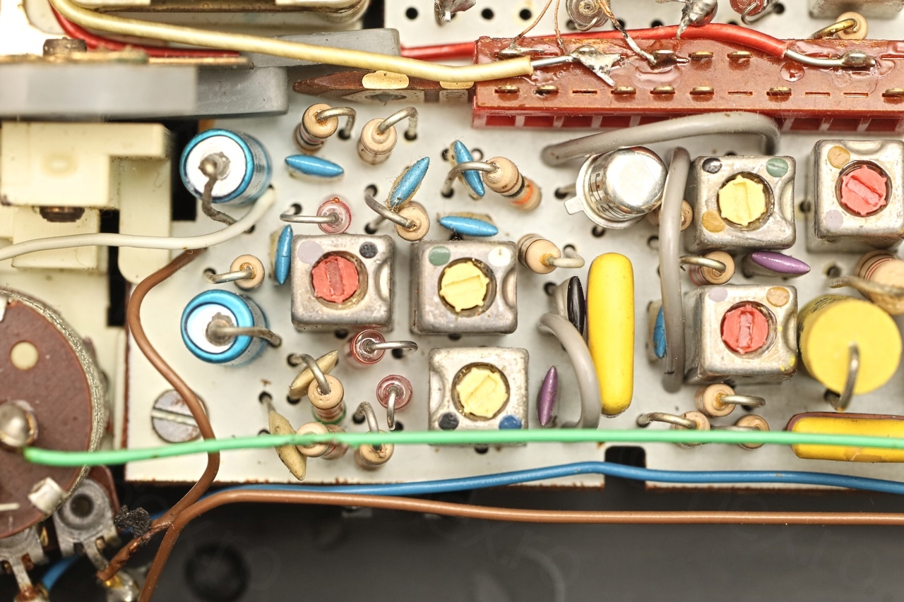
The radio was acting weird. Most of the times there was no FM reception, but sometimes, very rarely, there was some! There didn’t seem to be any cold solder connections though – so this puzzled me, as well as the 10.7MHz signal that would pass through without any problems.
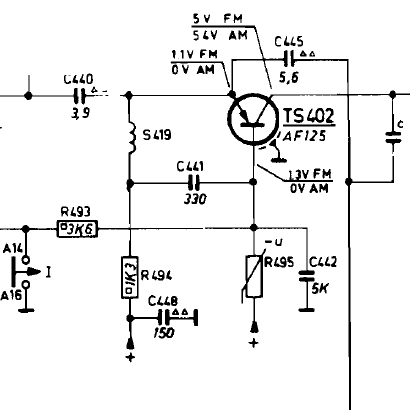
Since the service manual gave all values on the transistors pins – but the 6V- .. value, the “germanium” style, I decided to first measure all the voltages – and then subtract them from 6V, and then compare with the service manual. Wrote everything on a piece of paper (scanned below) and starting cross-checking …
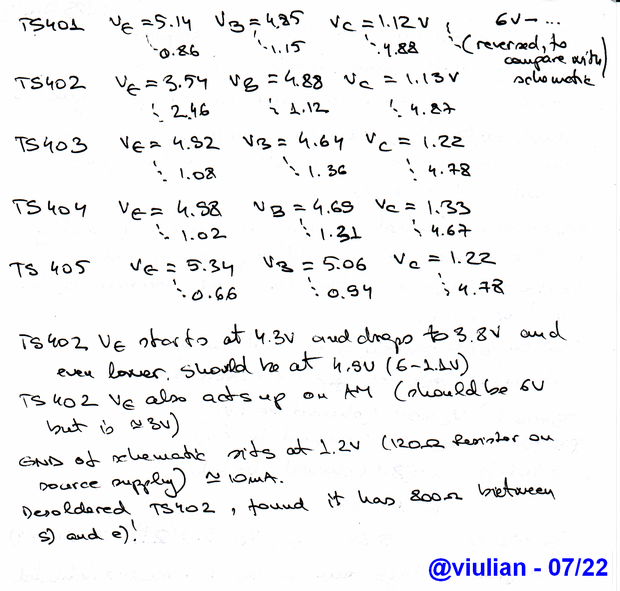
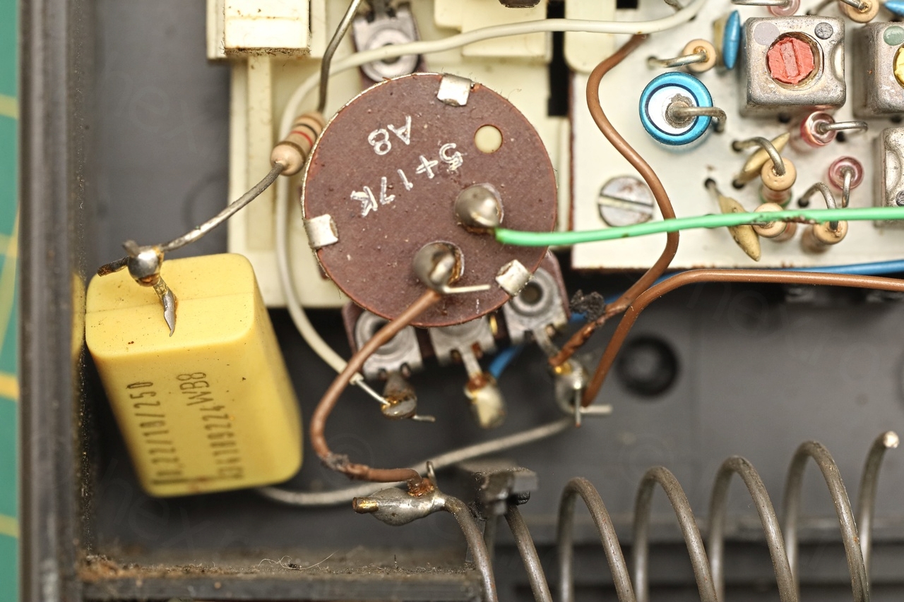
As you can see, there was a problem with the voltage on the Emitter of TS402. The voltage was too low … without any obvious consumers around ?! I mean all consuming paths were guarded by capacitors (ceramic so small changes of them being shorted) and even if S419 would have been shorted, there was still a 1K3 (R494) to +. So why would it drop so much voltage ?
I decided to pull it out to measure it first with the diode checker, and all seemed normal.
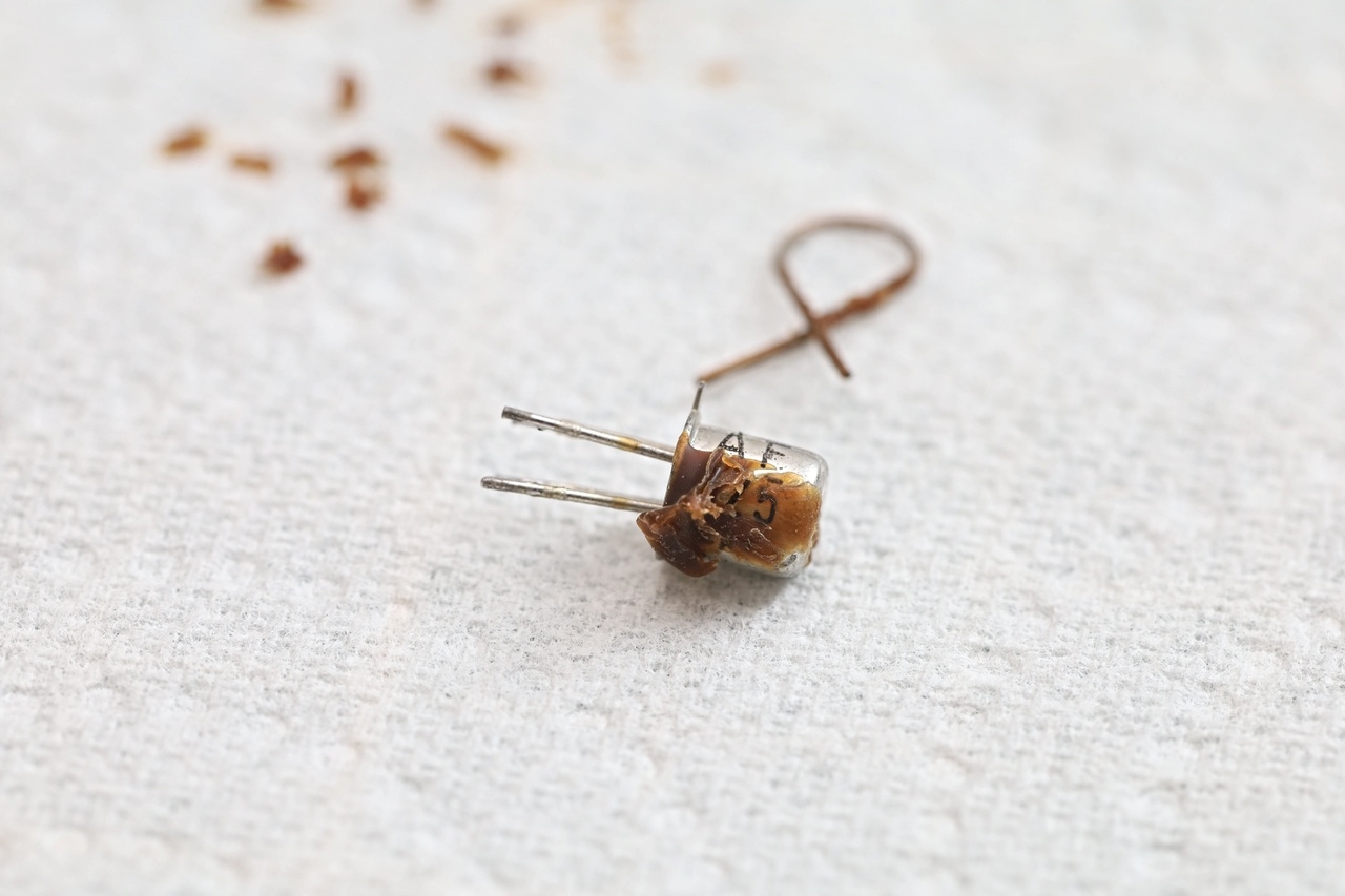
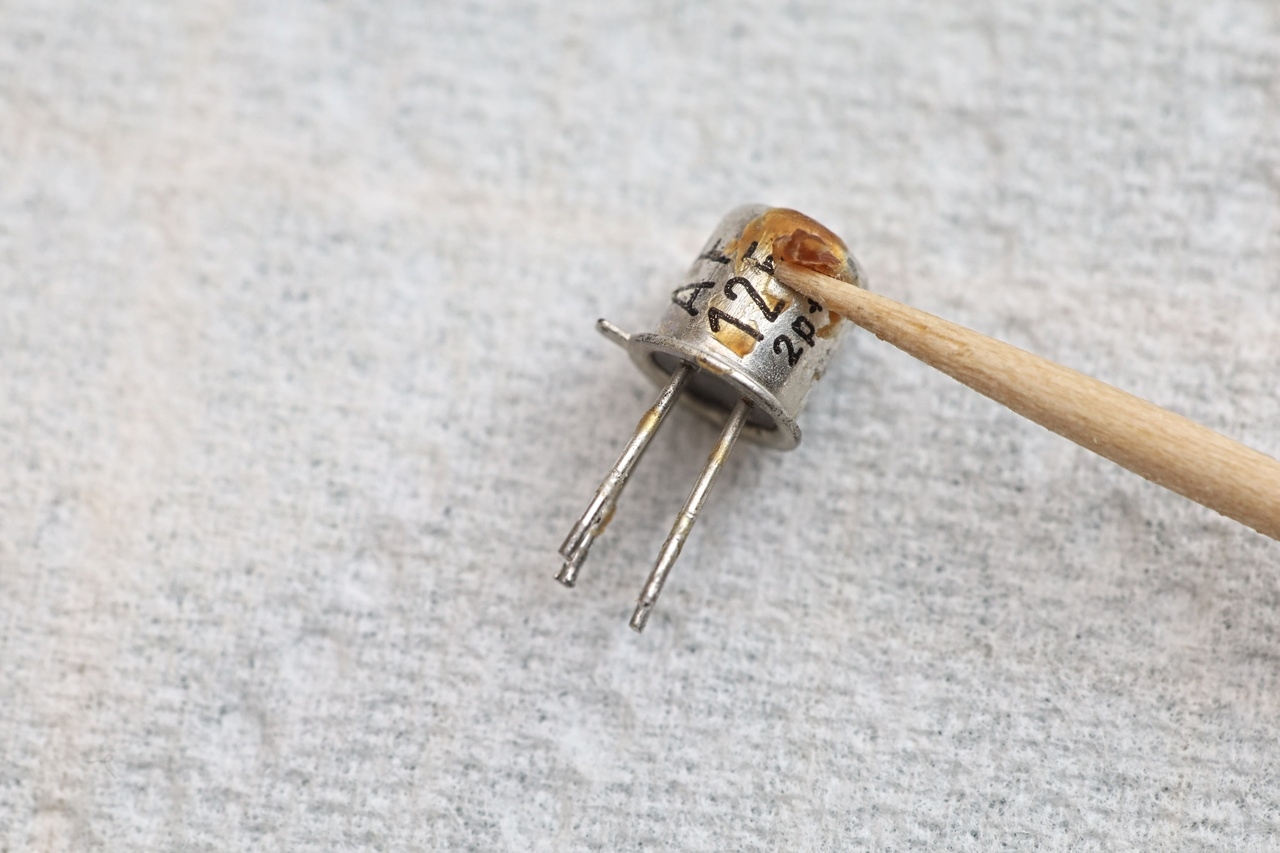

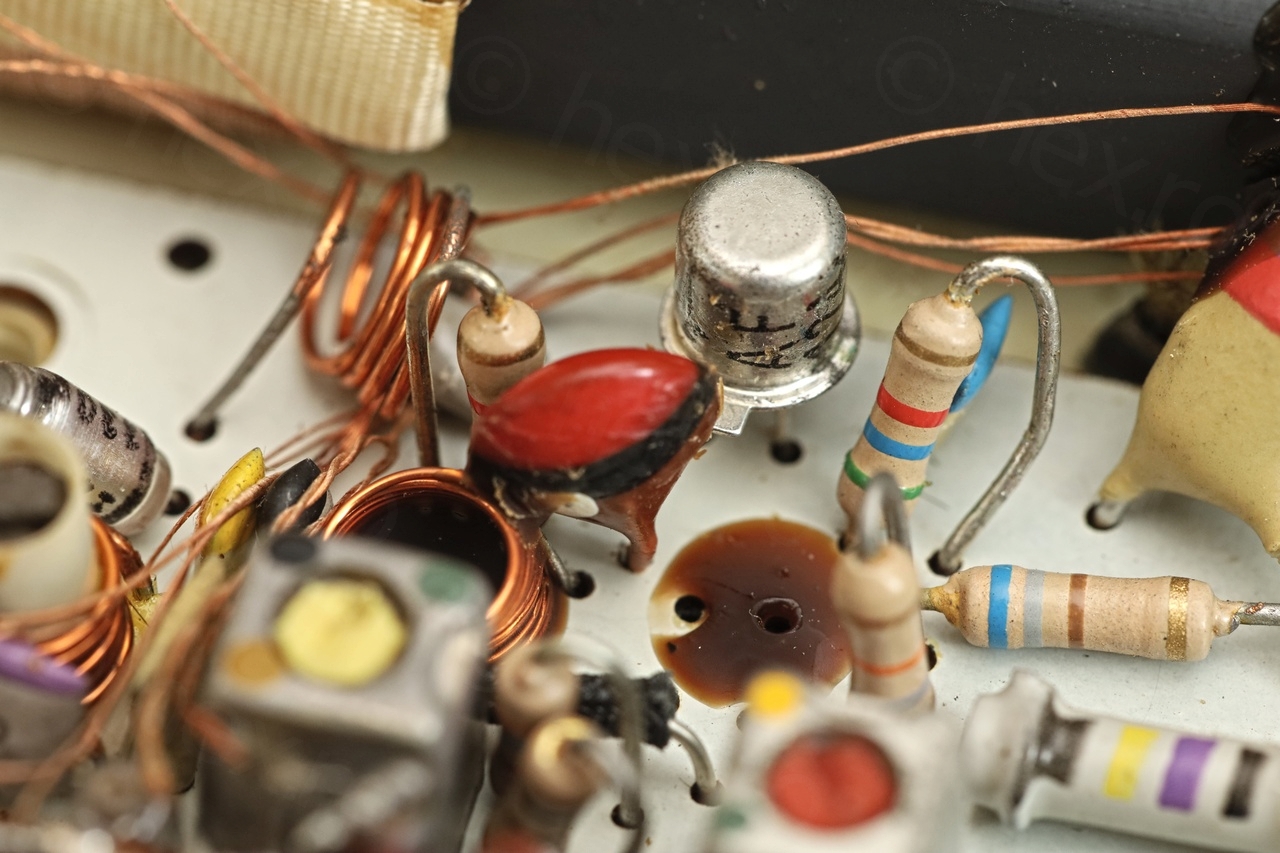
However, these transistors have a 4th pin, connected to the case – and in a stroke of luck, I decided to ohm it. And surprise! I found it to have 800 ohms to the Emitter. This was an internal low-ohmic path from Emitter to Ground (should have been an open circuit). When trying to position the transistor for a photo, I fiddled a bit too much with the Emitter pin which caused the Ohms reading to go higher, to > 15KΩ:
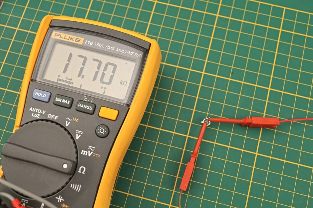
Resistance reading between the case pin of AF125 and its emitter
I was not able to get it to show the initial 800Ω resistance afterwards … but this was suspicious enough (suspect an internal transistor structure breakdown of some type) that I ordered some spares. Luckily still to be found on ebay:
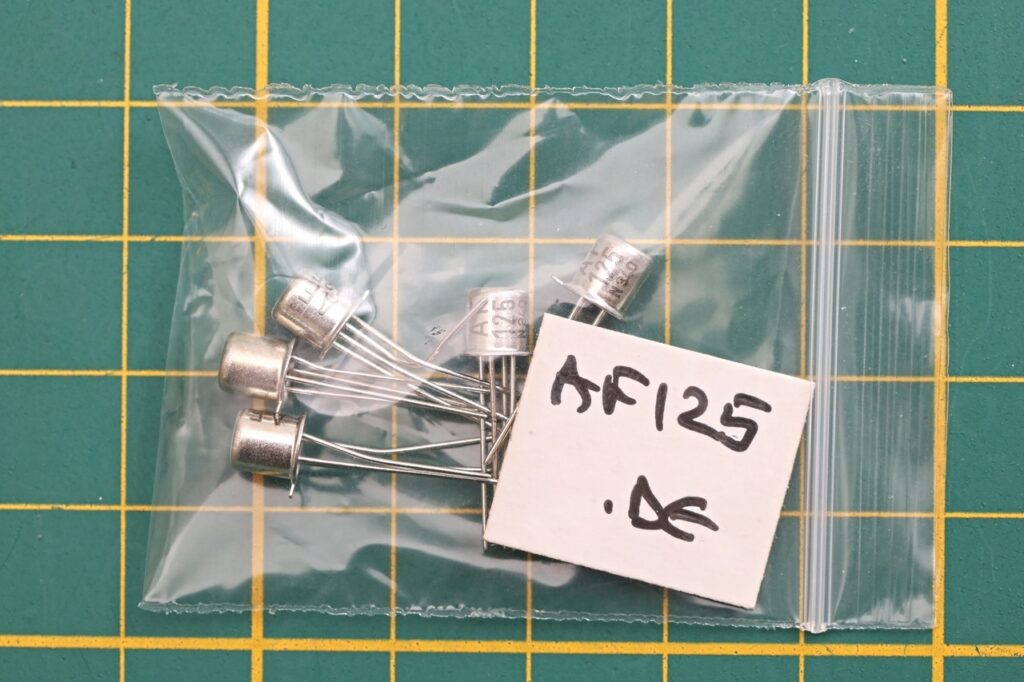
Of course, there’s an open (OL) between 4th pin and the Emitter on the new transistors .. once installed, I got the FM reception back 🙂 loud and clear. The TS402 is the local oscillator / mixer transistor for FM.
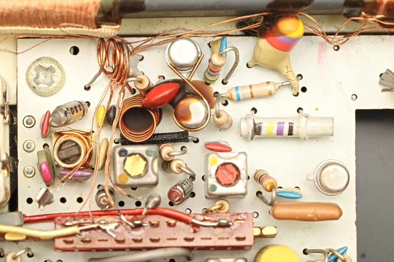
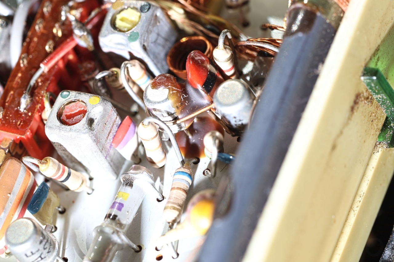
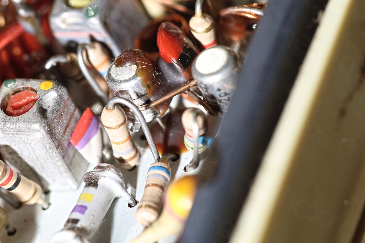
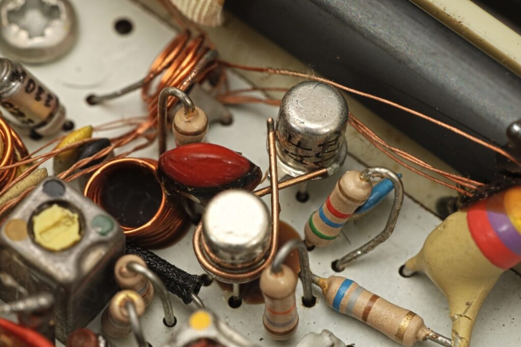
Removing the transistor first involved removal of the thick glue that was keeping it attached to the board and other components, as well as the mechanic coupler (thermal purposes I believe) that was attaching it to TS401 transistor (AF124):
Installing the replacement was easy, but a bit harder to reattach the metal connector:
After fixing the FM reception, I knew I can proceed with all the other things that were still wrong with the radio.
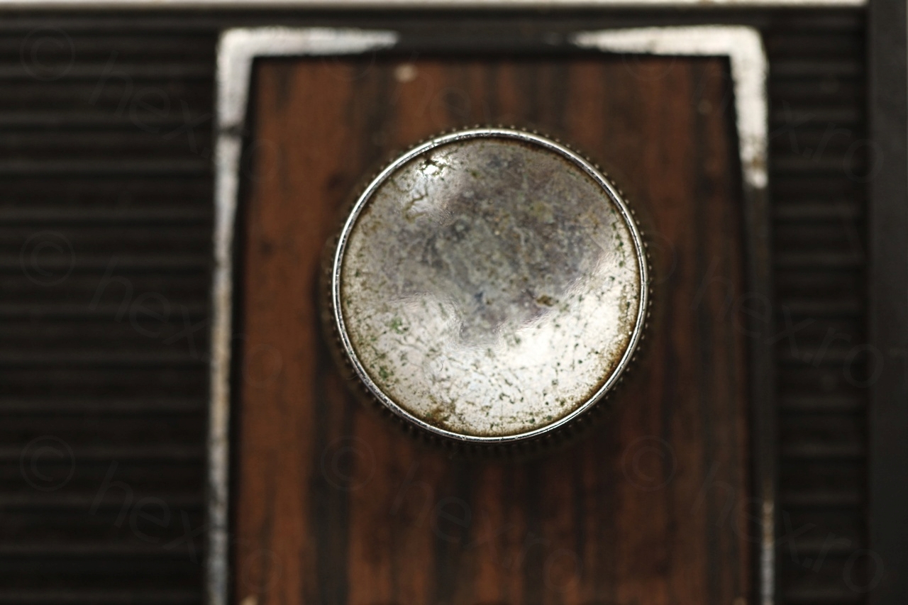
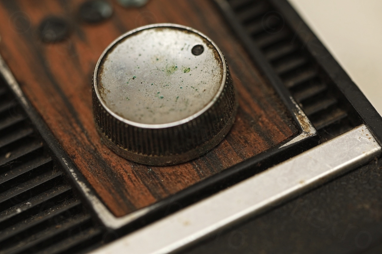
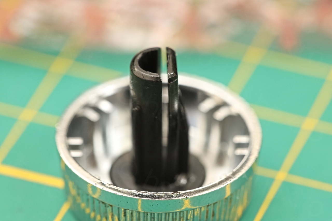
Cracked Volume Button
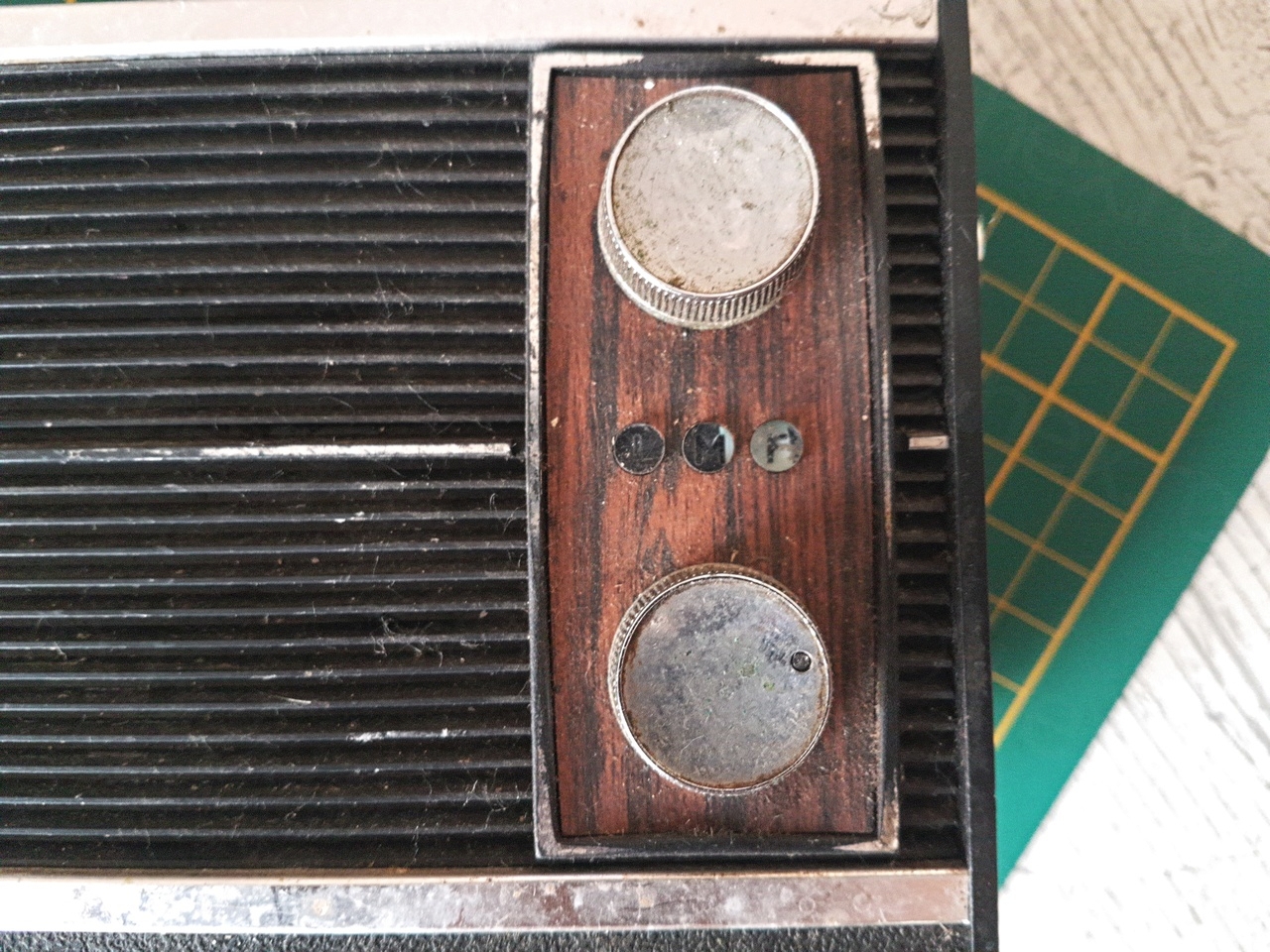
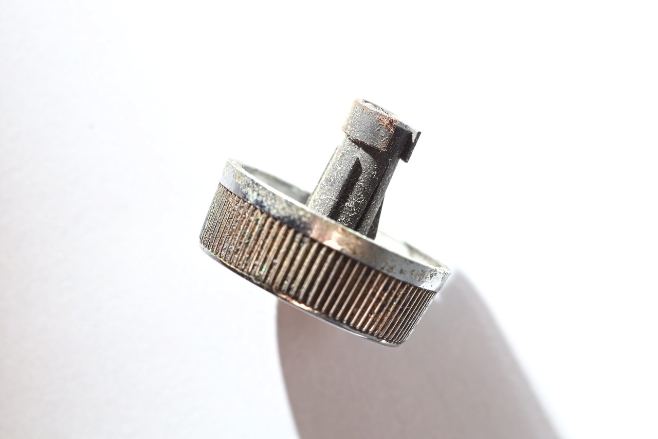
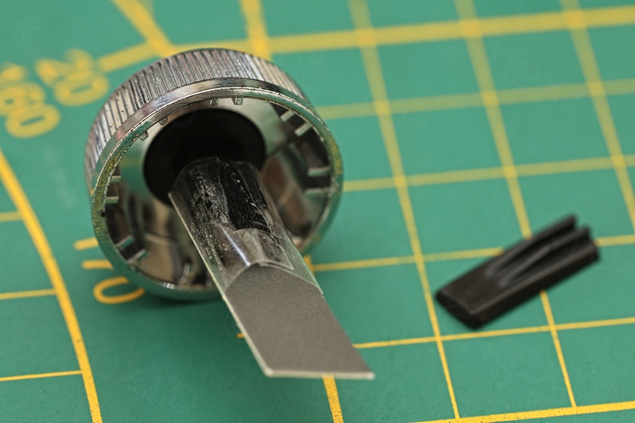
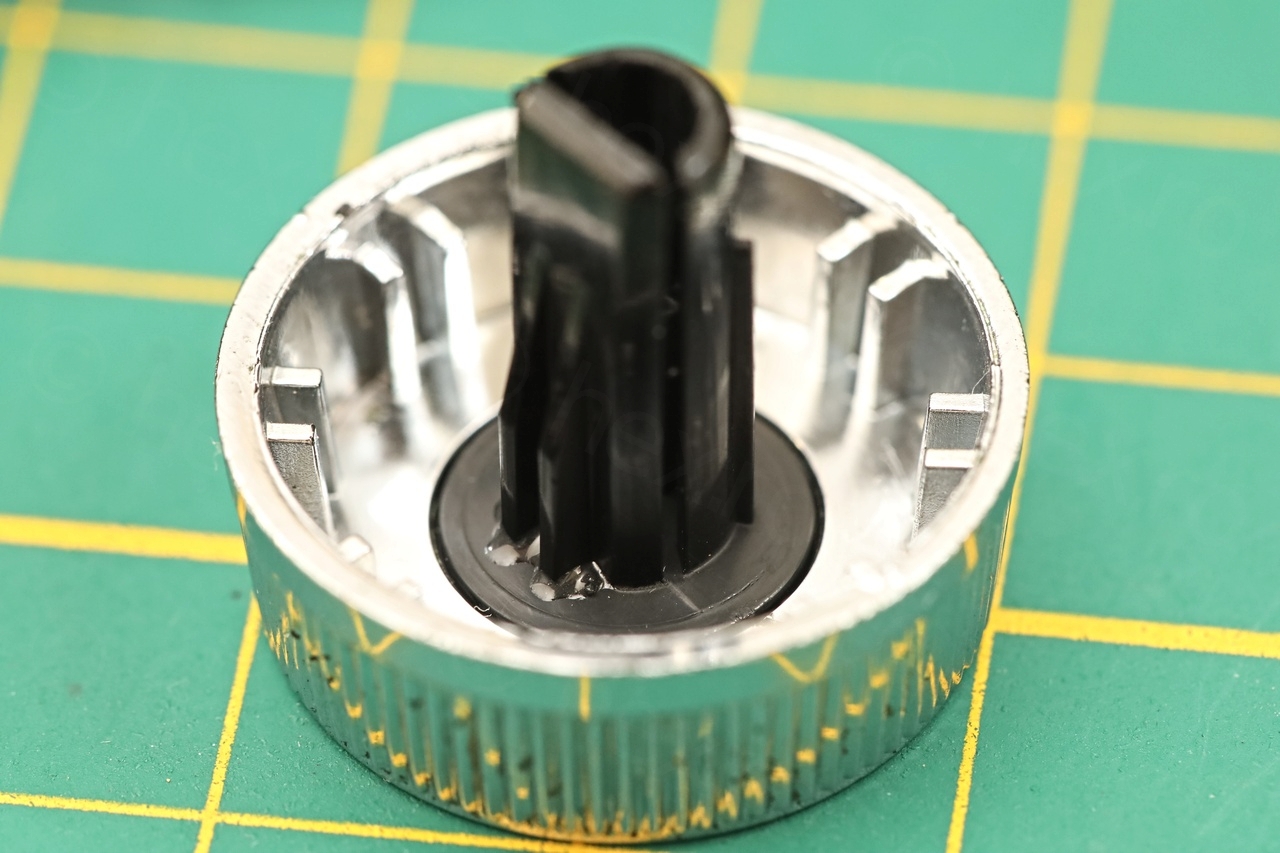
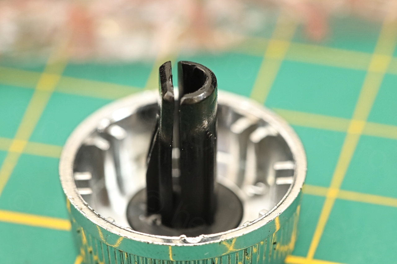
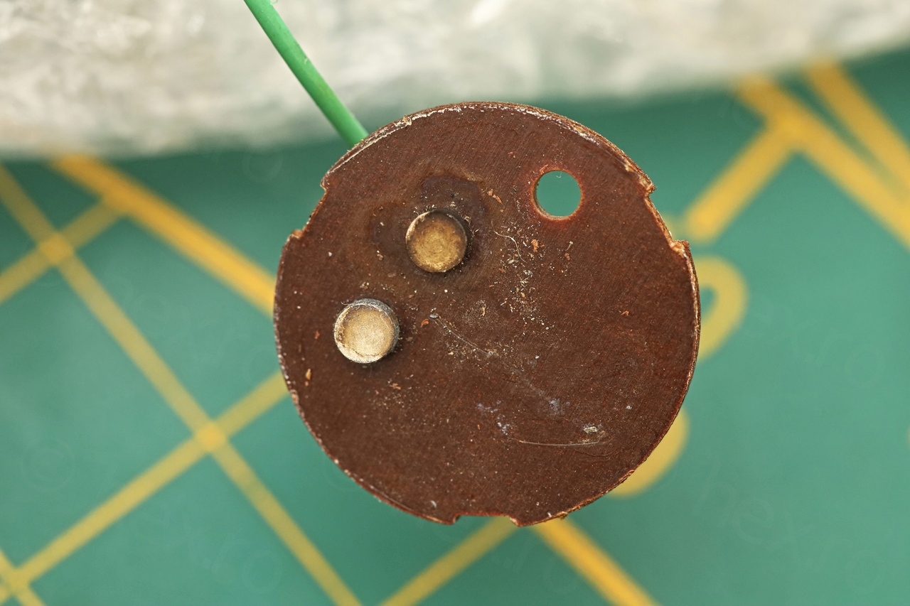
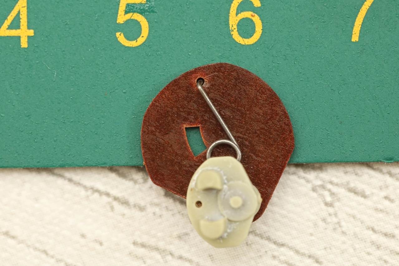
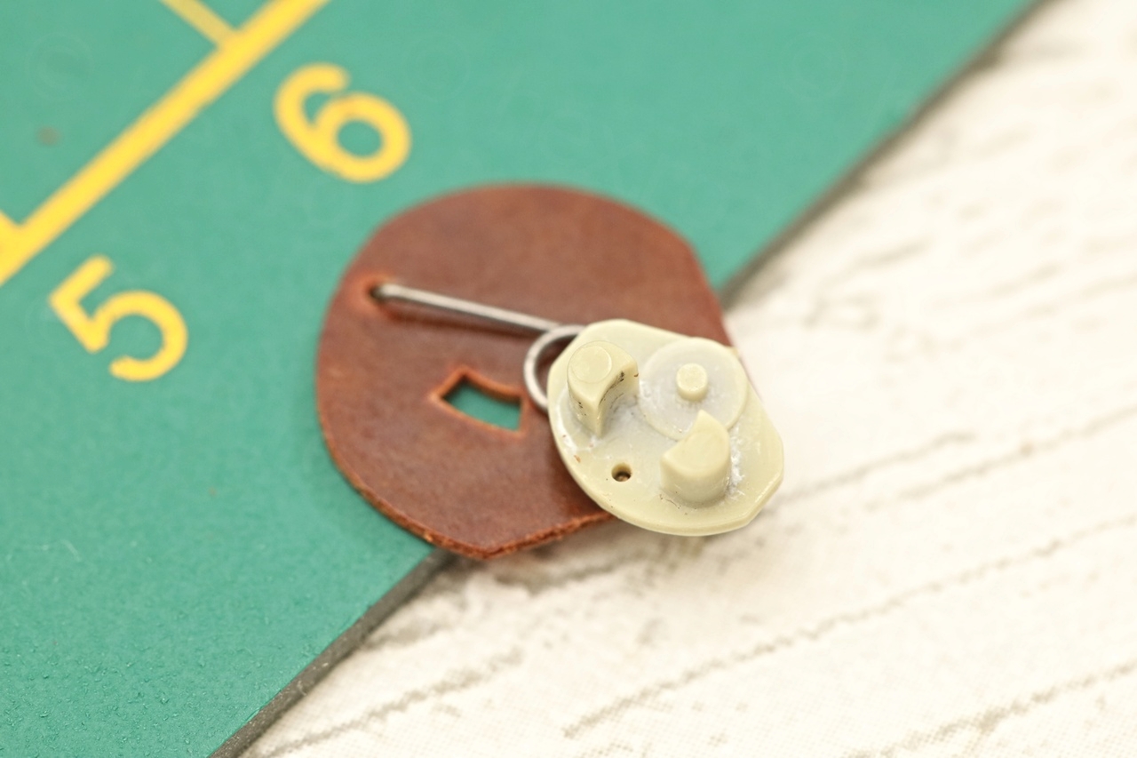
The Volume button was already cracked when I took it apart. Thankfully the designers of the Philips 22 RL 282 thought of the possibility and they already installed a metal clamp (to ensure that the button stays fixed to the shaft). Thus, I could recuperate the part:
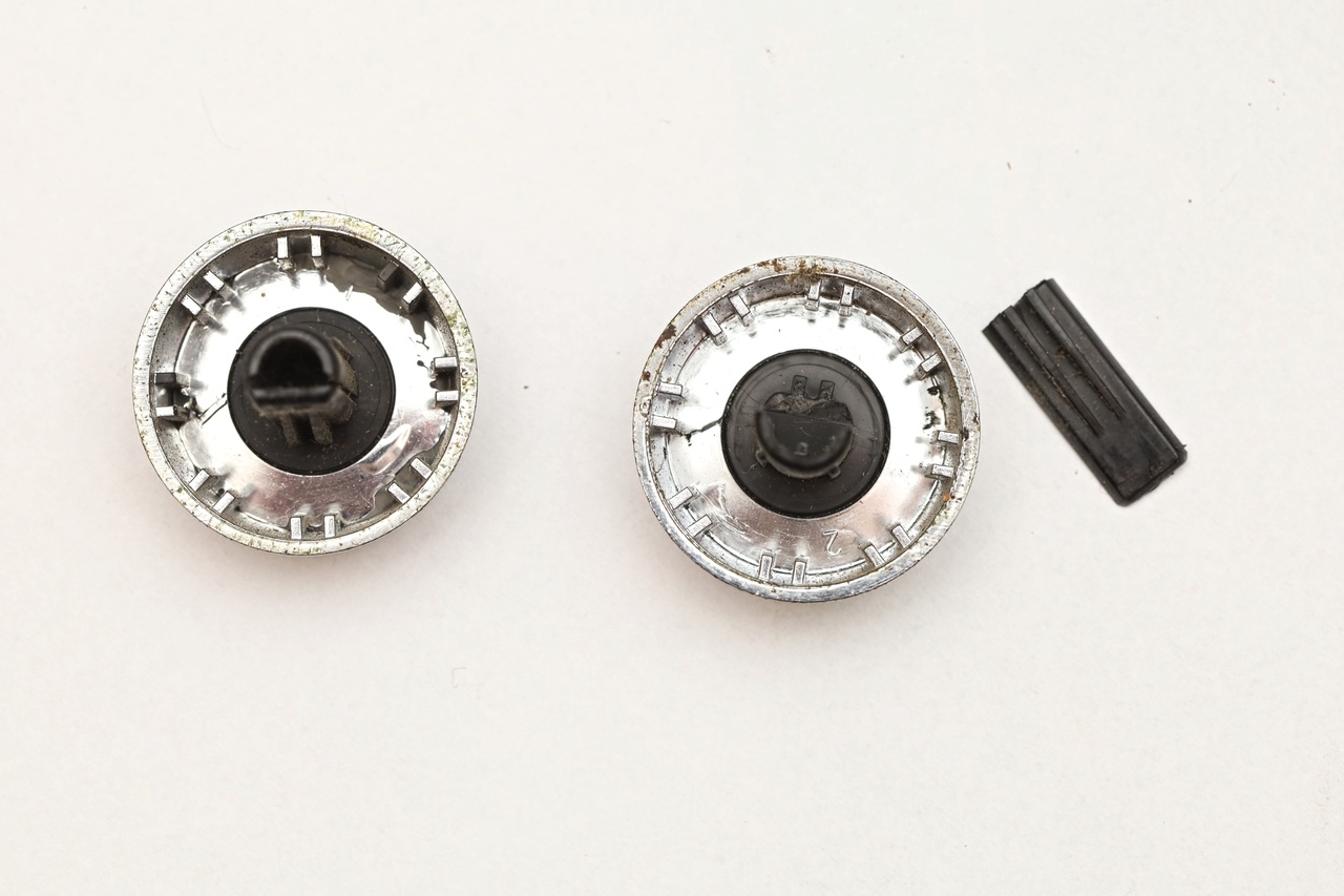

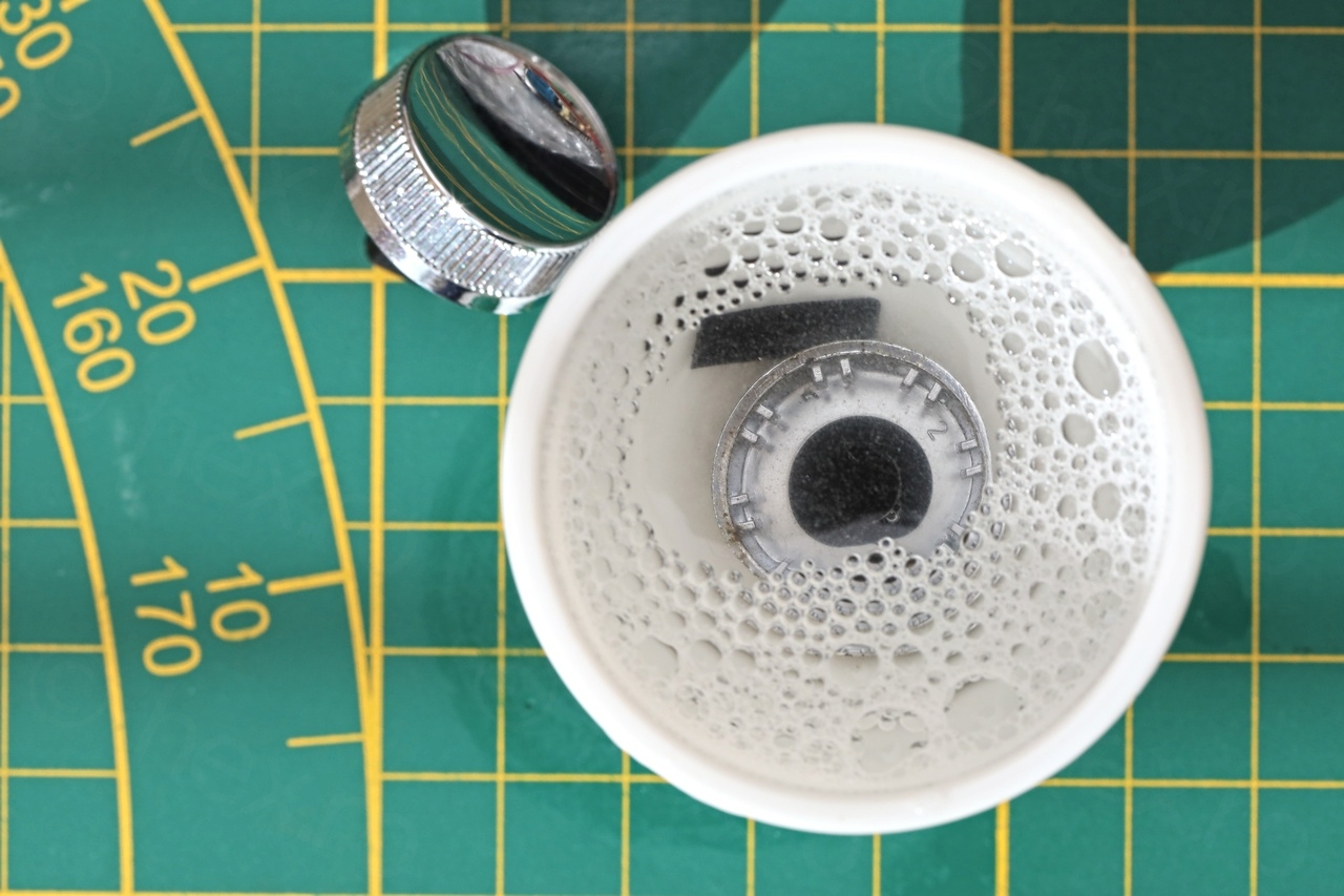
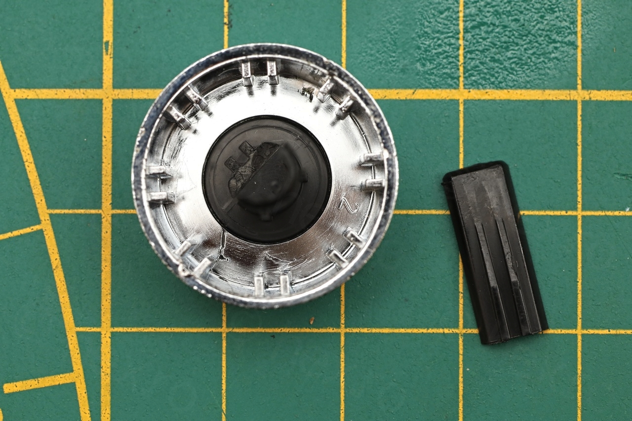
The buttons were dirty as the whole radio … thus before gluing back the broken part, I thoroughly cleaned the button.
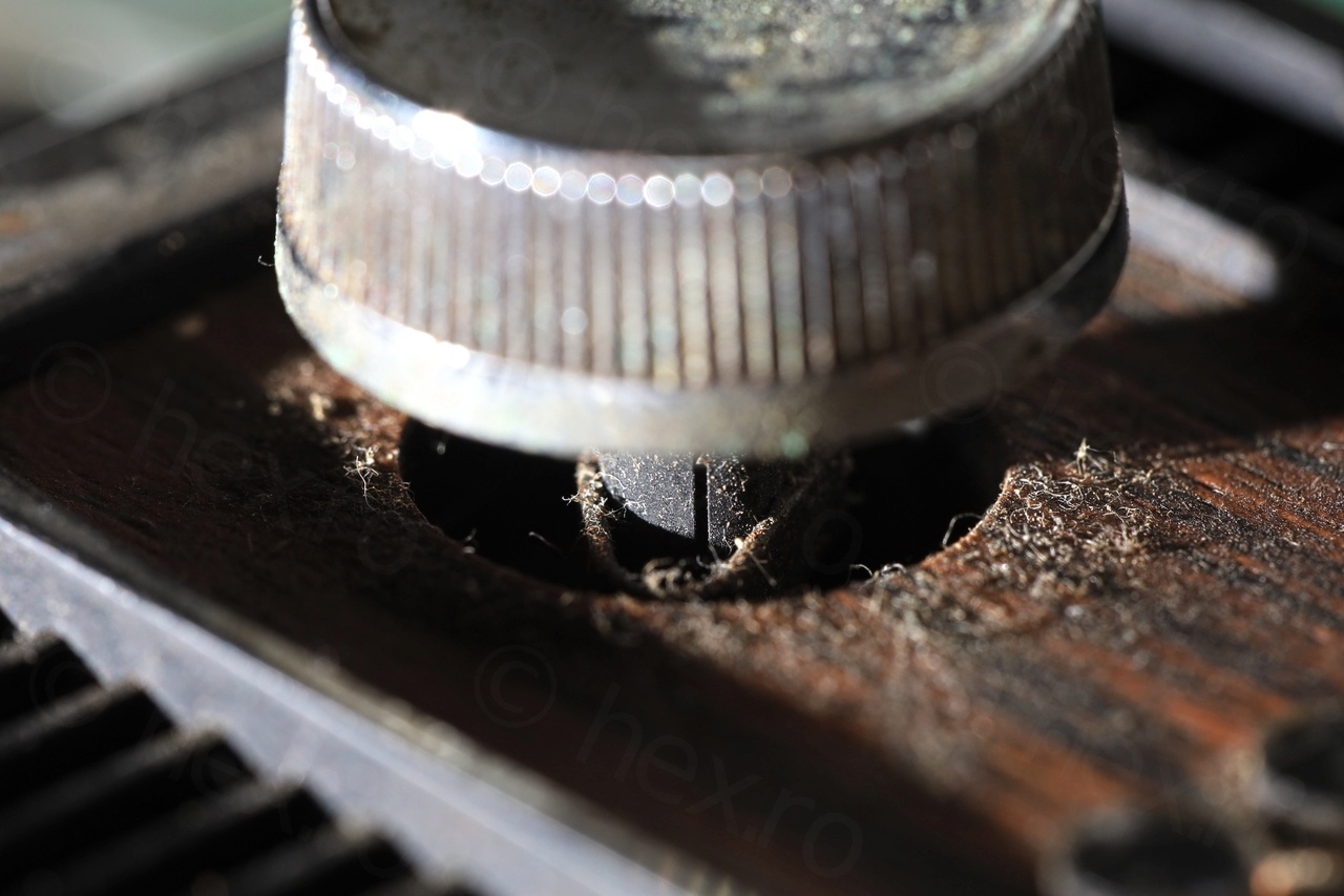
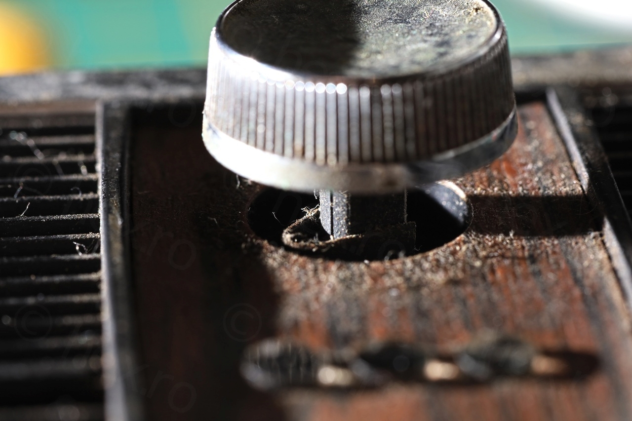
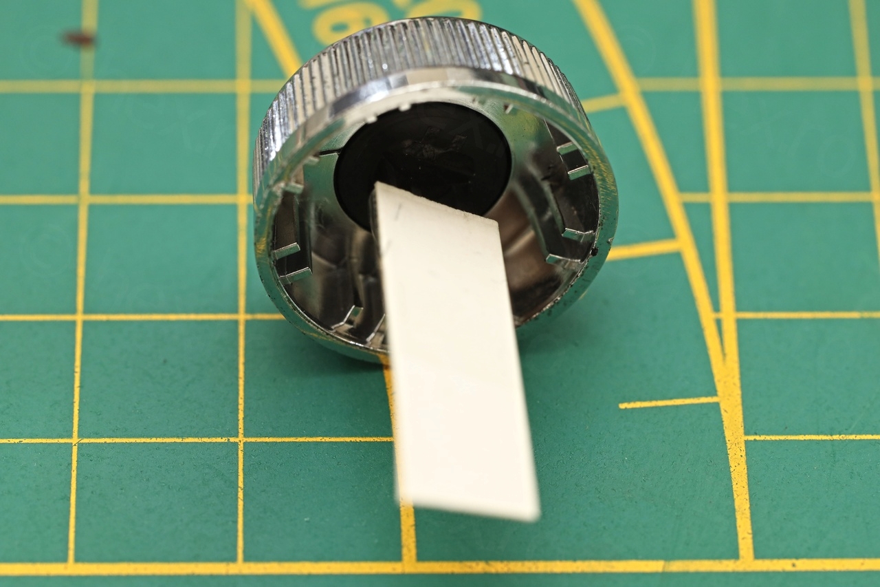
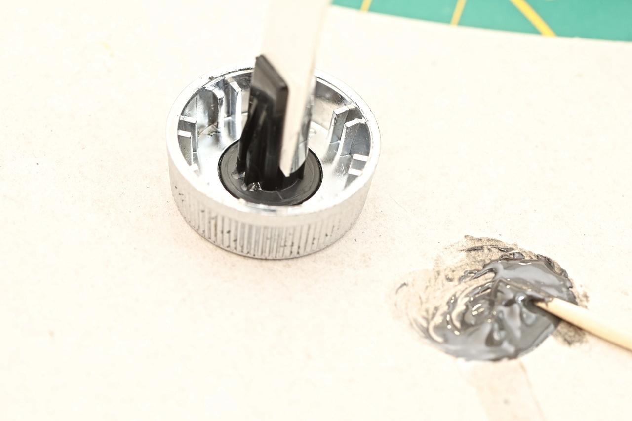
The other problem was that there was a bit of gap between the two parts of the shaft. J&B Weld is soft when first applied, which means that it would be very difficult to align the broken part with its counterpart while keeping the gap.
I cut a piece of thick paper to sandwich it in between the two parts. Used some adhesive tape to keep the two pieces together while the glue was curing:
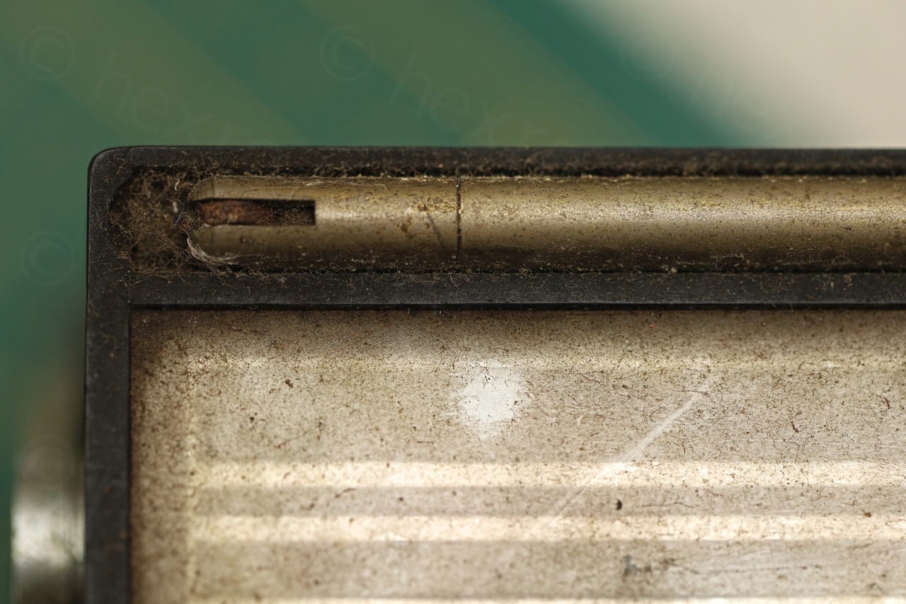
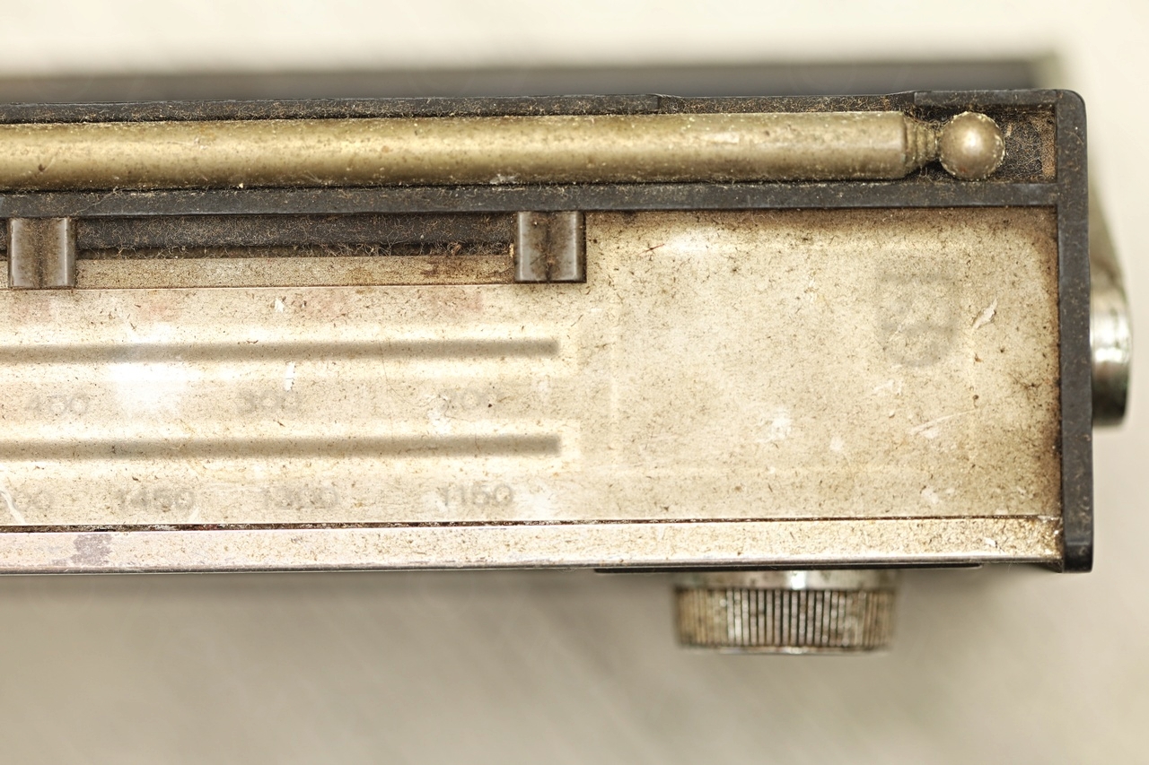
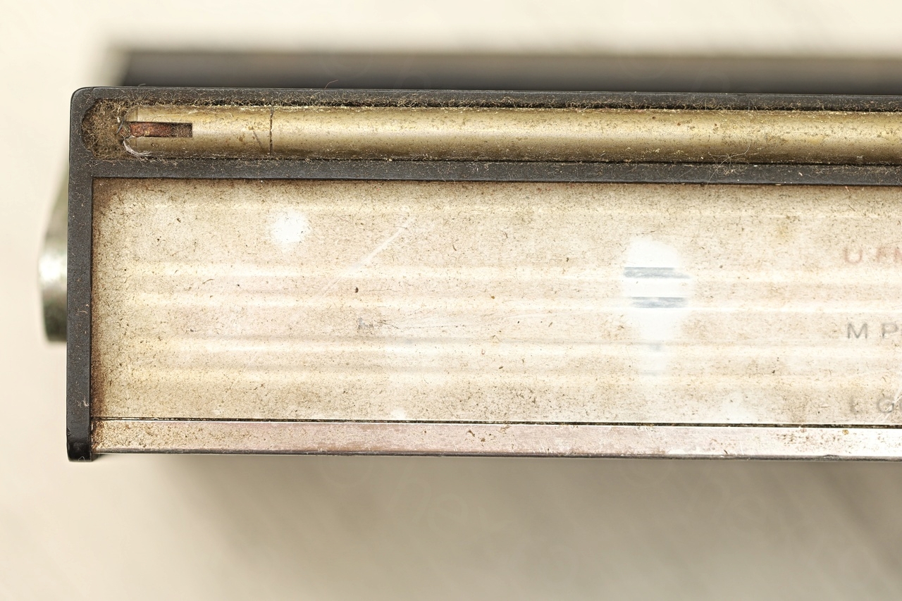
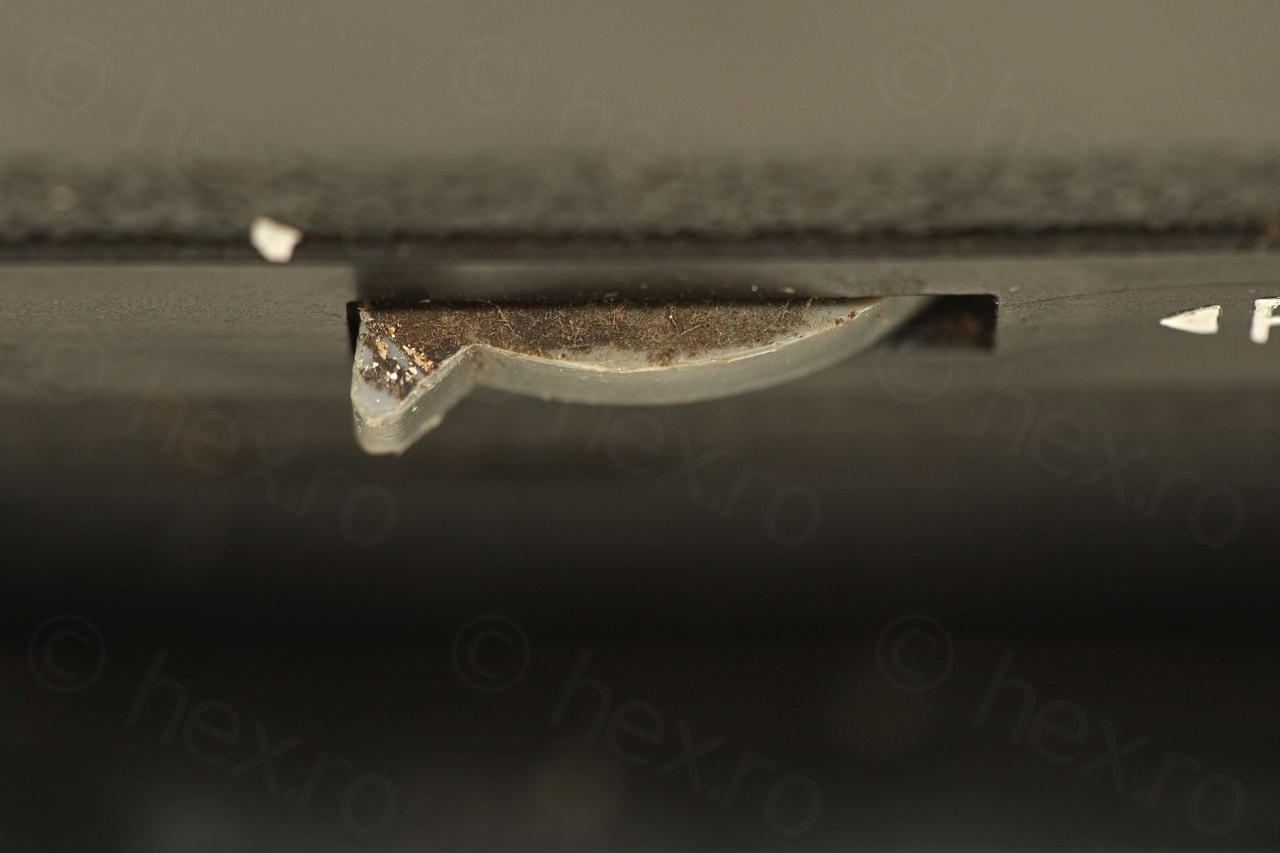
Cracked Dial Scale
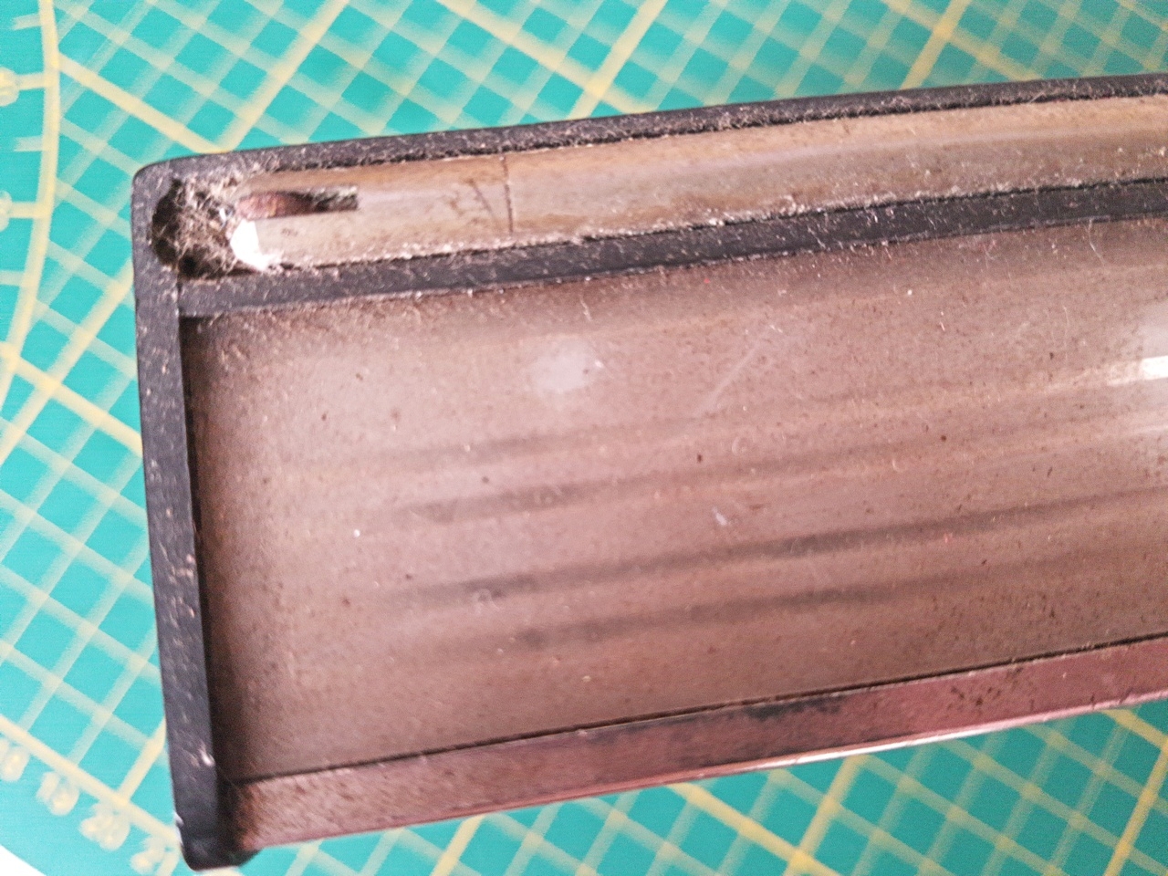
The trouble with these very old radios is that plastic is brittle and I doubt they design them to last for so long. While dismantling the radio, I noticed that one side of the dial scale fell off 🙁
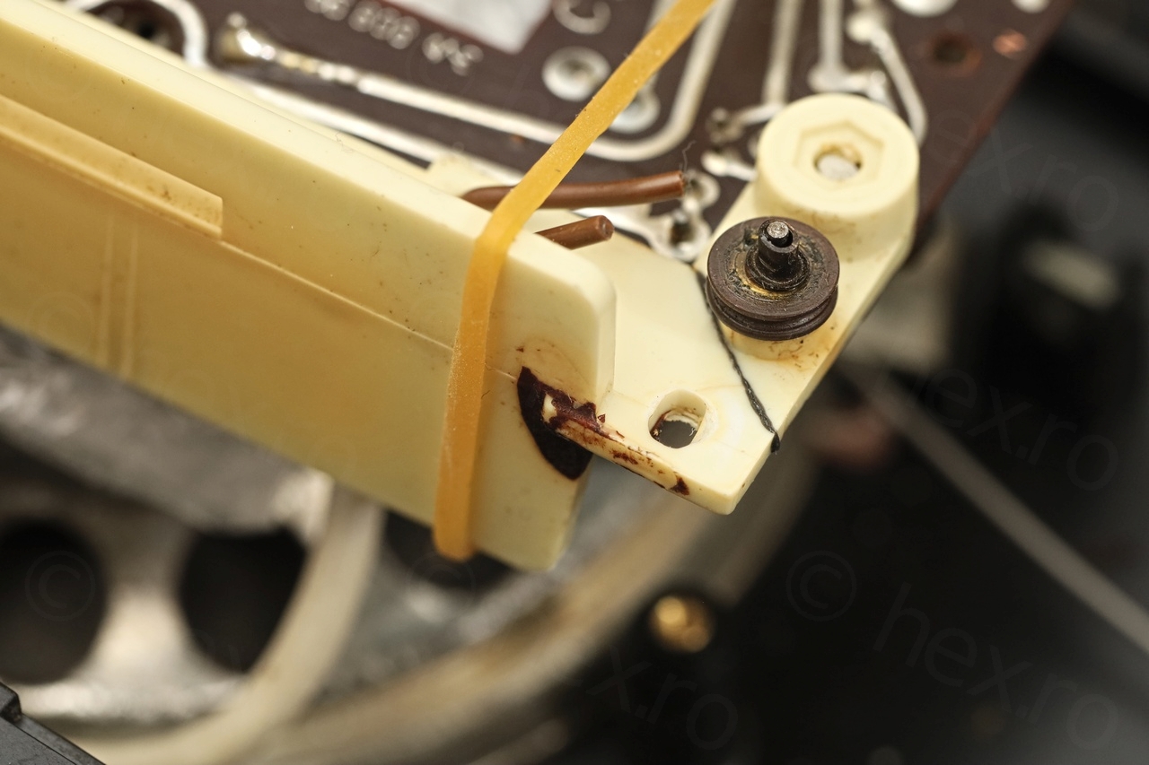
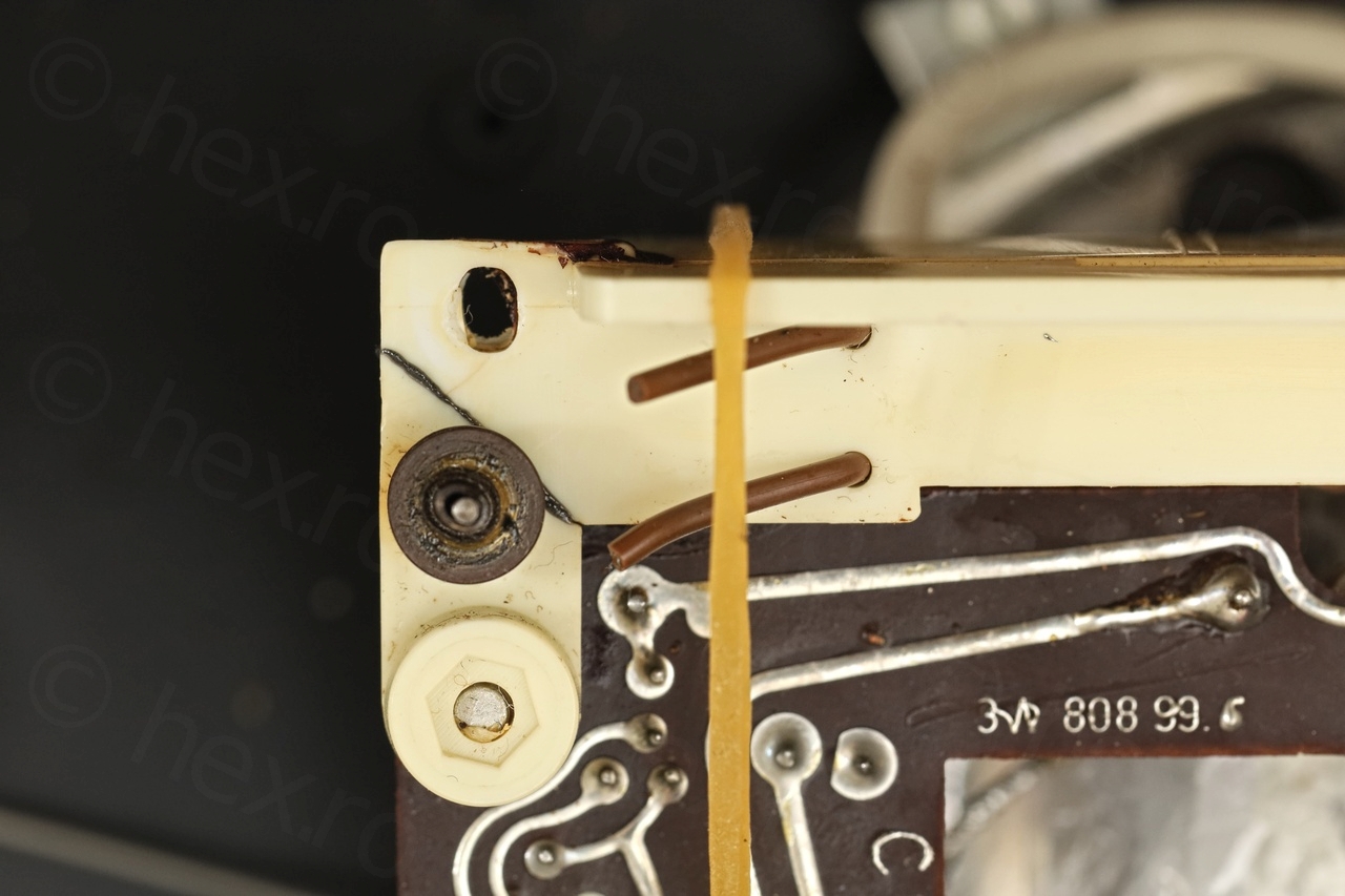
On closer inspection, it looks a combination of rust has cracked the part:
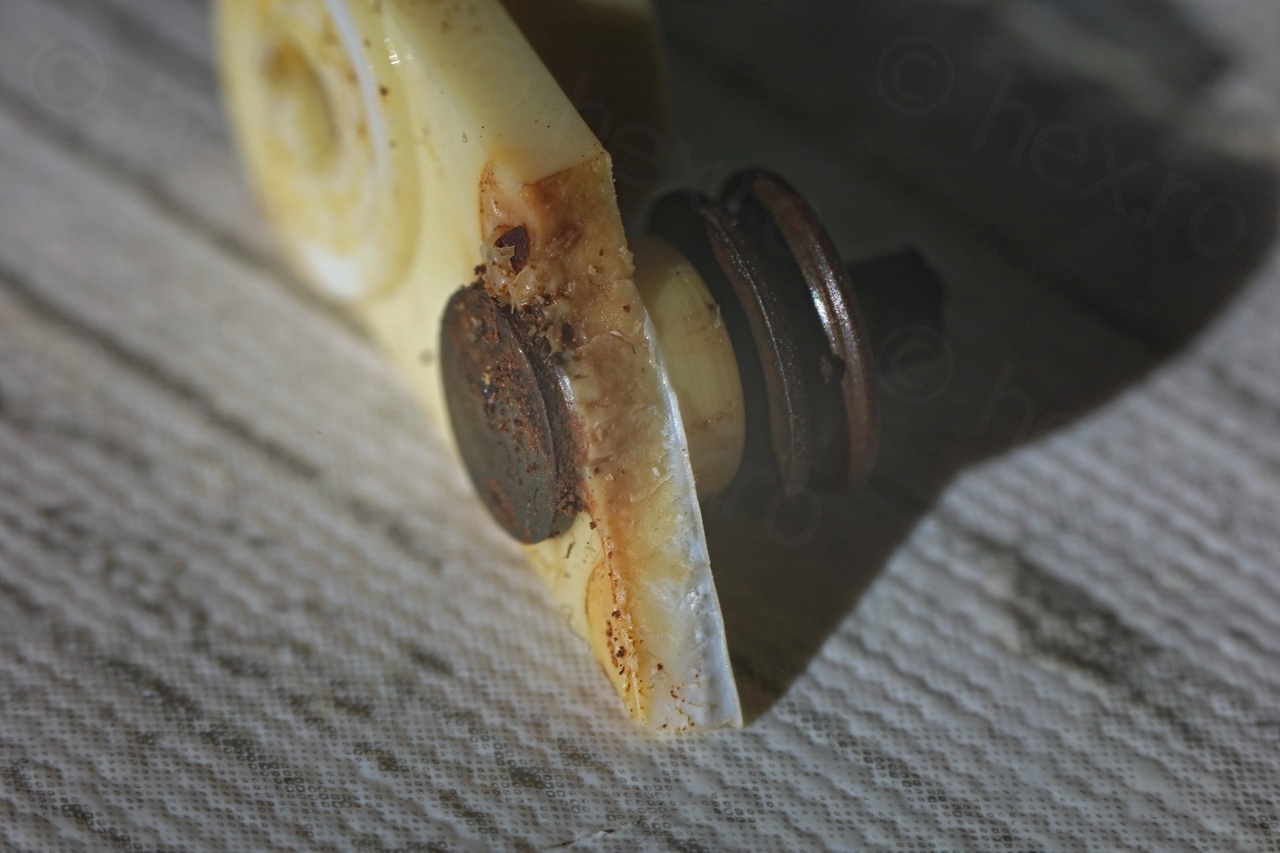
Some Isopropyl Alcohol later and a rubber band attached to keep it secured as the J&B Welds cures:

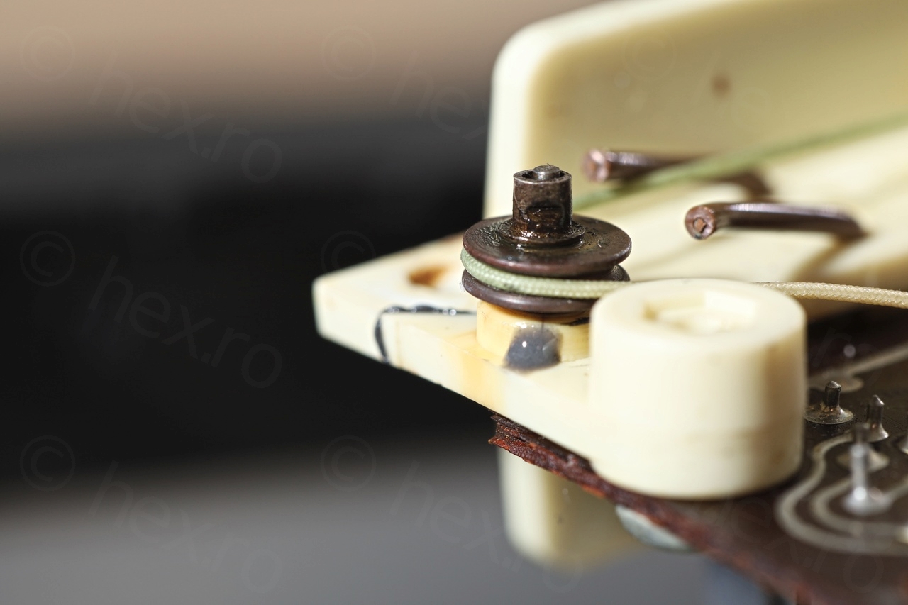
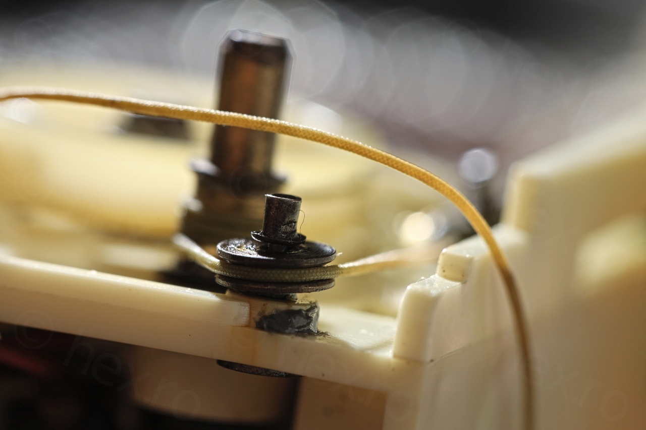
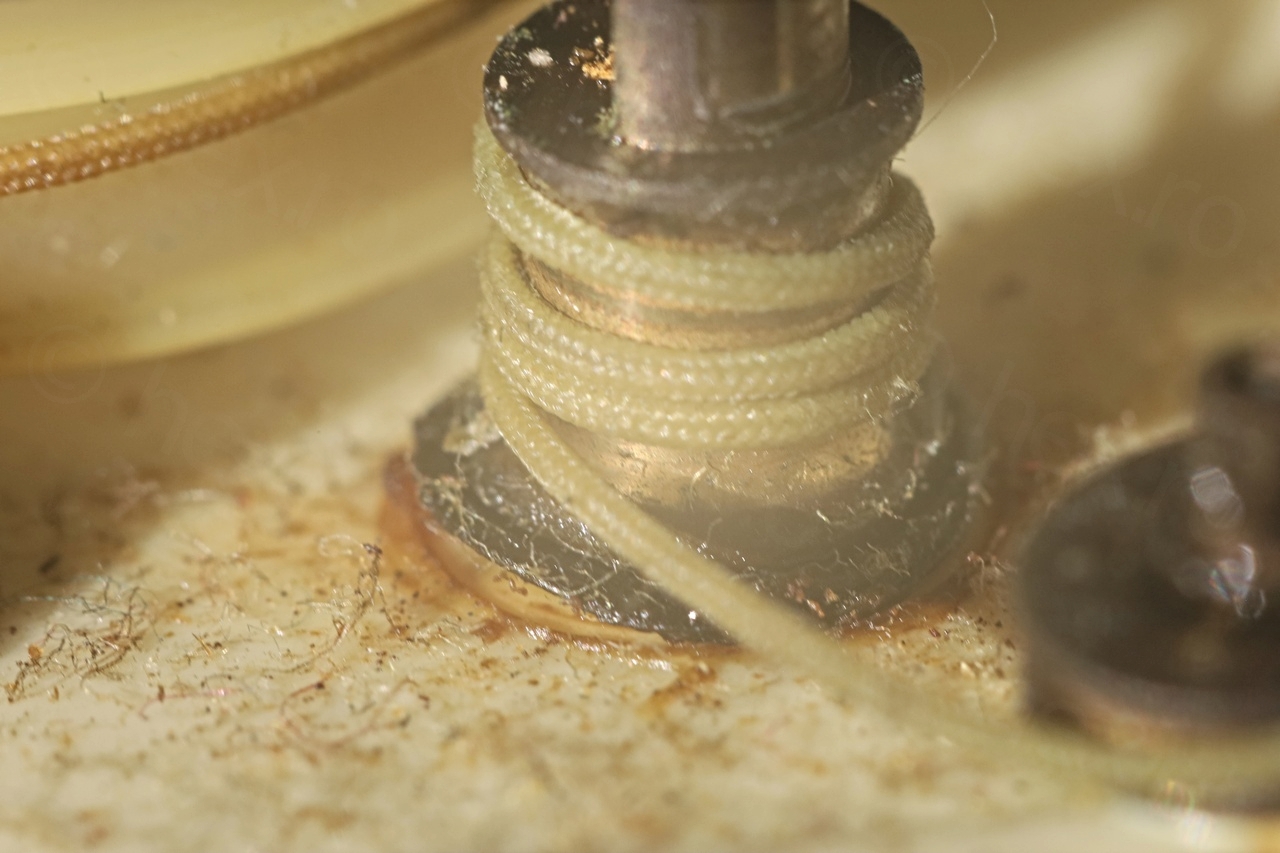
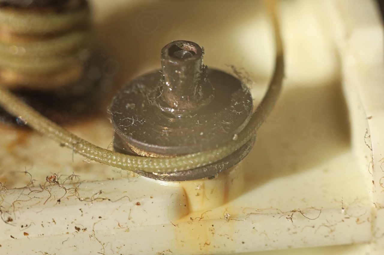
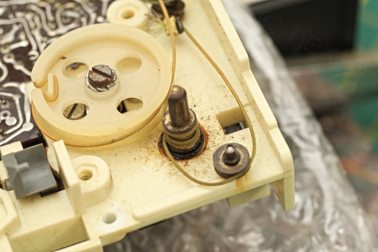
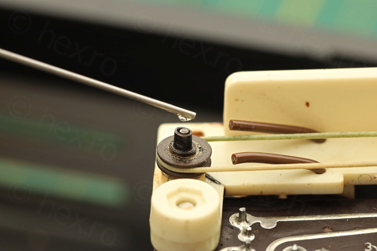
Of course, the dial cord had to be taken apart to work on the dial scale and I had to re-thread it after. The spring was very tight .. While having the dial string unthreaded – I proceeded with more cleaning and lubing:


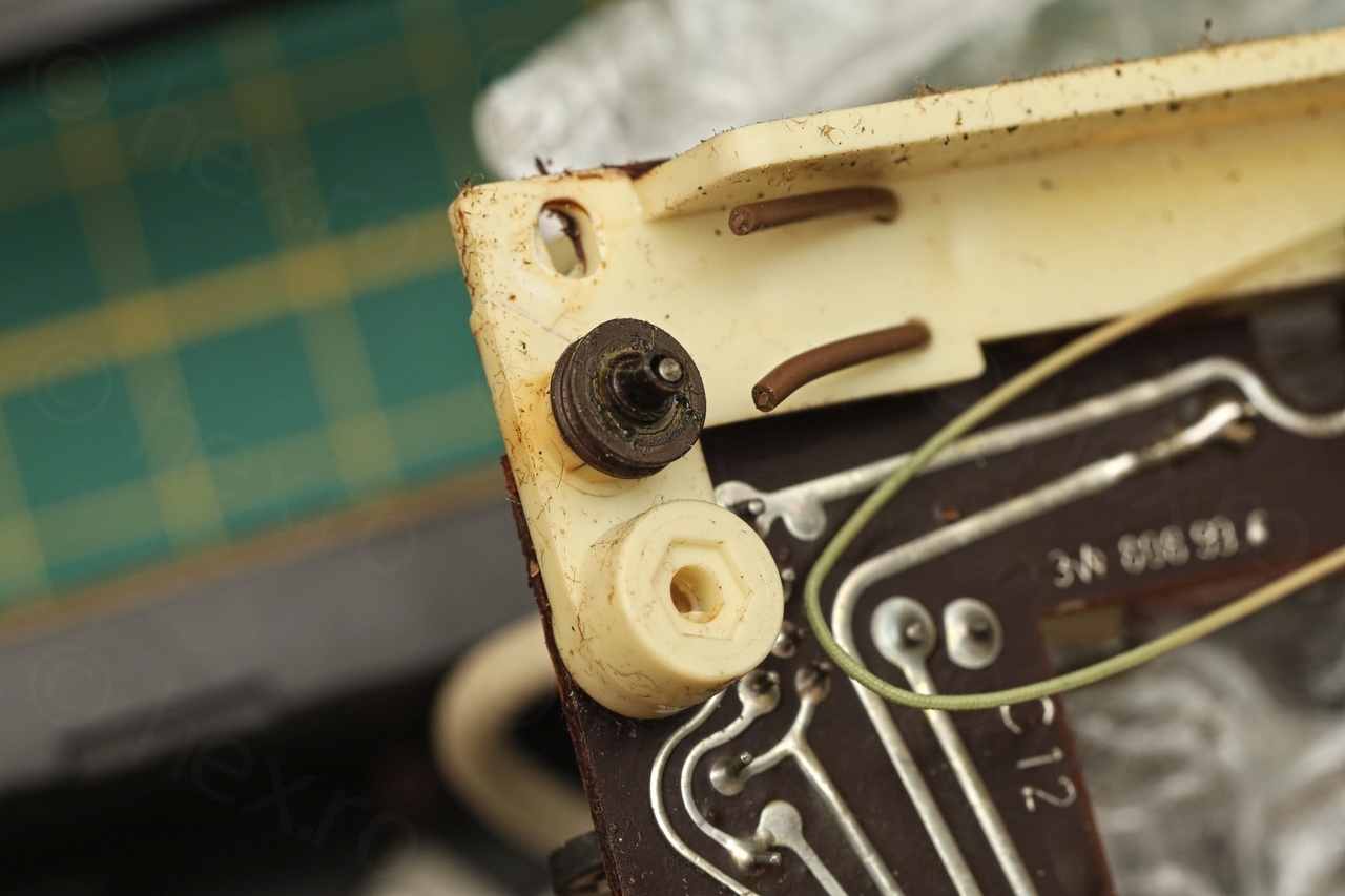
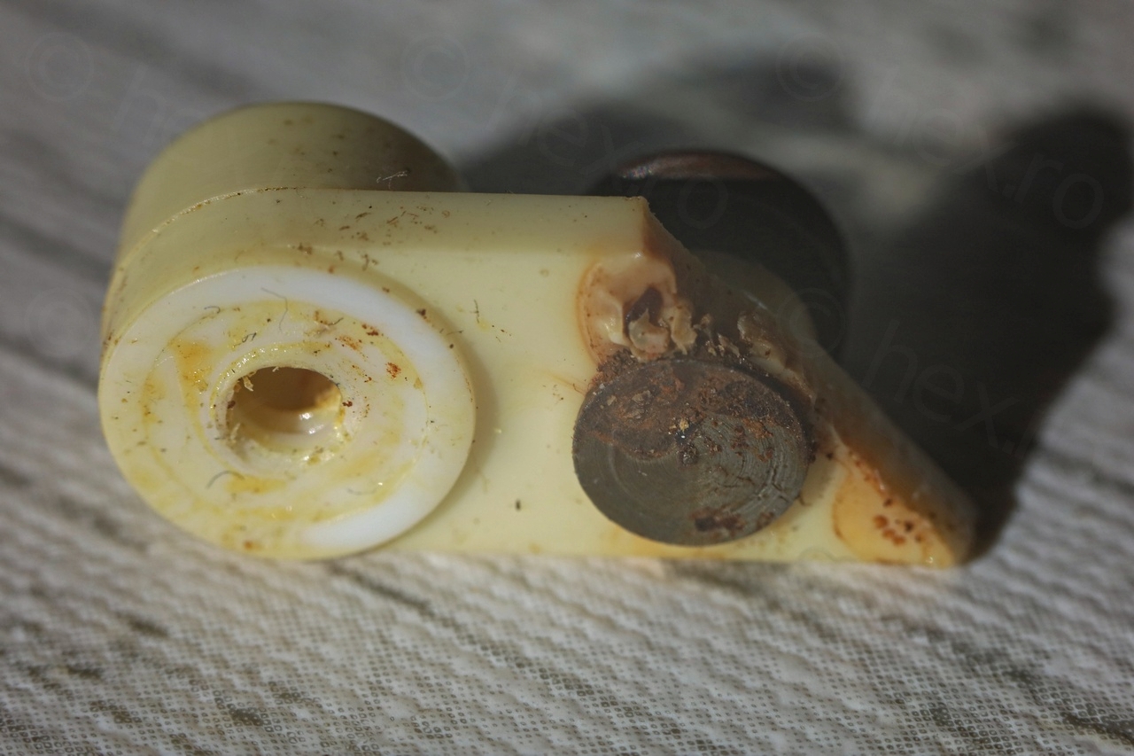
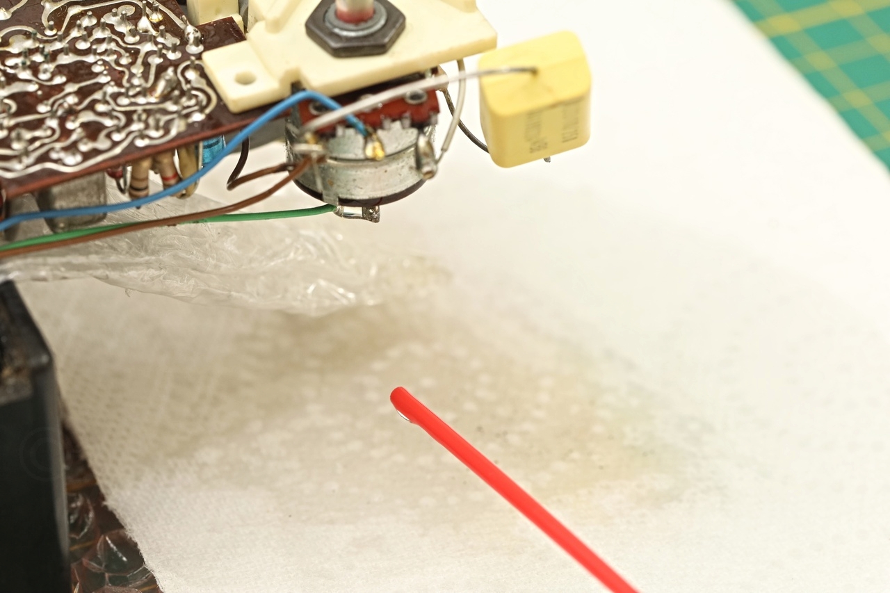
Rebuilding the Volume Potentiometer
Becoming more confident that this will end up being a successful restoration, I needed to tackle the Volume Potentiometer. On/Off switch wasn’t working and turning the Volume made the radio crack very loud.
I first started by drenching it in Contact cleaner:

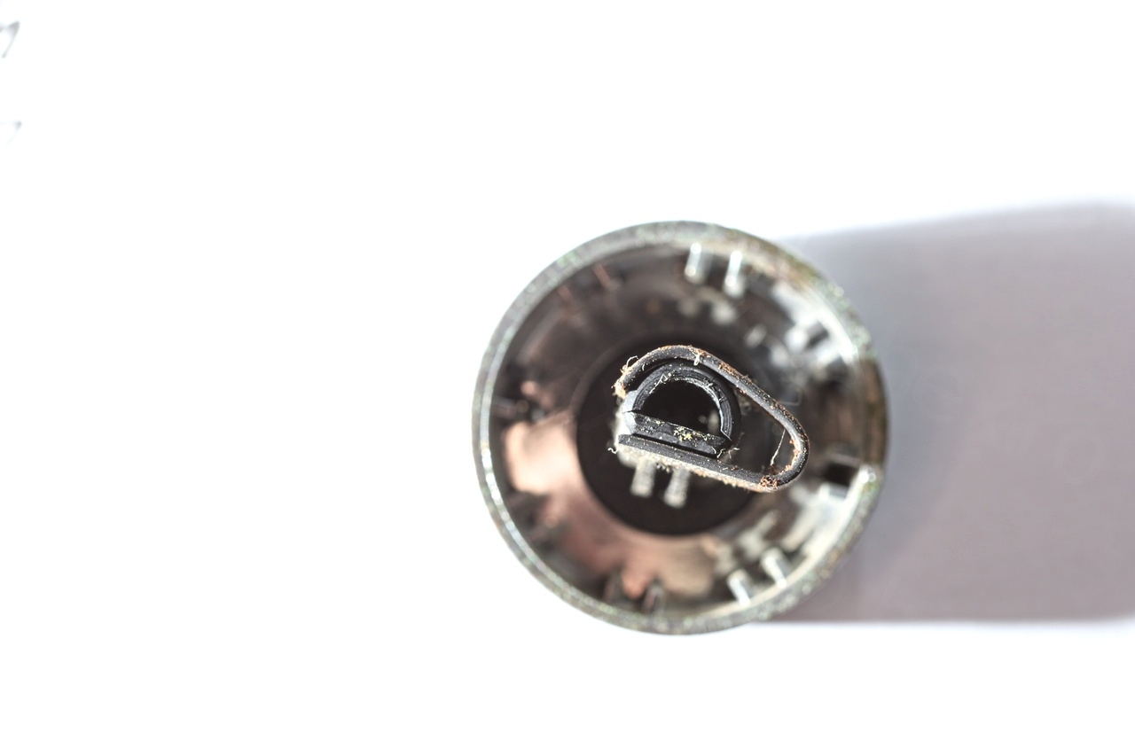
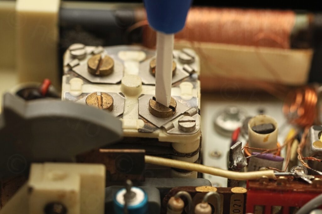
While this eliminated the crackling when adjusting the Volume, it still didn’t fix the On/Off issue, thus, I had to open it apart and have a look:
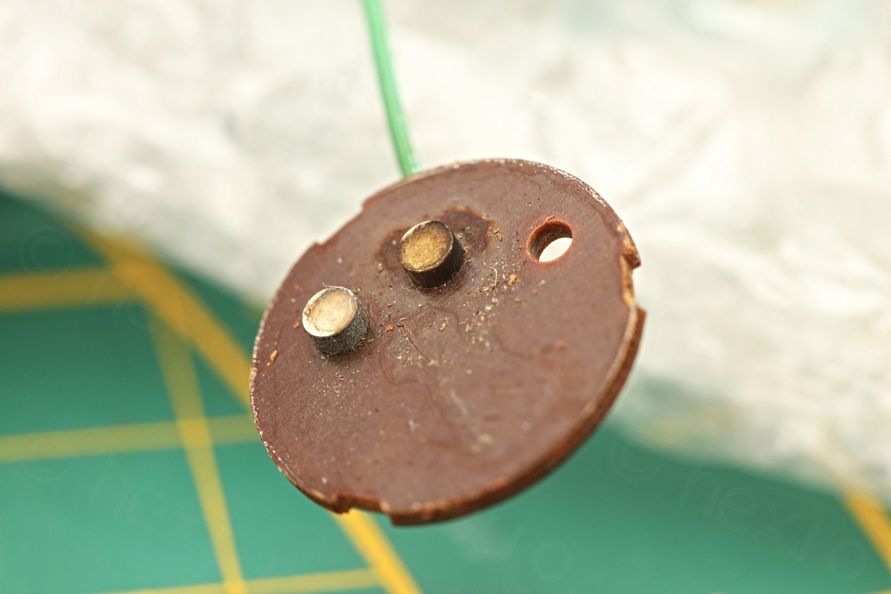

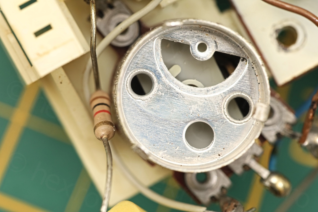
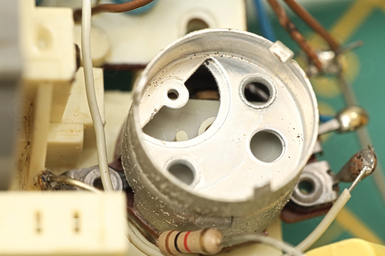
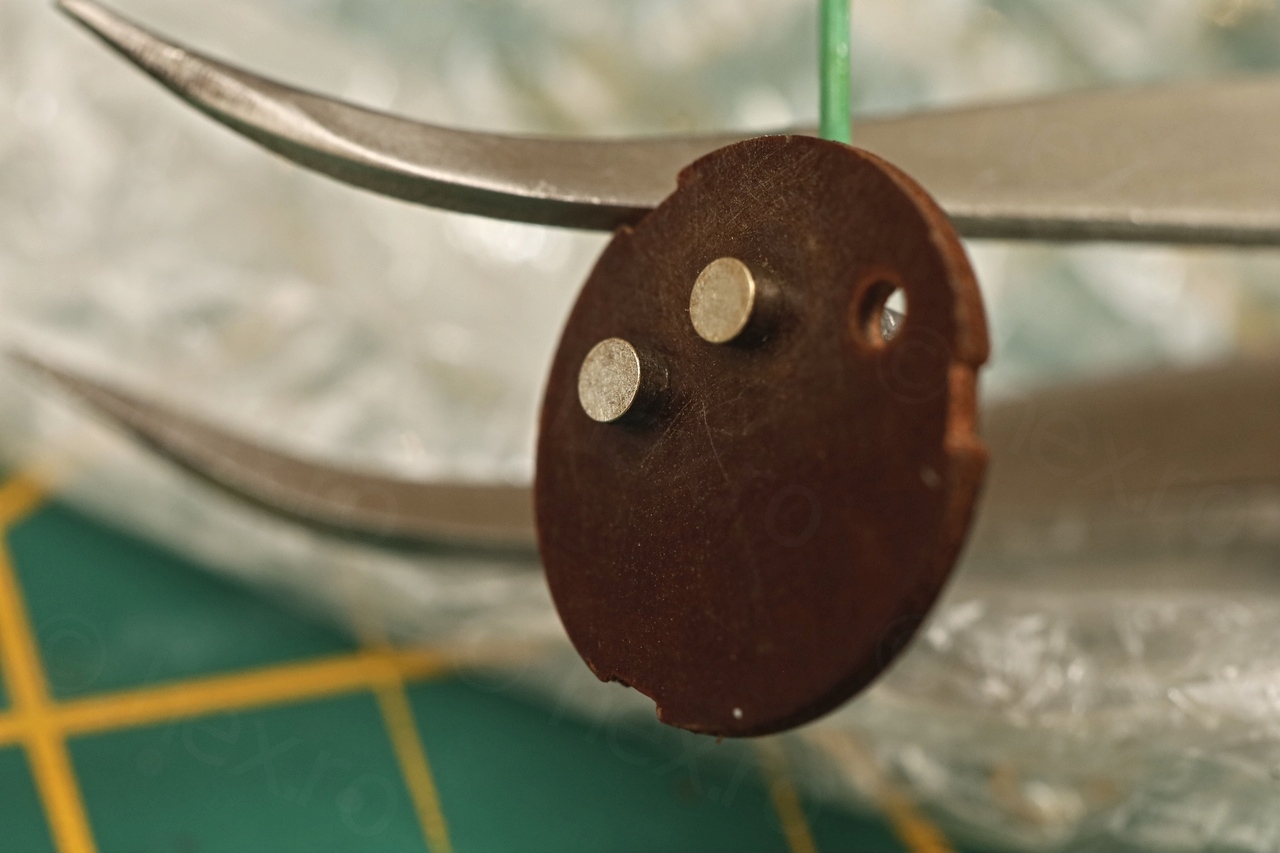
I realized there was no hope for the Contact Cleaner to ever get the thick black oxidation apart. With a thin steel brush I was able to scrub the two posts as well as the little moving part:
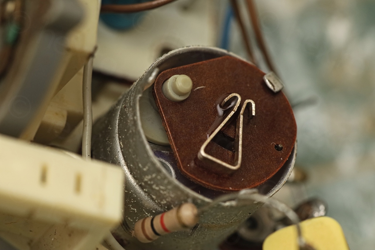

I put it back together which was a little fiddly – but it worked perfectly. Not sure if I did well putting a little dab of sewing machine oil, the whole assembly seem to need it – but I have lost the positive ‘click’ sound as potentiometer is turned on. But if it resists better to corrosion ..
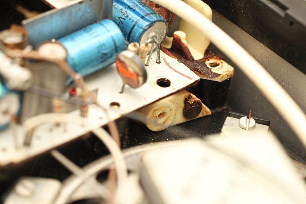
Re-gluing lifted traces
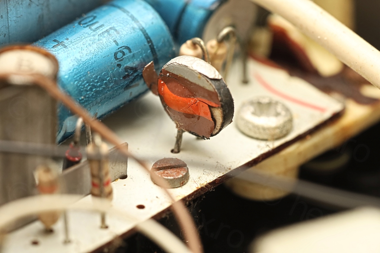
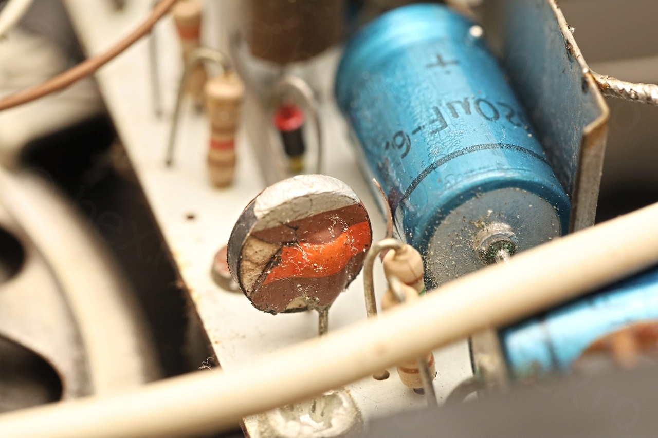
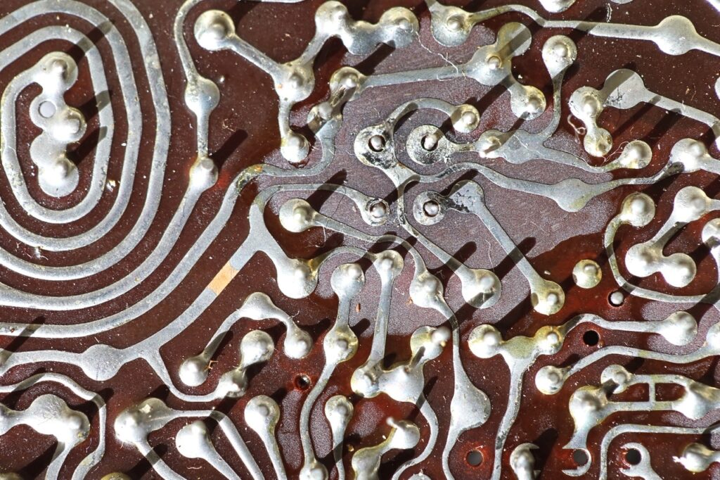
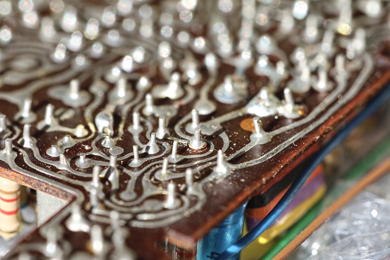
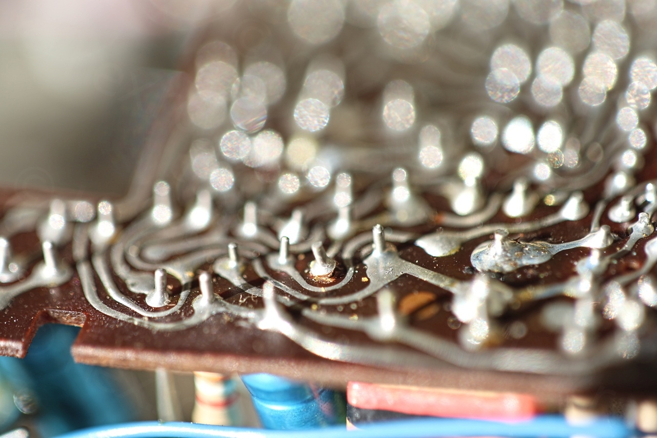
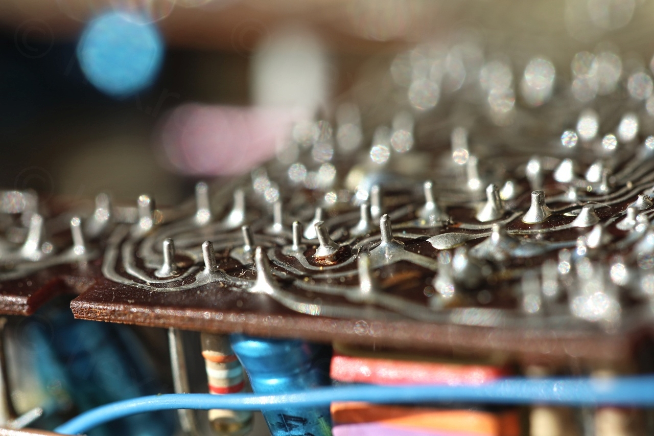
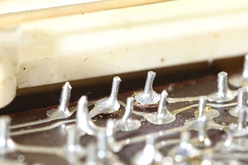
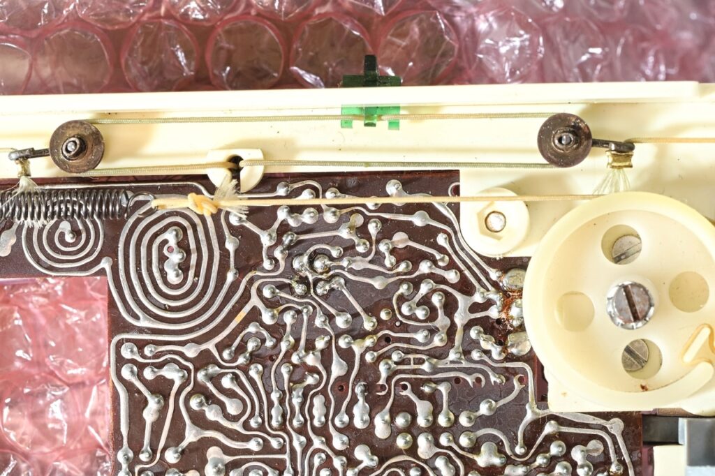
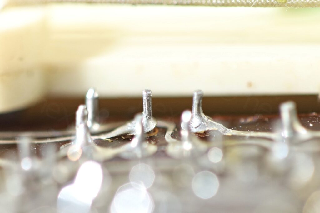
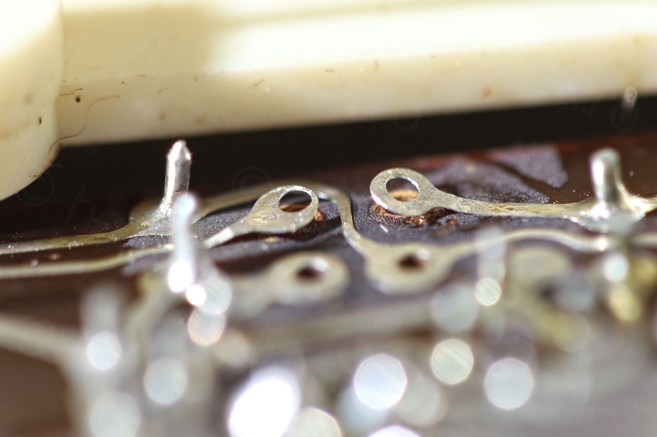
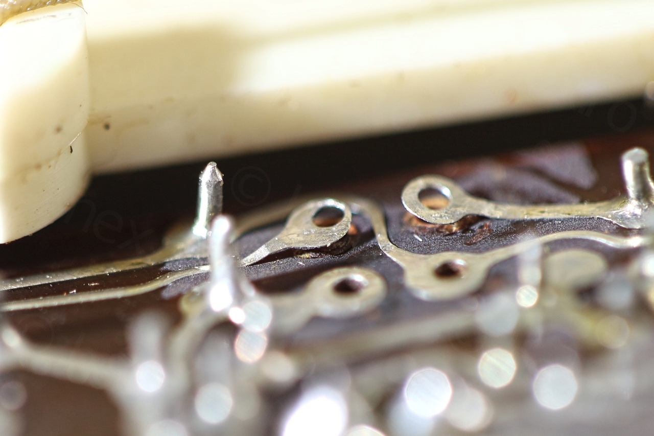
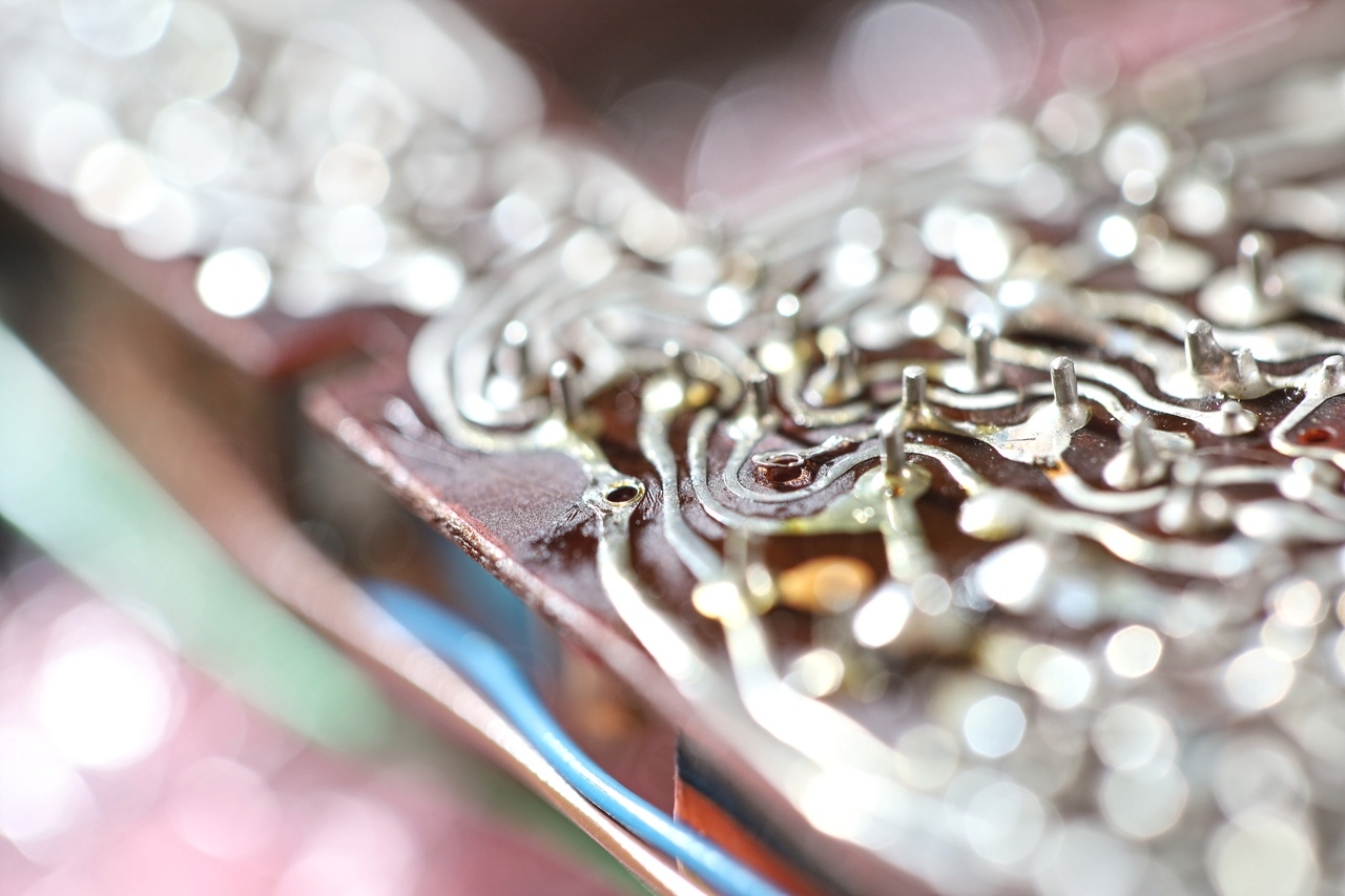
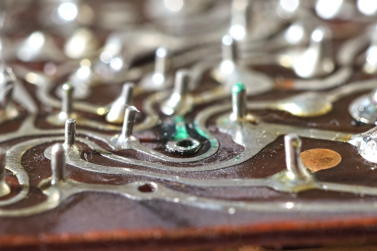
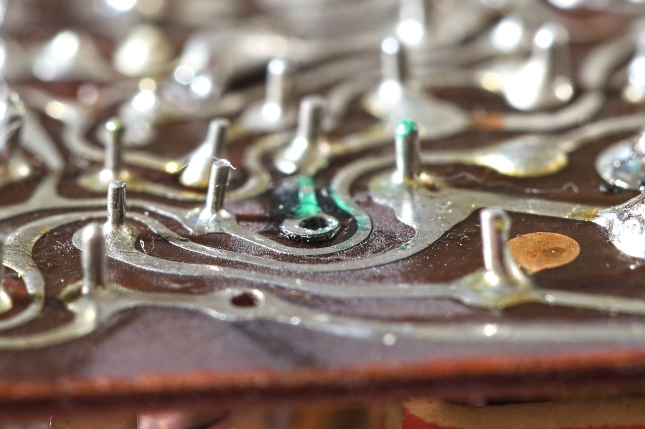
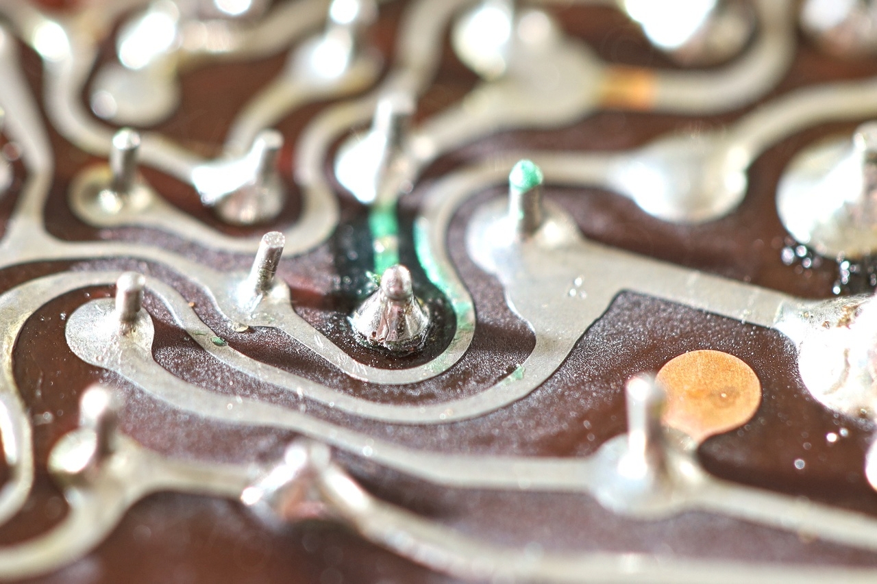
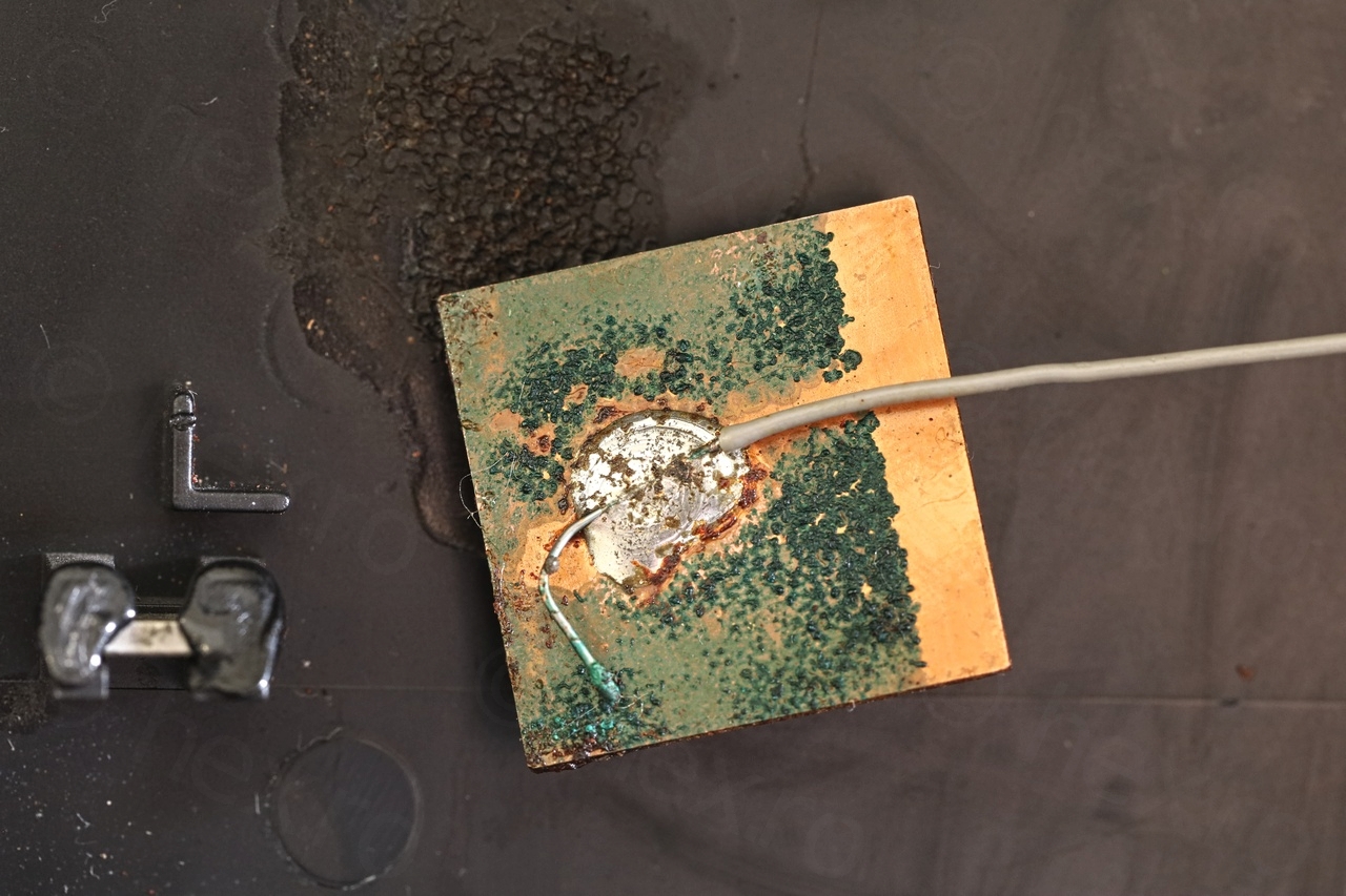
I had already noticed that the circuit board was in a poor condition even before removing the TS402 transistor. The circuit board was being slowly eaten away:
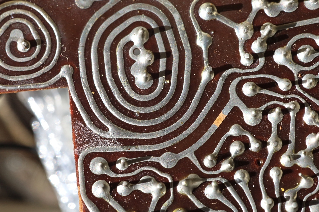
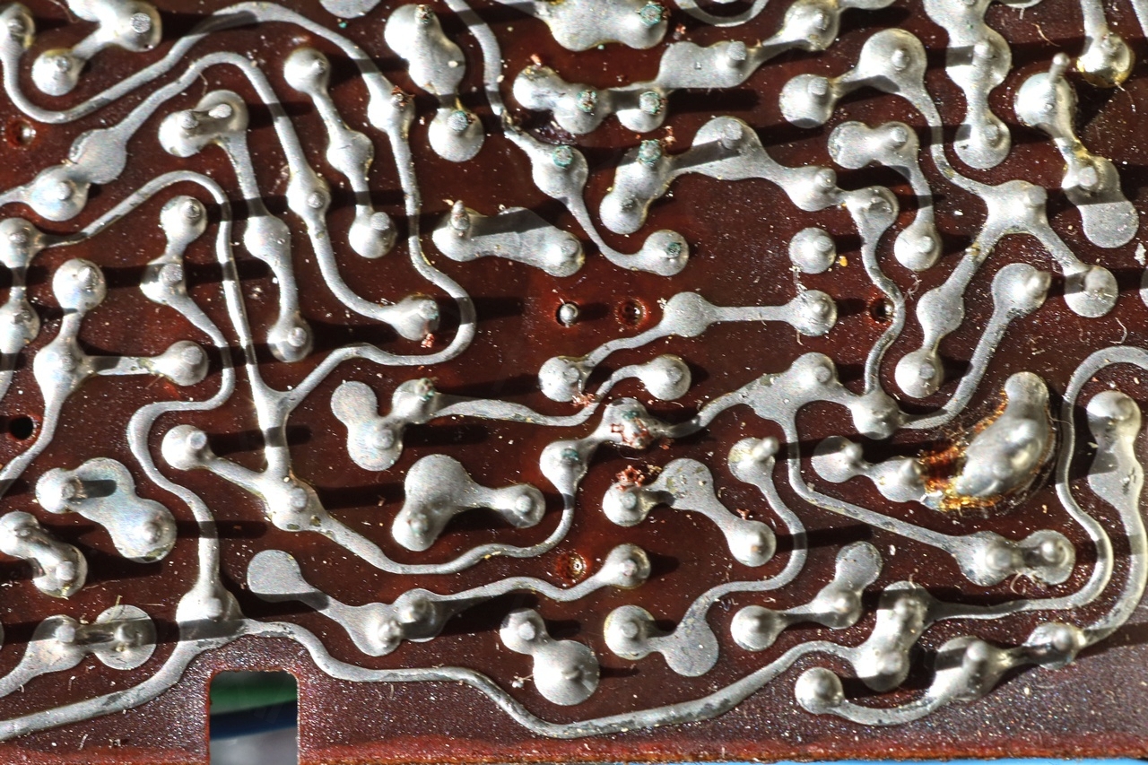
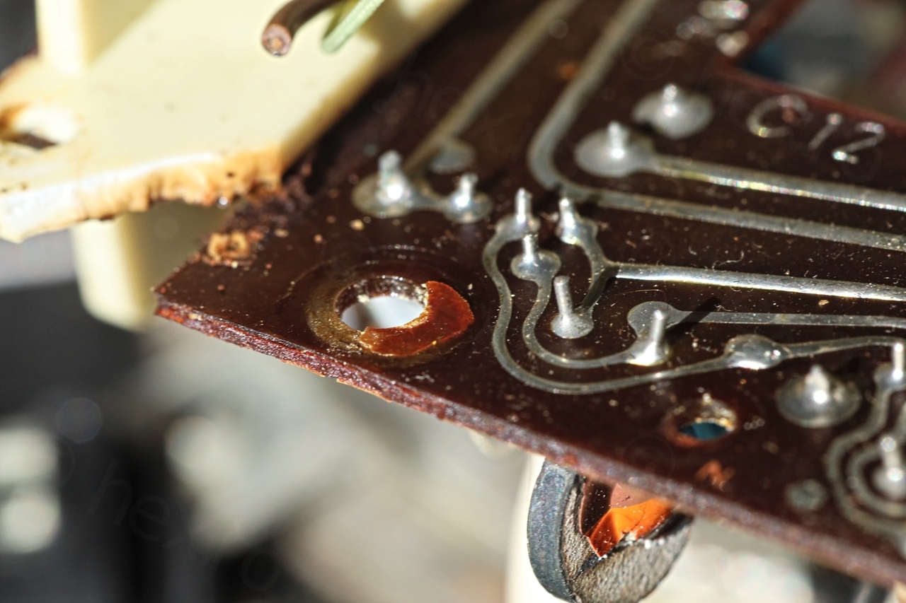
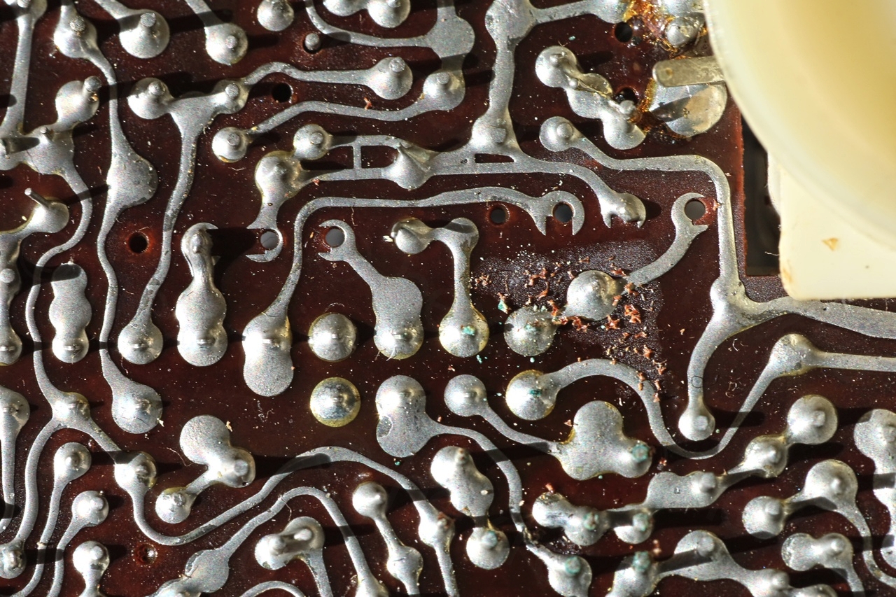
… and I spotted a lifted trace that was connected a capacitor pin:
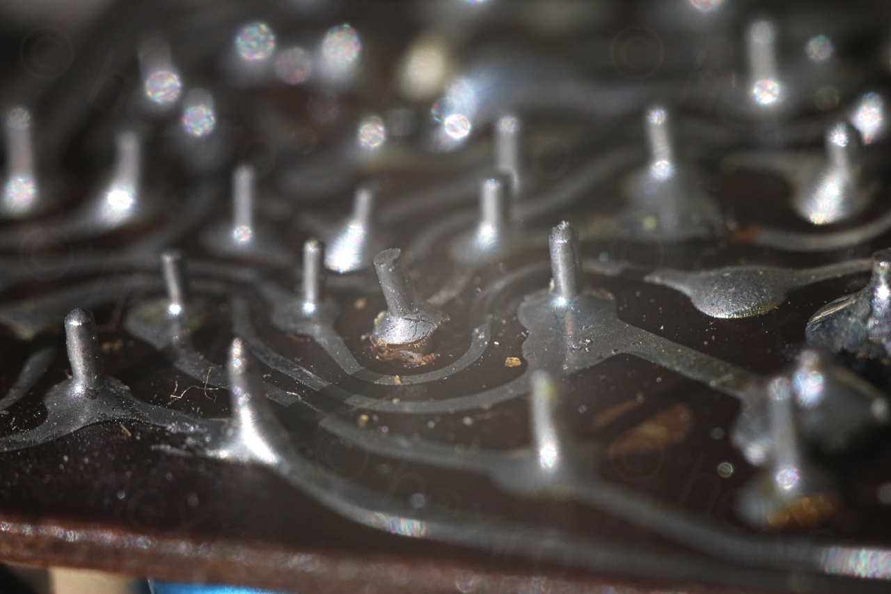
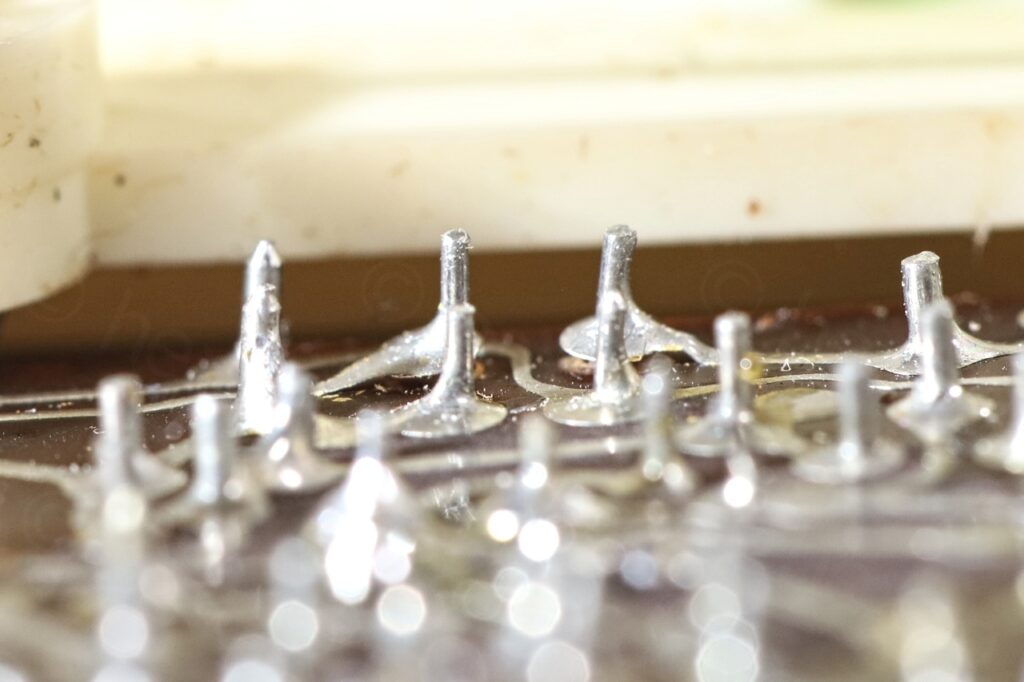
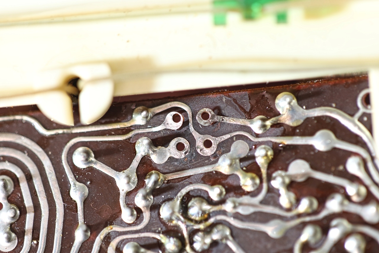
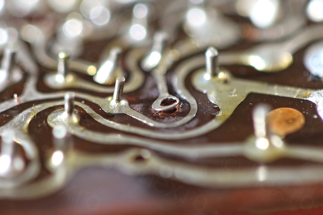
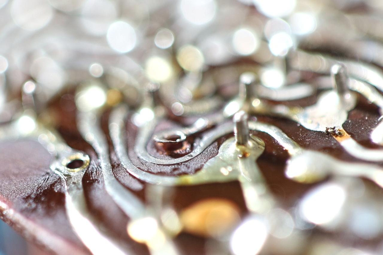
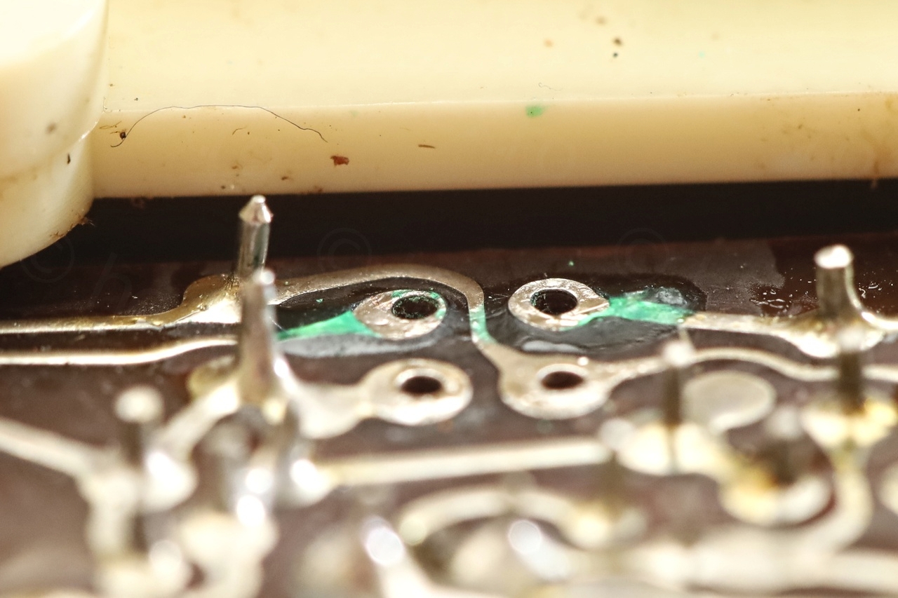
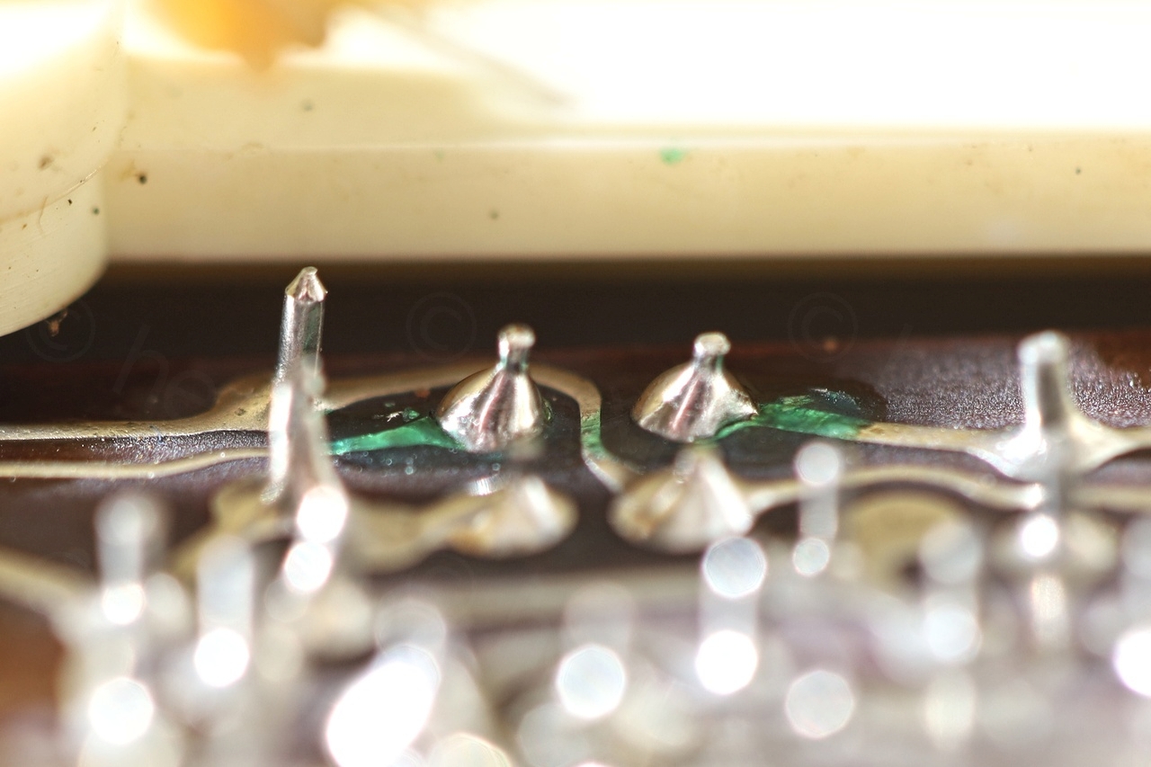
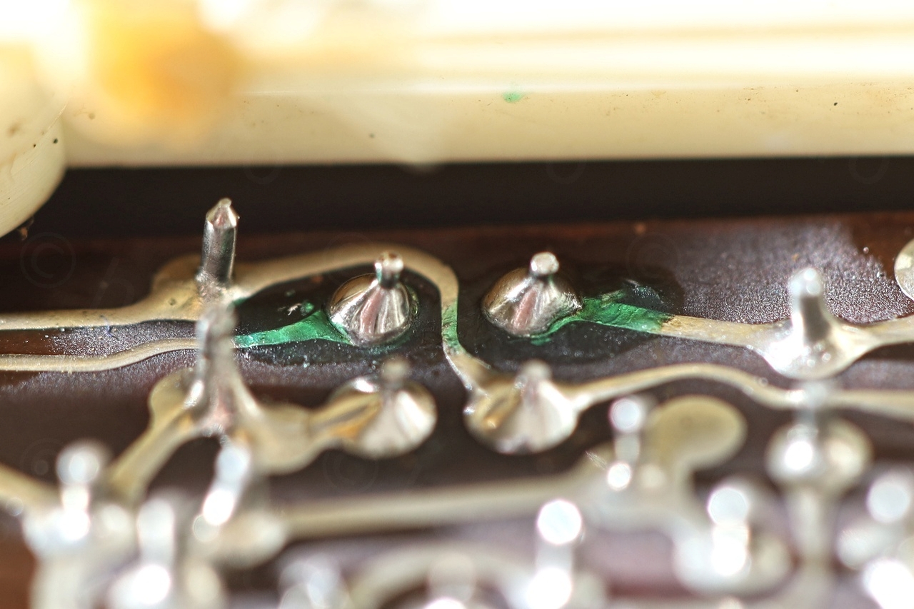
A much problem appeared after replacing the TS402. While attaching the little metal clip between TS402 and TS401, the pressure put onto TS401 got transferred to the board – causing two of its traces to also lift up:
I didn’t know how to glue these traces back onto the board, but few posts on the internet recommend and epoxy called CW2500 from Circuitworks. Meant for over-coating, it can also be used for under-coating. One advantage of CW2500 versus standard epoxies is that it resists few seconds to high temperatures – just enough time for you to solder the part back.
First cleanup of the area:

The next challenge was how to keep the traces down while the epoxy cures ? I had to clean underneath the traces too, which gave them an upwards look. CW2500 is rather liquid when applied and not strong enough to keep them down.
Anything I’d use to keep them pressed to the board would also solidify with the traces as the epoxy hardens, and when trying to remove it – traces would be torn too. Another concern was I didn’t want the epoxy to get into the drill hole where the pin should go through.
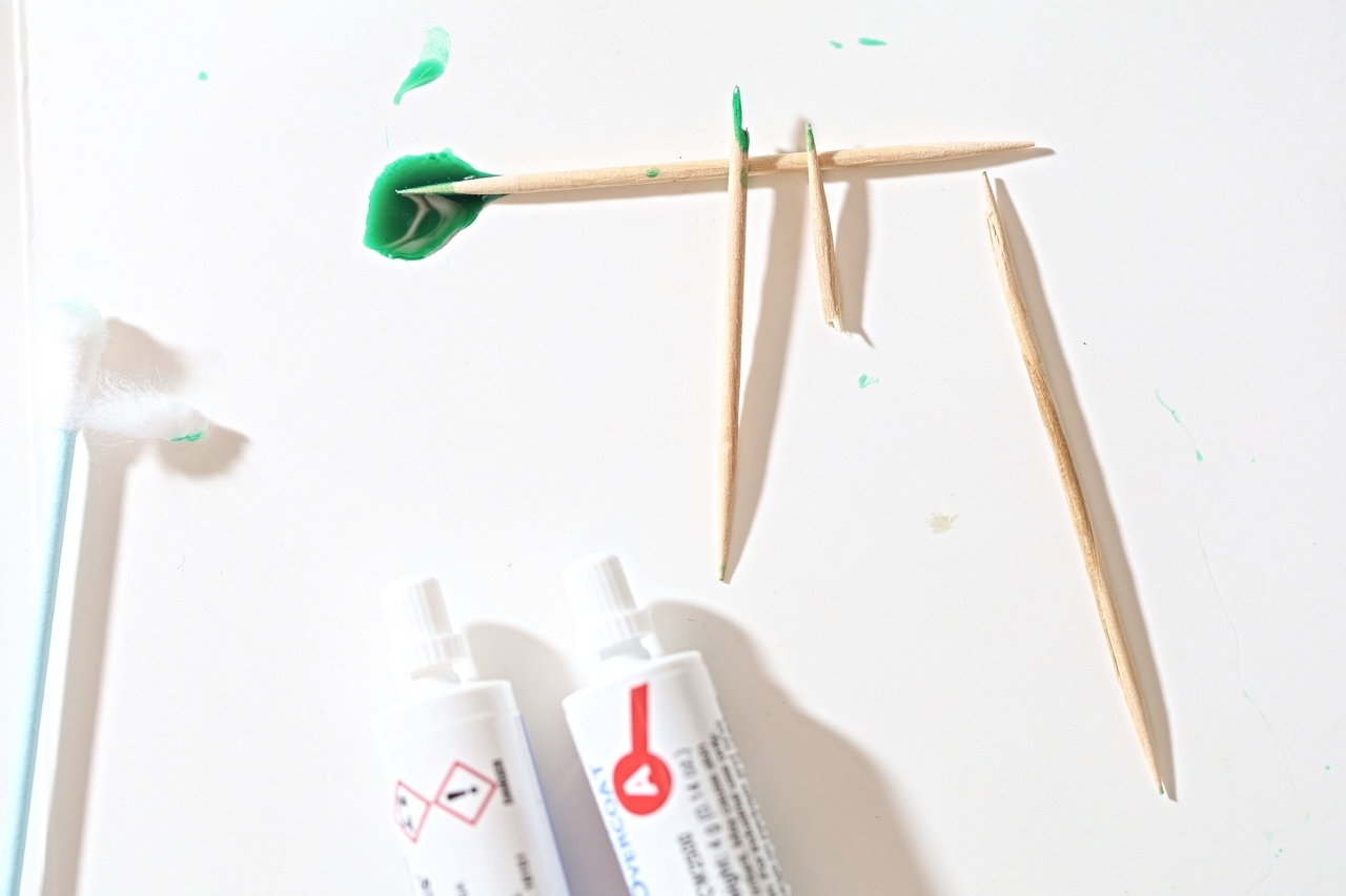
Eventually I went for toothpicks. They are easily drilled out in case they would have solidified with the epoxy, but being angled was allowing me to put pressure on the pads while still protruding through the drill hole.
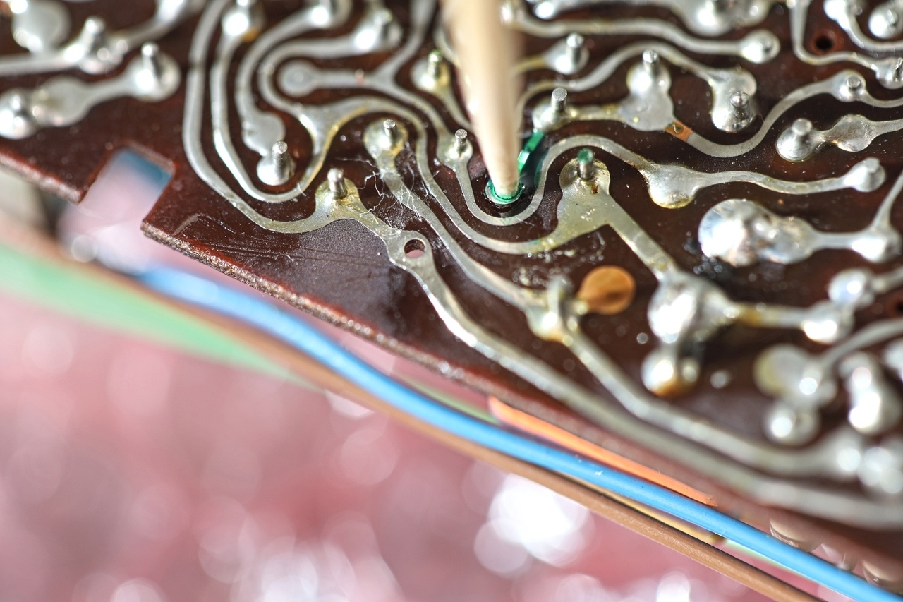
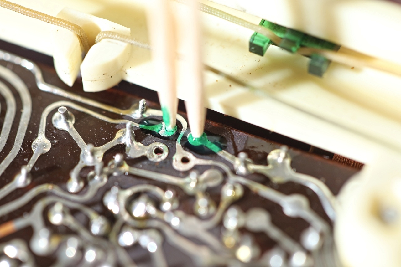
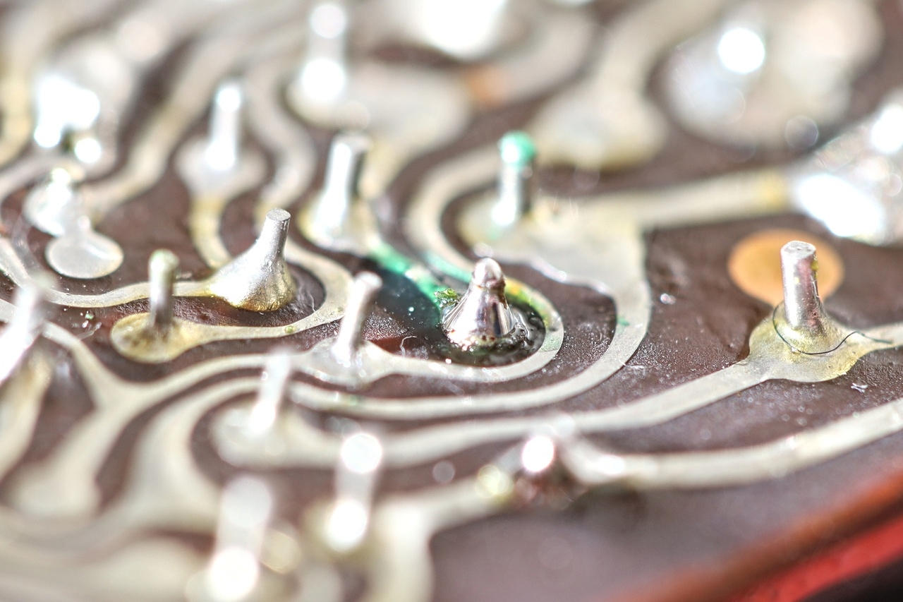
Turns out using CW2500 is very user friendly, about 3 hours into the room temperature curing process – the epoxy is hard enough to keep the trace down, but you can still scrape the pad with a sharp cutter or with toothpicks. I payed a lot of attention not to cut the trace nor to tear the pad in anyway during cleanup:

I was very pleased with the results – left it to cure for more than 16h. It was time to re-install the TS401 transistor as well as the capacitor. And do it quickly. TS401 is a Germanium AF124 transistor, they don’t like being overheated nor the epoxy would last long if heated too much. Using the iron at 350C – but made sure is plenty hot before applying heat. Also applied rosin to make it faster:
The epoxy did not break down and I was able to reinstall metal clip thermally connecting the two transistors together without lifting the glued traces!
Recapping it ?
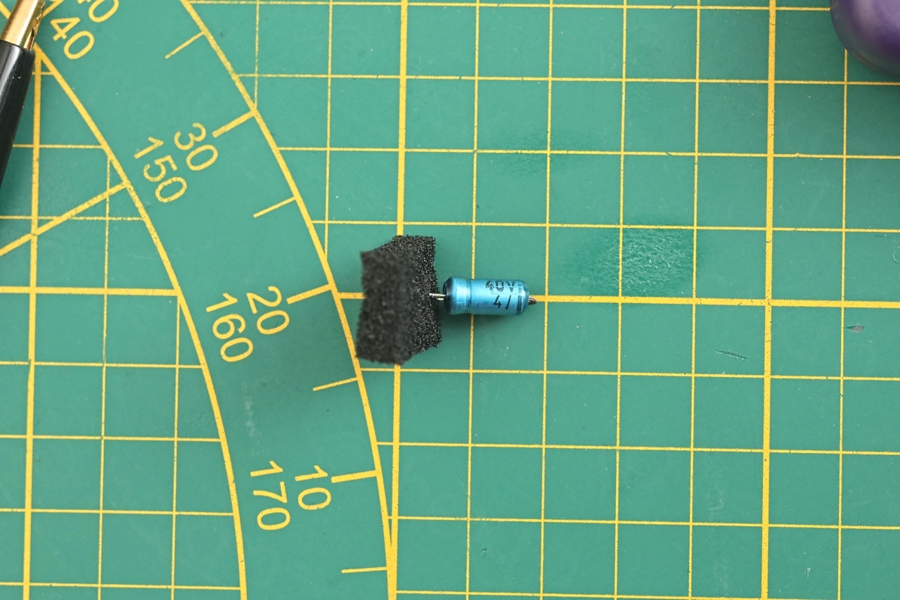
While having the capacitor out working on its trace, I decided to measure it. It is a 4uF @ 40V capacitor which measures 5.4uF and has a little higher ESR.
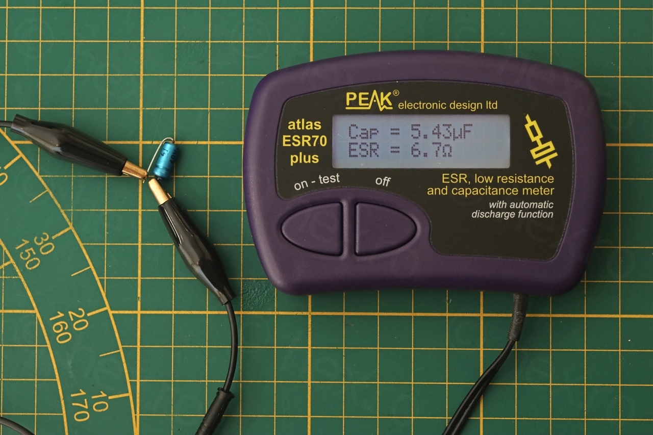
I have also paralleled a new capacitor across the existing ones without any audible improvements. Thus, I decided to not recap the radio and keep the original look.
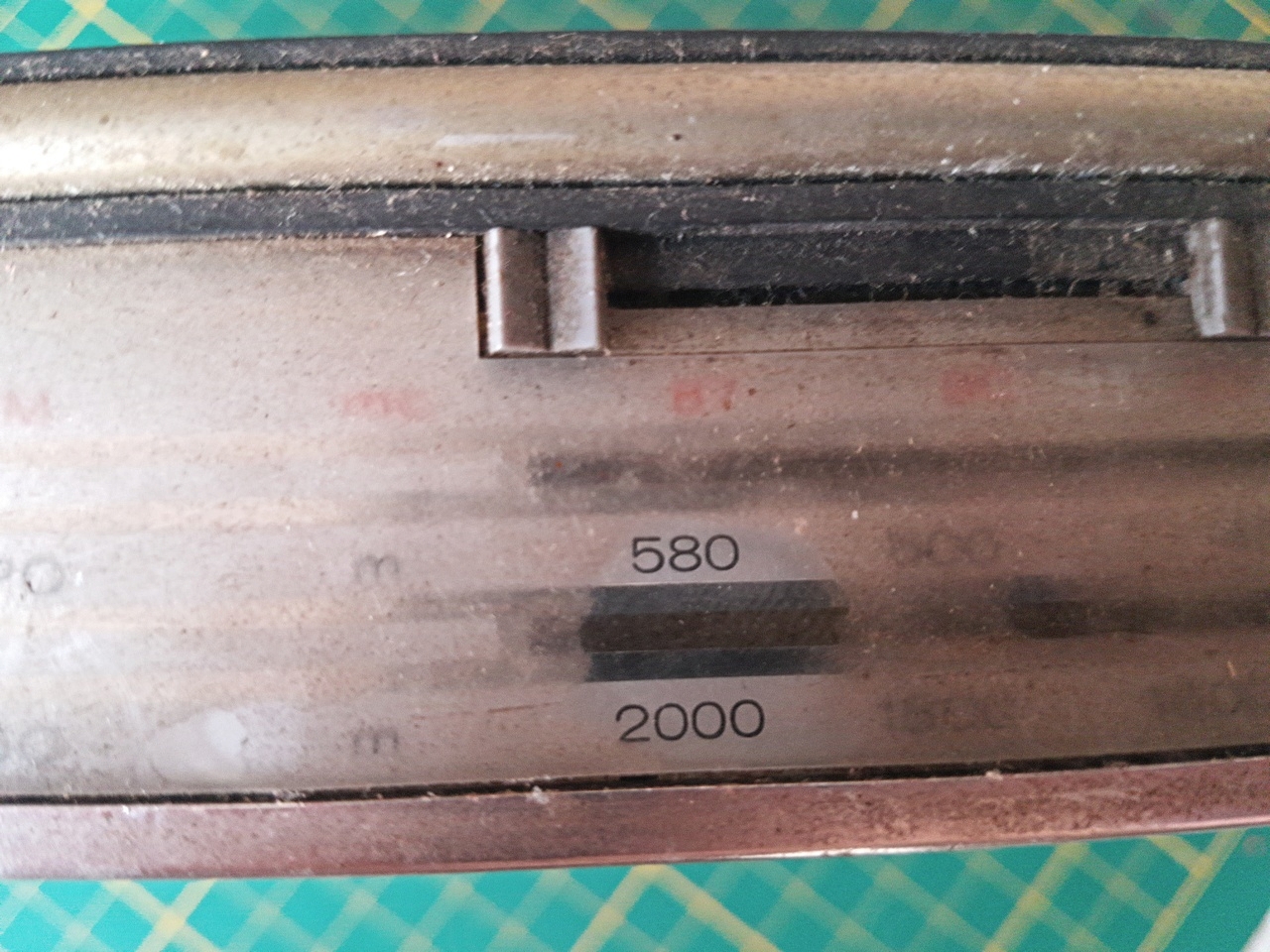
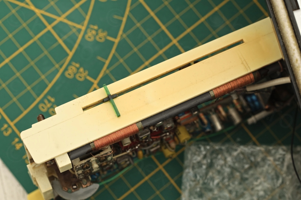
Realigning the FM dial scale
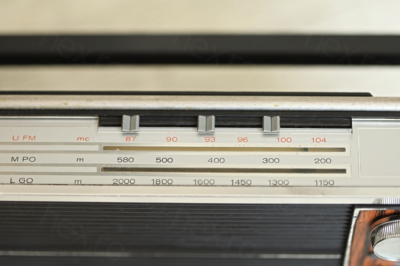
As the restoration was getting closer to being finished, I realized that the FM scale was shifted with 1MHz (meaning, a radio station emitting on 89MHz for example, will be shown by Radio as being emitted on 90MHz). Few adjustments later (C439d, C439b) and the FM scale was dialed into a much better position. The MW/LW was spot on, so this was just an FM scale issue:
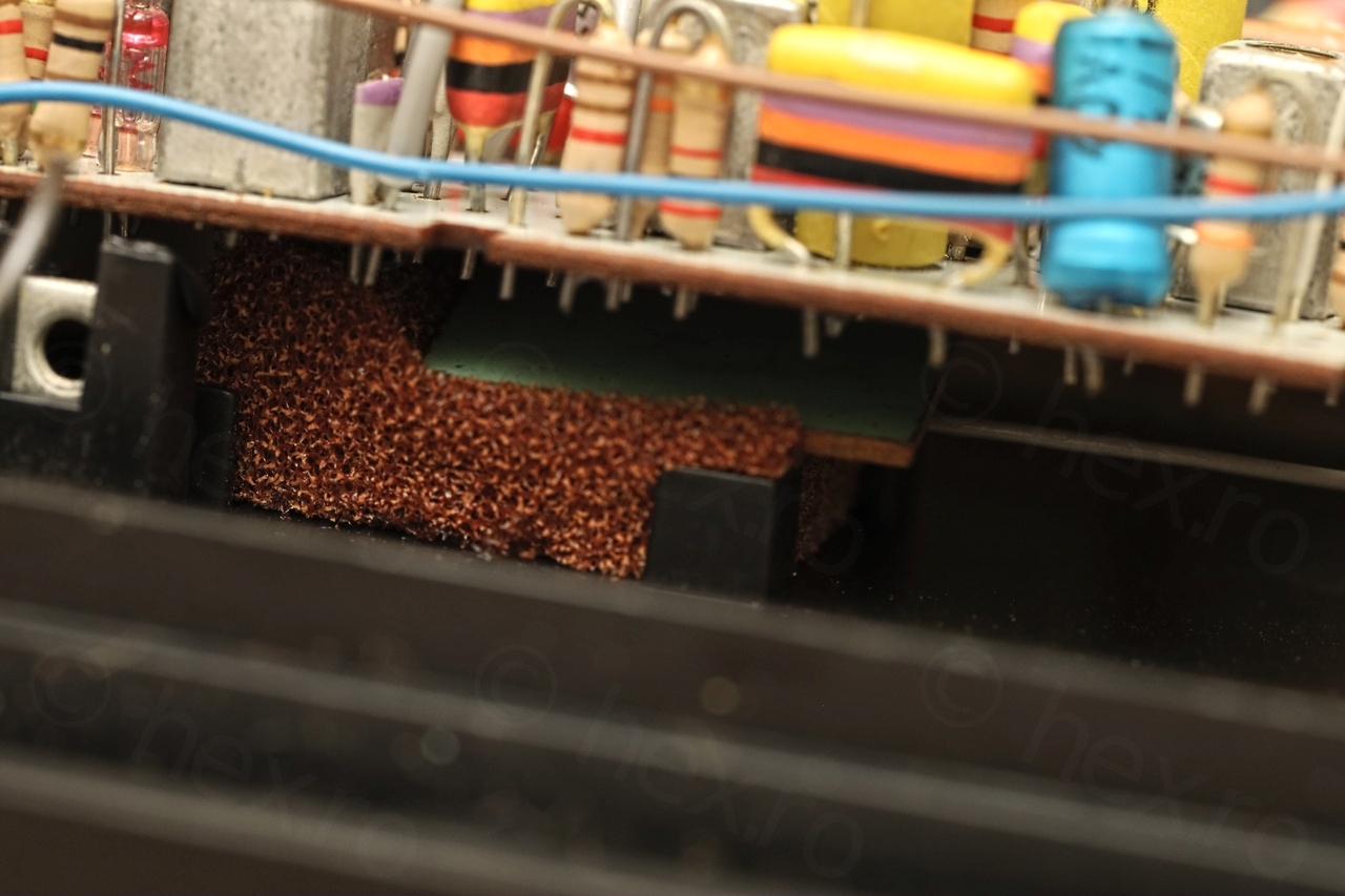
Replacing crumbling foam

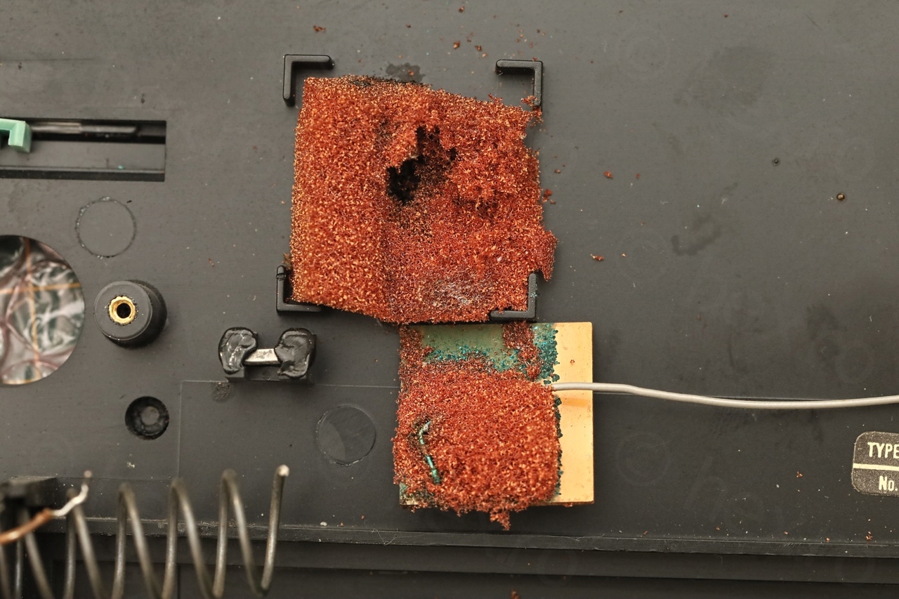
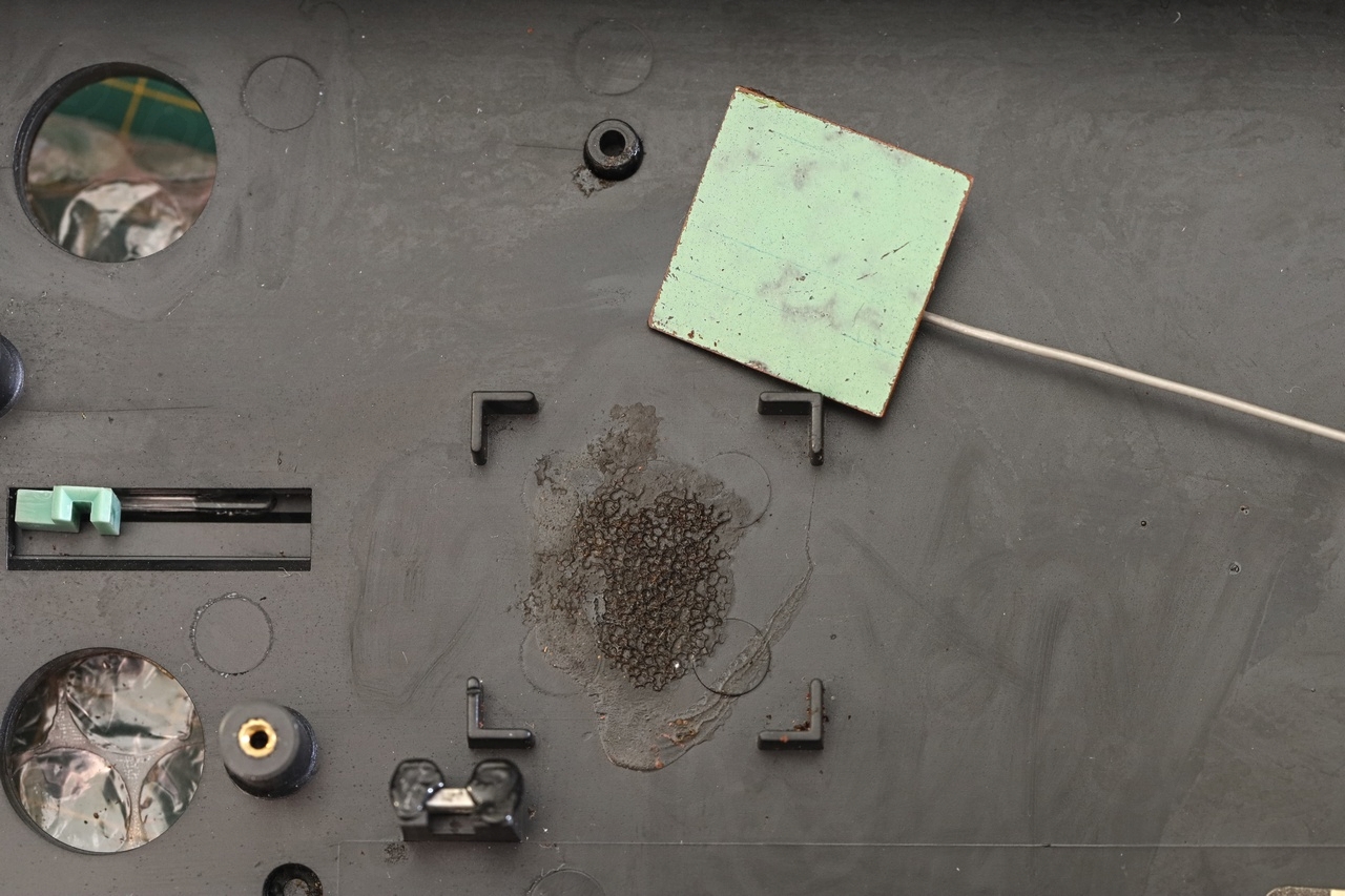
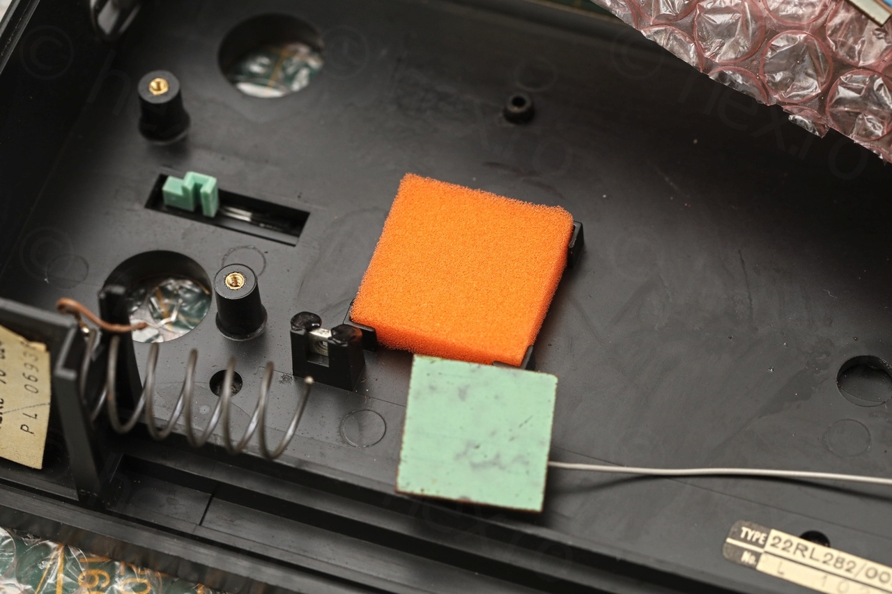
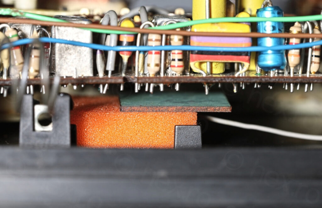
It seems the designers of the radio tried to shield some IF cans by having a ground connected plate hovering behind underneath the circuit board (around the area where some IF can are installed).
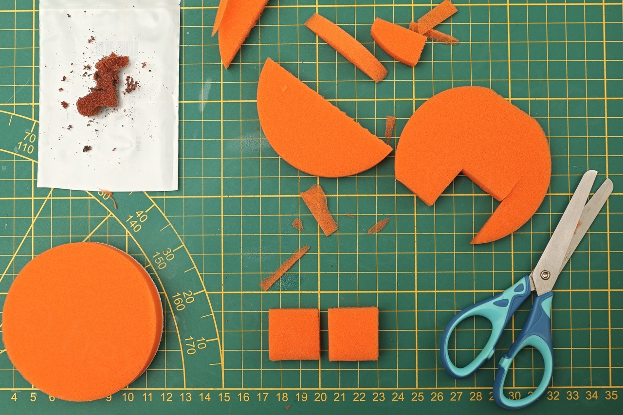
I had a hard time figuring out how to replace foam while preserving the original look and feel. I couldn’t find any brown foam that I could buy. Thus, after looking long for a suitable replacement, I ended up ordering some sponges that are made for polishing / waxing the car. There was one only with a reddish color, few more with Orange. Went with Orange – in case mistakes while cutting first one – at least there are some spares.
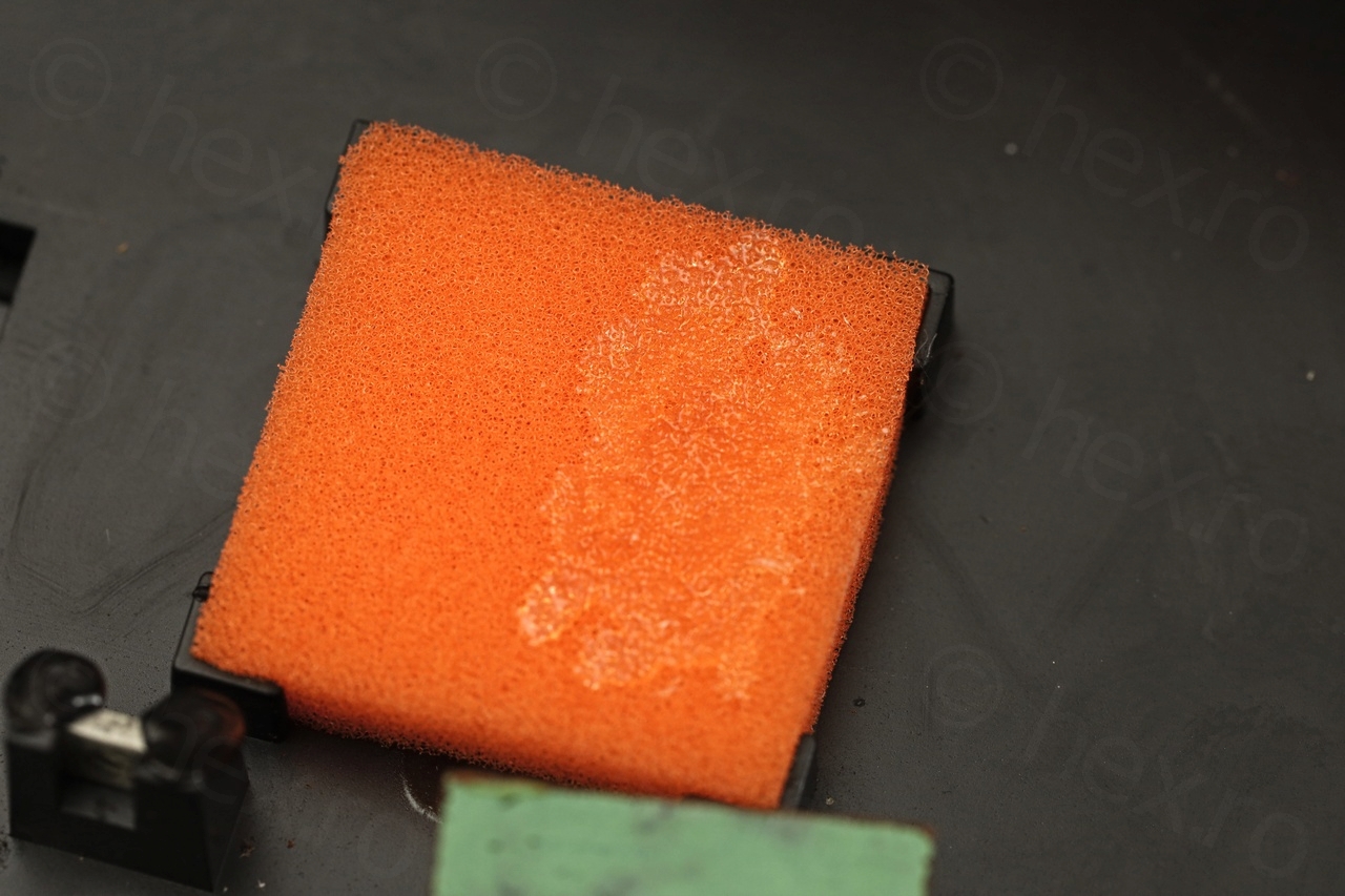
Cut a slice using the electric knife – and then finished up with scissors:

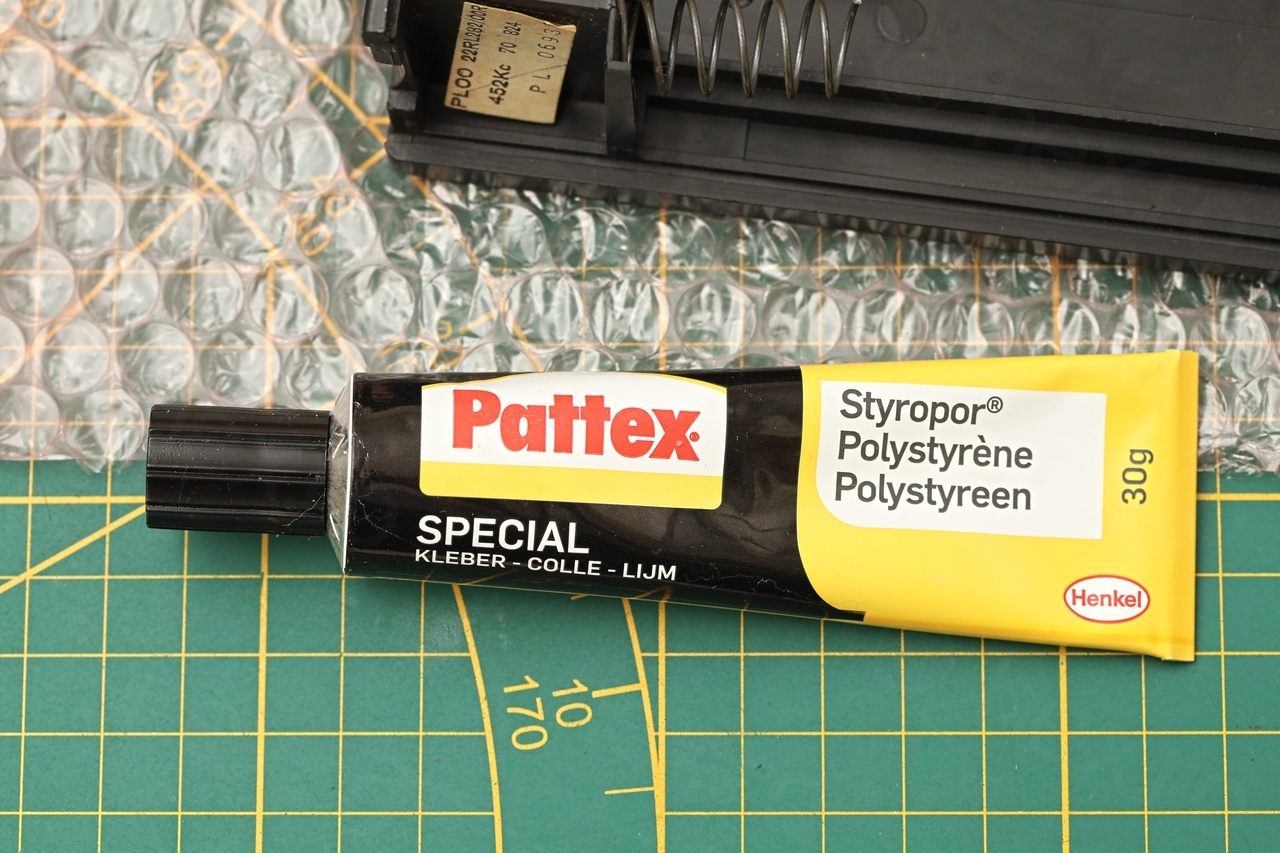
Then I cleaned the existing one and used a Polystyrene glue to attach the new foam to the case, as well as to attach the shielding plate to the foam pad itself:
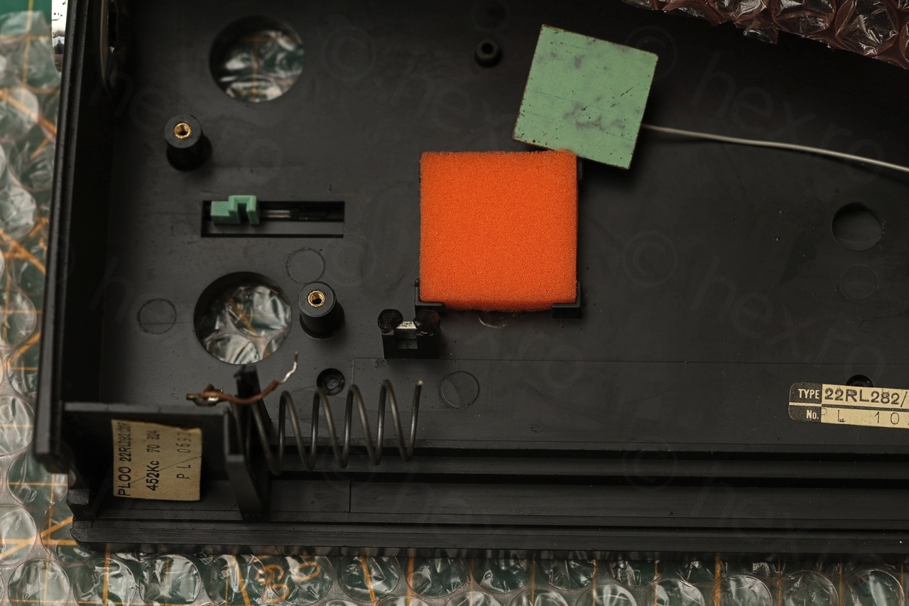

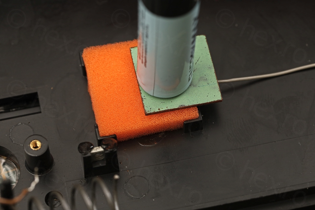
Result looks good:
Cleaning Corrosion / Rust
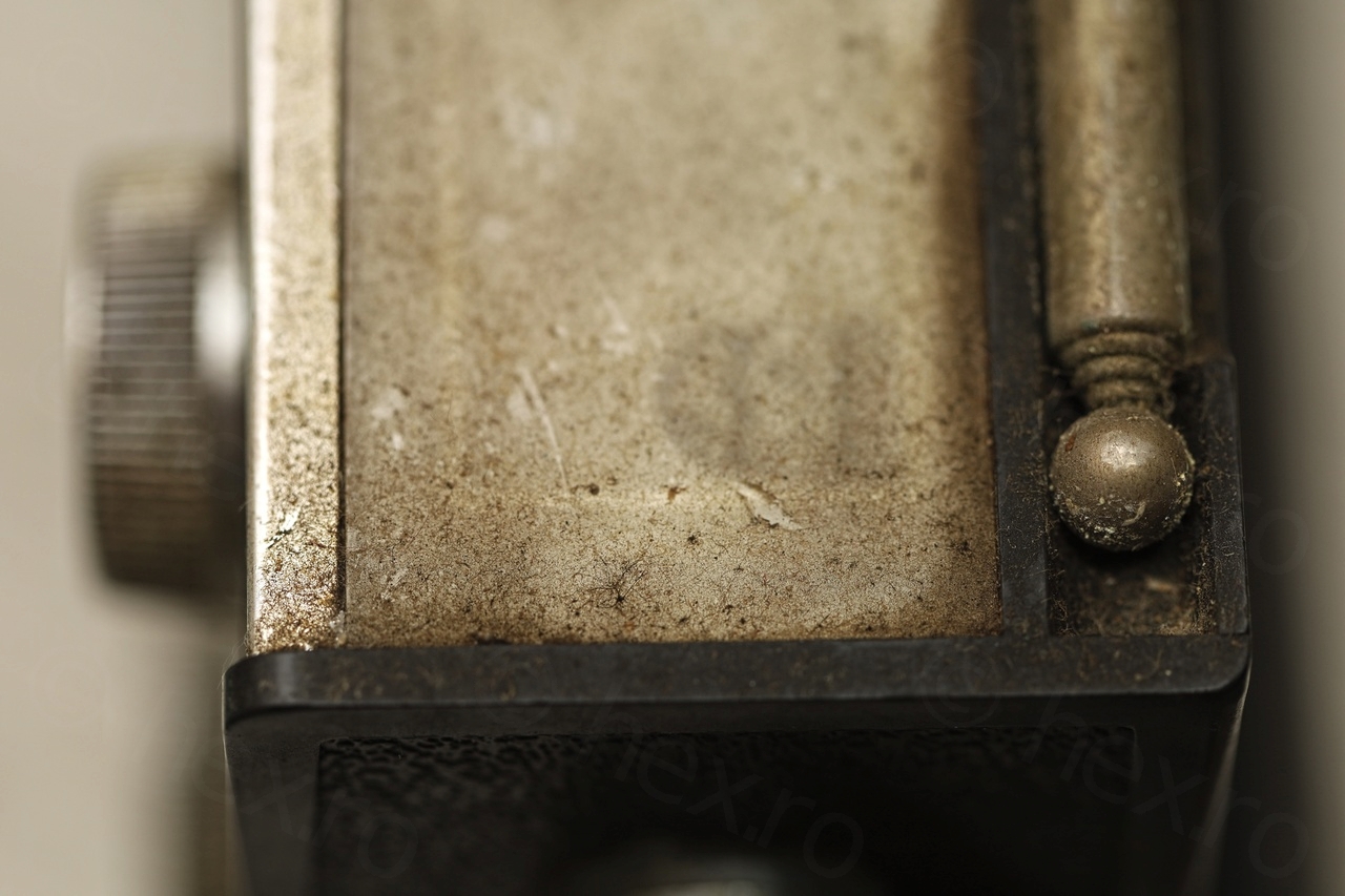
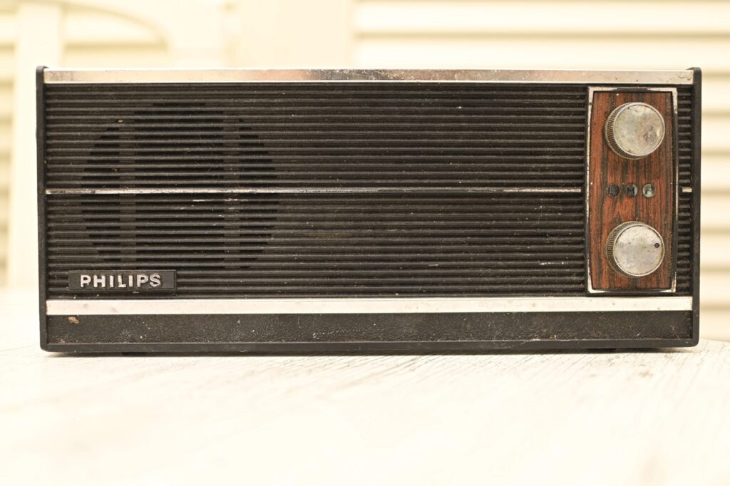
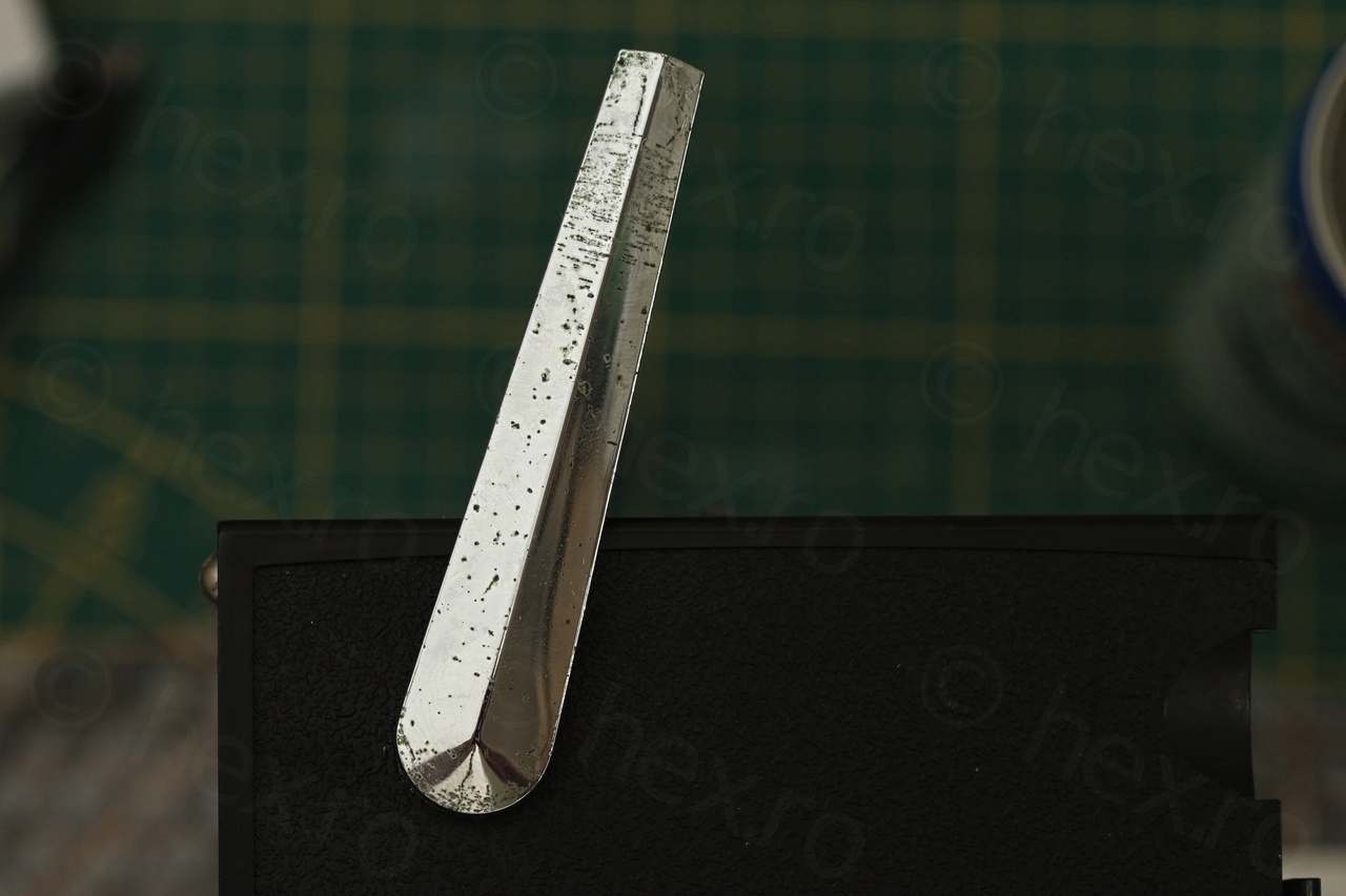
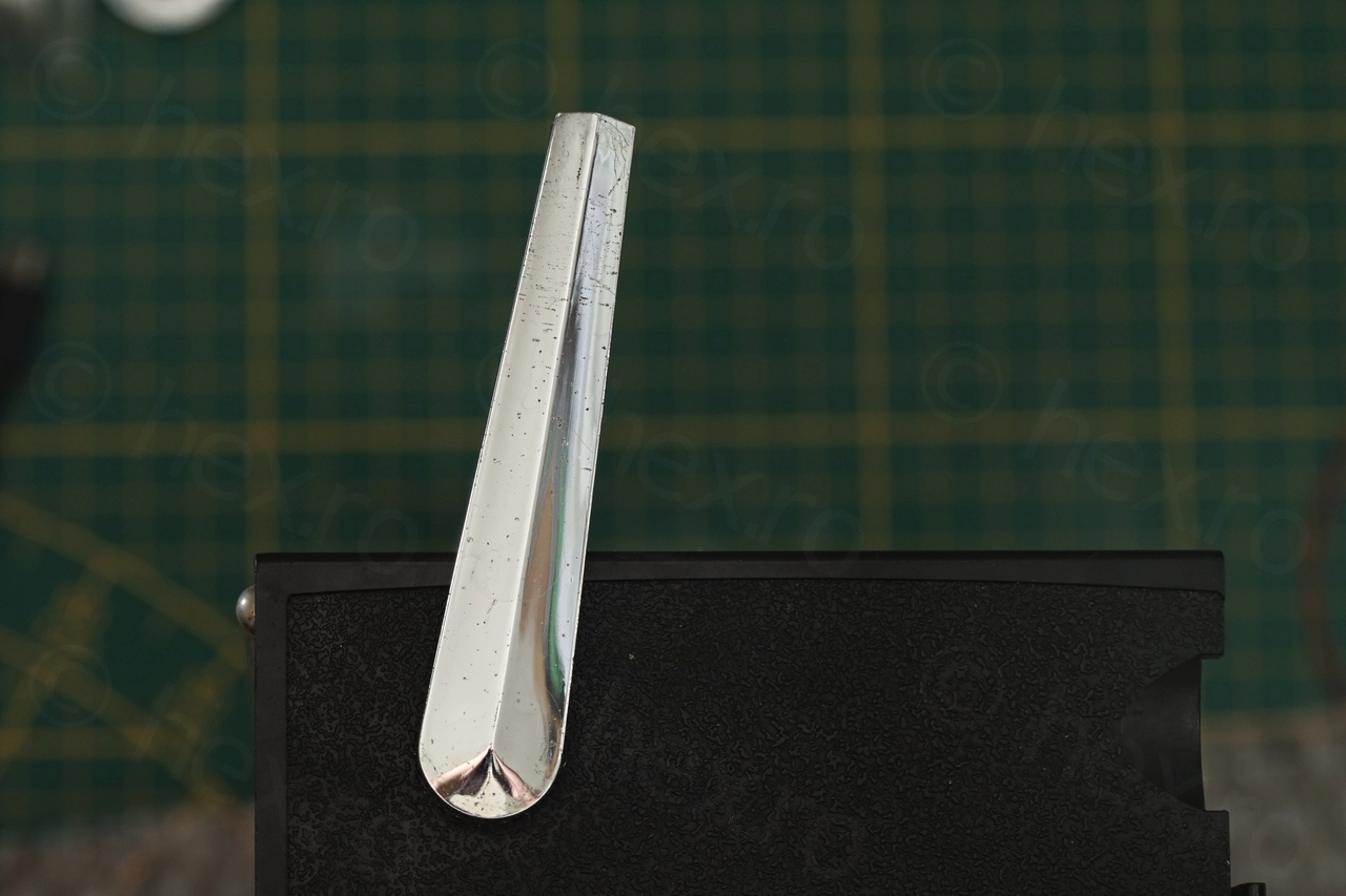
The handle of the radio looked corroded and I decided to give it a go to clean it up using Contact Cleaner and some pieces of paper. I hope that the oil component inside the Contact Cleaner will help prevent more corrosion from appearing again.
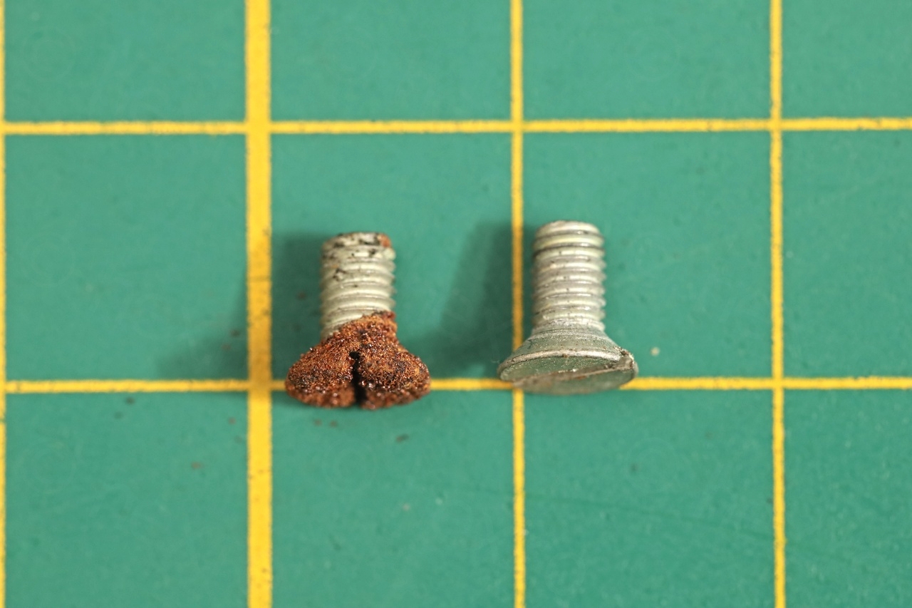
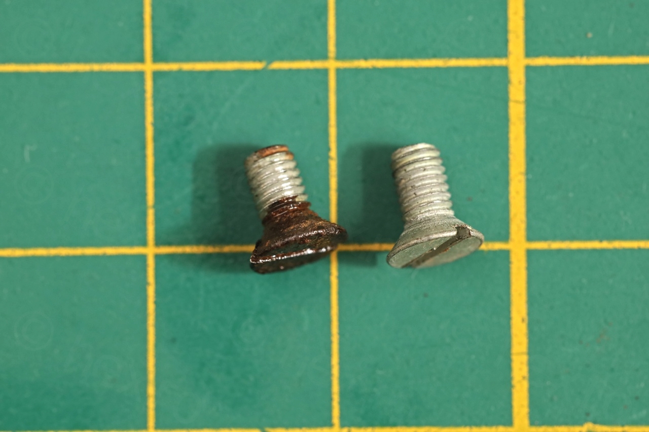
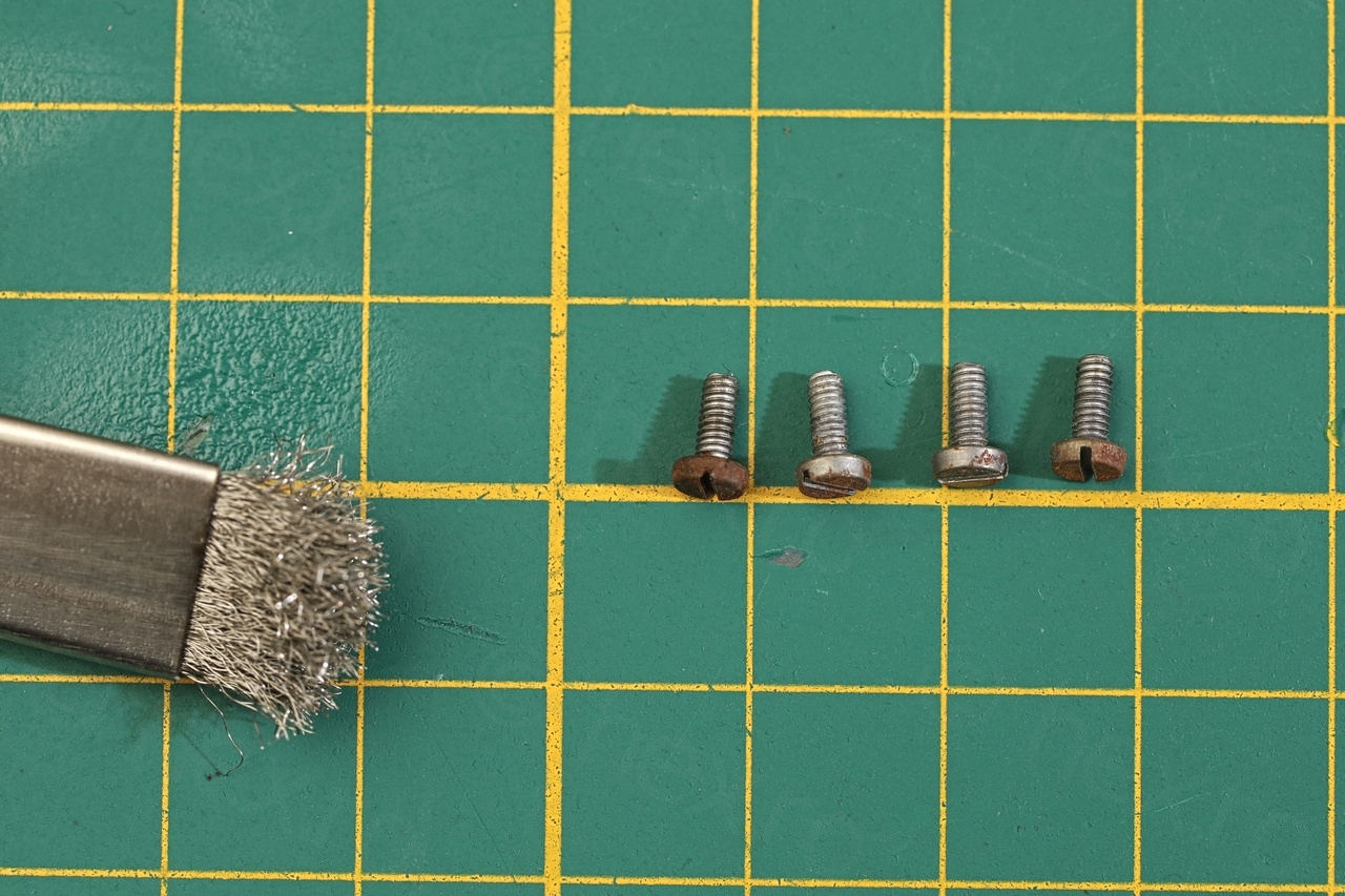
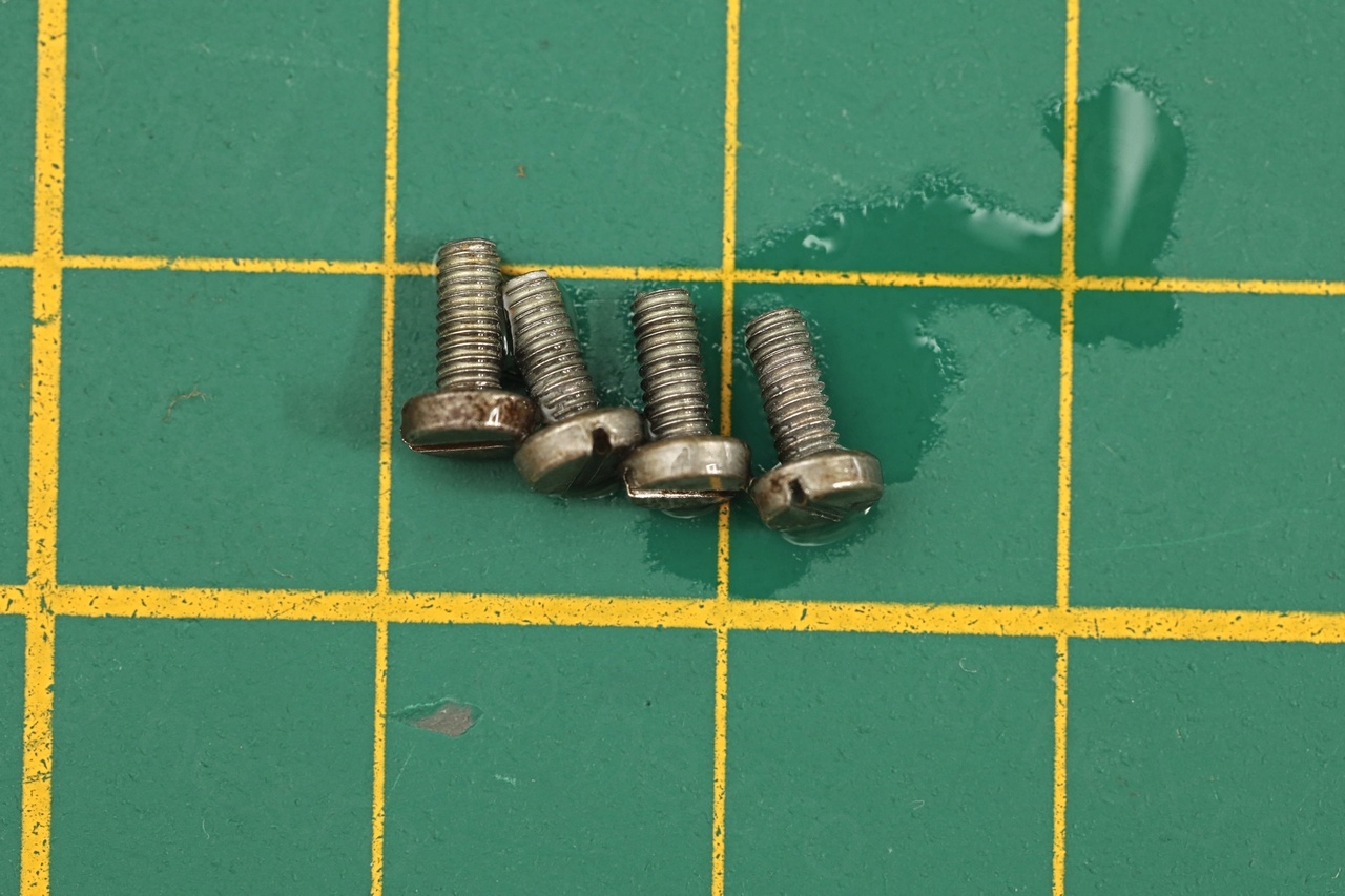
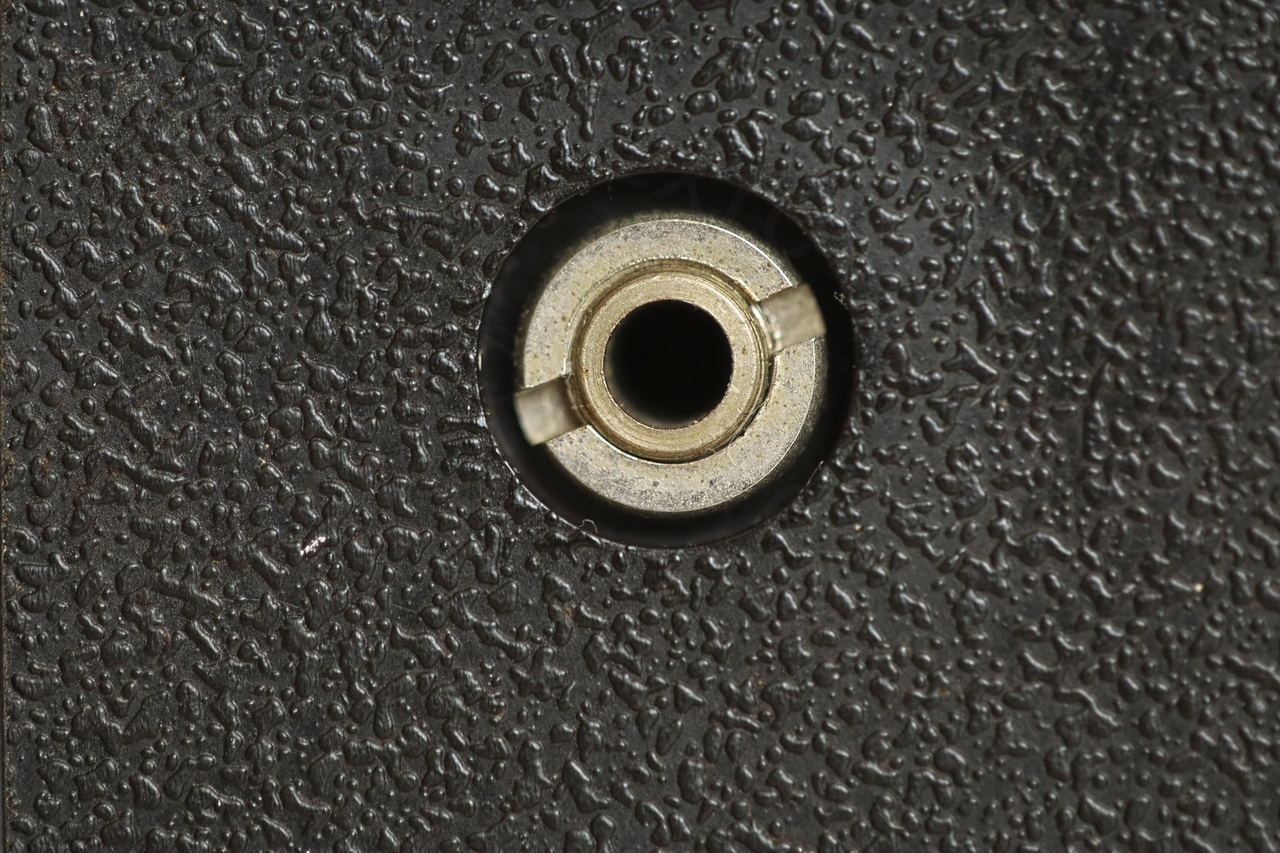
The screws as well as the nut from the earphone were cleaned with a thin steel brush:

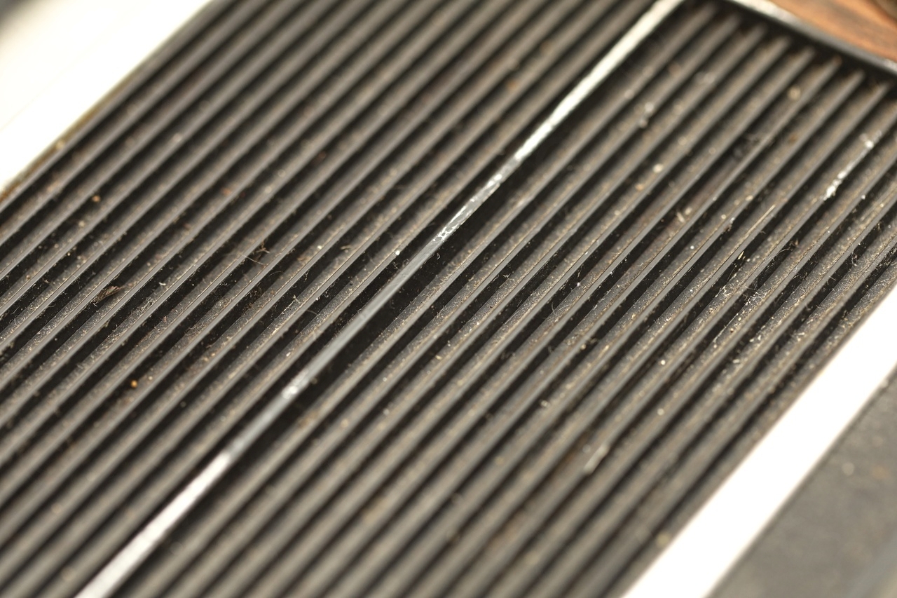
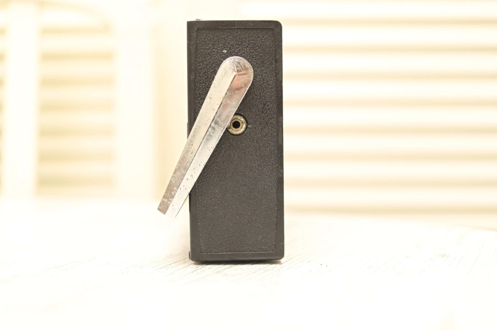
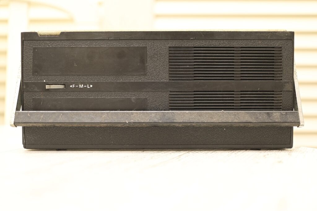
Gluing the anti-dust filter / fabric on the back case
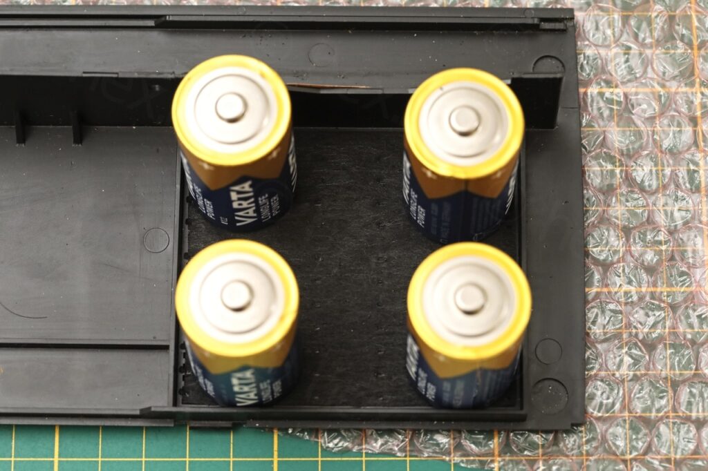
One more thing that fell was the dust filter installed on the back case. Decided to use some tissue glue to attach it back and used some C batteries to keep it pressed while the glue hardens:
Putting it all back together
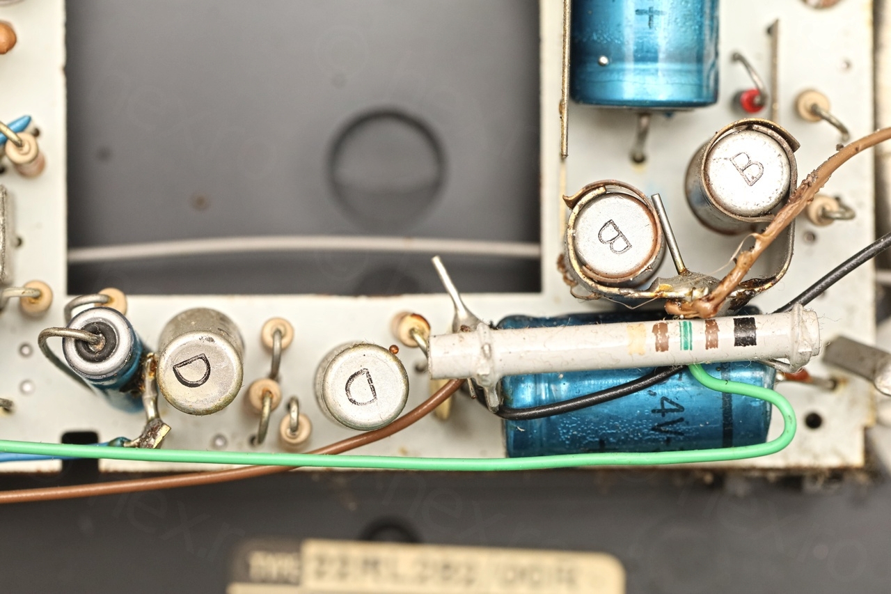
After cleaning it thoroughly – and getting it ready to reassemble, I left it running 1 hour so that I could see if anything gets hot:
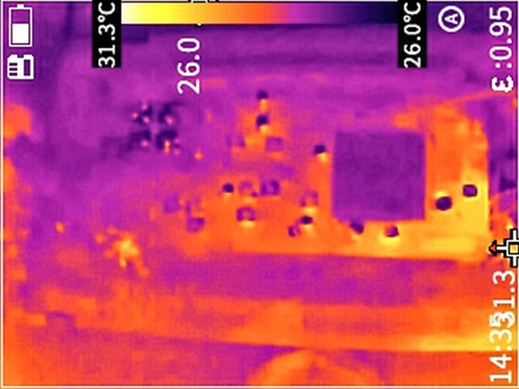
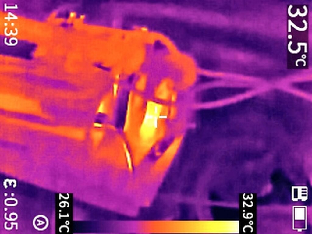
This resistor is the dropper resistor for the GR413 / BA114 voltage stabilizing diode – having it slightly warm is OK.
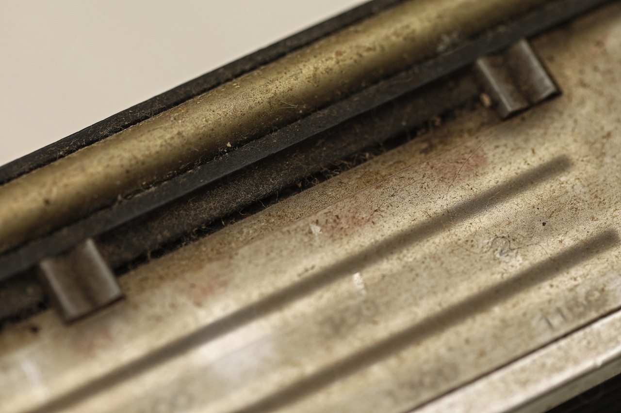
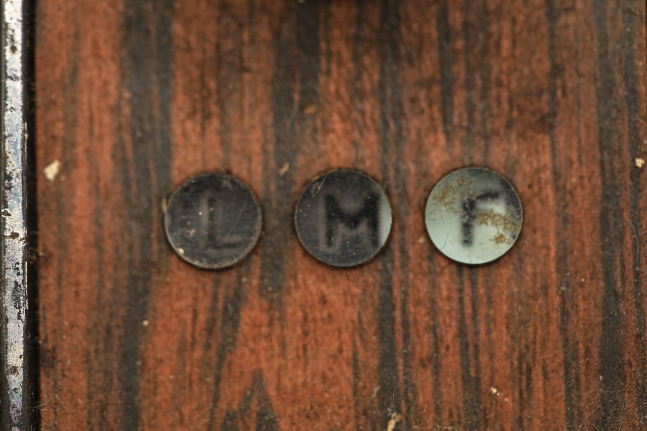
I decided to reassemble the radio. Liked how back in the days they were using some gray sliders as bookmarks for favorite stations.

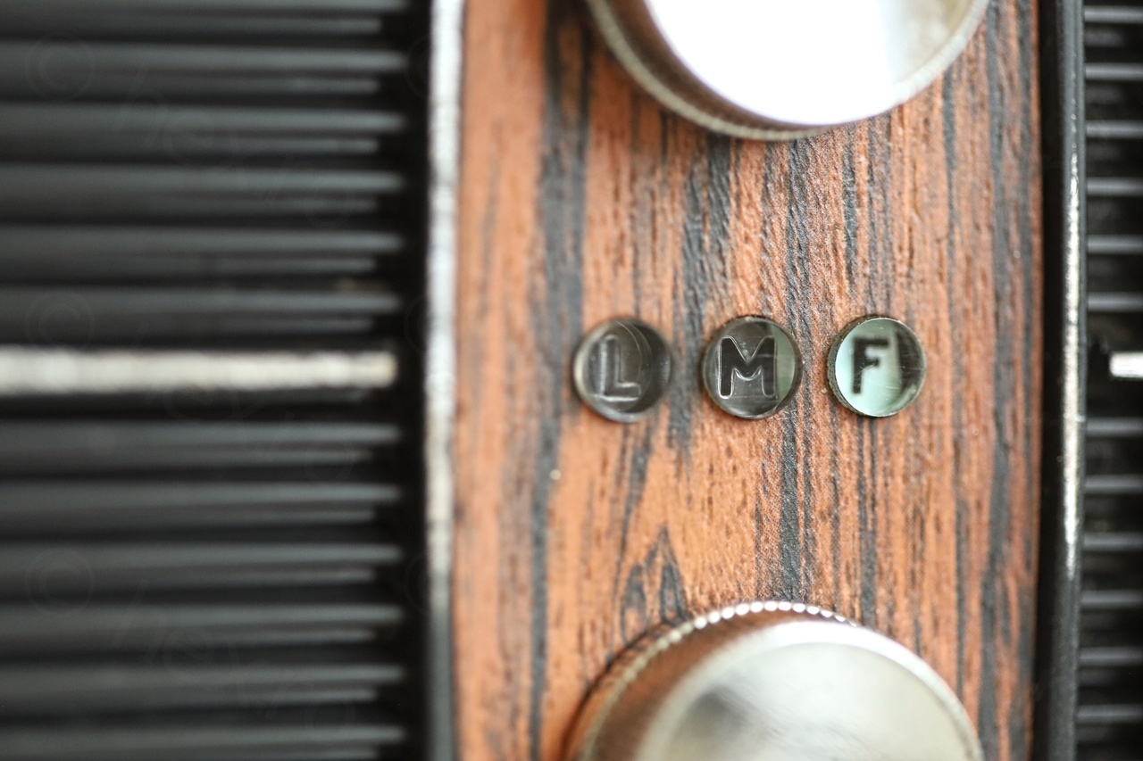

Of course, part of the cleaning was also to clean / lube the band switch, oil the button and the mechanical band indicator that is moved by the band switch.
Only drawback is that Philips radios of this era only go up to 104MHz which was the FM limit back then in Europe. Since some of my favorite radio posts are above 104MHz it means I won’t be using this one much.
Before I forget, the final test video:
marko
About those round buttons, how exactly were the fastned originally? I have another Philips radio I need to take to pieces but I’m not sure how those potentioneter knobs are fastened. Can you just pull out these or are they glued originally?
viulian
They weren’t glued on this one – I was just able to slide the knobs out.