


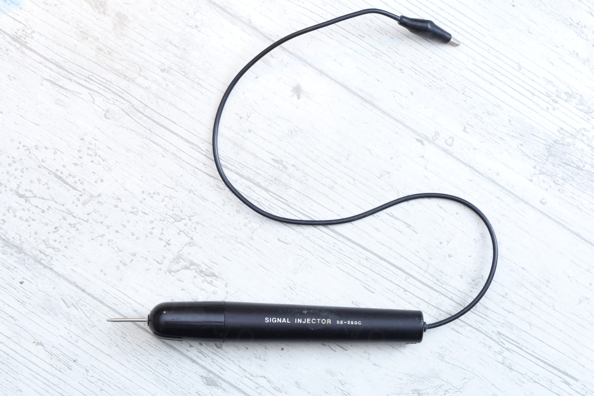
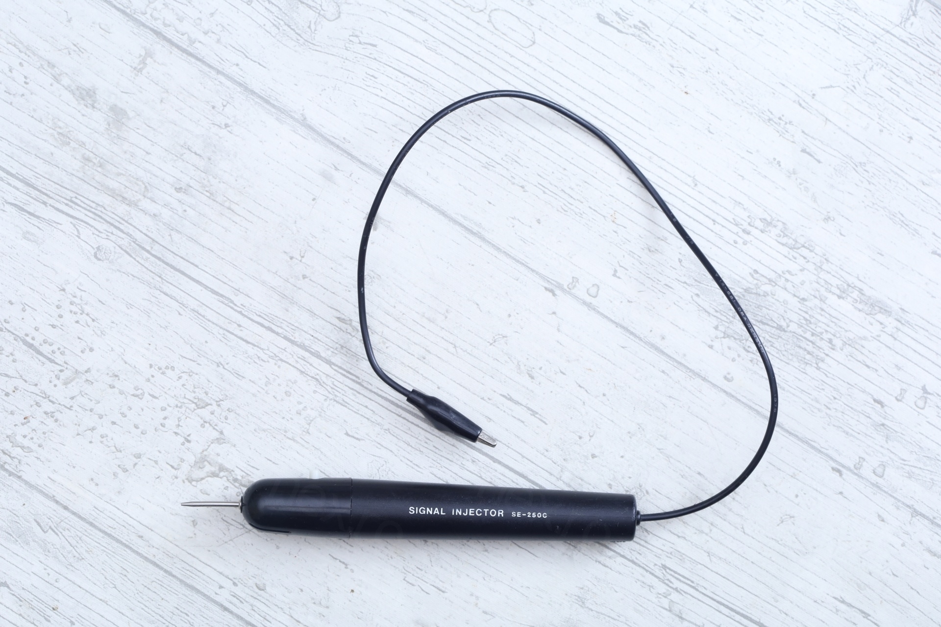
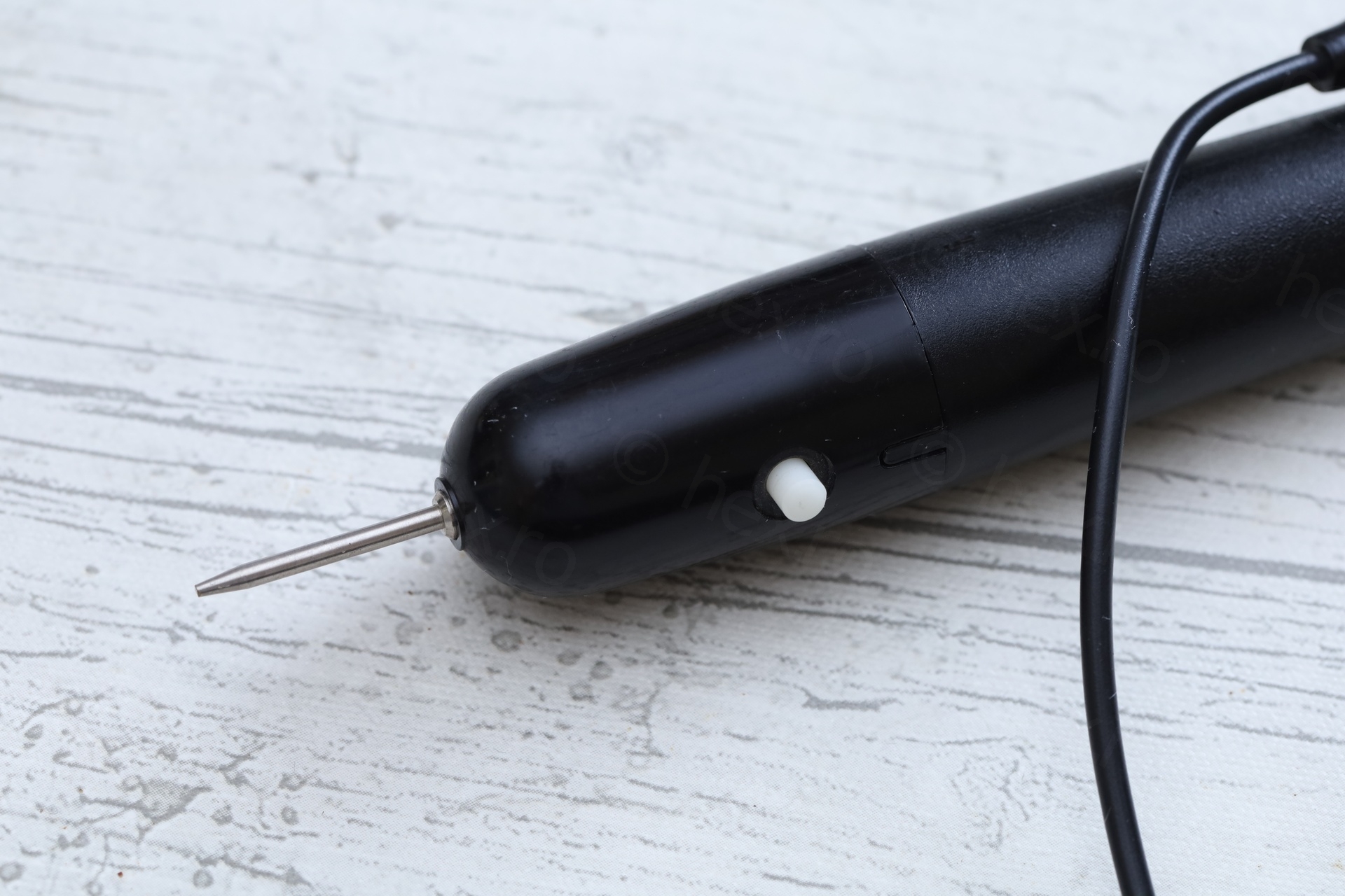
Found this old looking signal injector at a flea market and decided to buy it. Trips to flea markets are mostly boring. Many clothes / kitchen / toys and very few actual things that interest me, like old electronics.
Table of Contents
Overview
When I saw this device, I had to buy it. I do have others more advanced, there wasn’t really a need. Just to reward myself for finding it by buying it.
Opening it up
Opening it up is hard. I had to force push the cap (that is holding the tip) to one side with about 1-2mm, then do the opposite movement while making sure it is not slipping back. Difficulty is that the fit is very very tight and it could crack at any moment.
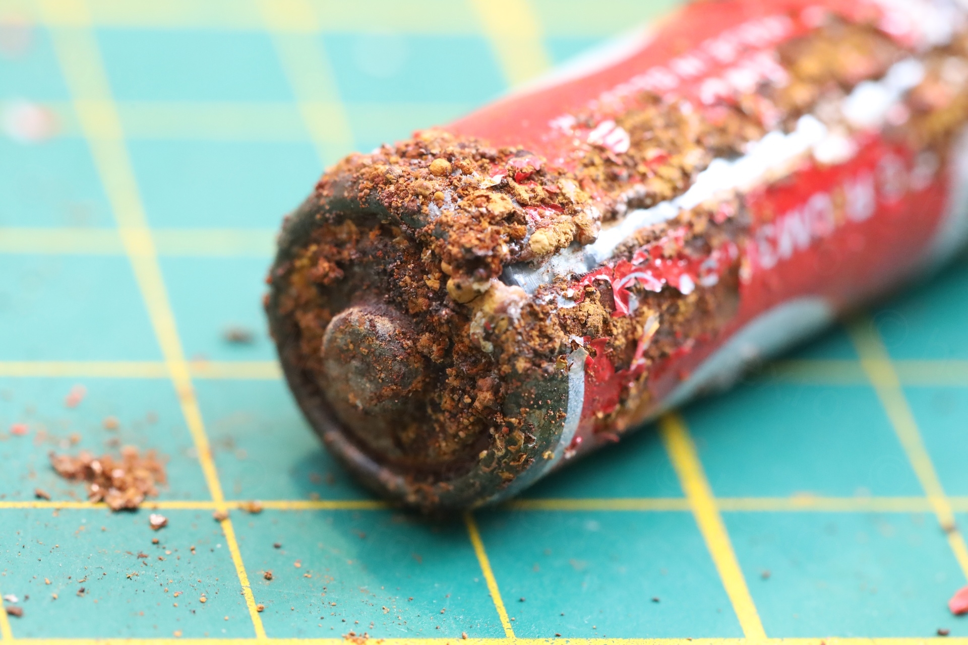
Found one of the worst corroded batteries I ever saw:
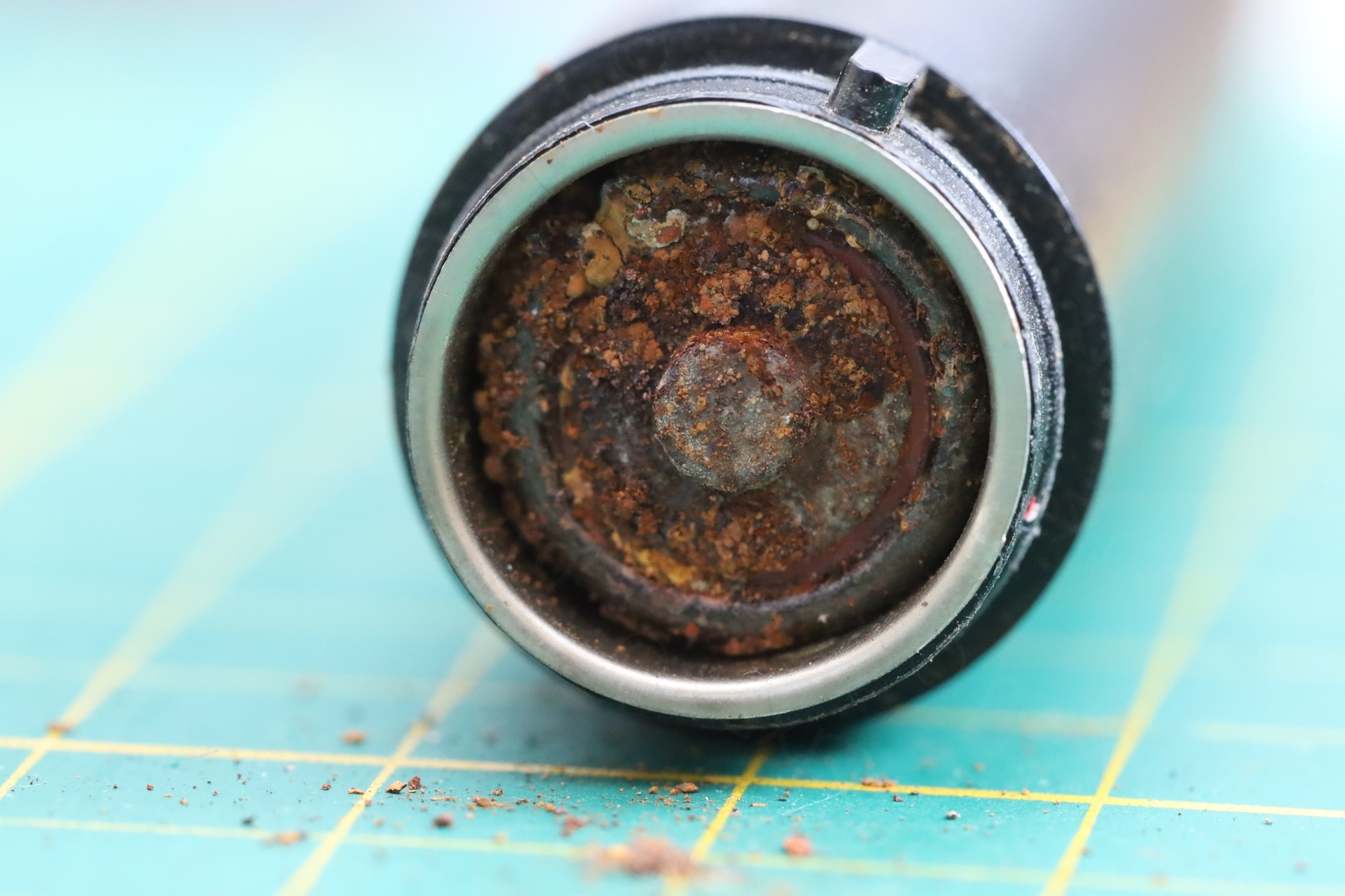
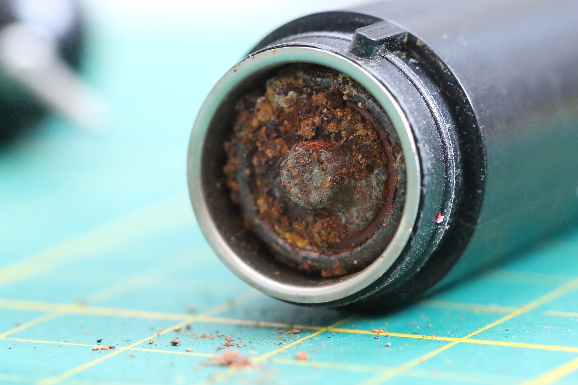

Surprisingly, no other parts were affected by corrosion. I drenched the battery container body with contact cleaner, wrapped some paper around a long screwdriver and wiped the insides.
The tiny circuit board didn’t seem easy to extract. It has some guides so obviously it has to come straight out. But it was not clear if the tip stays attached to it or not ? The terminal for the Battery + was soldered with a huge blob of solder. With a screwdriver wedged under the blob, I was able to slowly pry the board out. The tip stays attached (it is soldered too):


I was looking online for the schematics, but I found none.
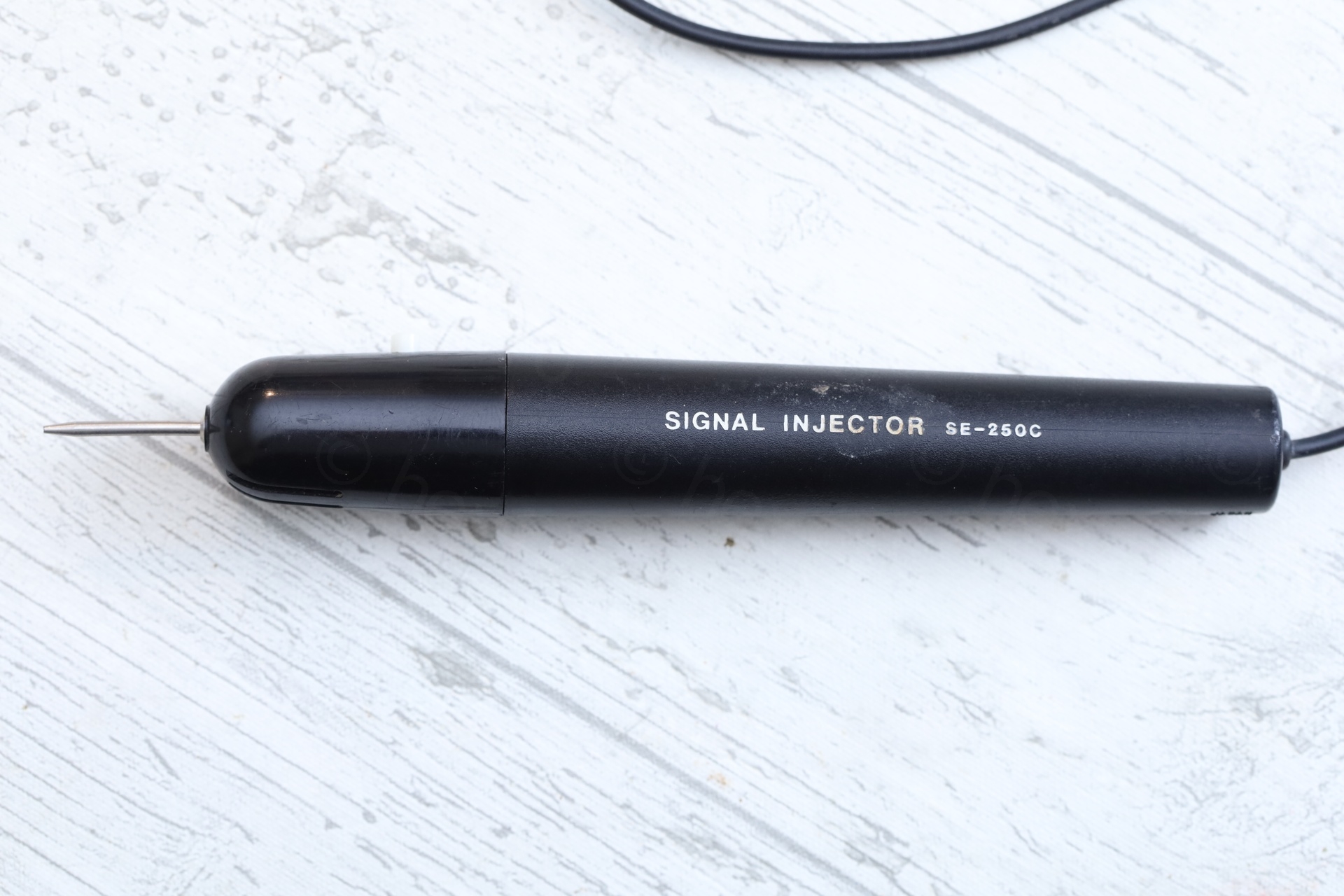
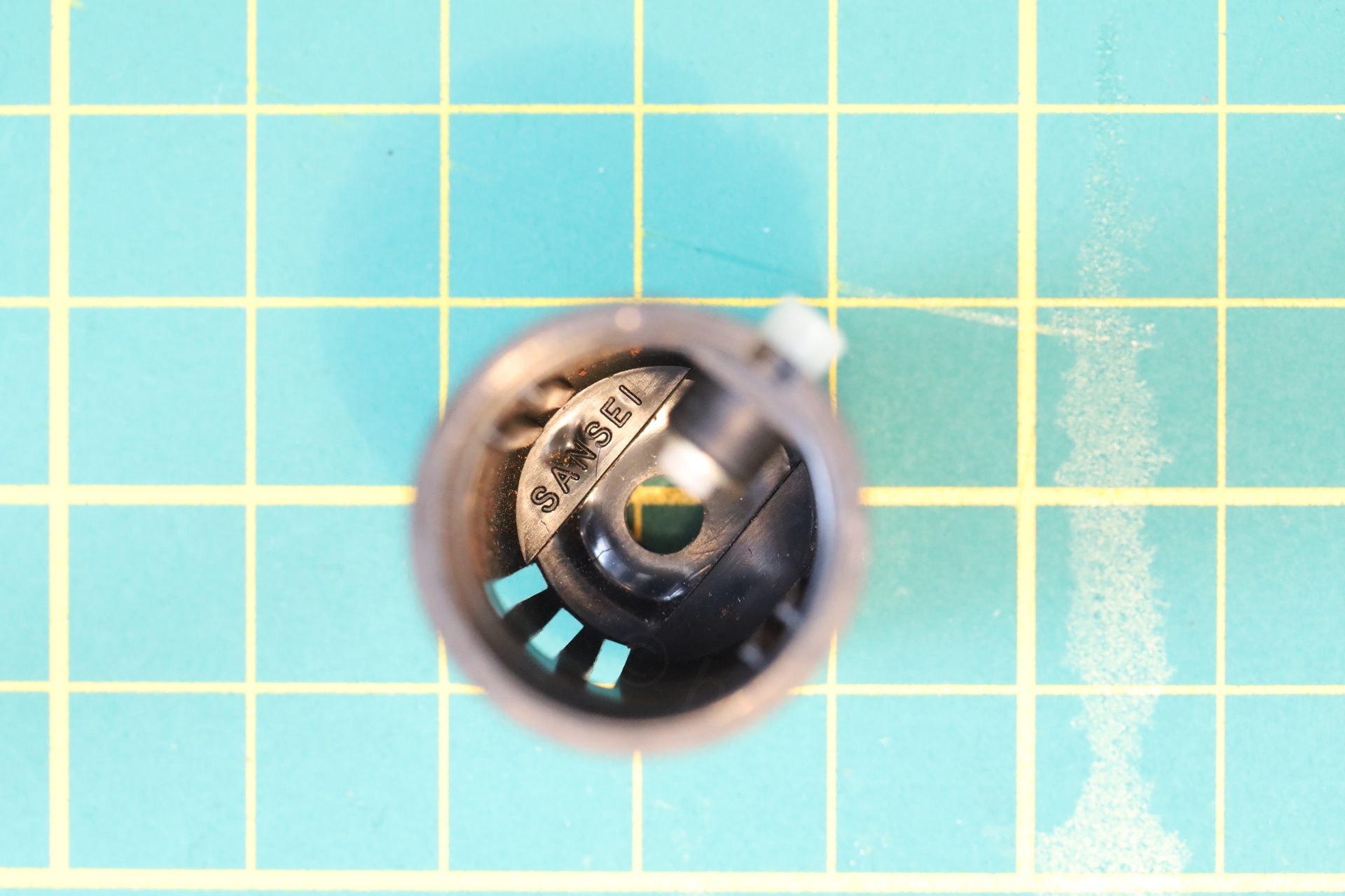
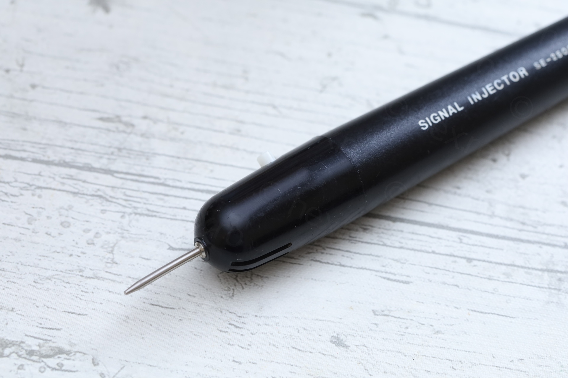
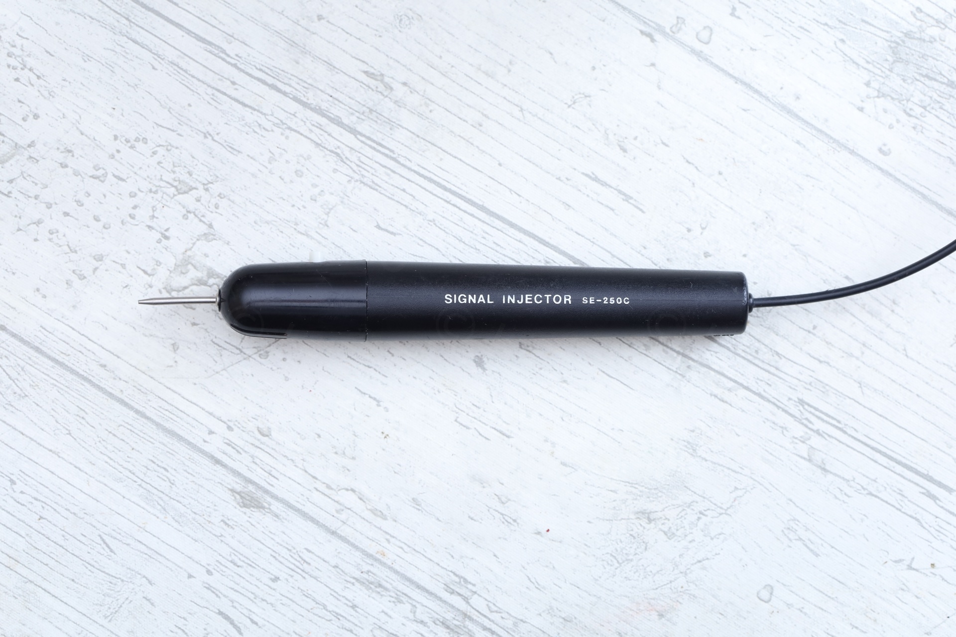
I saw this identical device on Radiomuseum website. It mentions CTR-Elektronik, Nürnberg as producer. The funny thing is that mine has the text SANSEI stamped inside the end cap holding the circuit board (and good I looked). This device seems produced by SANSEI and not CTR-Elektronik as written on RM.
Probing its Output
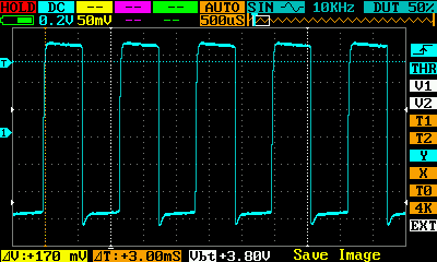
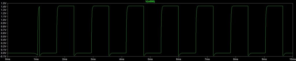
Looking at its output using a DS203 mini oscilloscope, the most important things stand out: square wave 1.4Vpp, frequency around 860Hz:


By now I had consumed the few online articles about the signal injectors – the most interesting related one was in German, found also on Radiomuseum website. It has a link to the schematics of an apparently similar named model (SE-250) and that one is based on an astable multivibrator with 2 transistors.
Schematics
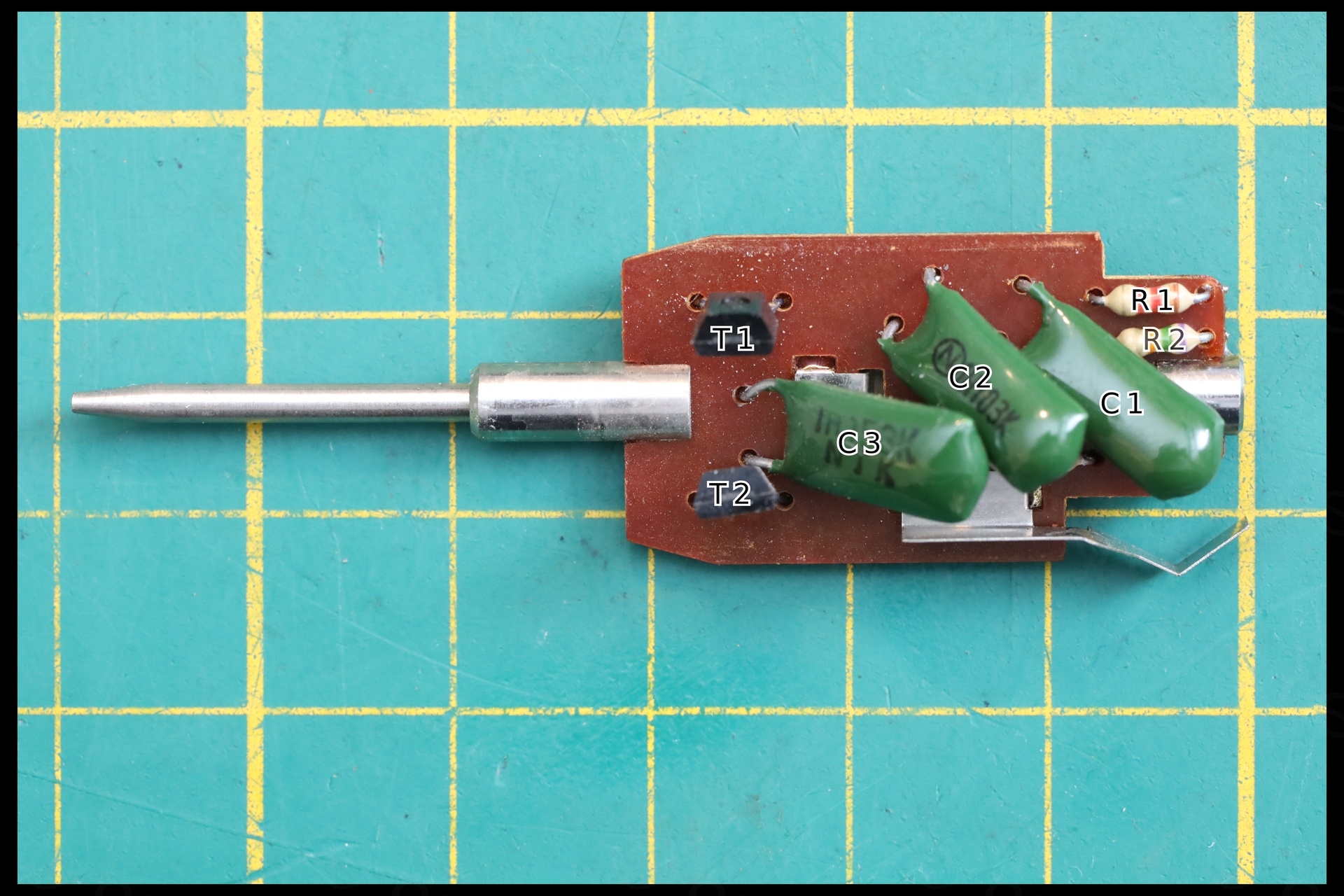
I wanted to make sure that mine is similar so I proceeded to extract the circuit diagram and values from the board. Without a schematic, I was free to number the components 🙂 as I wanted:
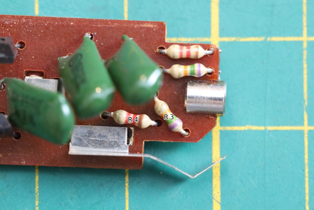
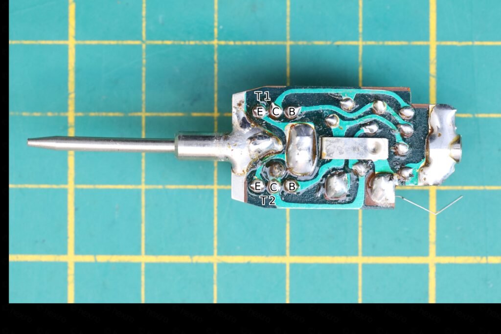

Circuit traced using GIMP, and Schematics made in LTSpice
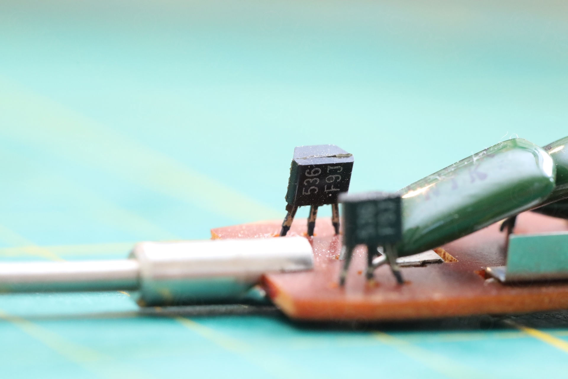
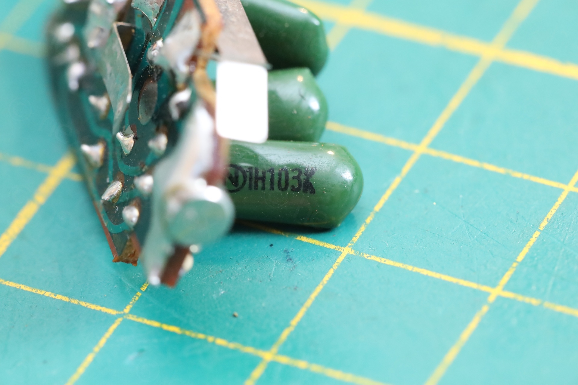
There are two identical transistors, 2SC536 (marked “536 F9J”). Three capacitors – the 15nF one is in series with the probe tip, the other two are 10nF each. 4 resistors, two of them 75KΩ and the other two 1K2. Resistors are tiny in size with 5% tolerance. In fact, I can’t tell if the tolerance line color is Gold or Gray, most likely Gold ?
The switch (and I did not find a simple switch in LTSpice) is between battery GND and the emitters of the transistors.
The simulation matches the output perfectly 🙂 using BC237B as model (I was not able to find a model for 2SC536, but web-bcs.com website lists BC237 as a substitute, and this one I found modeled).
In conclusion, a cute little device. I am tempted to 3D print a similar one, and maybe use Germanium transistors.
Steven Hurst
Hi,
Thanks for your descriptive strip down and analysis of this signal injector. Having just bought one of these off of Ebay I found it most useful when dismantling mine. Only the base of the battery was corroded and also the spring underneath, but the rest of the components were fine. At some point I will use your scope findings to compare mine to them. All in all a thumbs up from me for your efforts . Thank you
Steve …MM0ARZ ( Scotland )
Add.. Did you ascertain how old this device is ?
viulian
Thank you for your message,
I have no idea of the year. But if I had to guess, I’d say early 1980s, mainly because the green PCB reminds me a bit of Sinclair ZX80 Spectrums’ motherboards..