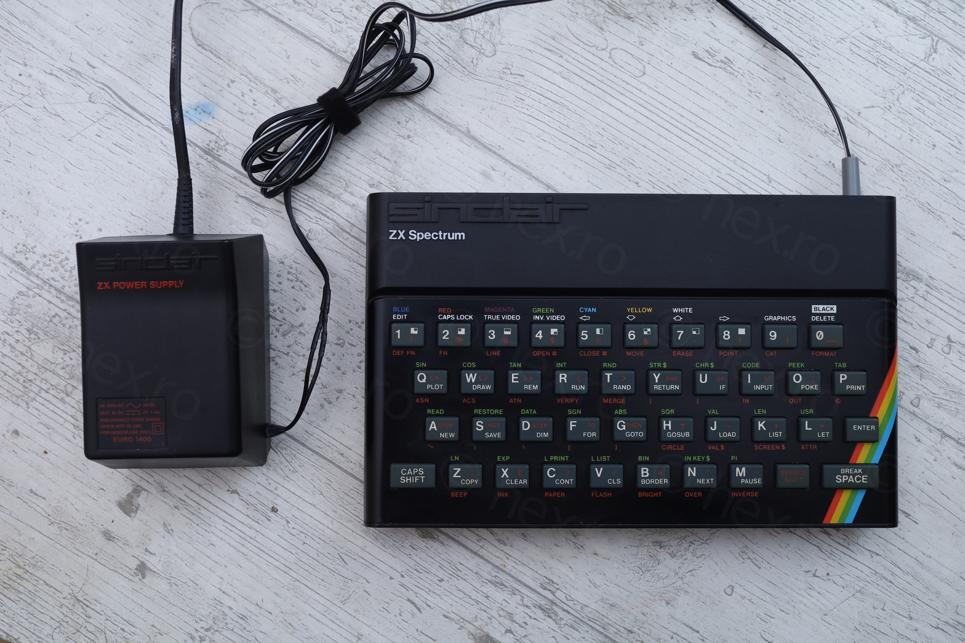
Had a hard time picking up the title for this repair. Went with the power supply as it was the most shocking, although, the computer accompanying it wasn’t so easy to understand either.
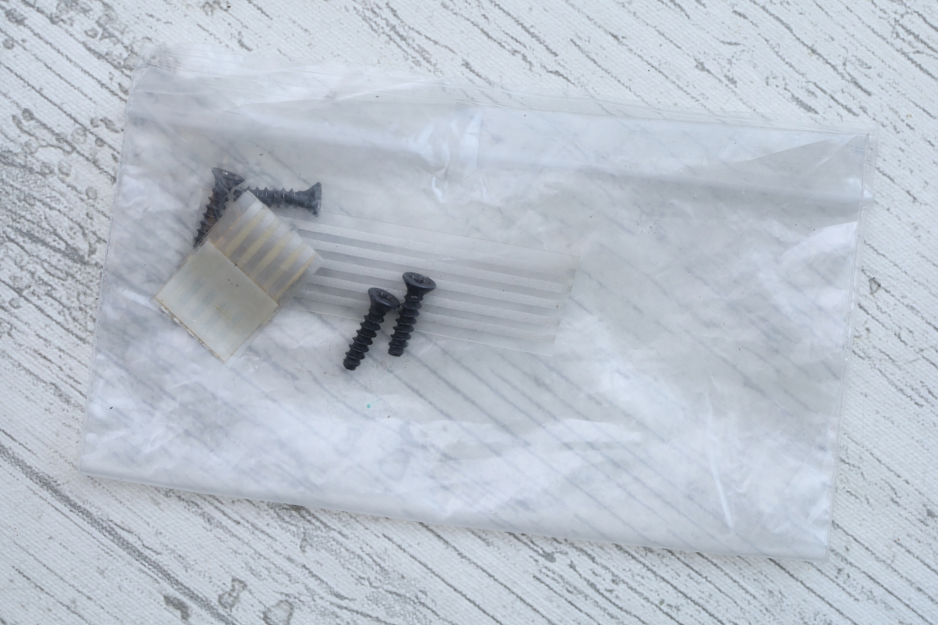
Back to this announcement I see on EBay. Seller is serious. Has hand-written notes with arrows pointing to what is broken. He packed all the parts and screws that were taken out in the attempt (he?) made to fix the computer. One last mention he makes, computer does not start with the provided power supply.
Table of Contents
- Visual checks
- Electrical checks
- Diagnosis
- Bit 1 and 4 – Upper RAM ICs
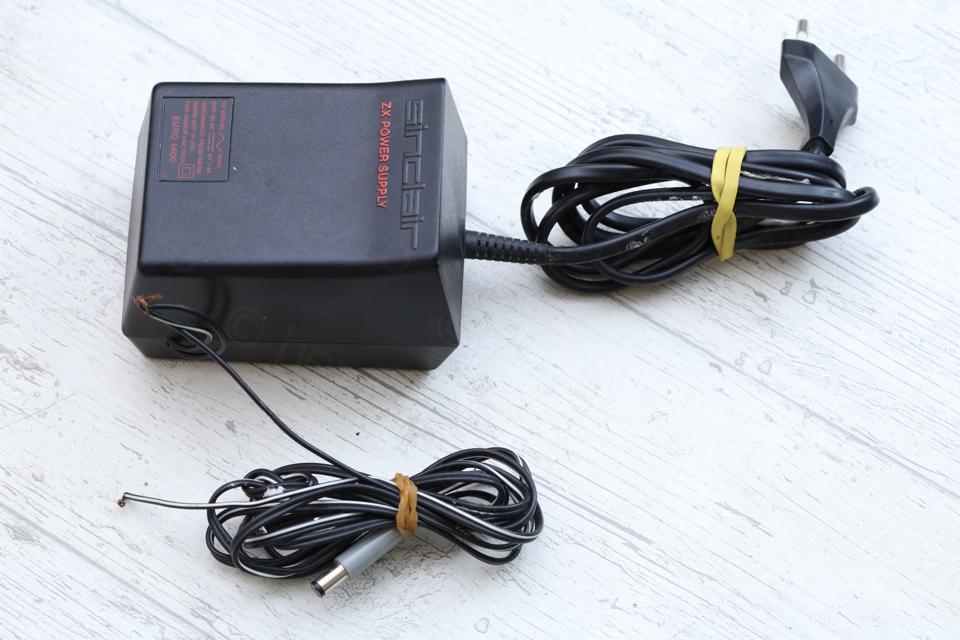
- Euro 1400 Power Supply
- Straightening the face plate
- Finishing touches
- Summary
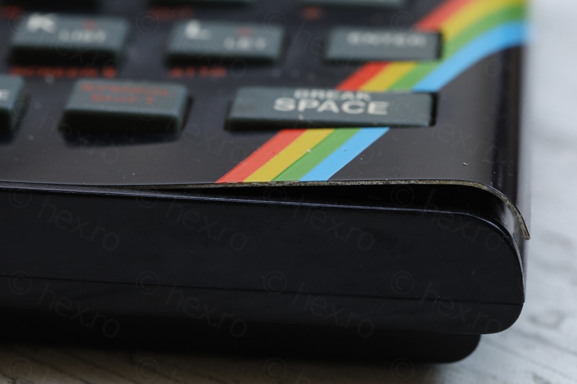
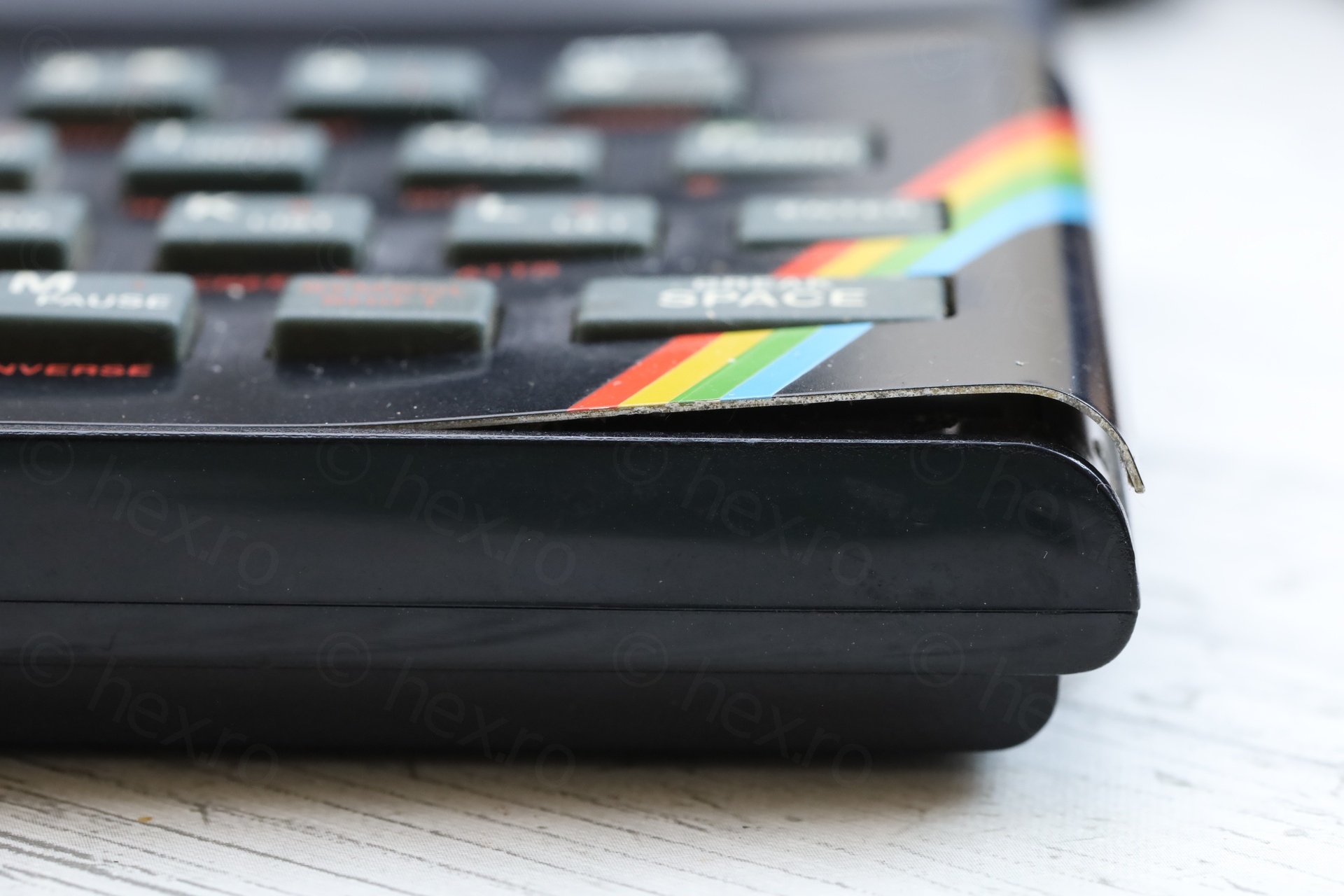
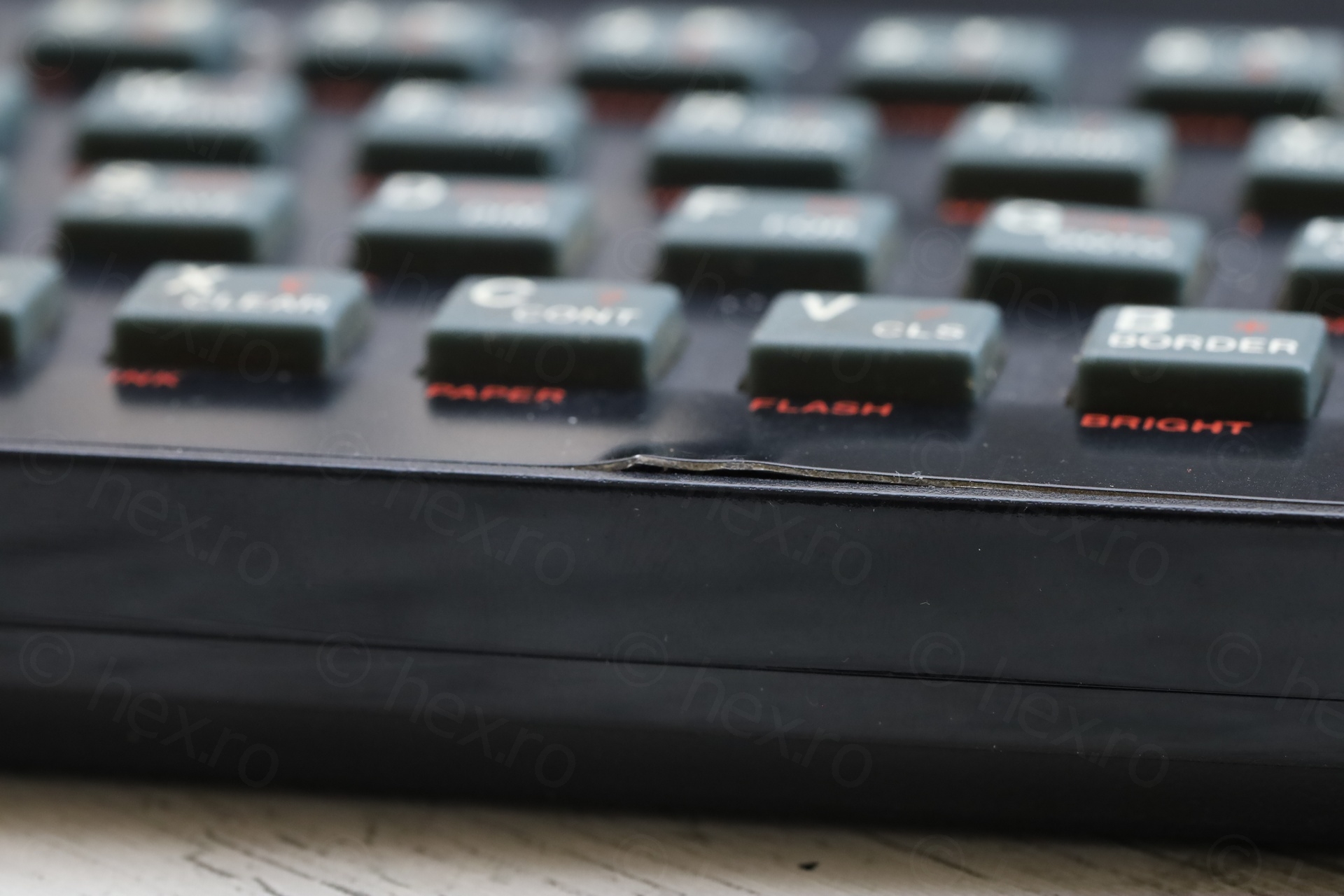
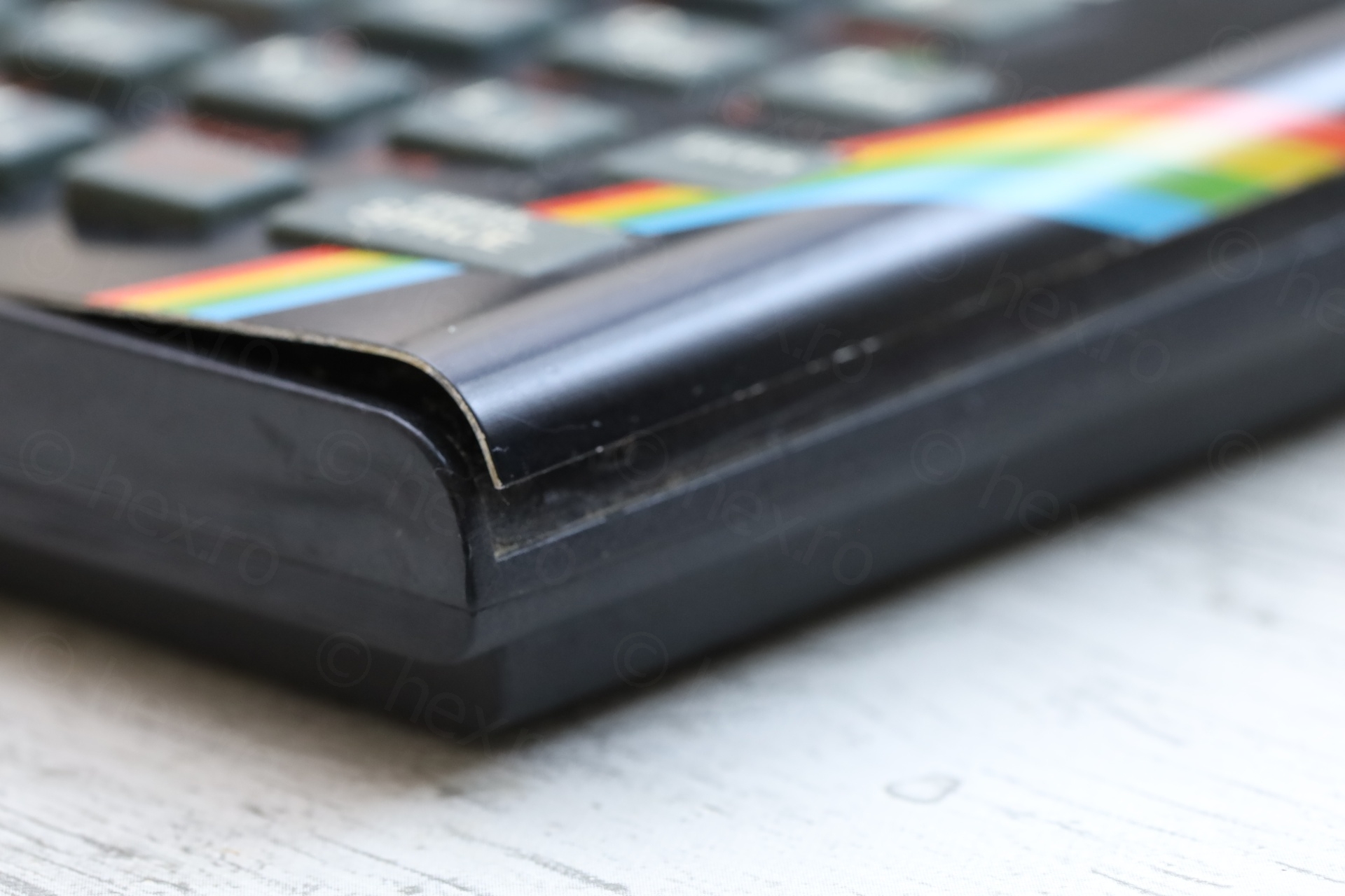
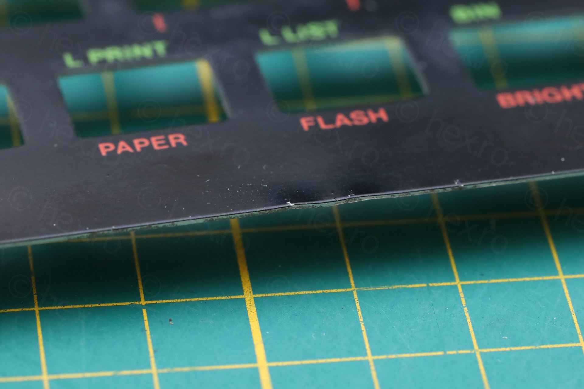
Visual checks
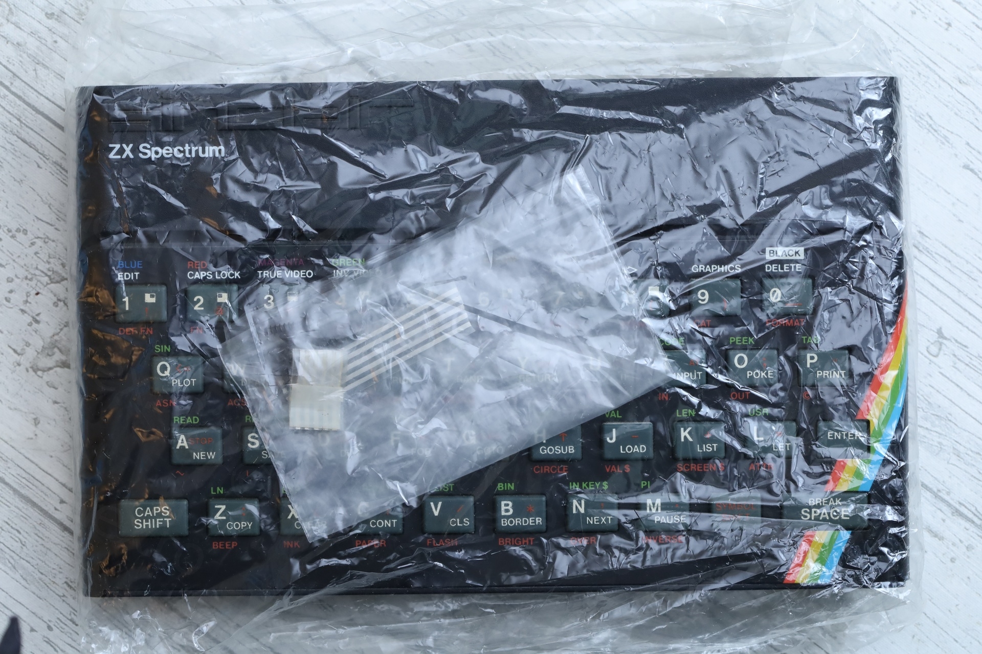
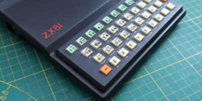
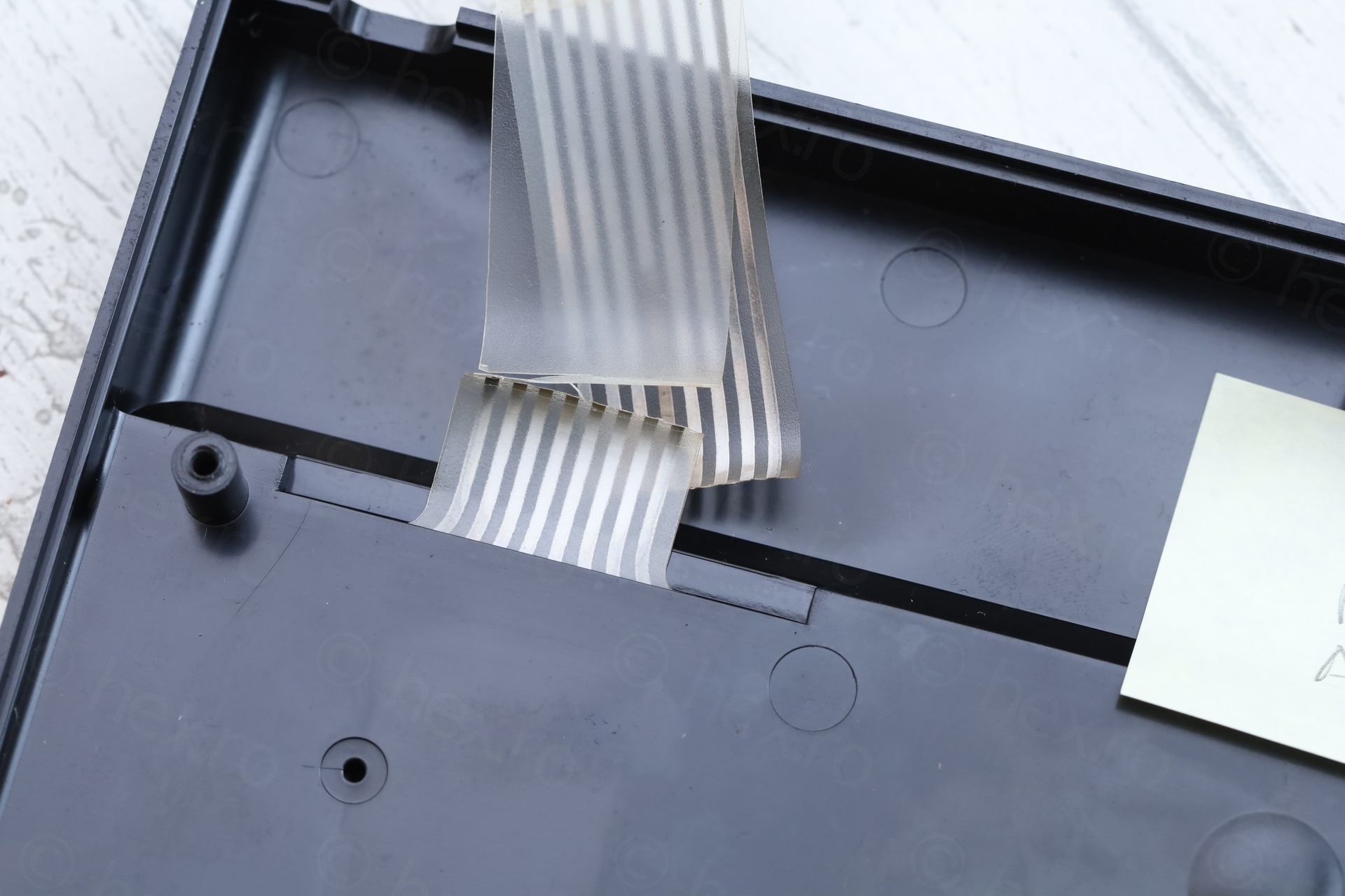
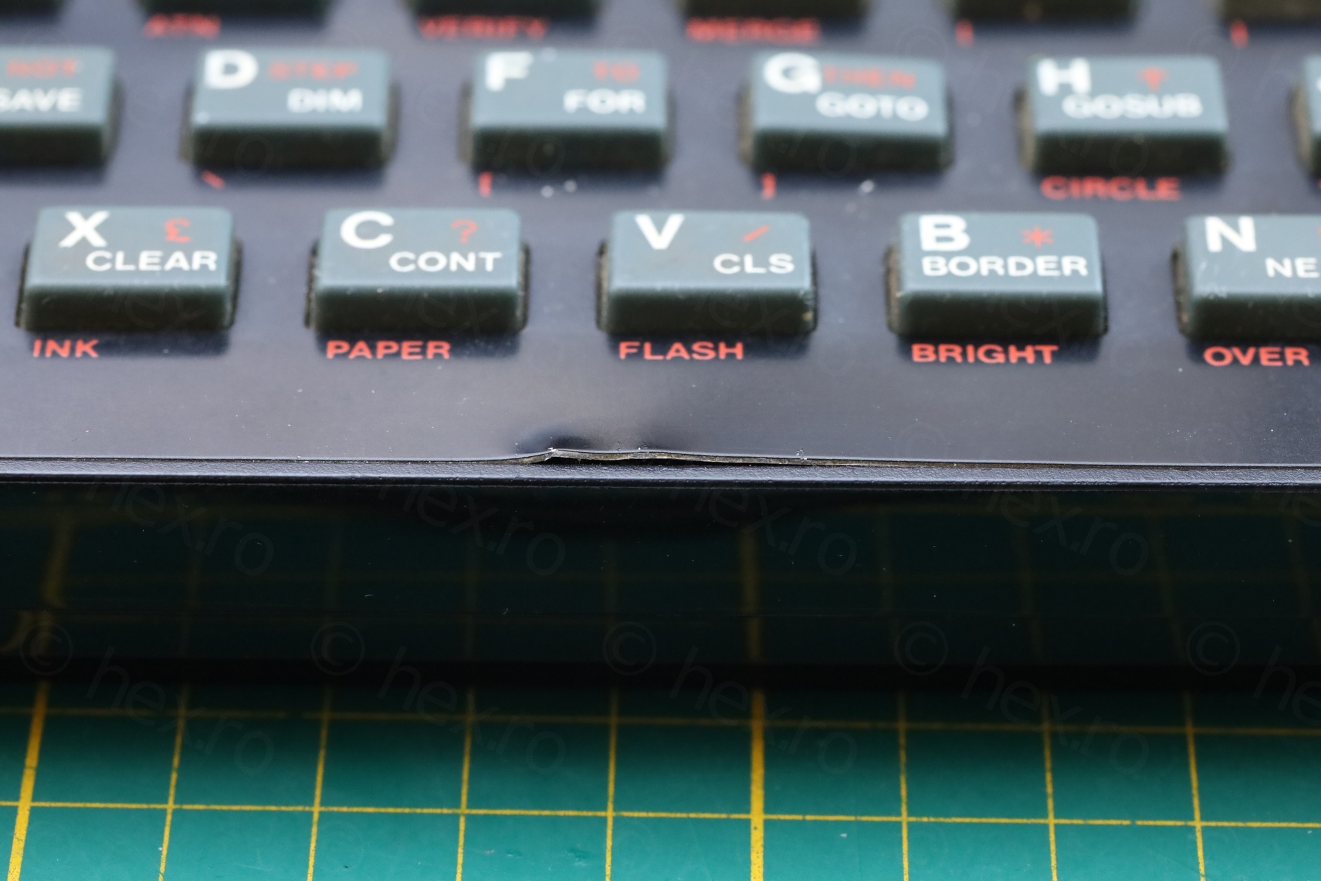
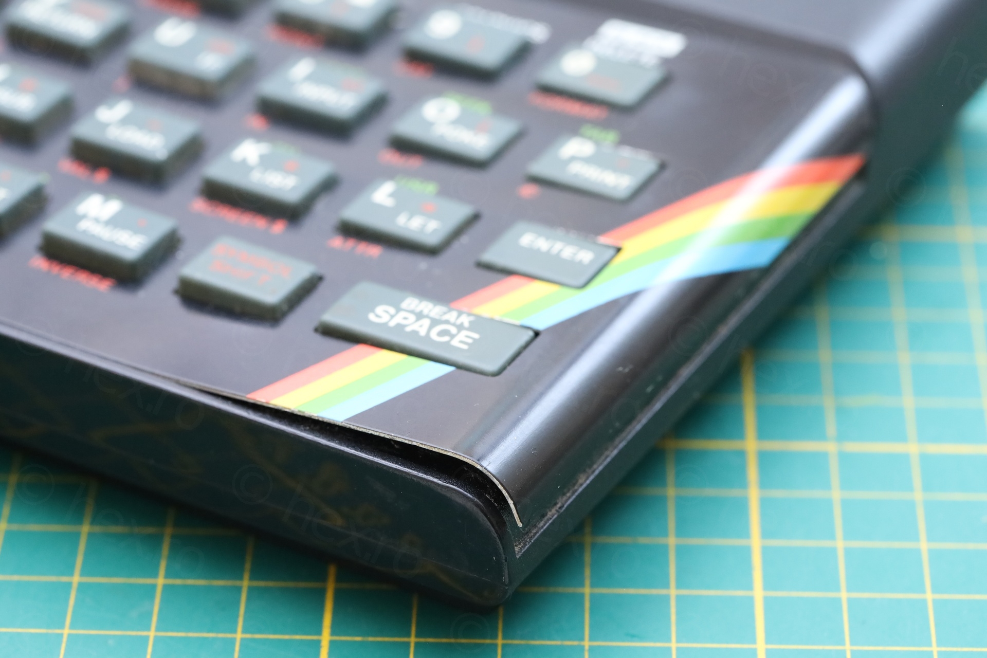
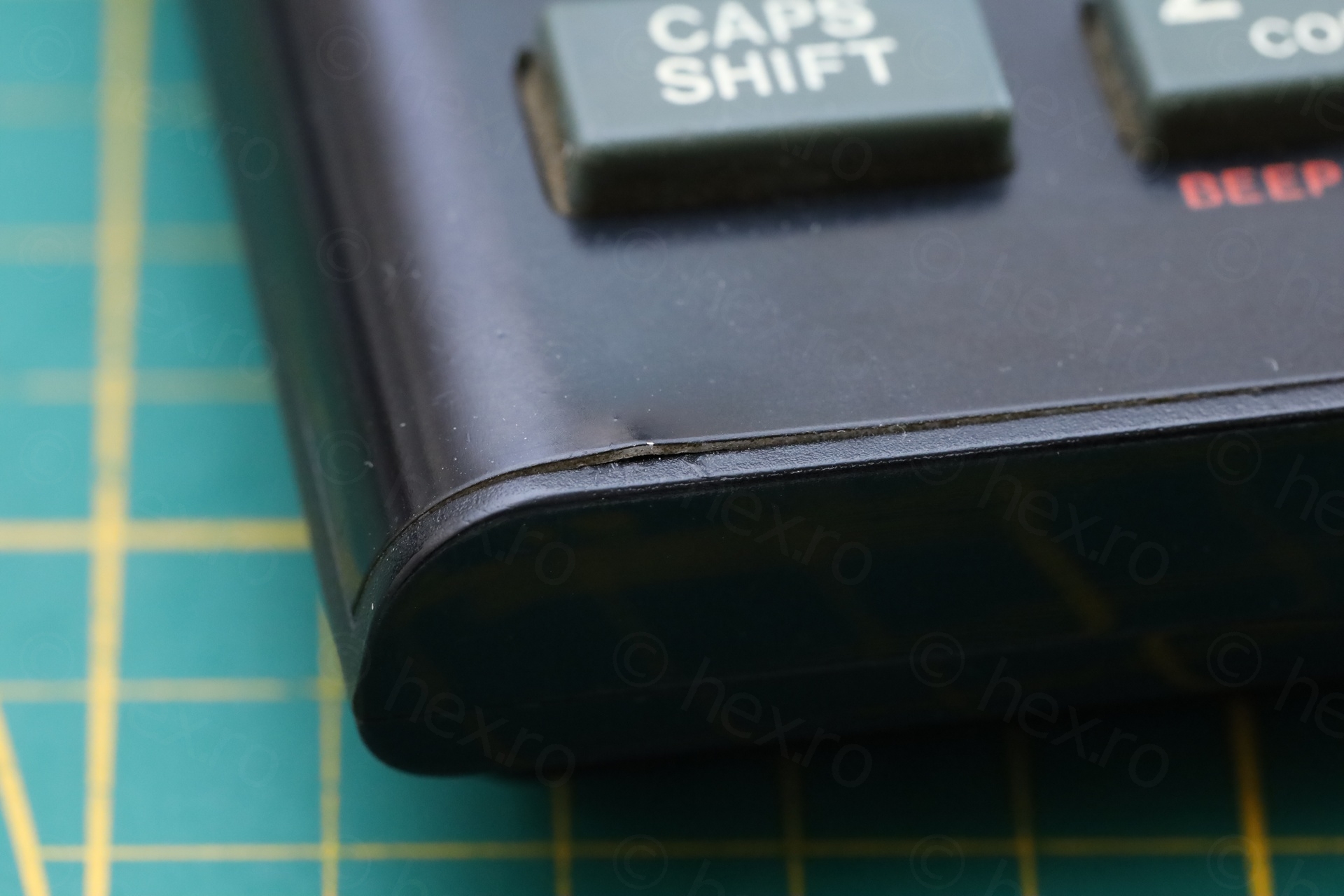
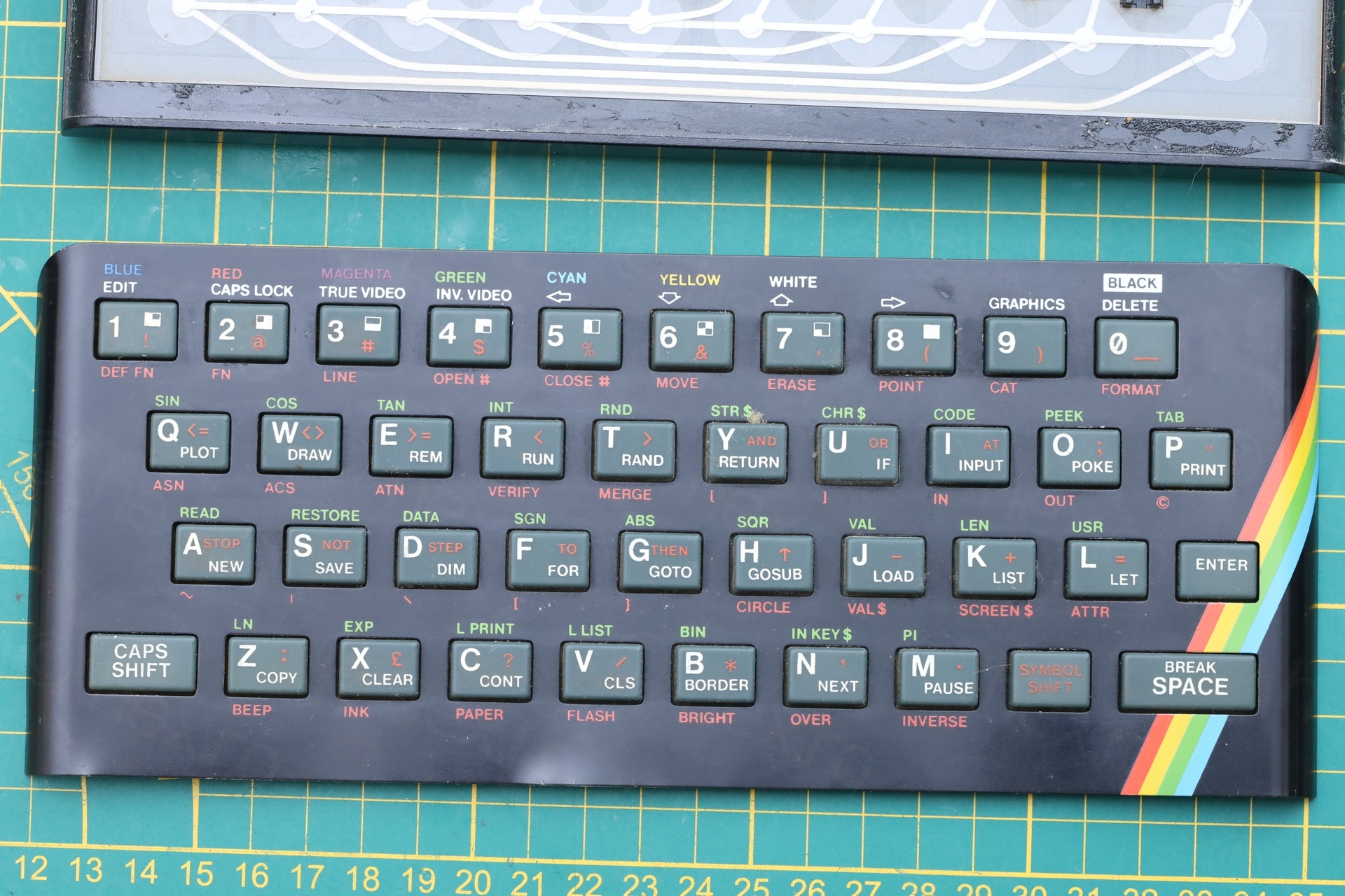
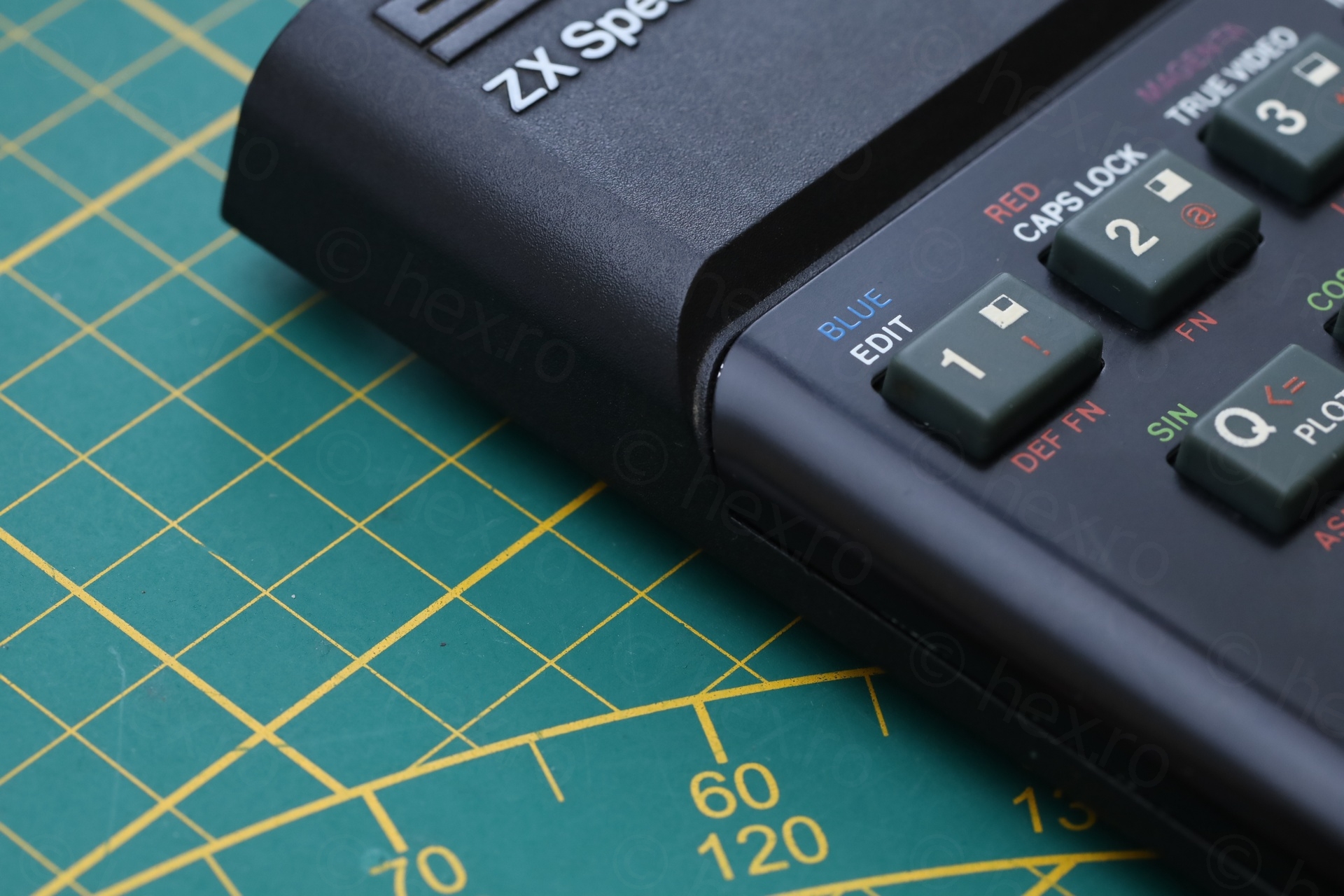
Having a closer look at the face plate, it seems the seller tried to peel the face place but gave up mid way:
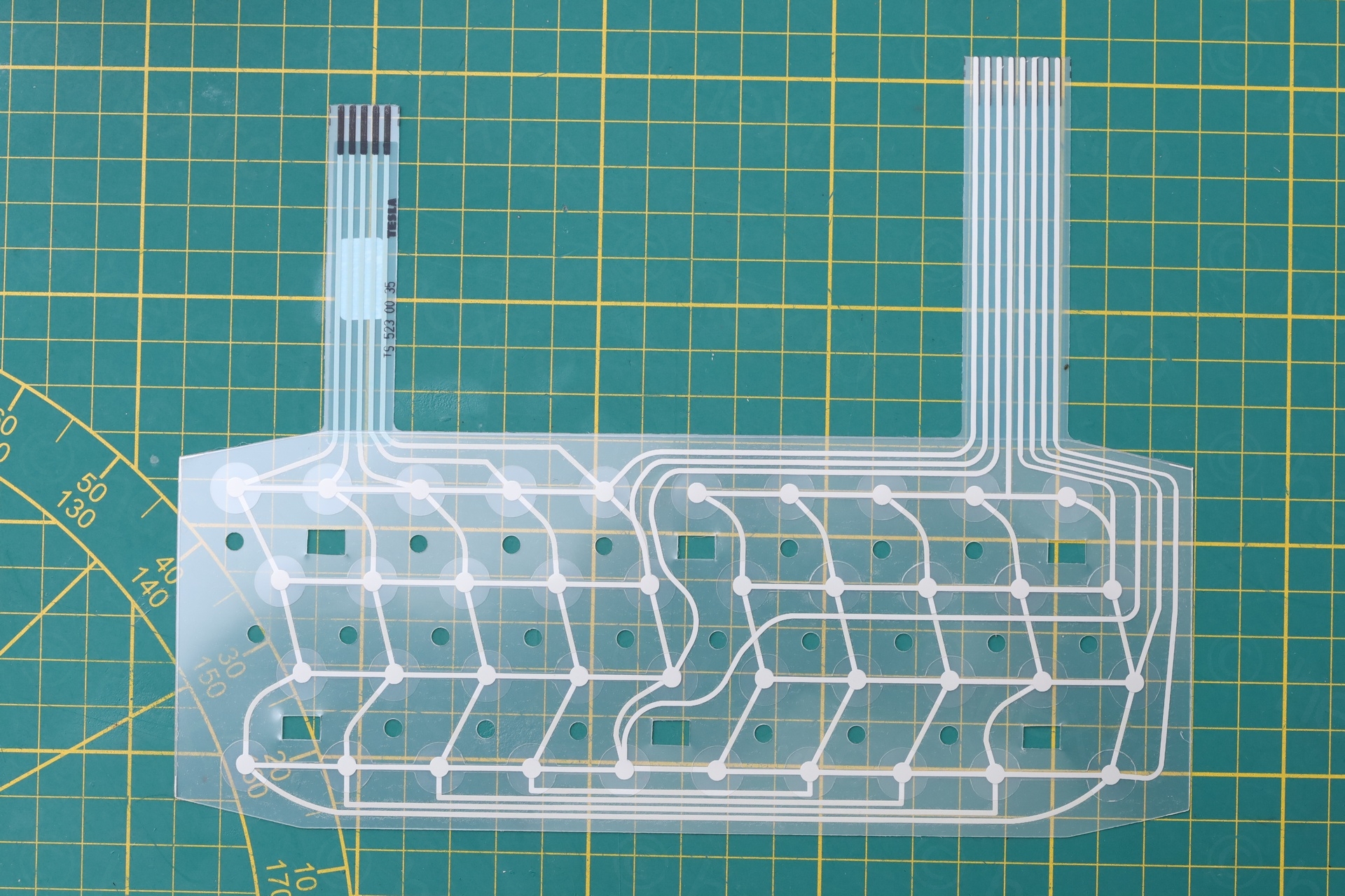
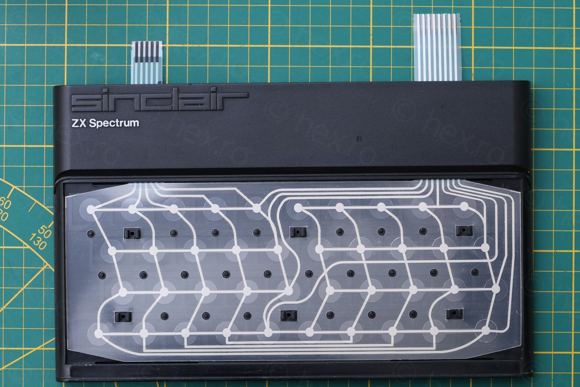
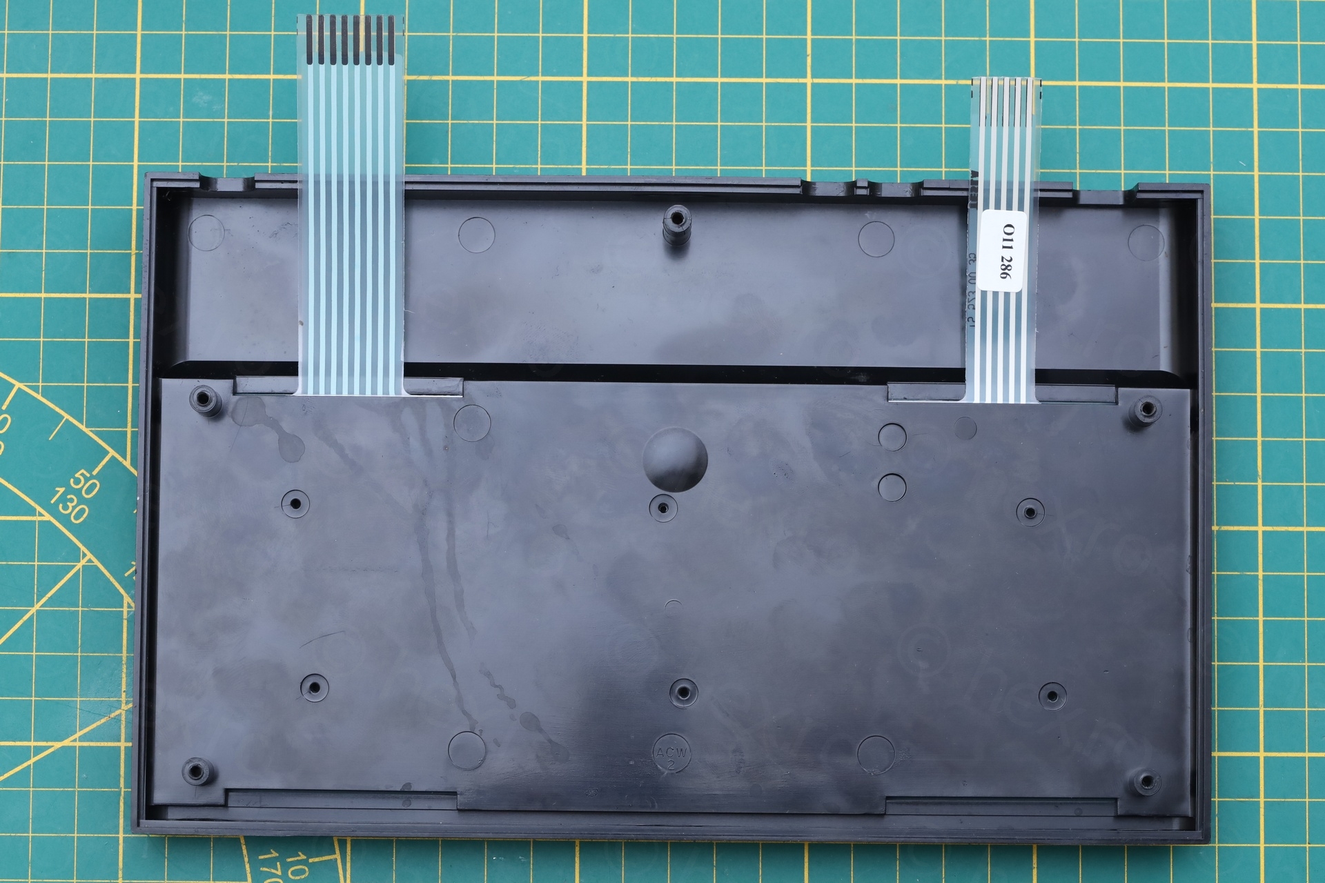
The keyboard membrane connectors were also torn:

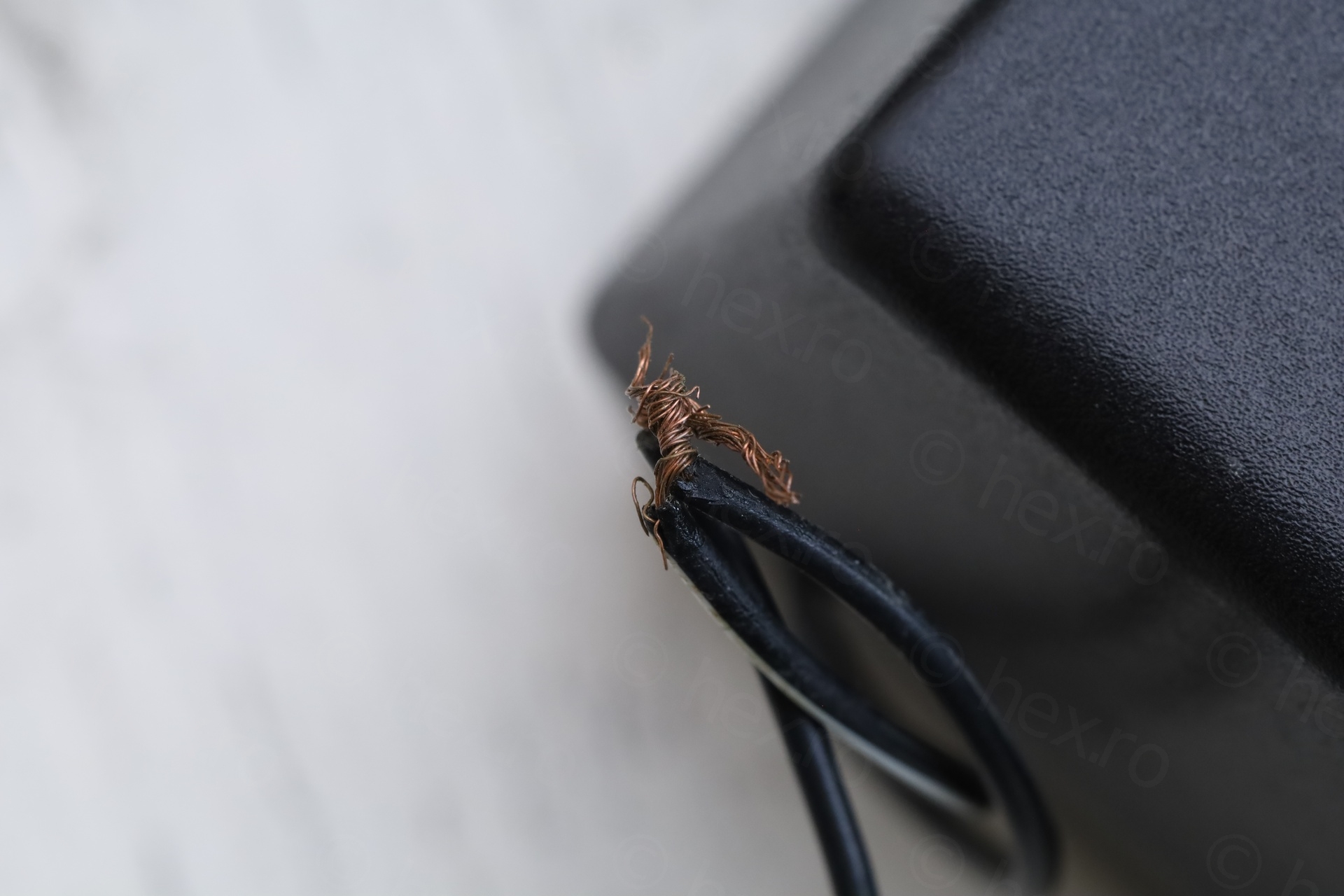
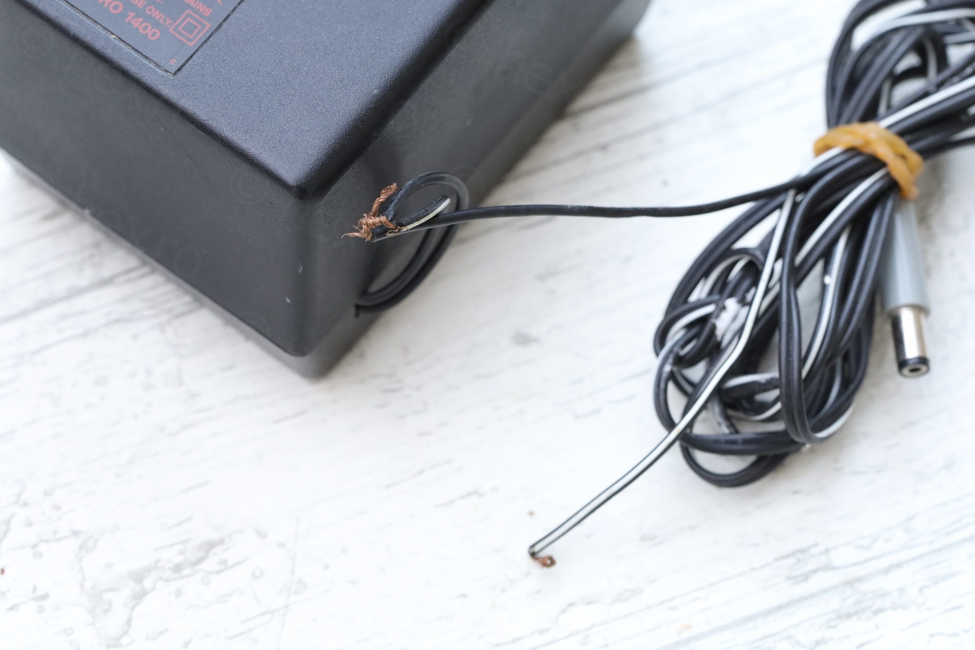
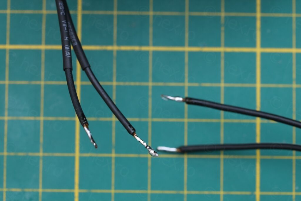
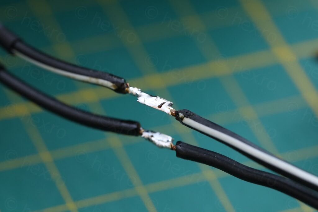
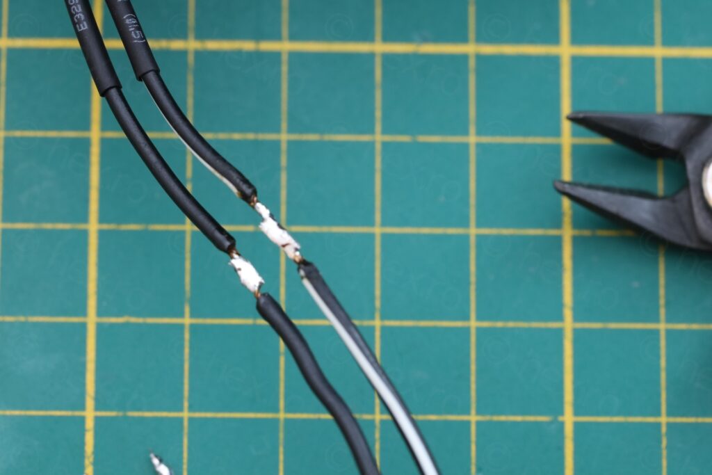
The power supply low voltage wire was split the ends tied into a short. I really nope nobody tried to plug it on like this 🙁
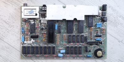
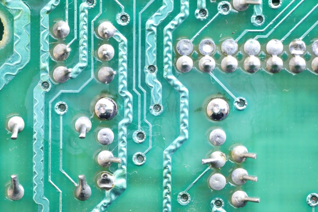
The motherboard had no traces of work being done to it. This is both good and bad. No hints where to look. Is it just the mechanical damage of the membrane ?
Electrical checks
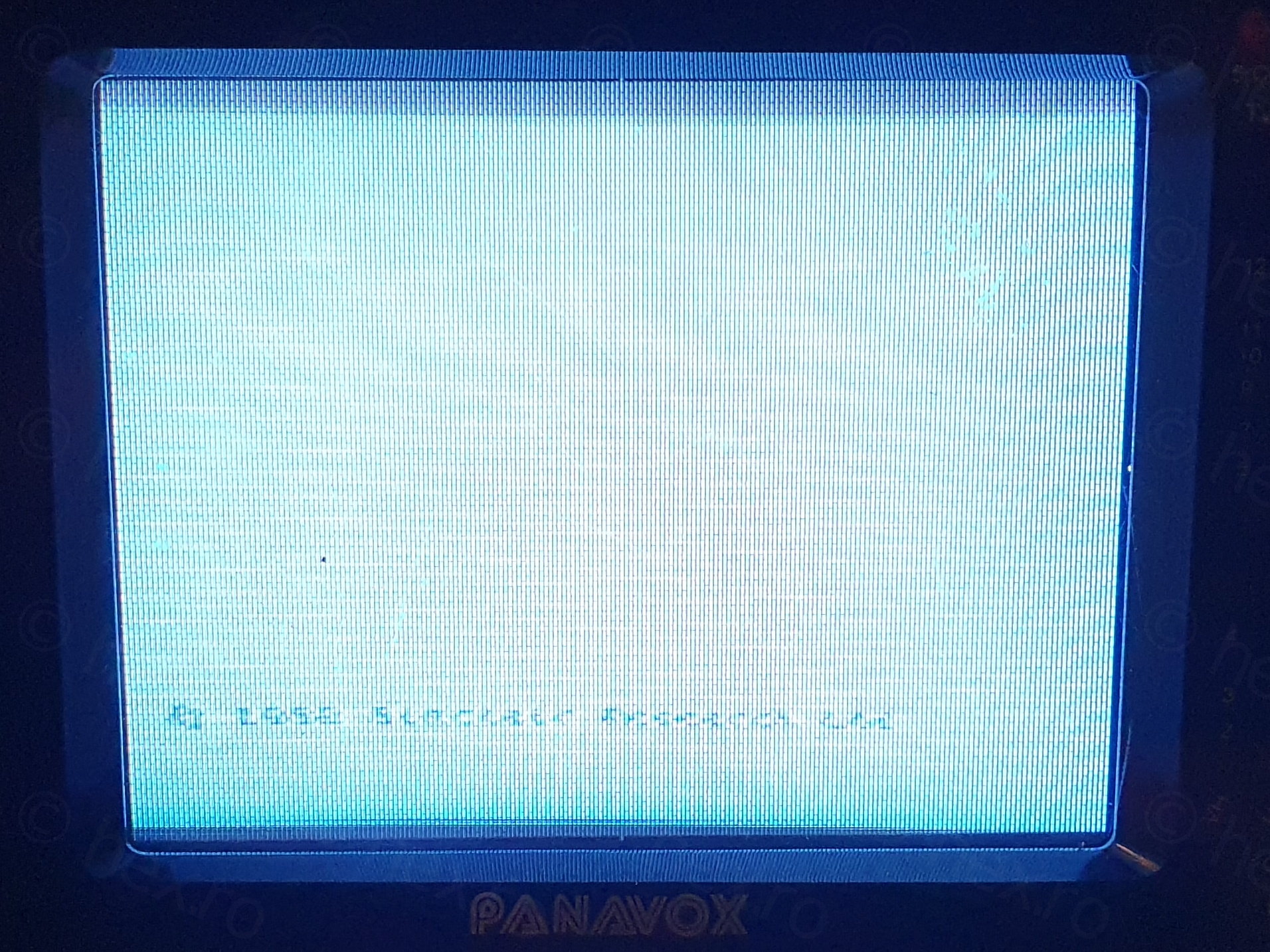
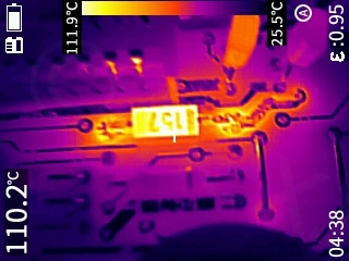
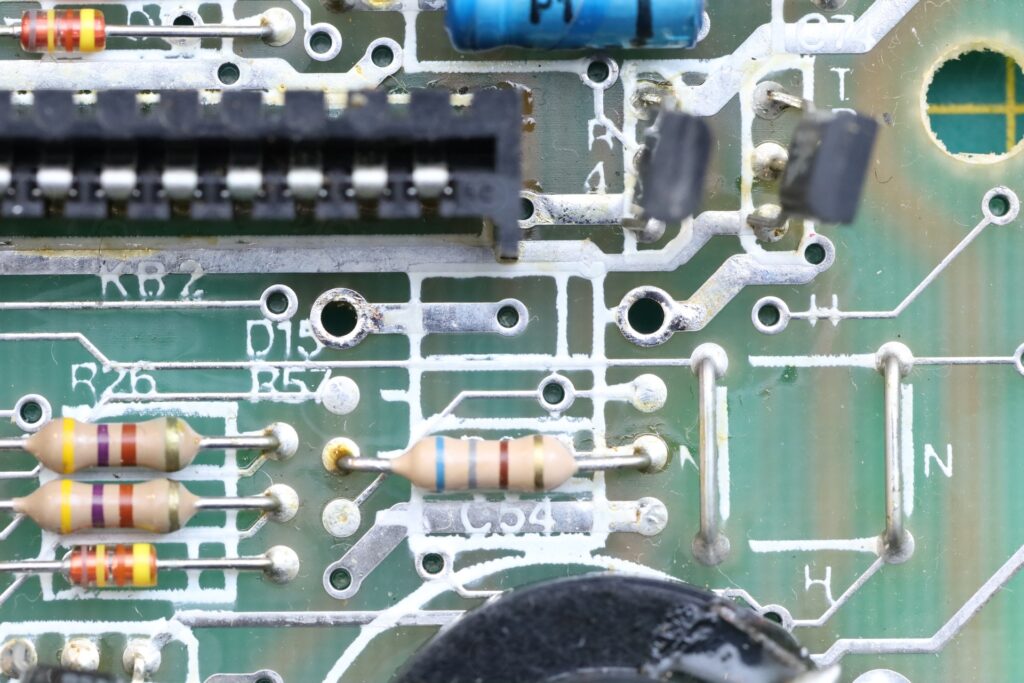
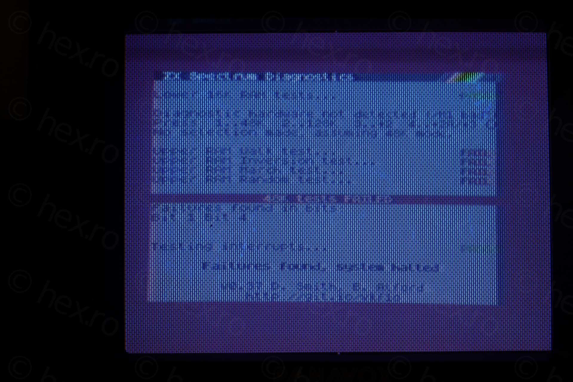
I powered on the computer. Power supply was limited to 1A. Spectrum booted, but not all was good. The -5V line was around -2V, image was tearing sideways (lines were jiggling, some lines were going left, some right). The D15 diode (BA157) in the DC-DC is was getting very hot at 110C and that’s when I pulled the power. Consumption was around 800mA.
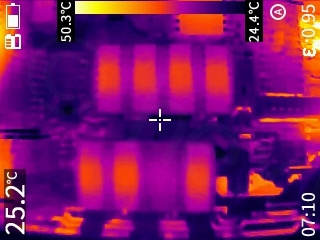
One last thing I managed to spot was that one higher RAM IC was not getting hot.
Diagnosis
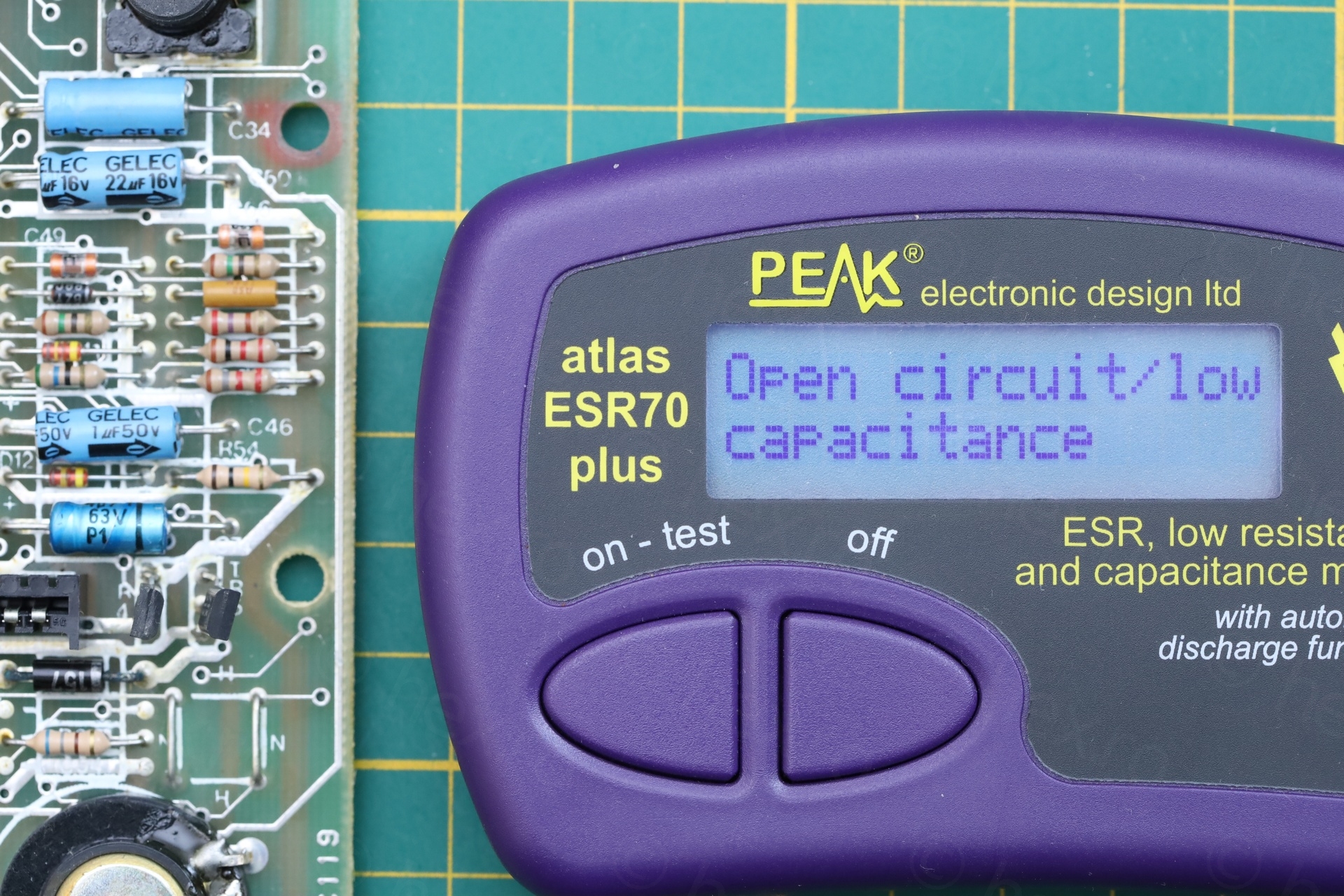
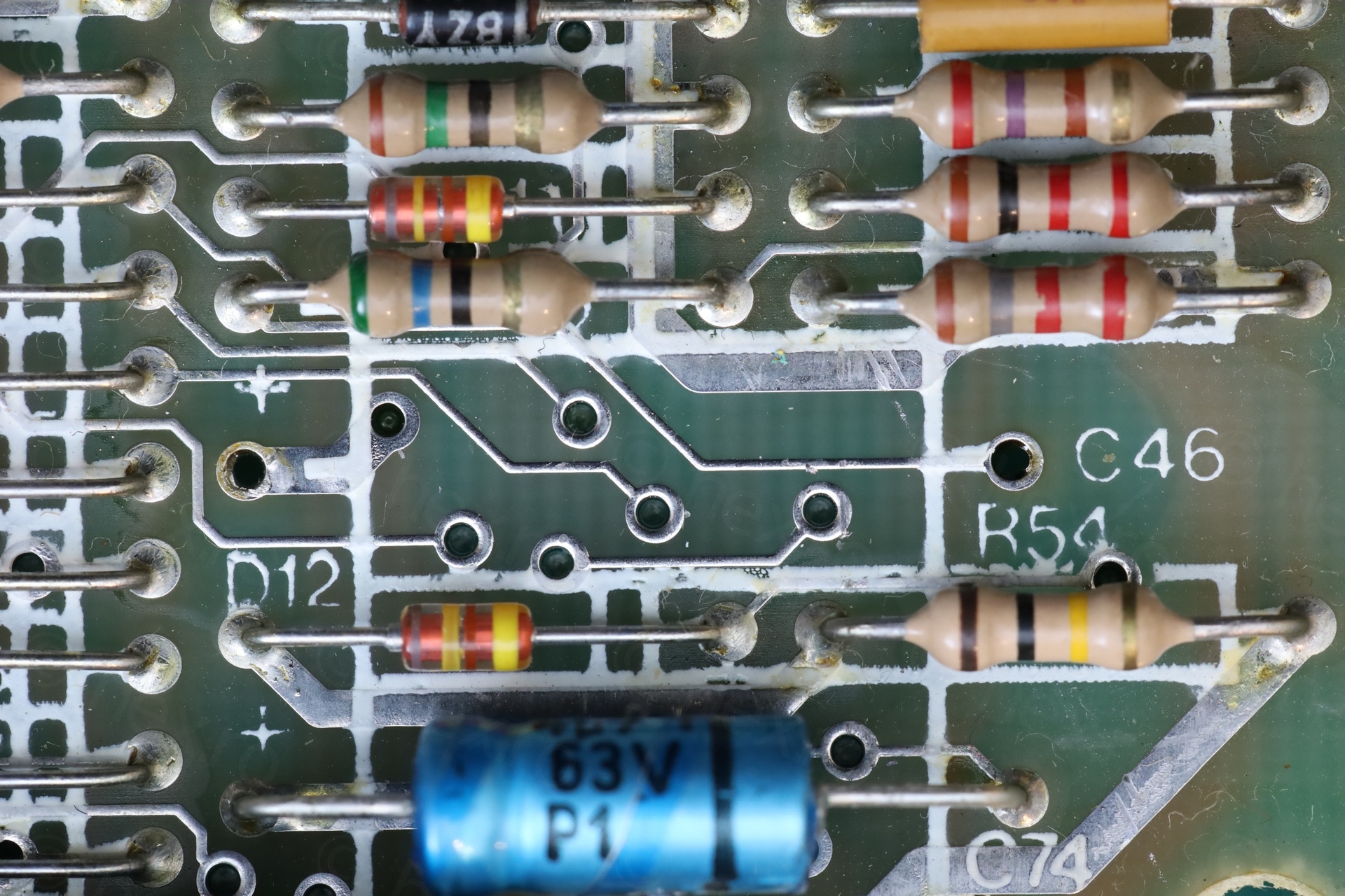
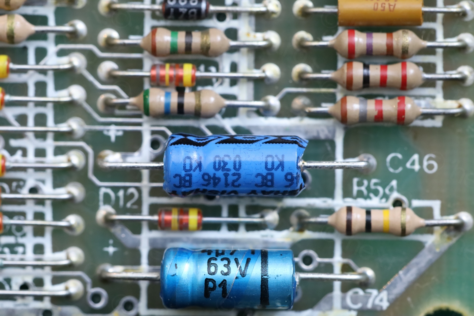
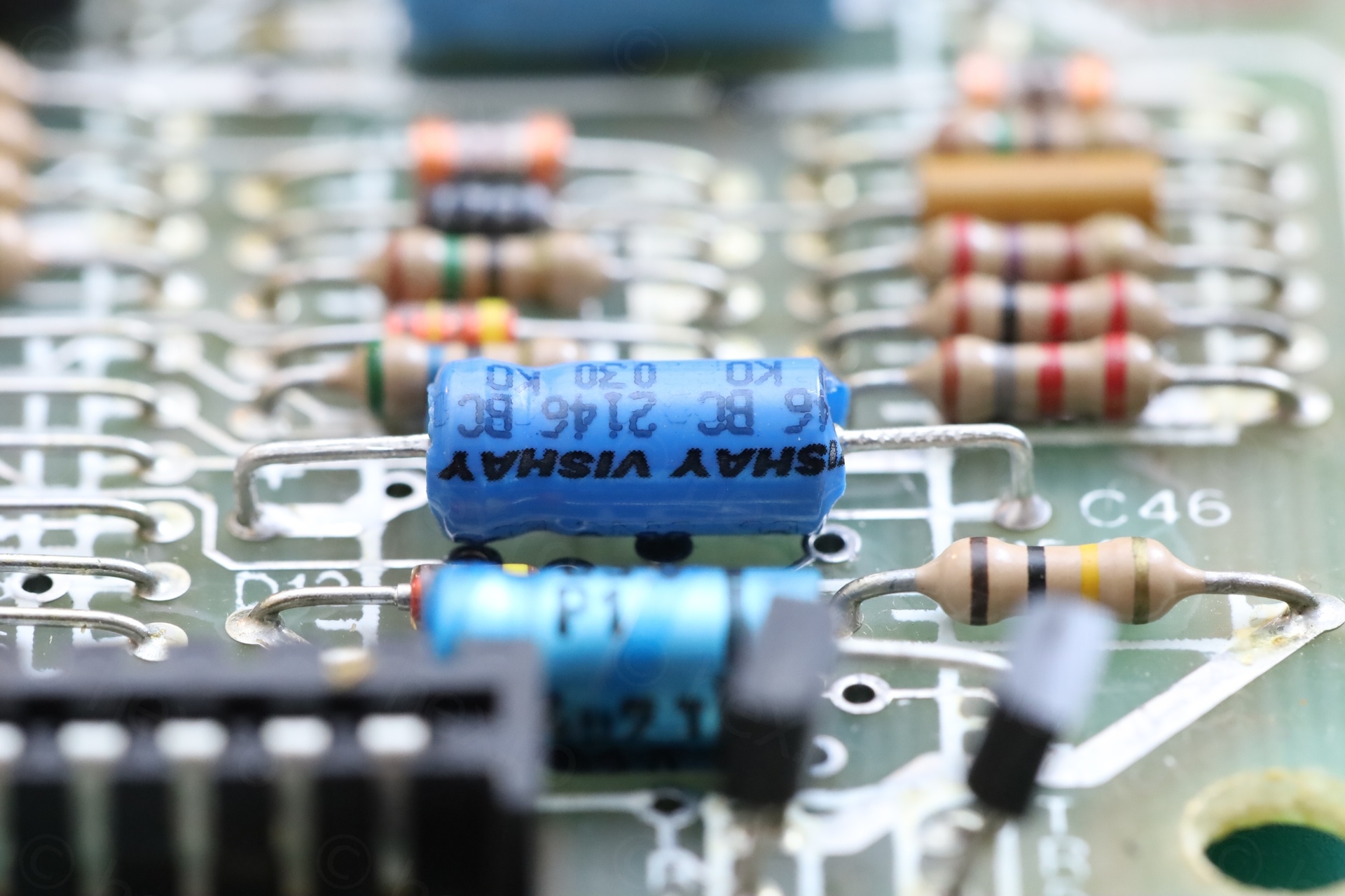
C46
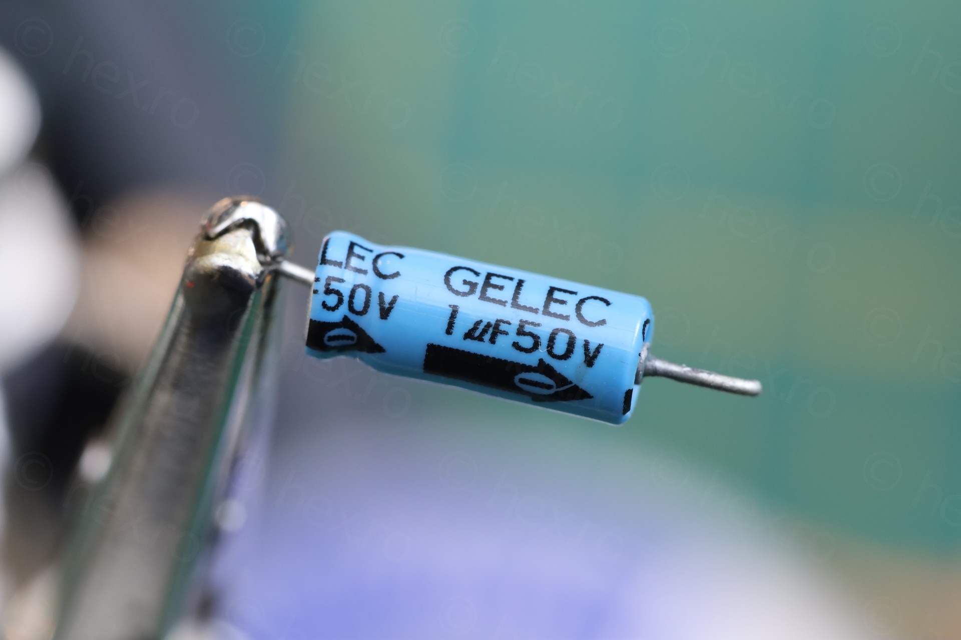
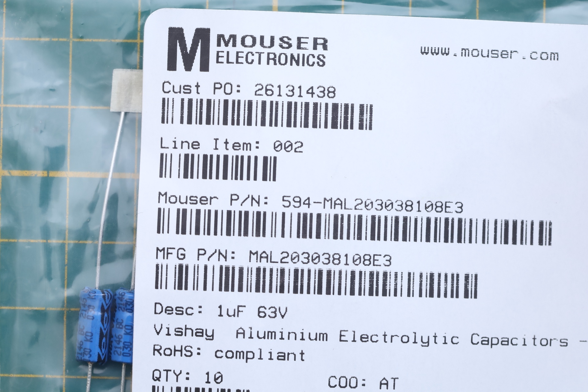
The easiest things to check are the capacitors. I found C46 open. Since this is on the -5V line, I swapped it with the closest Vishay replacement (1µF @ 63V, instead if 1µF @ 50V).
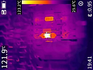
After swapping it, I was ready with the infrared camera, not even thinking of the voltmeter. Now, the diode isn’t getting hot at all. BUT R55 resistor reaches >100C in 2-3 seconds. And the -5V is back, but the 12V line dropped towards 10V. Consequently the image is even more distorted now. I managed to see with the corner of my eye: consumption > 900mA! Uff.
D15
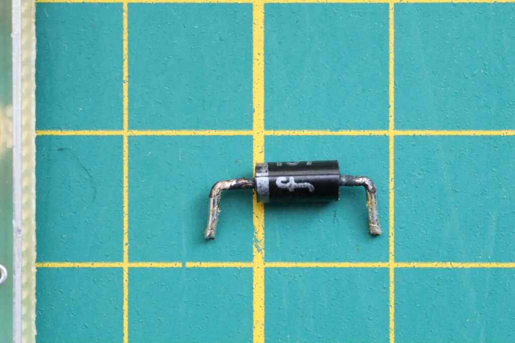
R55 getting very hot did not discourage me this time, is known territory, I had the same issue with a previous issue 4b board. The Repair manual here https://k1.spdns.de/Vintage/Sinclair/82/Sinclair%20ZX%20Spectrum/Repair/ZX%2048k%20repair%20guide%20(ian%20worsley)/rep_spec.html says that: “You may also visually check , to see that R79 2k2 (Issue 6) or R62 15R (Issue 6) or R55 56R (Issue 4 and less) are not discoloured. If any of the 55R resistors are badly discoloured, change D15 BA137 on all models.“
D15 was the one getting hot before the capacitor change. Very likely it is damaged. I had the replacement in stock already, BA157-E3/54 from Vishay:
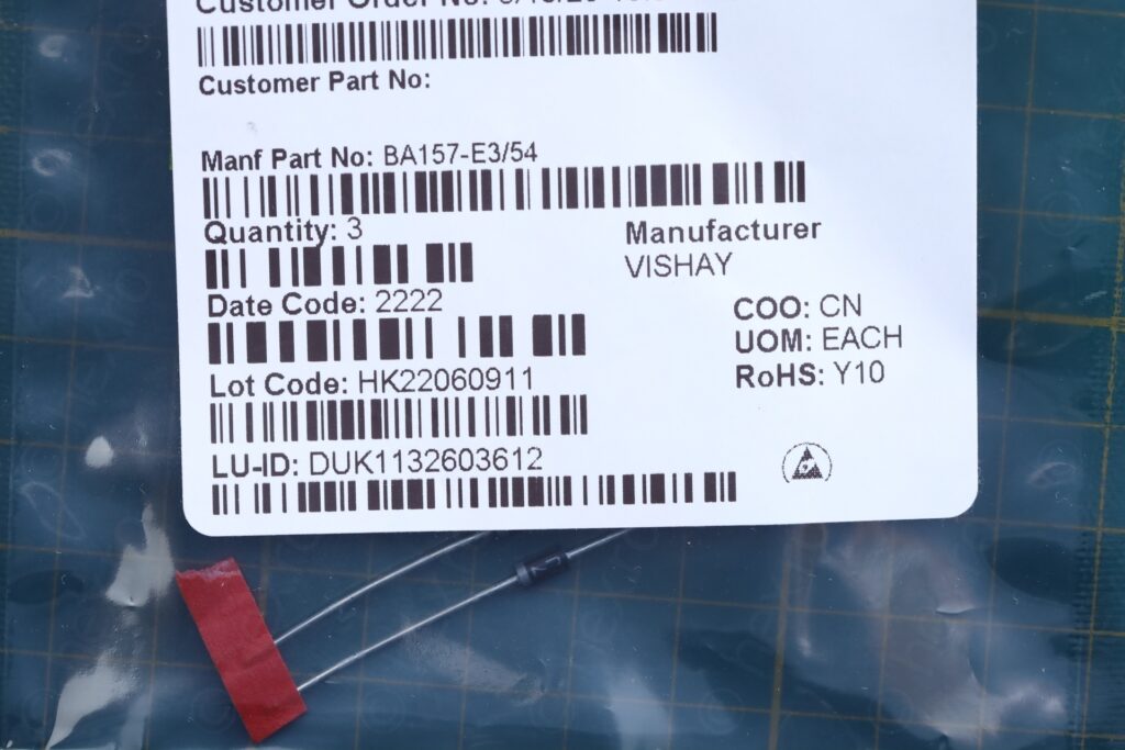
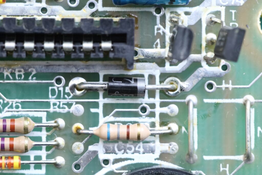
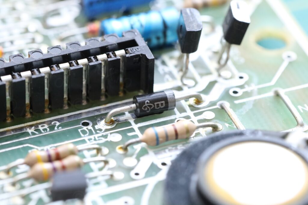
After changing the D15, things are finally working properly. Image is stable on the screen, the 12V line is 12.2V, the -5V is -4.9V and +5 is 4.98V. The R55 is still hot, at around 65C. Consumption of the board is down to 650mA.
Bit 1 and 4 – Upper RAM ICs
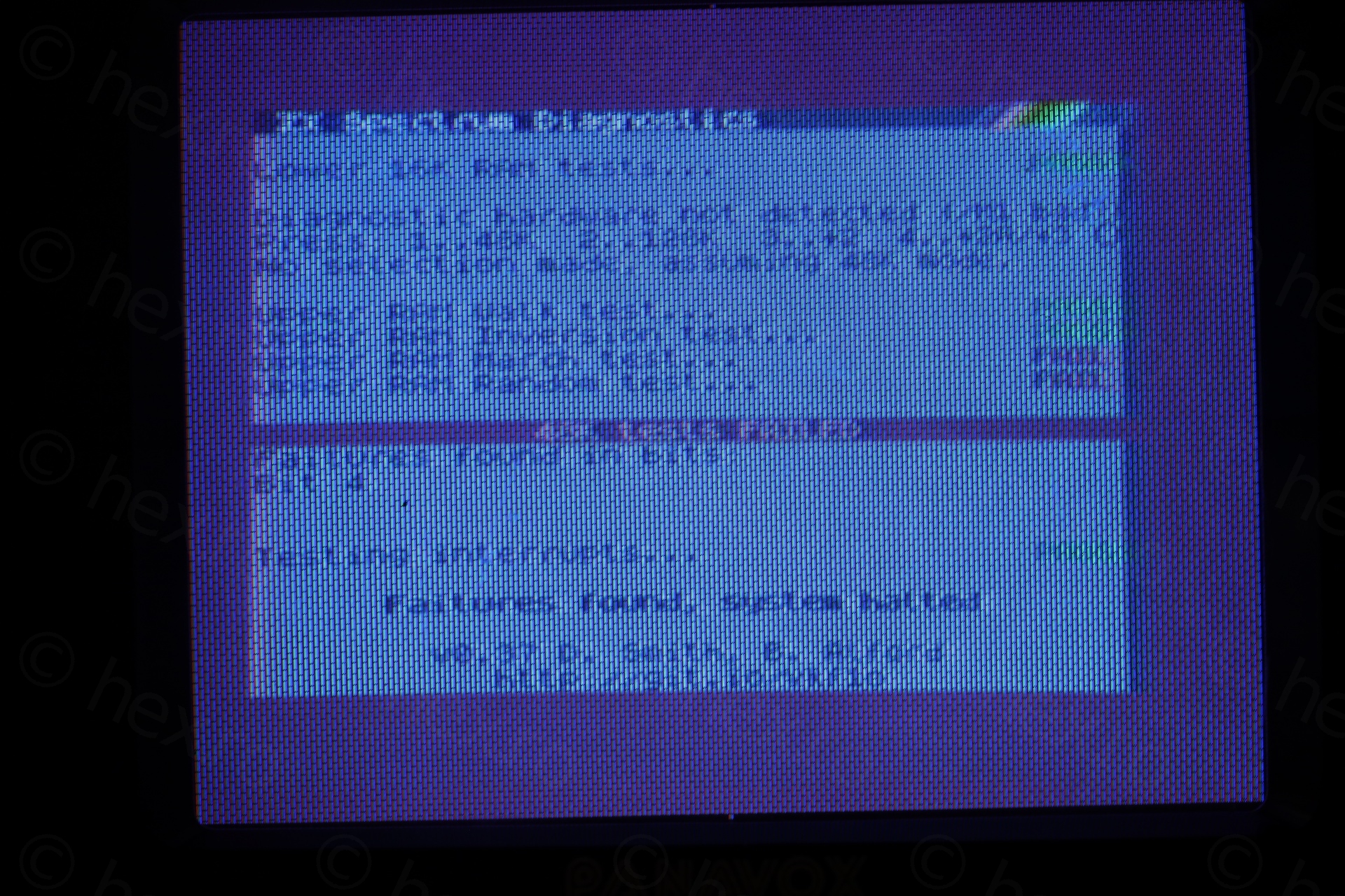
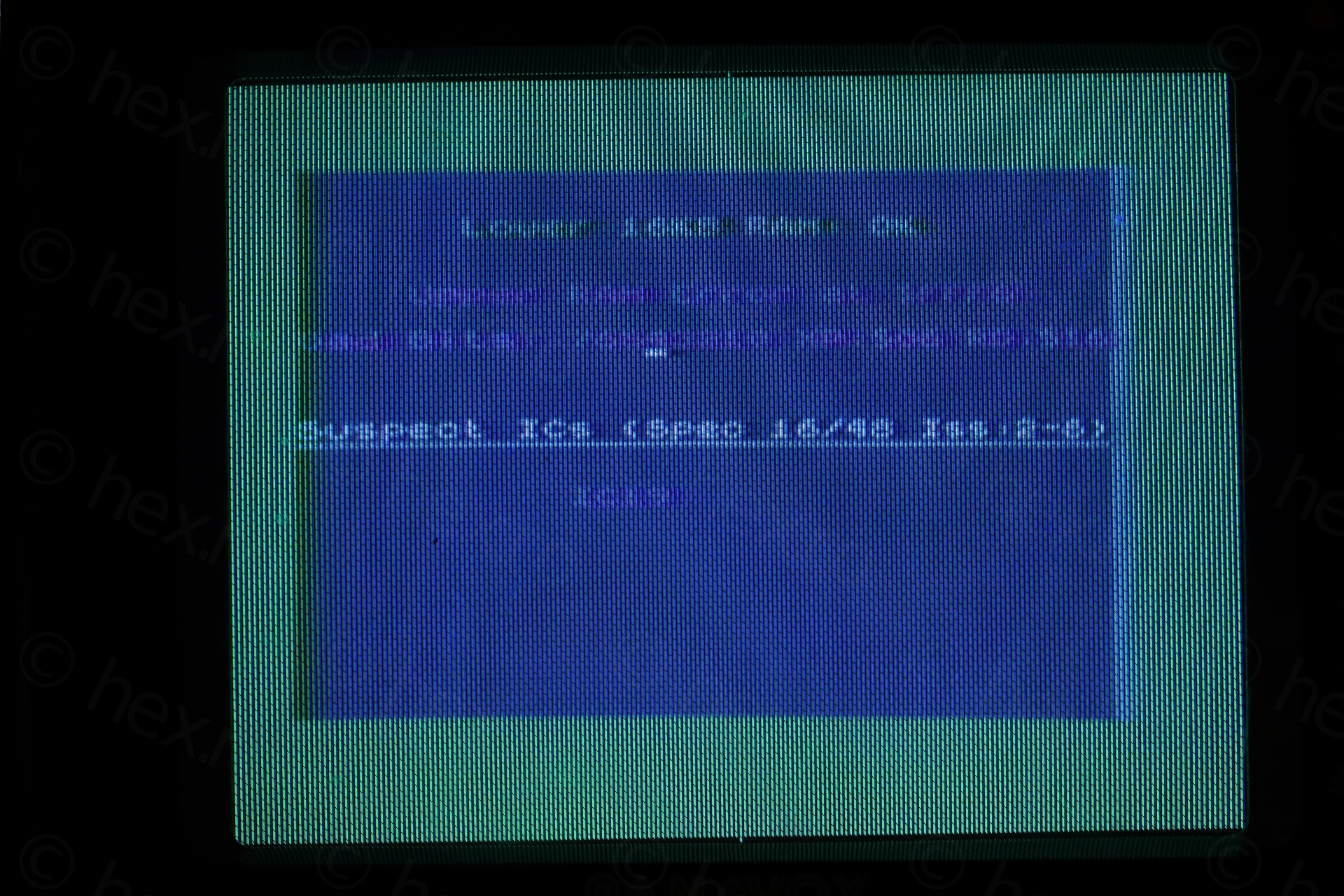
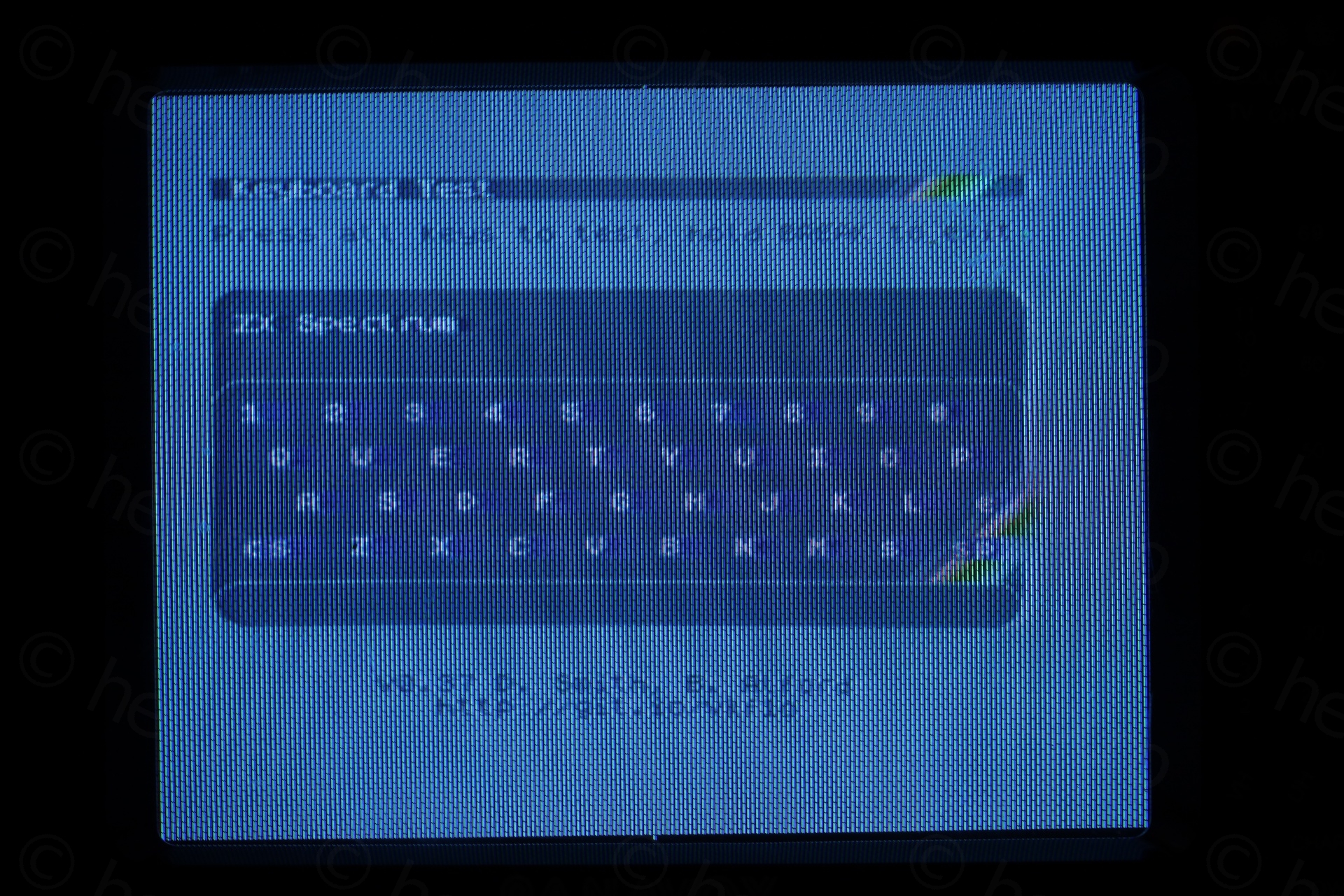
It was time for the first diagnostic ROMs.
Thankfully, lower RAM test passed. But, ZX Diag was telling me bit 1 and 4 are damaged, in the high DRAM.
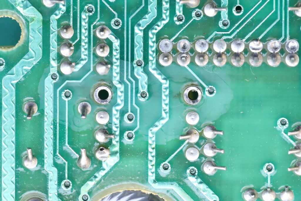
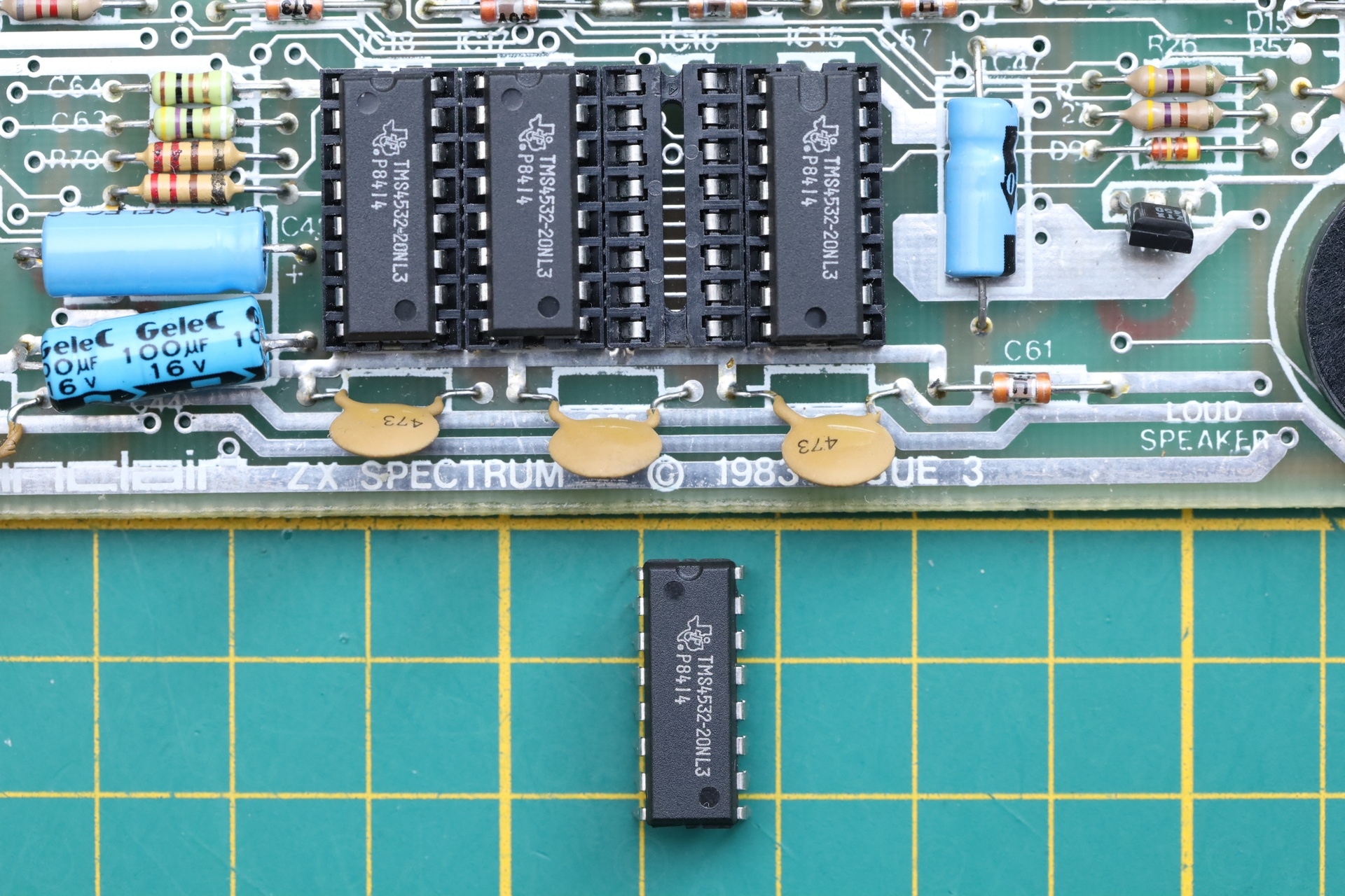
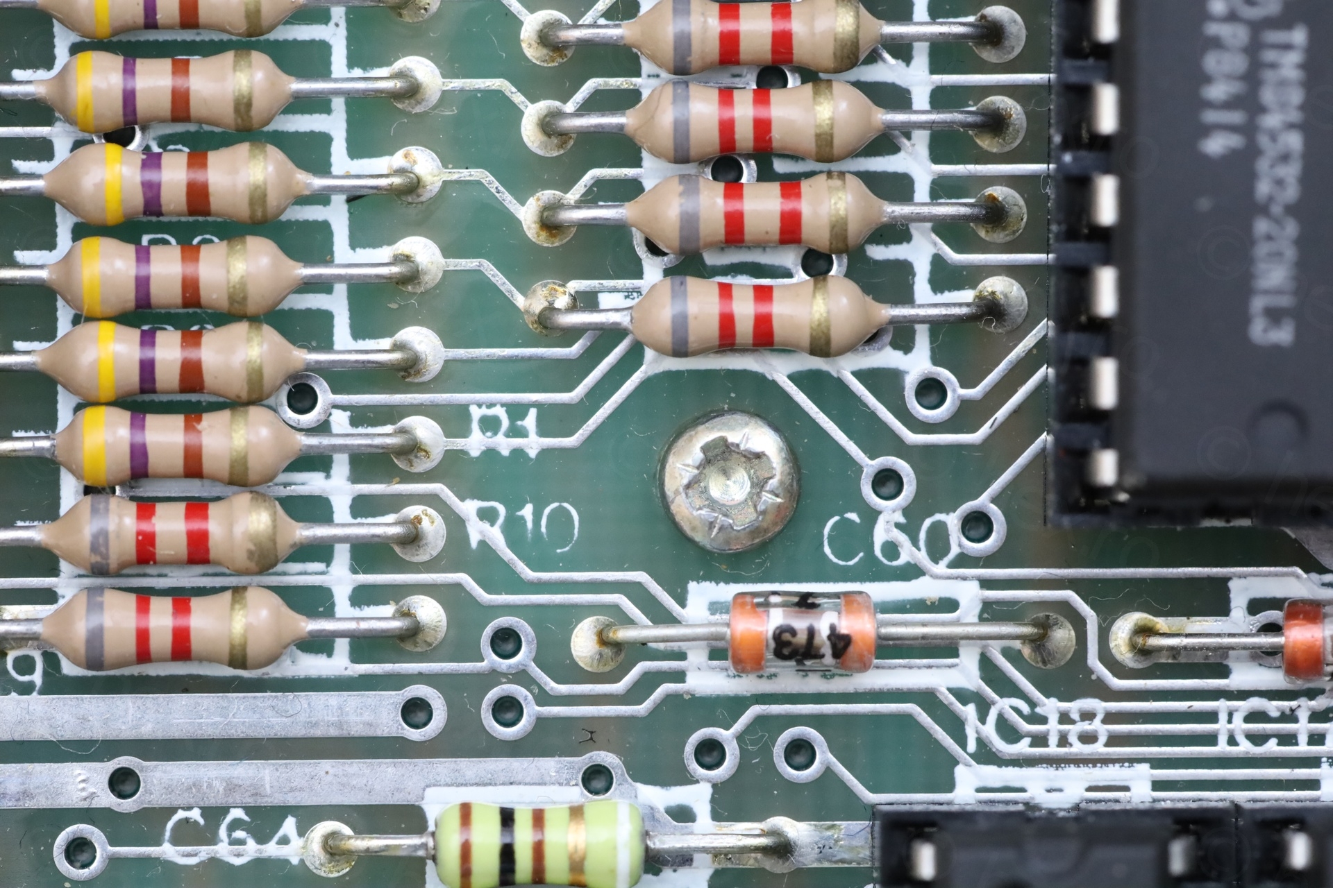
Looking at the board with the IR camera, it was obvious one memory chip was not warming up, that will be the first suspect and it matches the error reports.
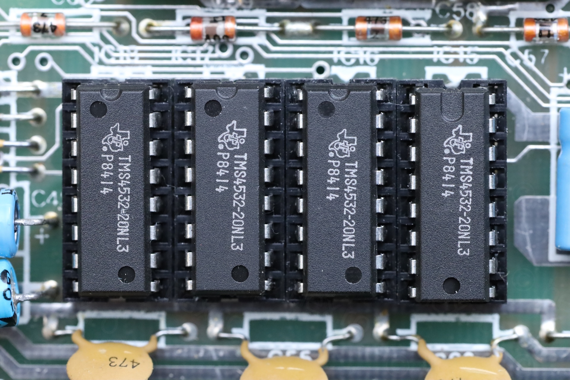
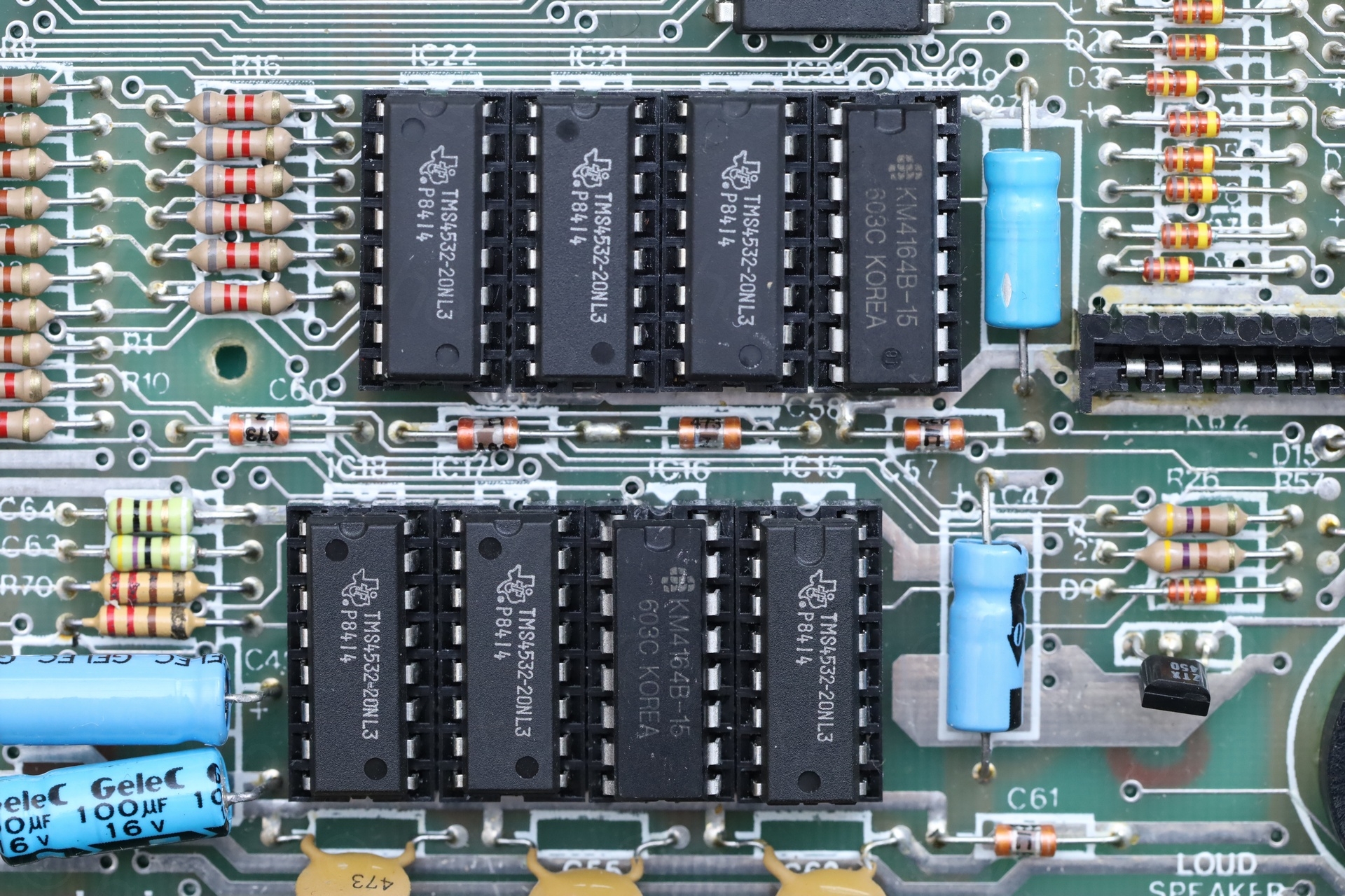
Board has TMS4532-20NL3 memory, and thankfully I didn’t rush to buy the TMS4532-20NL4 replacements. The CAS signal doesn’t match (found the information here: https://sinclair.wiki.zxnet.co.uk/wiki/DRAMS )
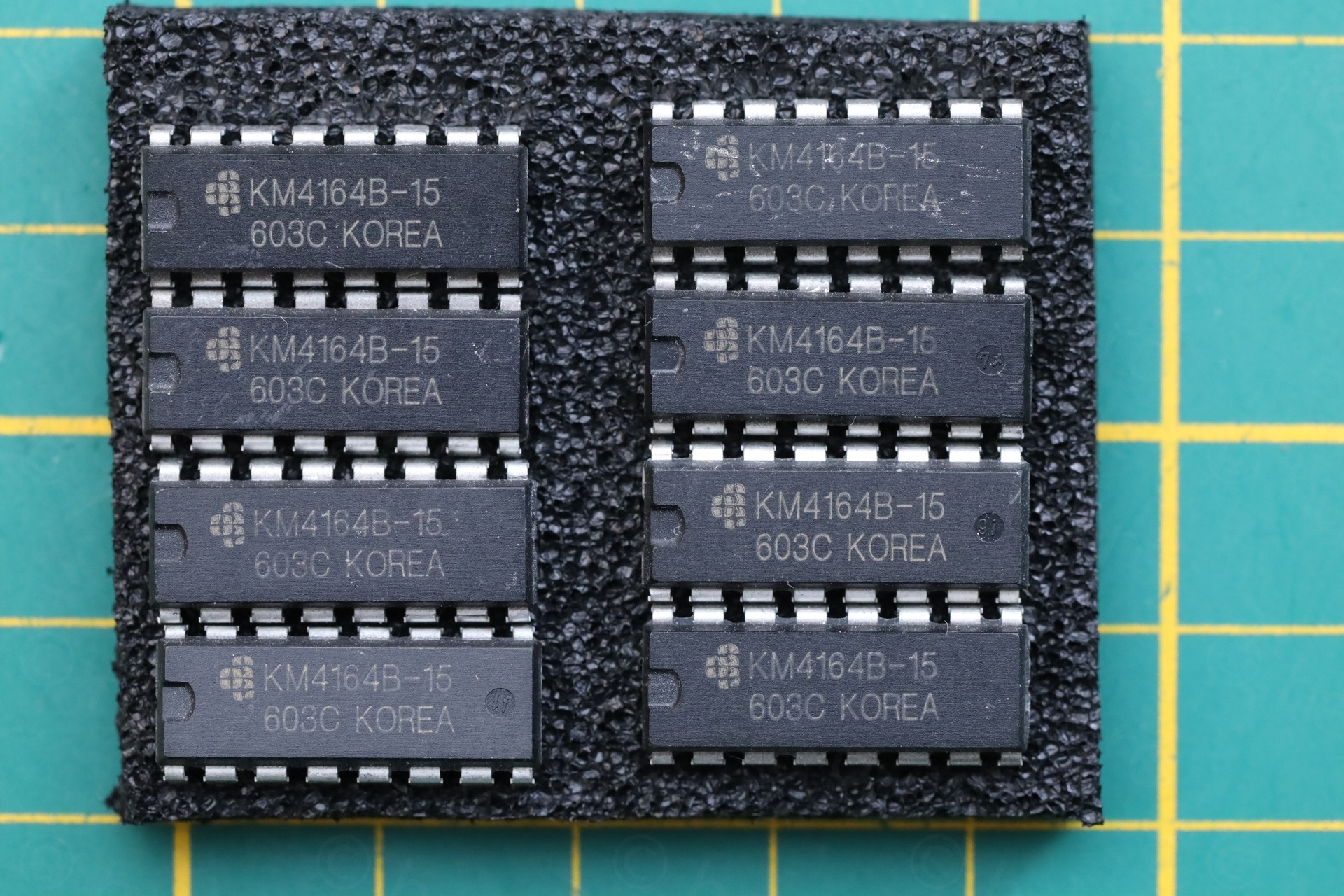
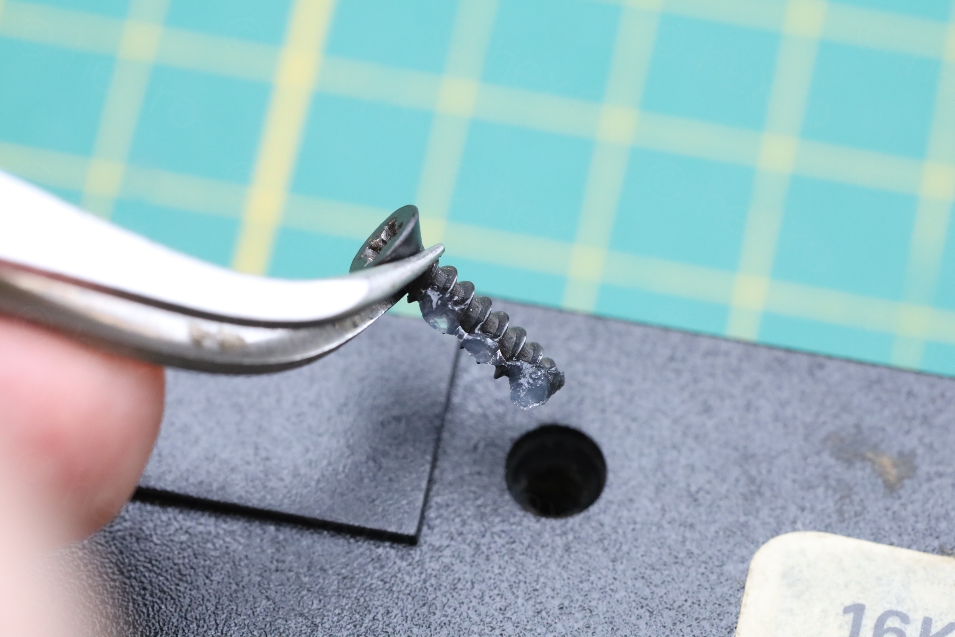
I replaced the cold IC16 with KM4146B-15 after carefully removing it:
Memory checks were still not fine, IC19 needs to be reviewed:
Two ICs had to be changed – IC16 and IC19. KM4146B-15 were used as replacements:
Euro 1400 Power Supply
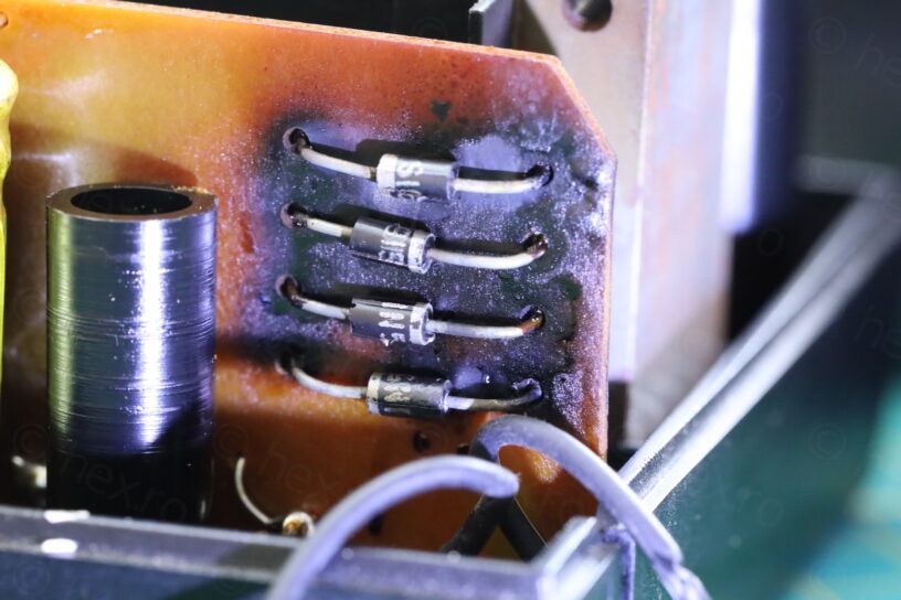
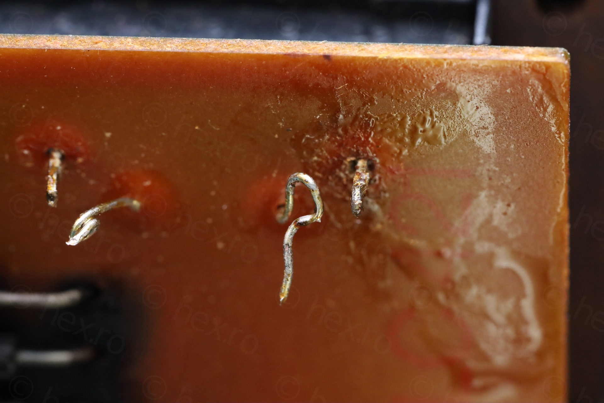
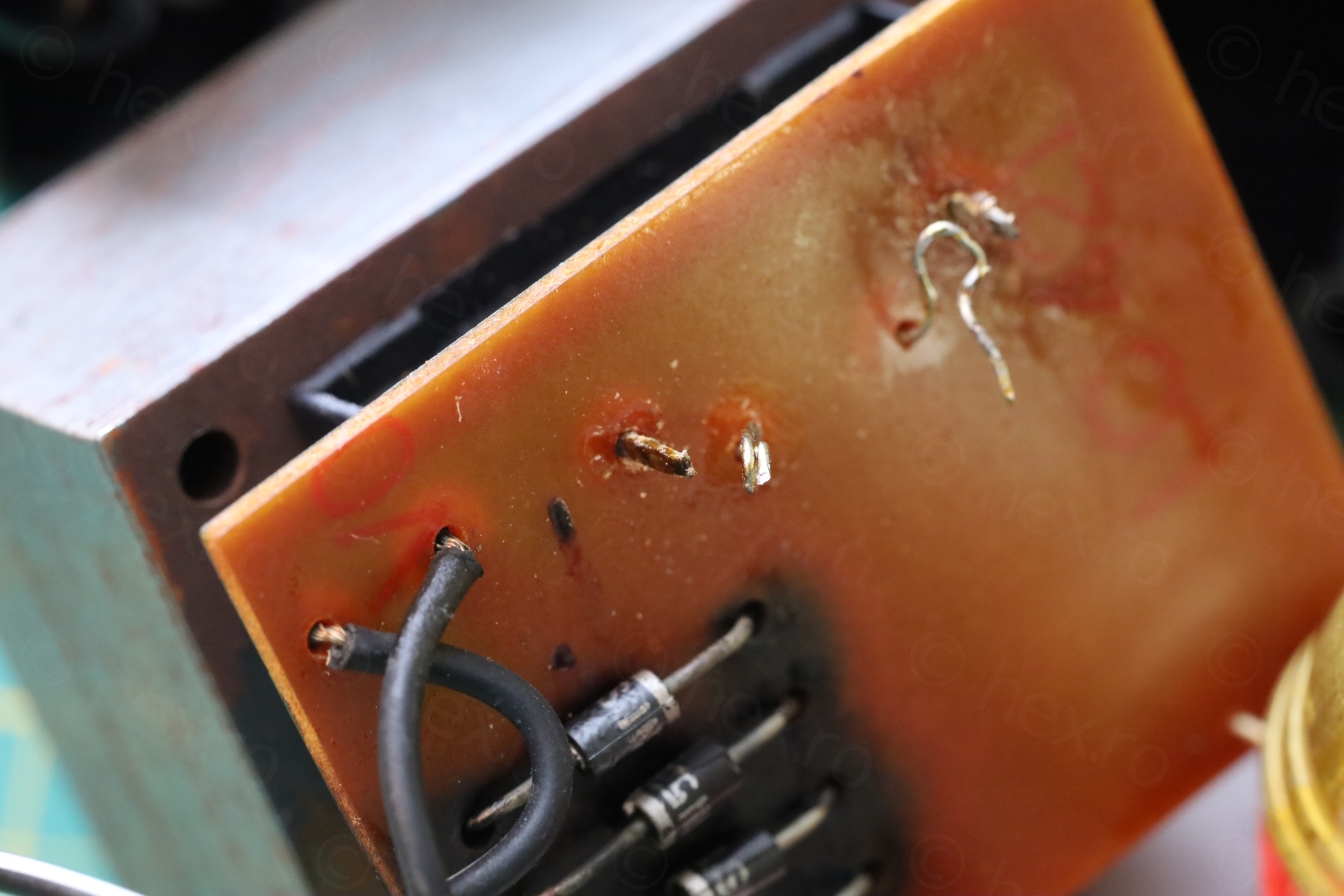
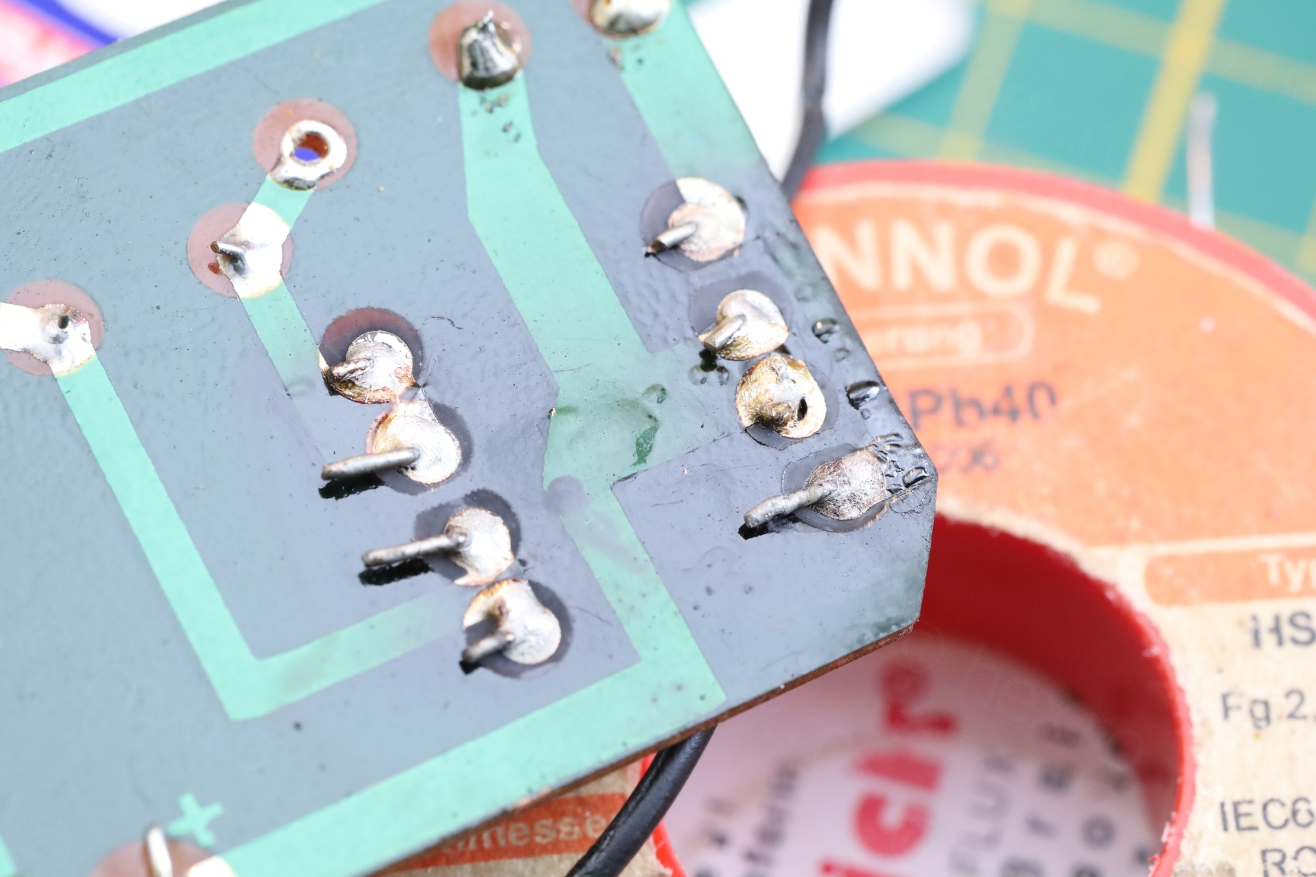
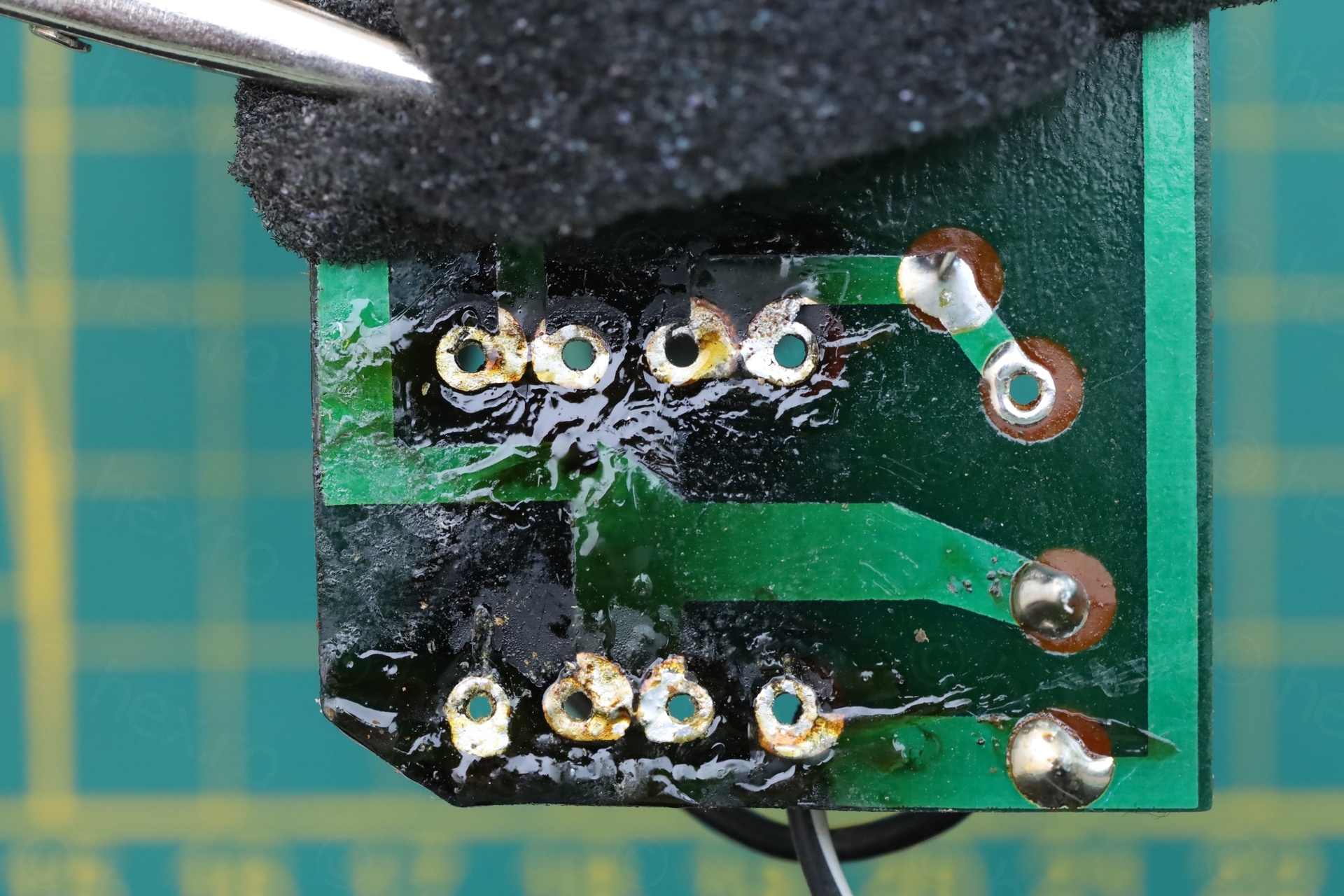
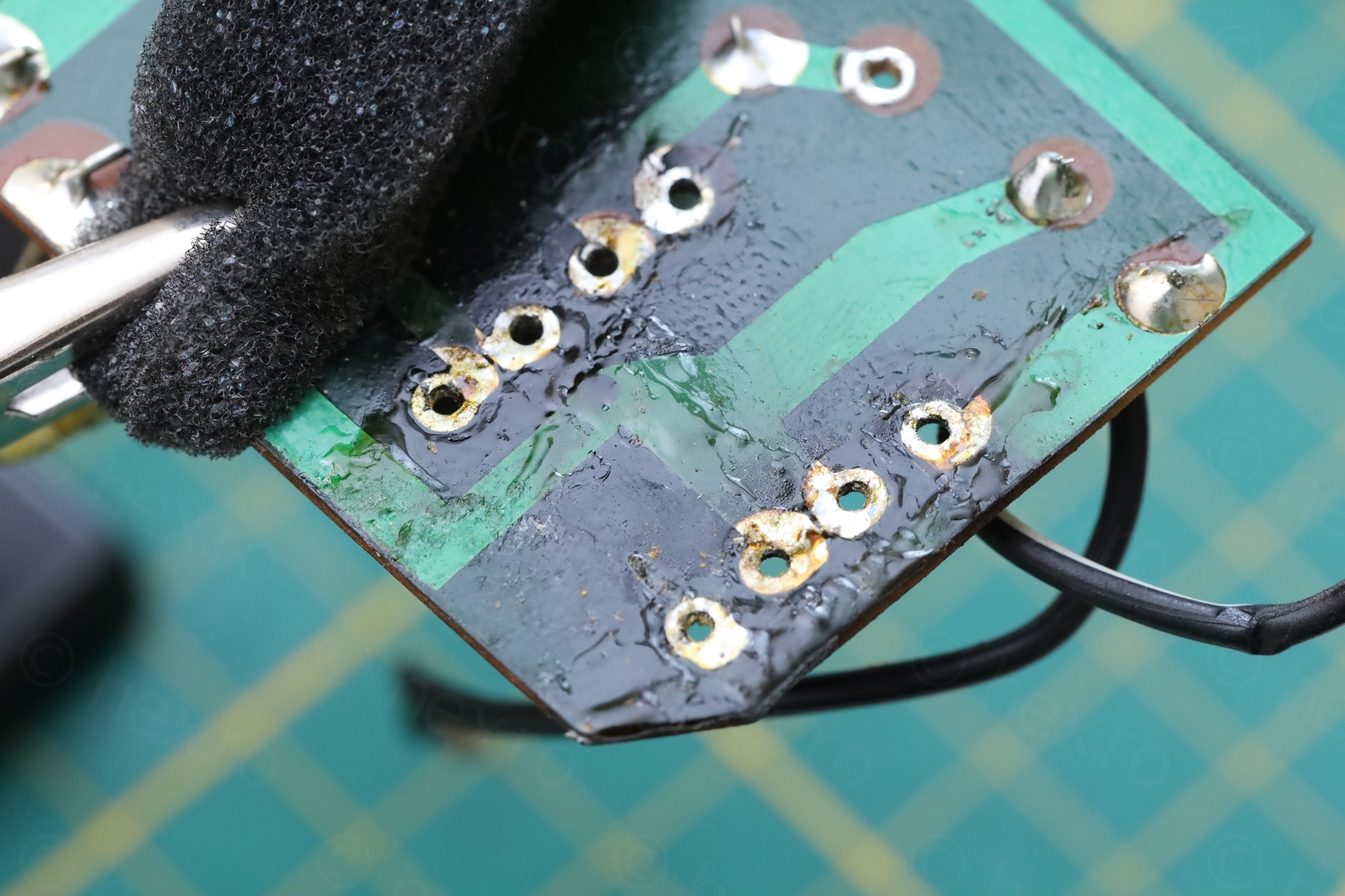
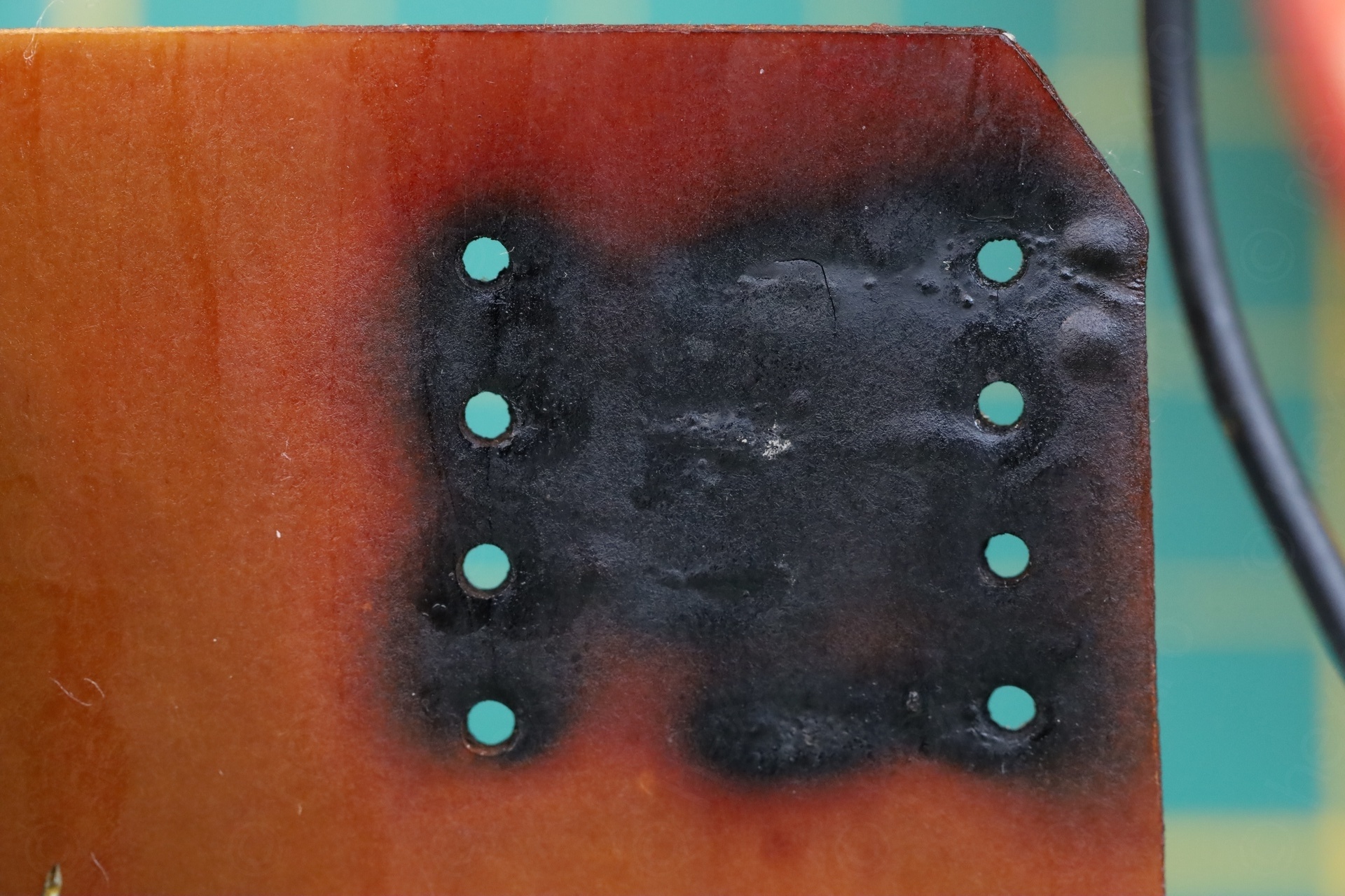
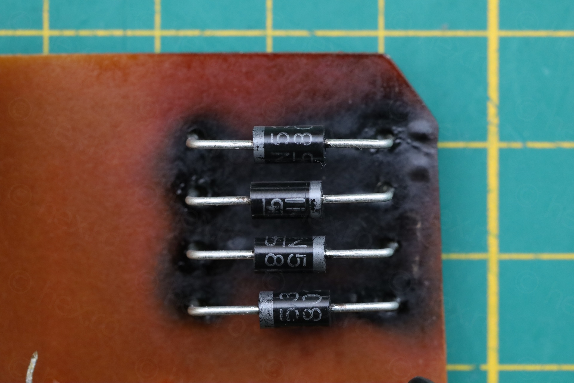
Although there were some issues with the computer board, nothing was shorted and the computer always started. So why would the seller say that it doesn’t work with the original power supply ? I had to take care of it anyway, since the low voltage wires were cut and knotted together. Weord. The power supply has to come apart, this is so fishy I need to see everything. And the horrors of all horrors, it was baked inside:


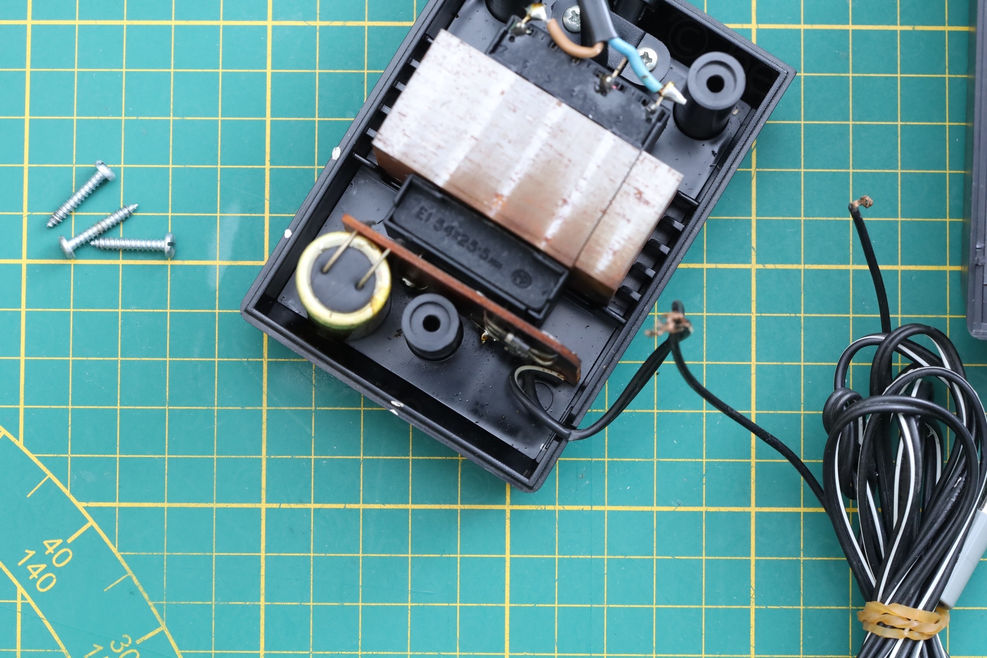
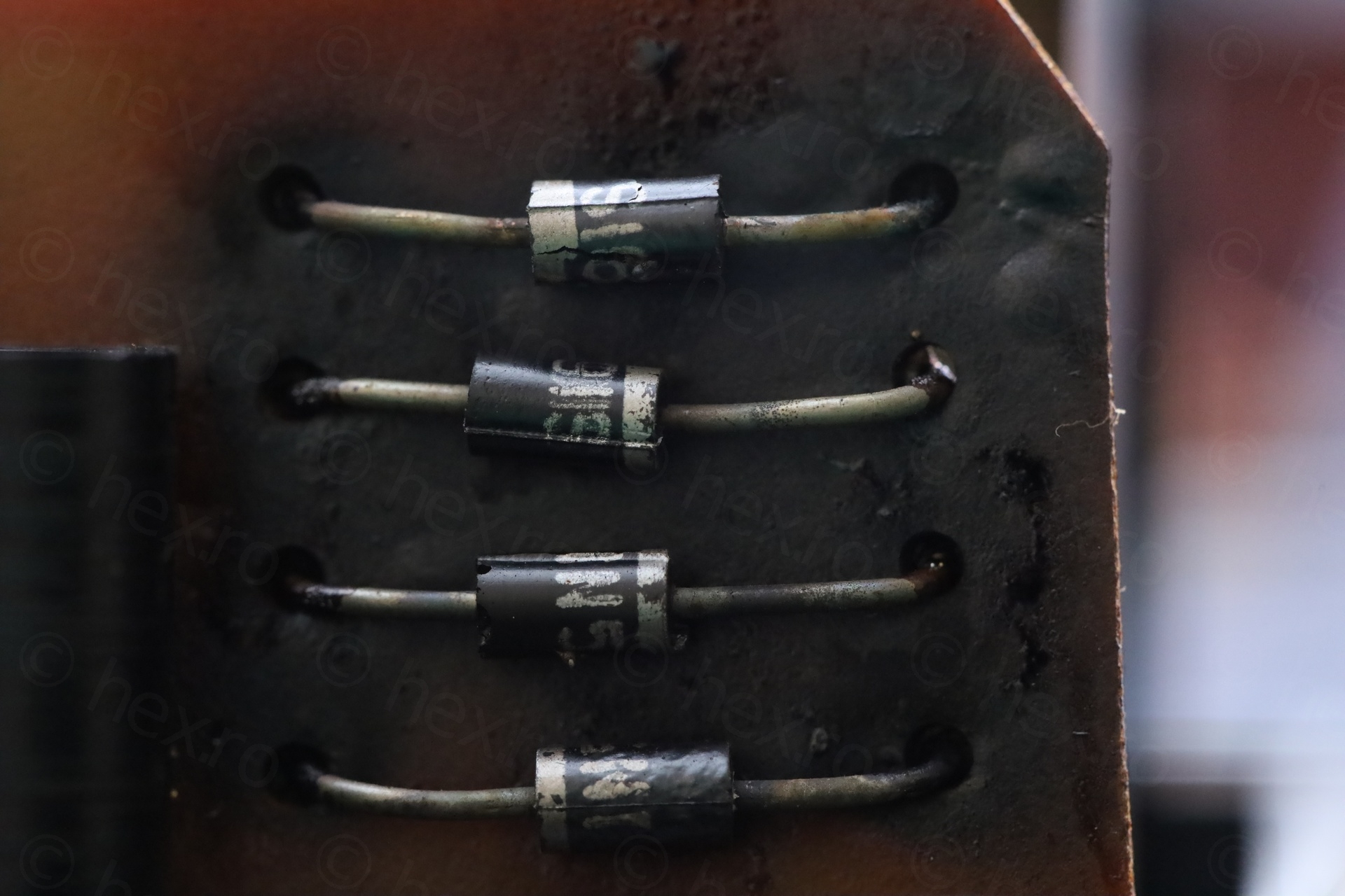
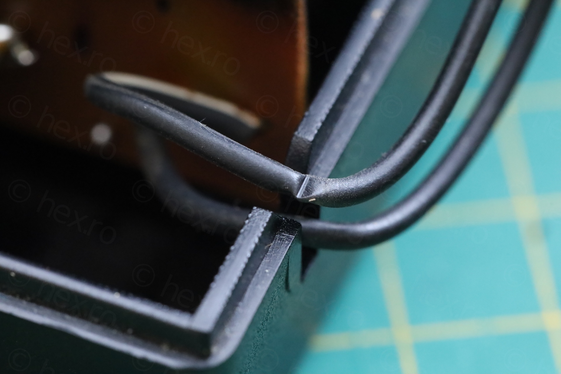
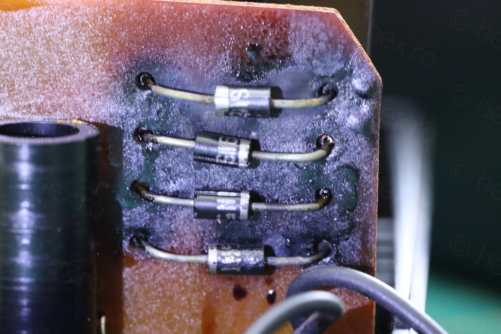

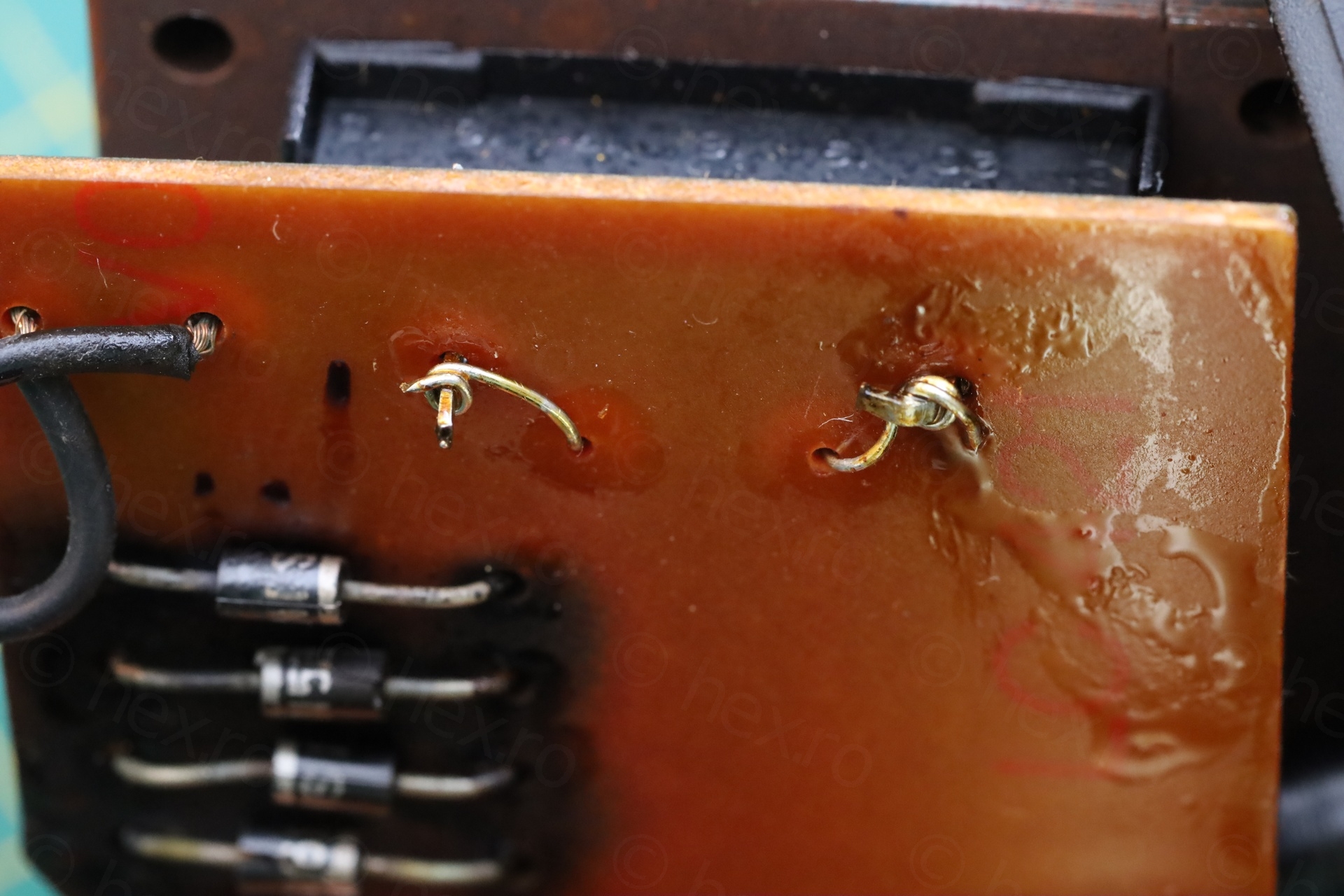
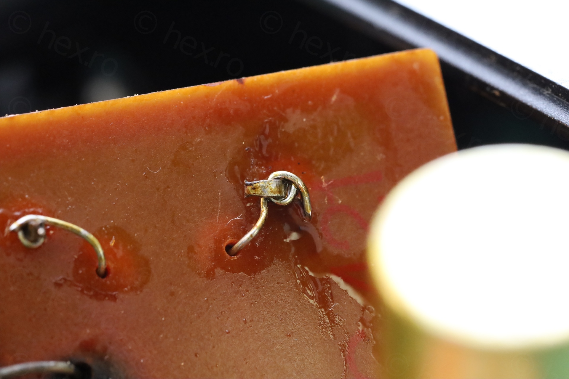
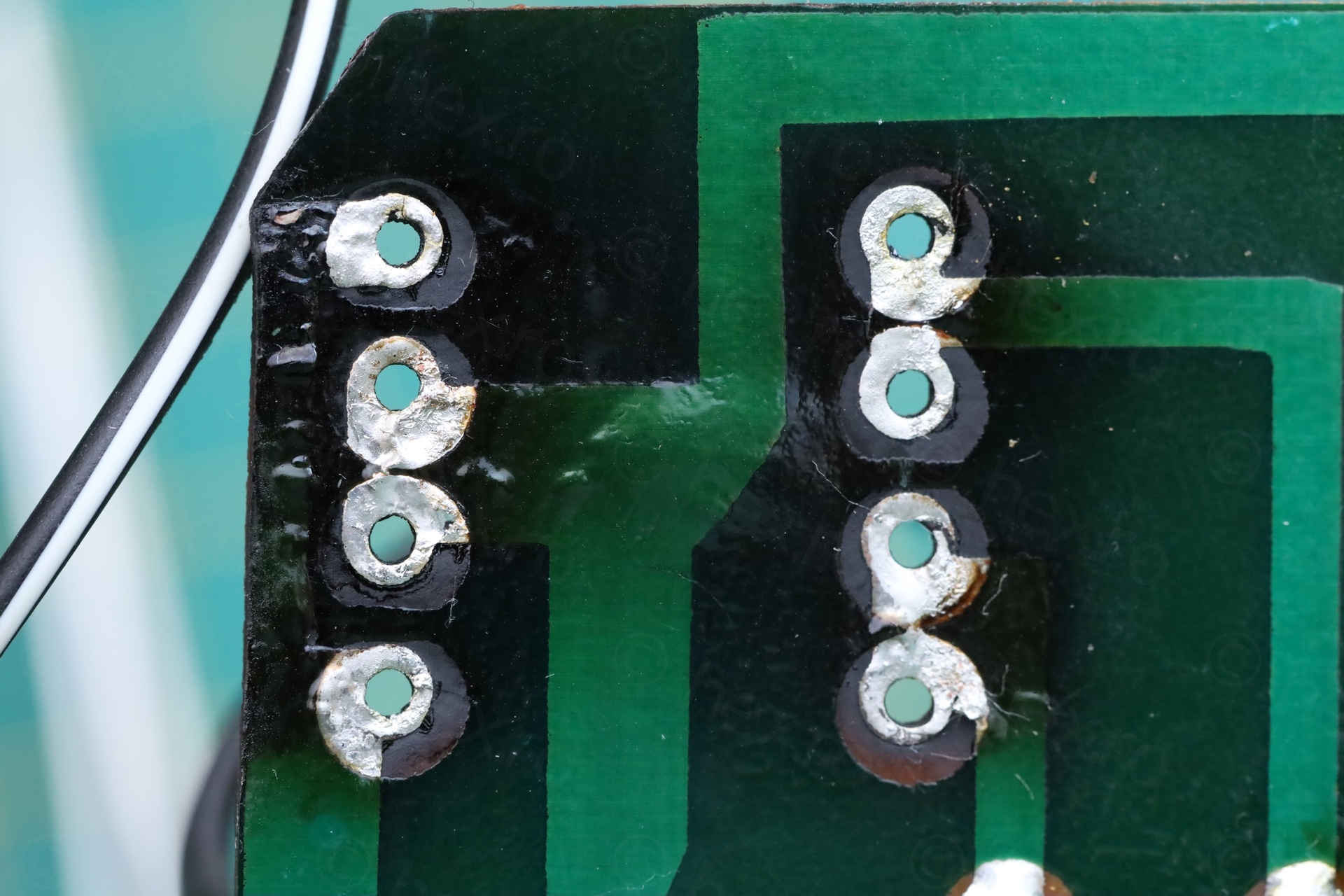
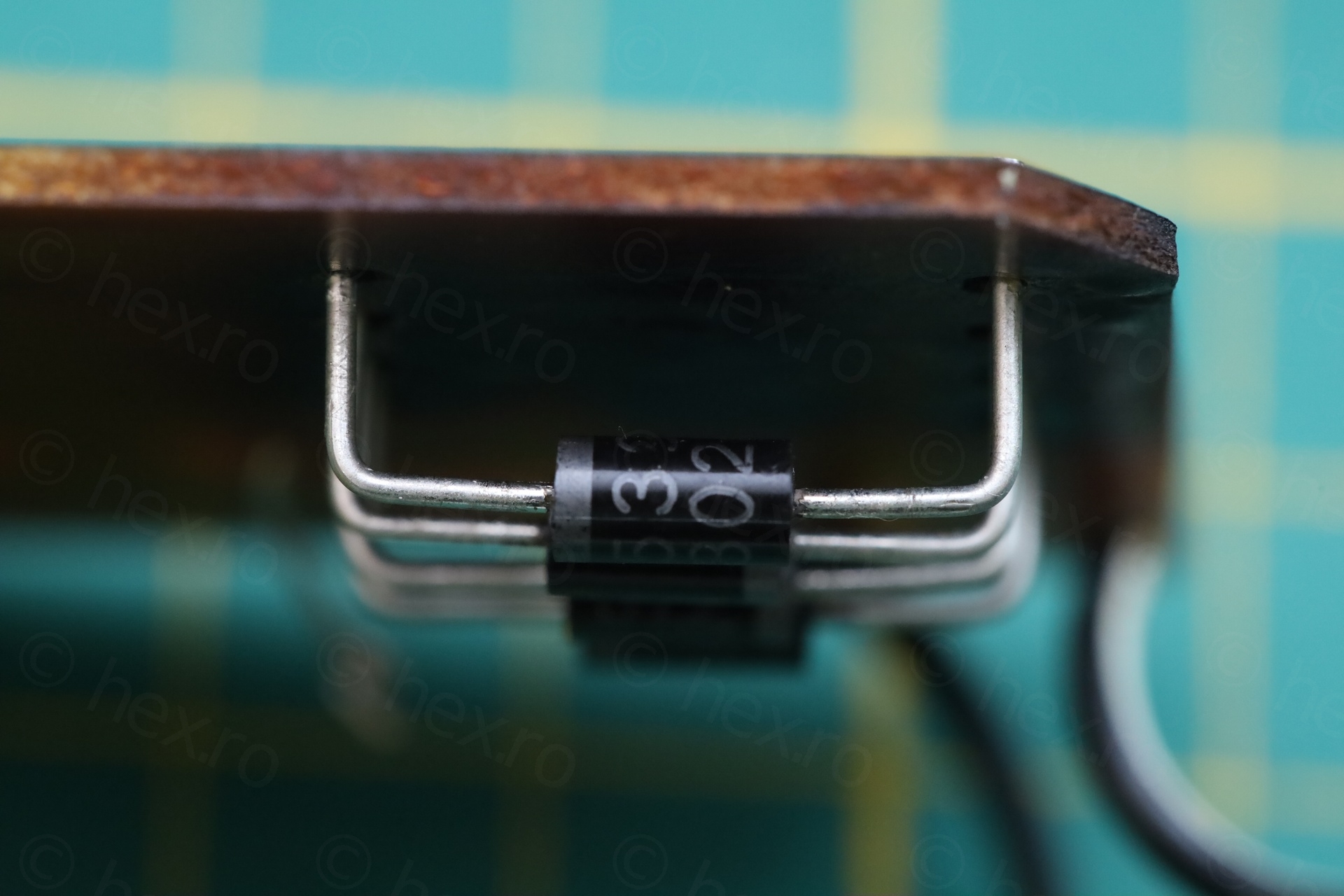
The poor diodes were so burned, they cracked. I proceeded to take the little circuit board out, but you have to first uncurl the transformer wires at the bottom of the board:
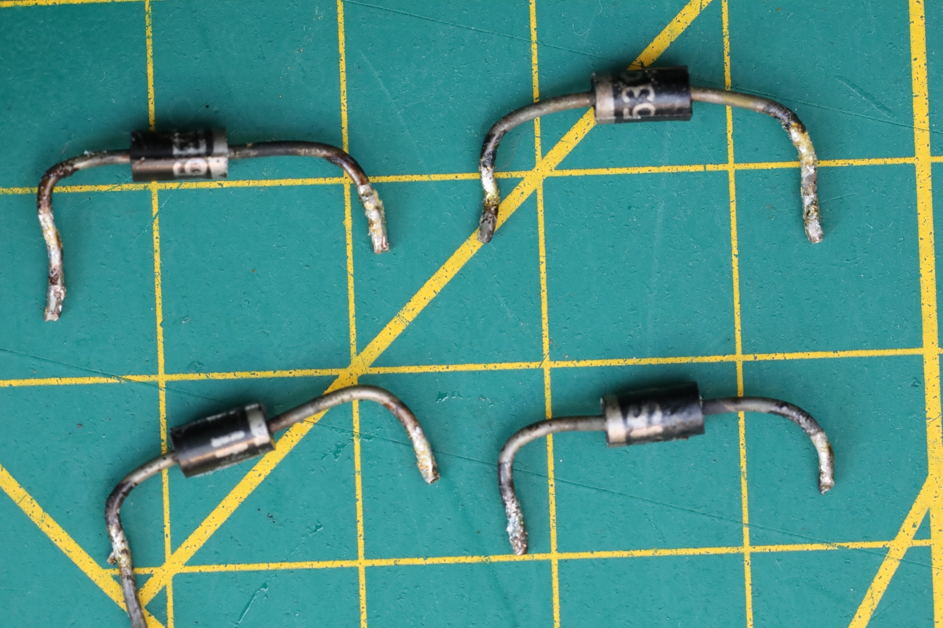
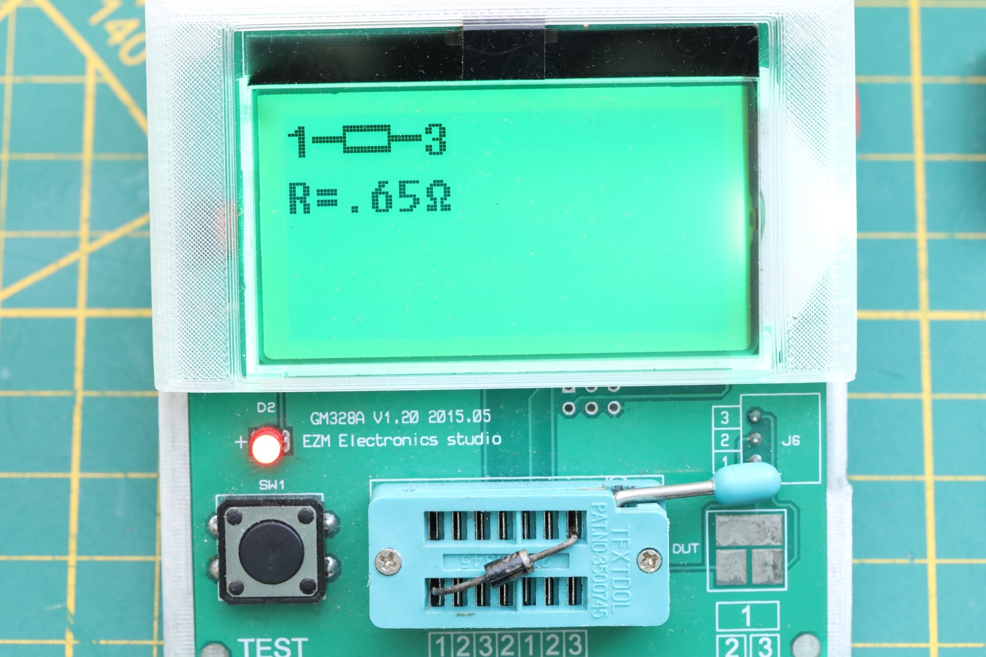
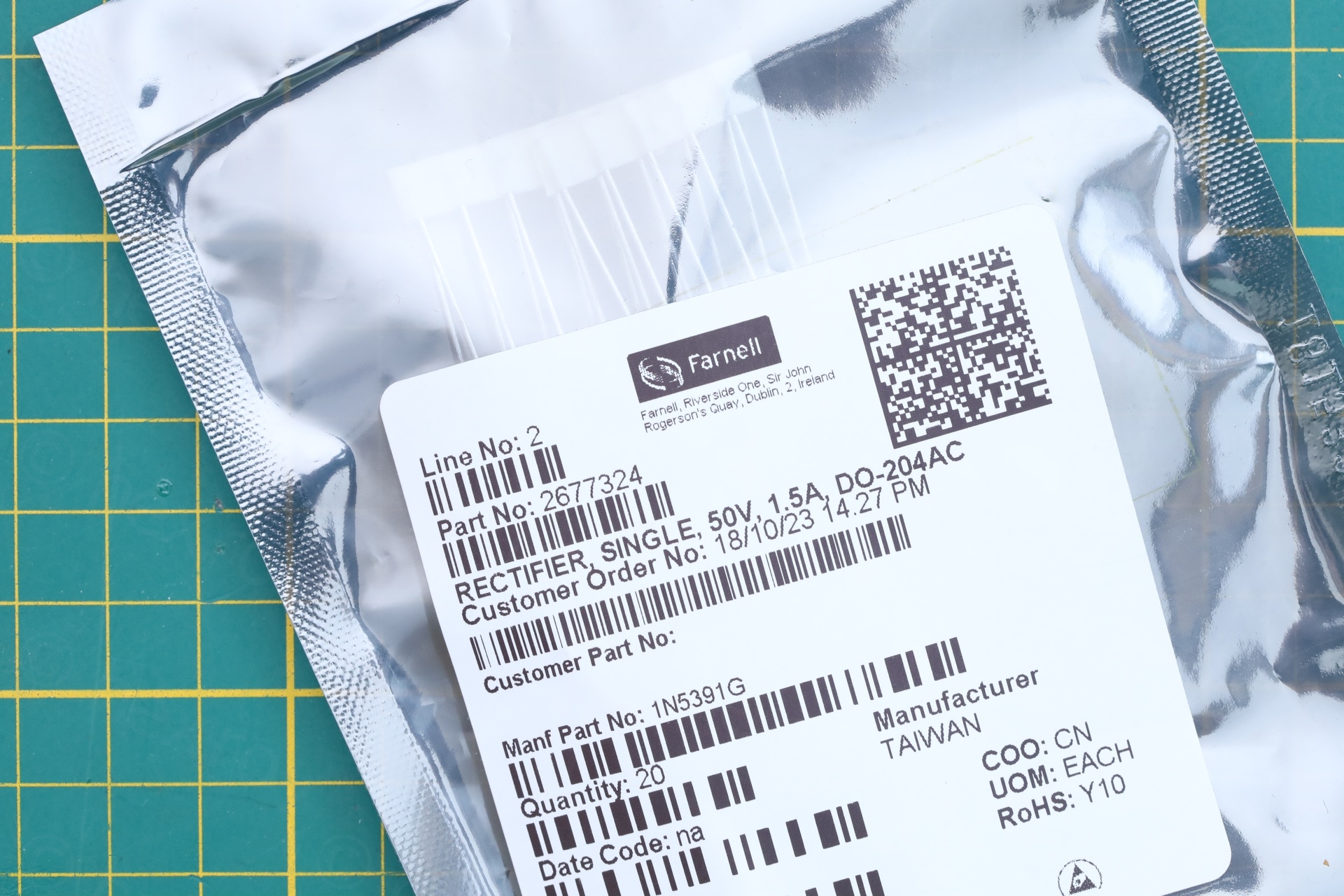
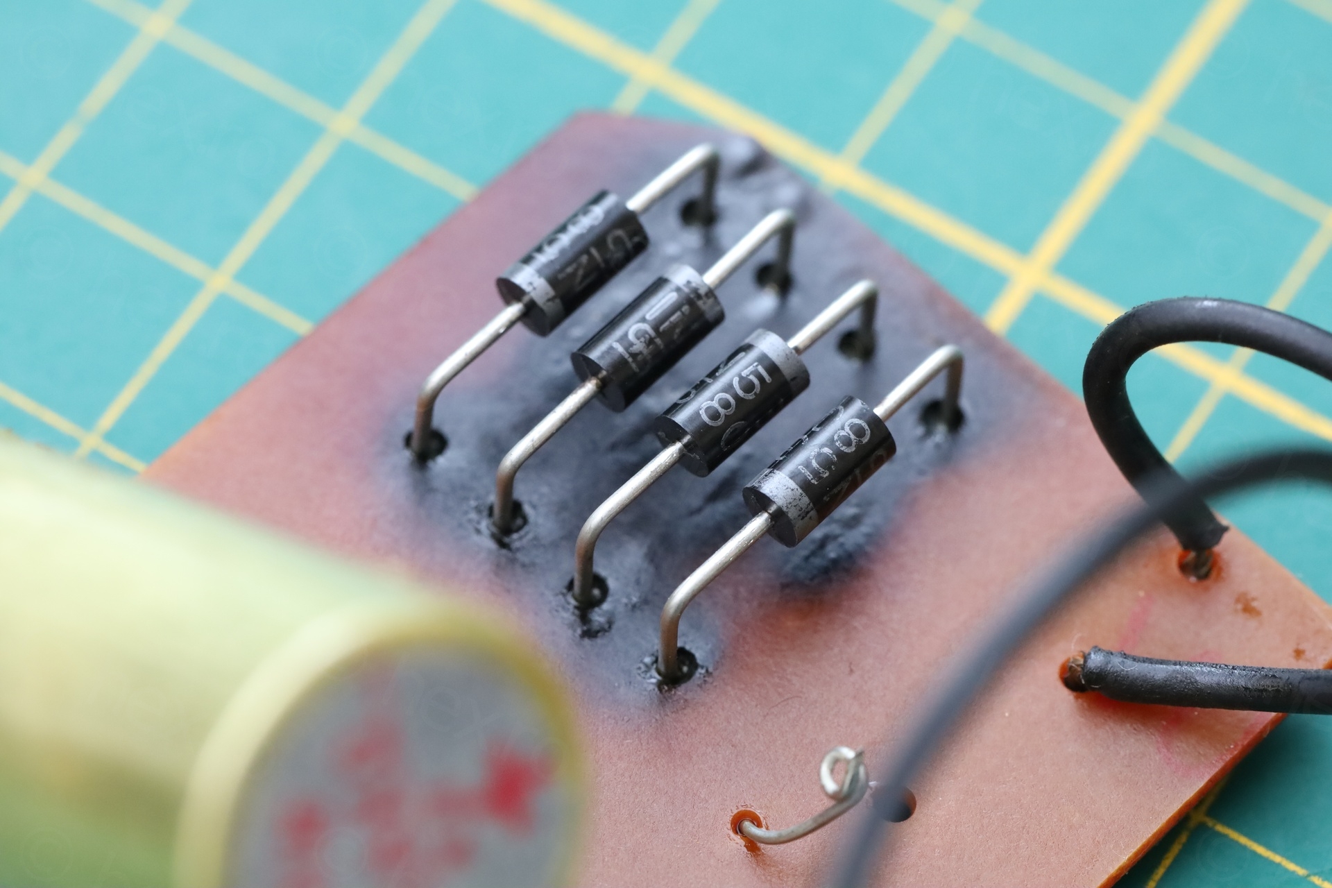
I found the exact same diode replacement model, 1N5391G from Farnell (rated at 1.5A each, 60V). I spaced them out and away from the board, using a piece of wood I had lying around:
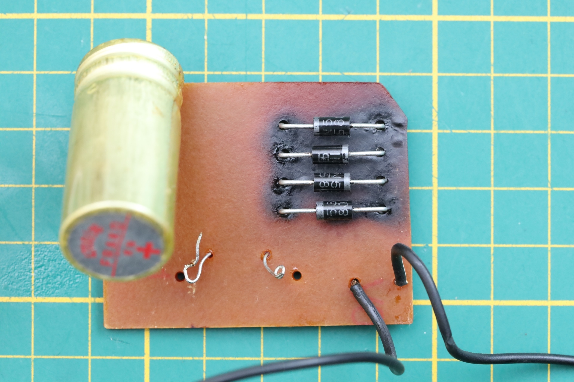
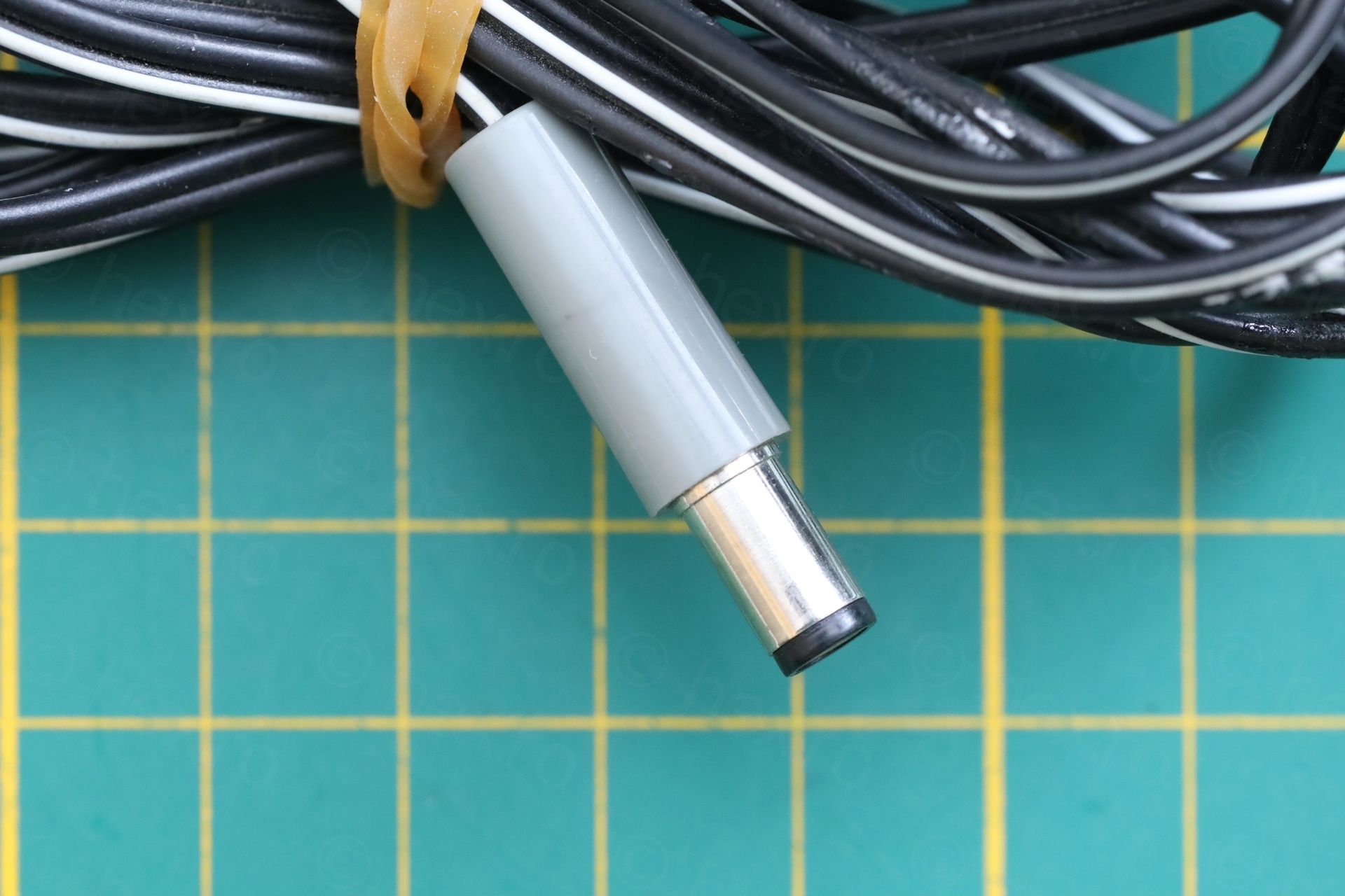
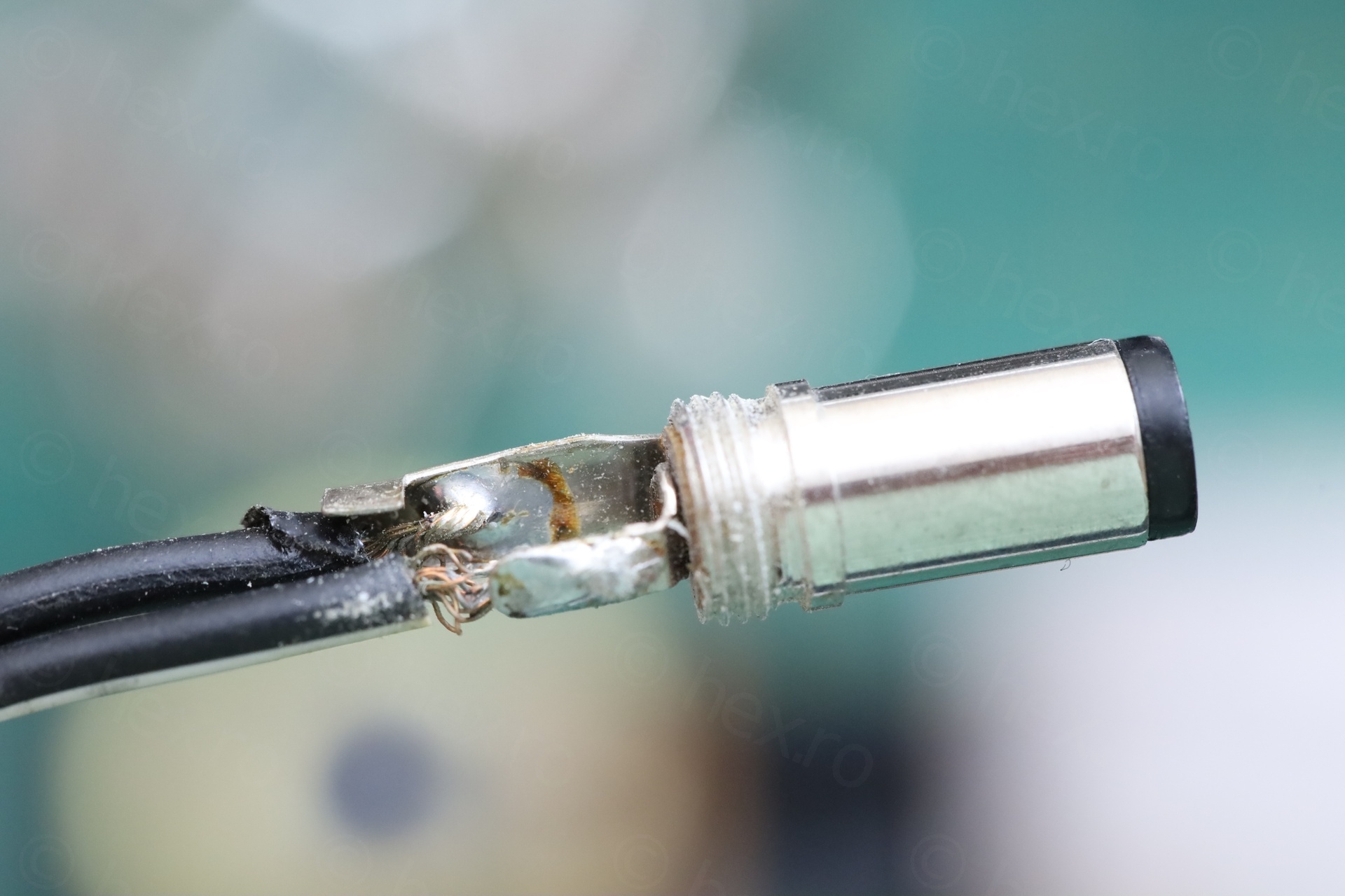
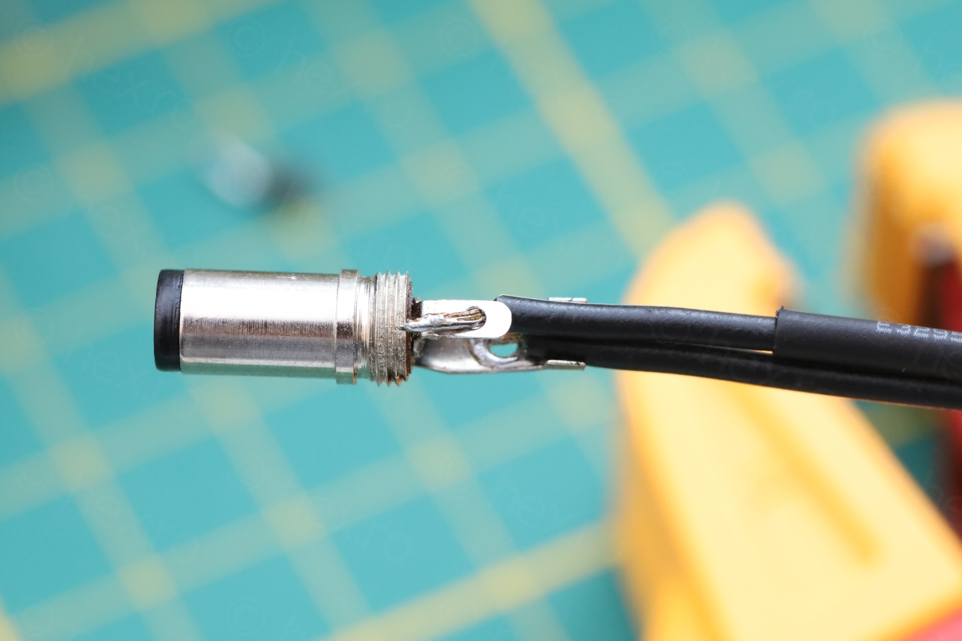
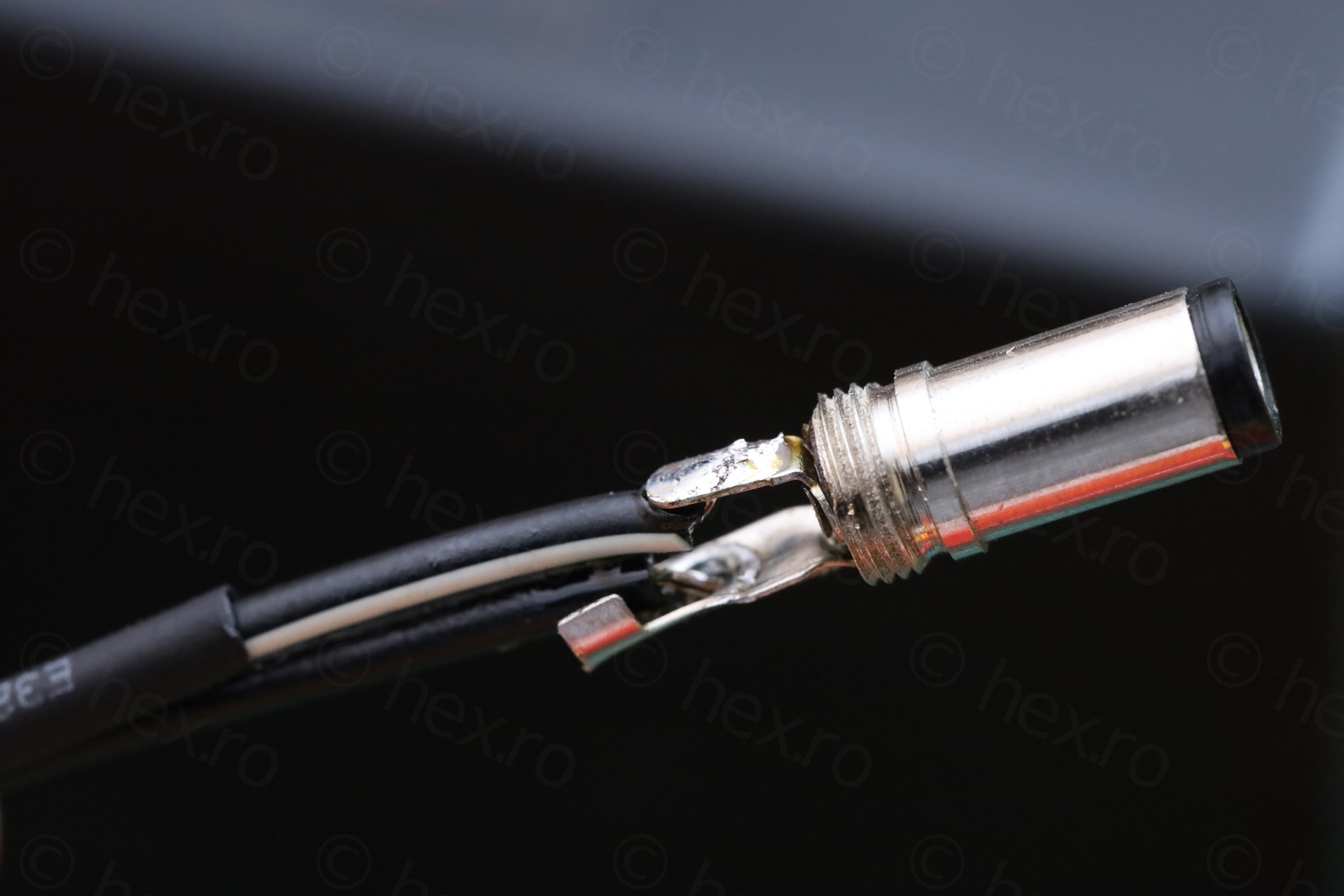
The capacitor still tested good (low ESR) and I decided to keep it. What was puzzling was why was the power supply shorted ? I figured is not the cut wires, it would be too obvious to do that and then plug it in. There was still one thing I didn’t see inside, the power plug.
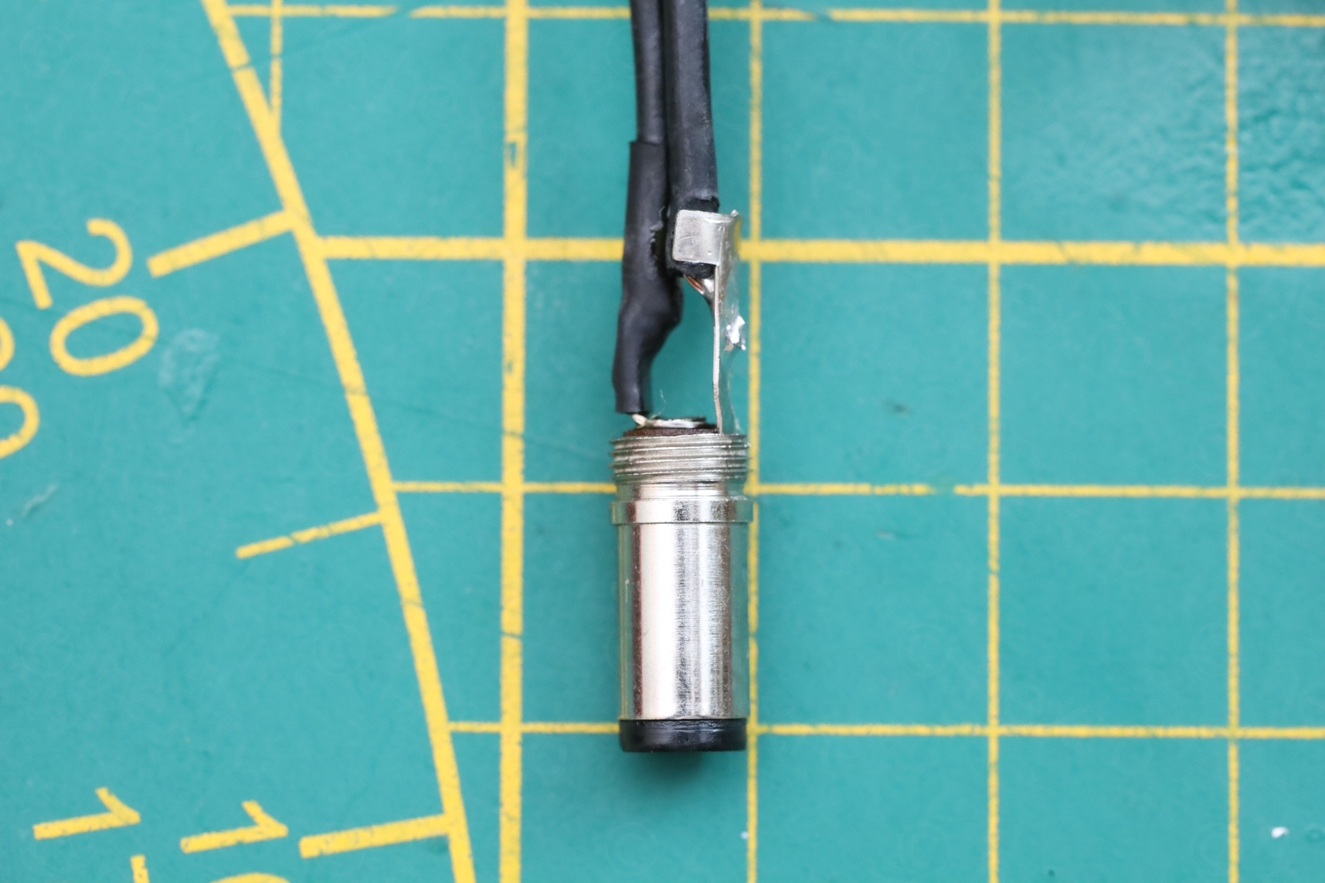
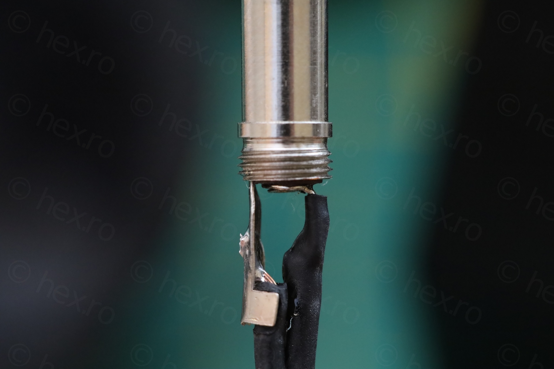
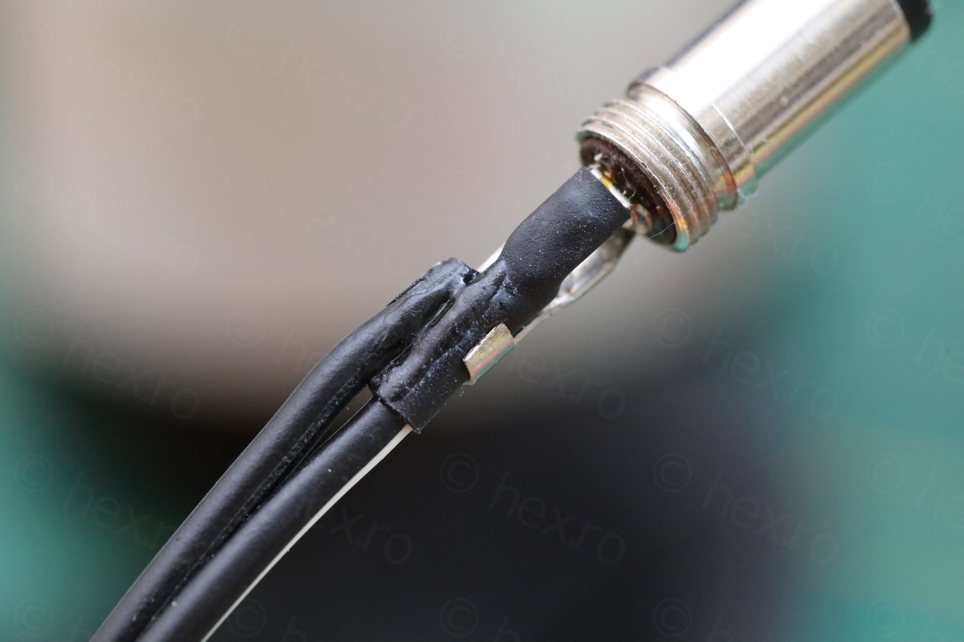
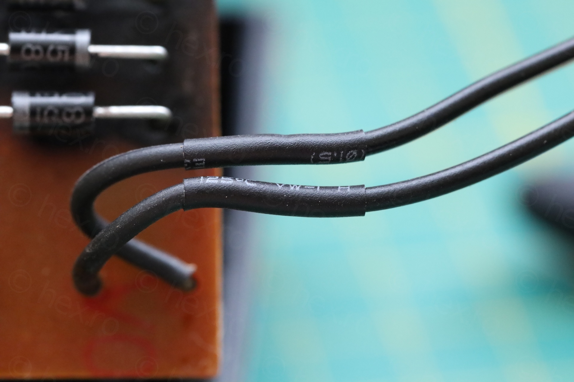
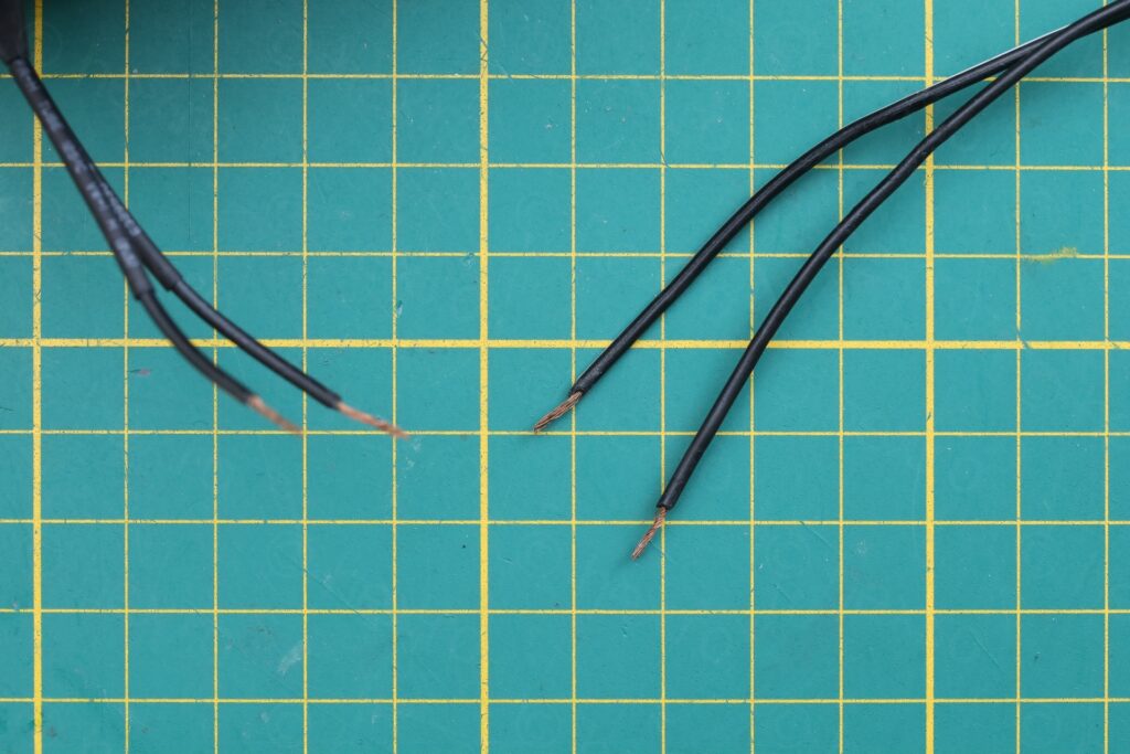
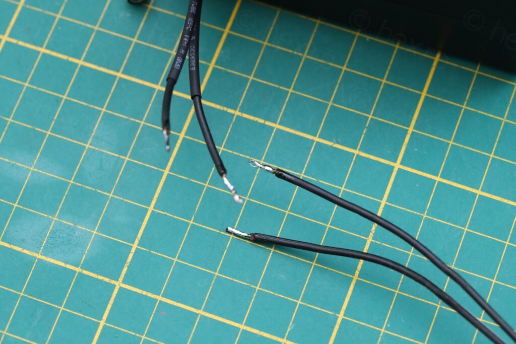
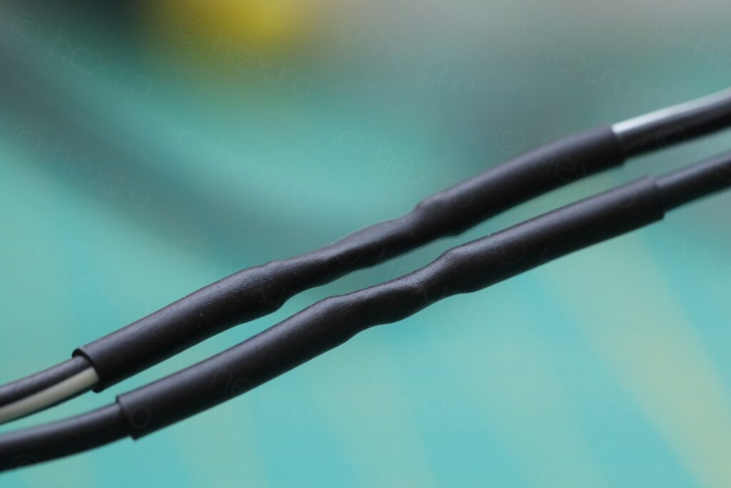
The two wires were not isolated, copper strands were torn and almost touching. Most likely they touched when the gray shroud was screwed over them. De-soldered the wires, cleaned, used shrink wrap insulation (and a drop of Superglue on the two shrink wraps to prevent them from moving):
Euro 1400 Power Supply Strain Relief
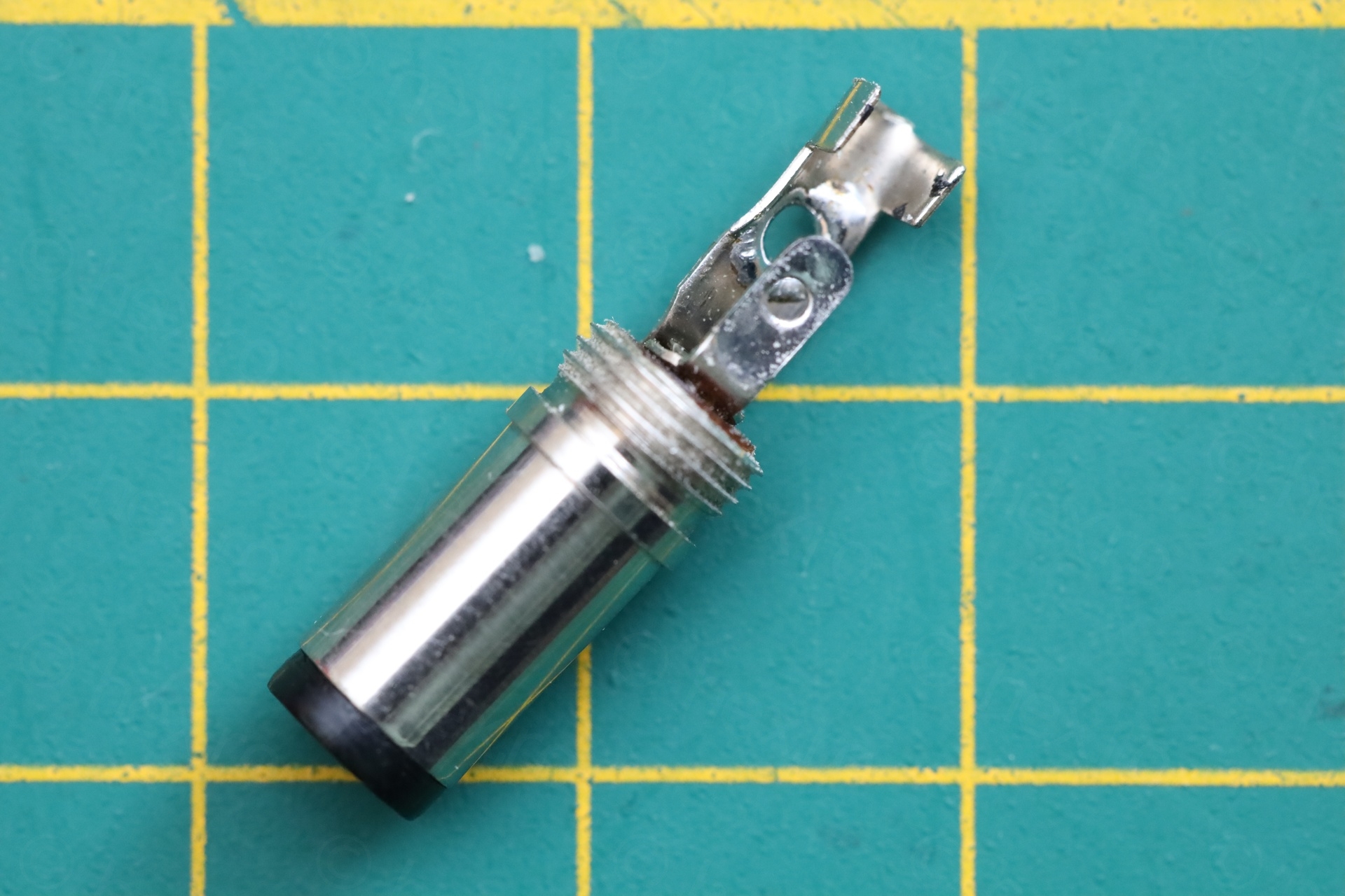
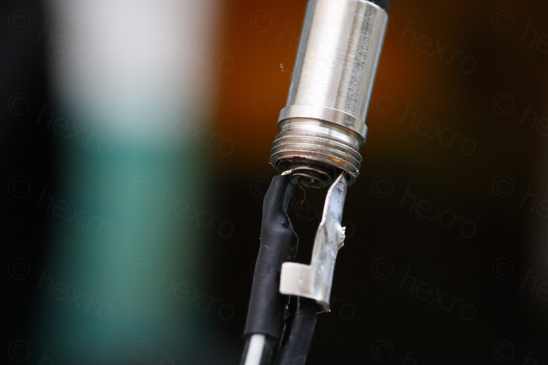
The trouble was also that the strain relief was gone. I figure somebody has already replaced this wires. I also could not find anything similar to buy, so I had to 3D print one:
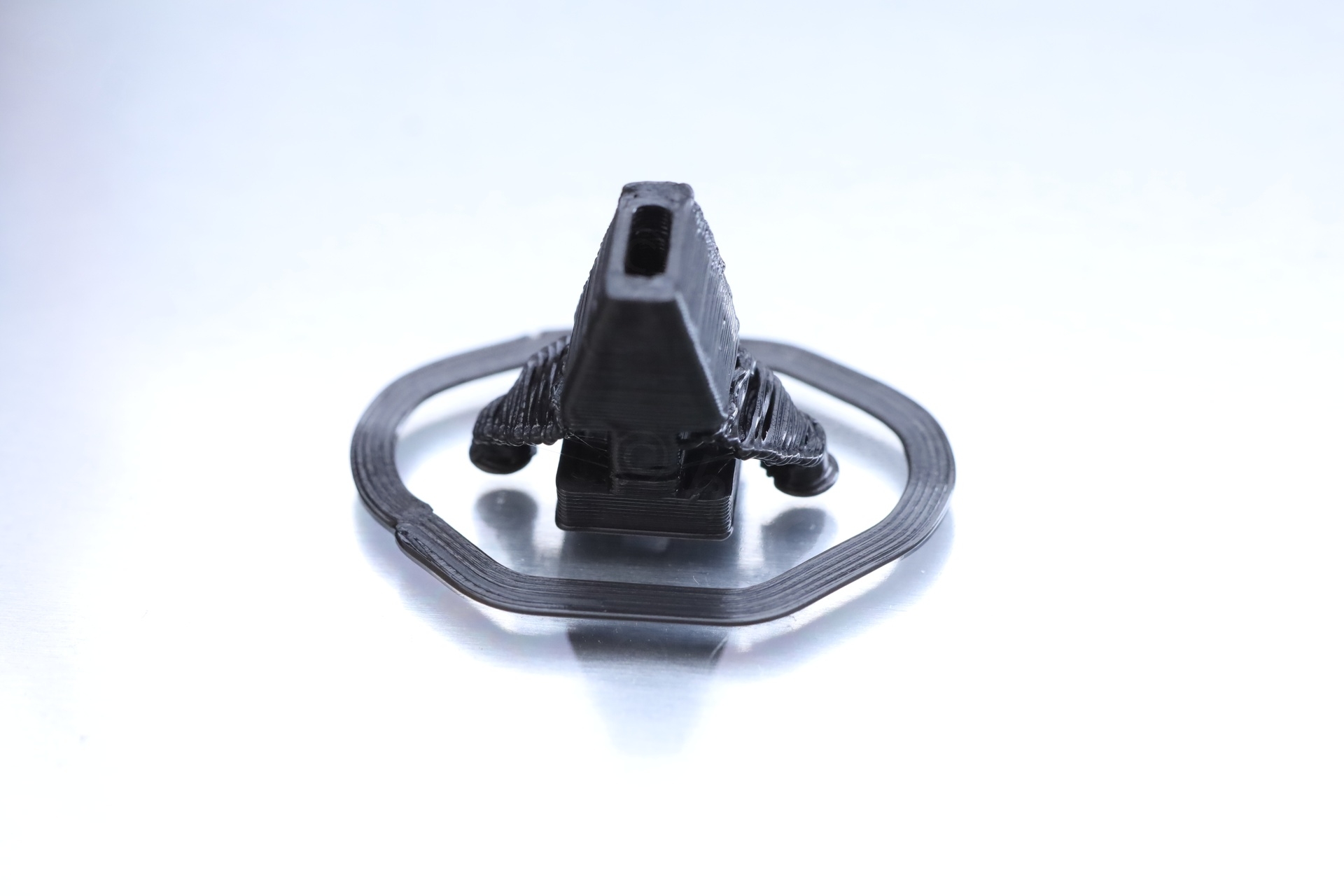
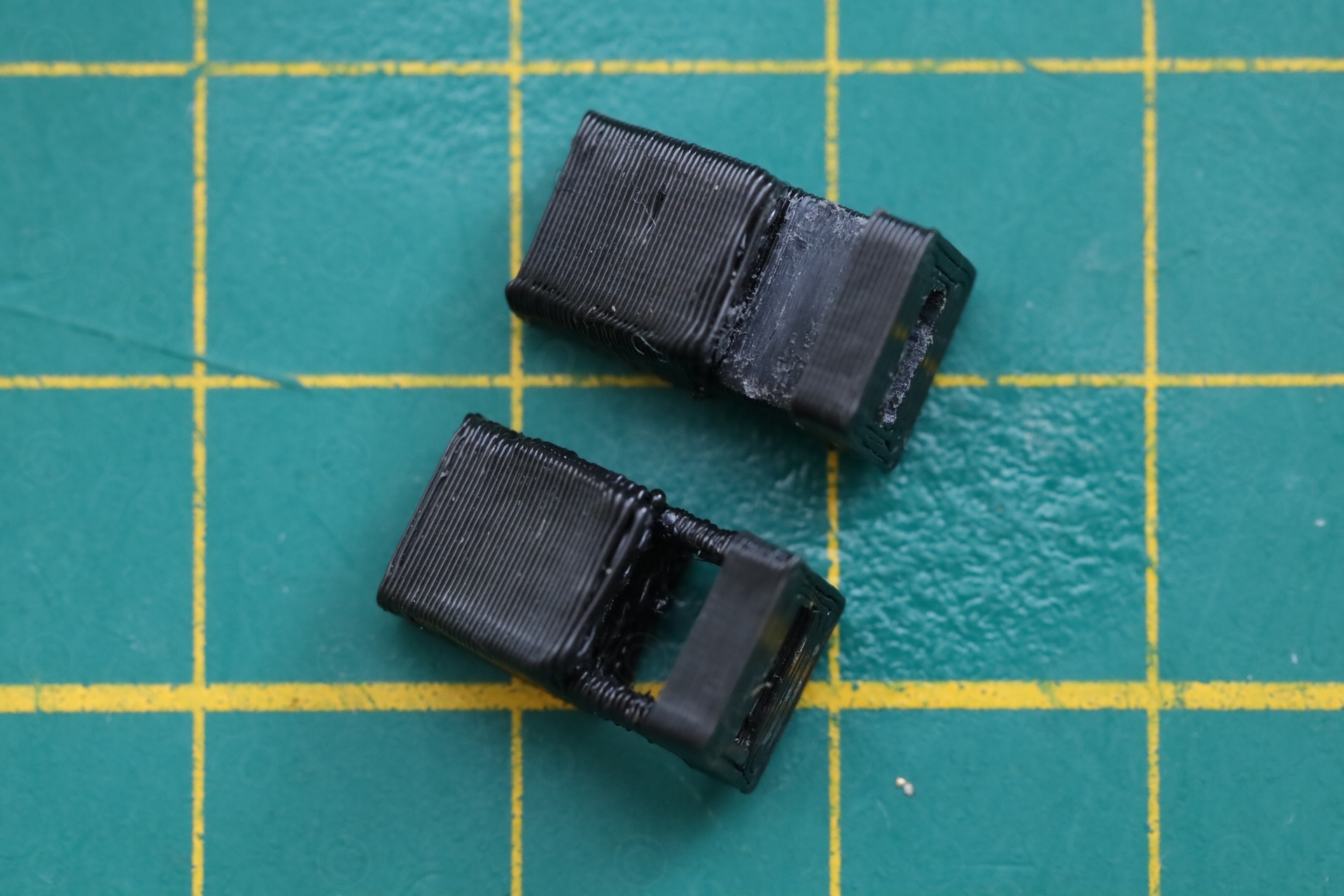
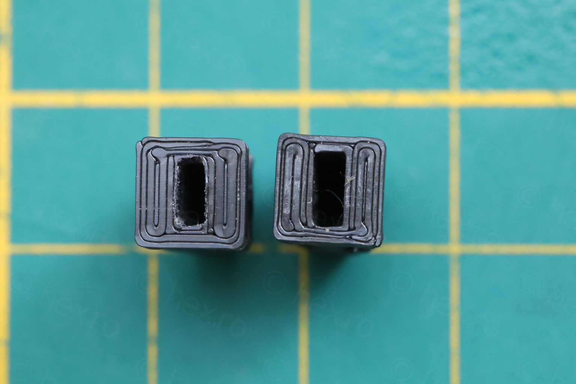
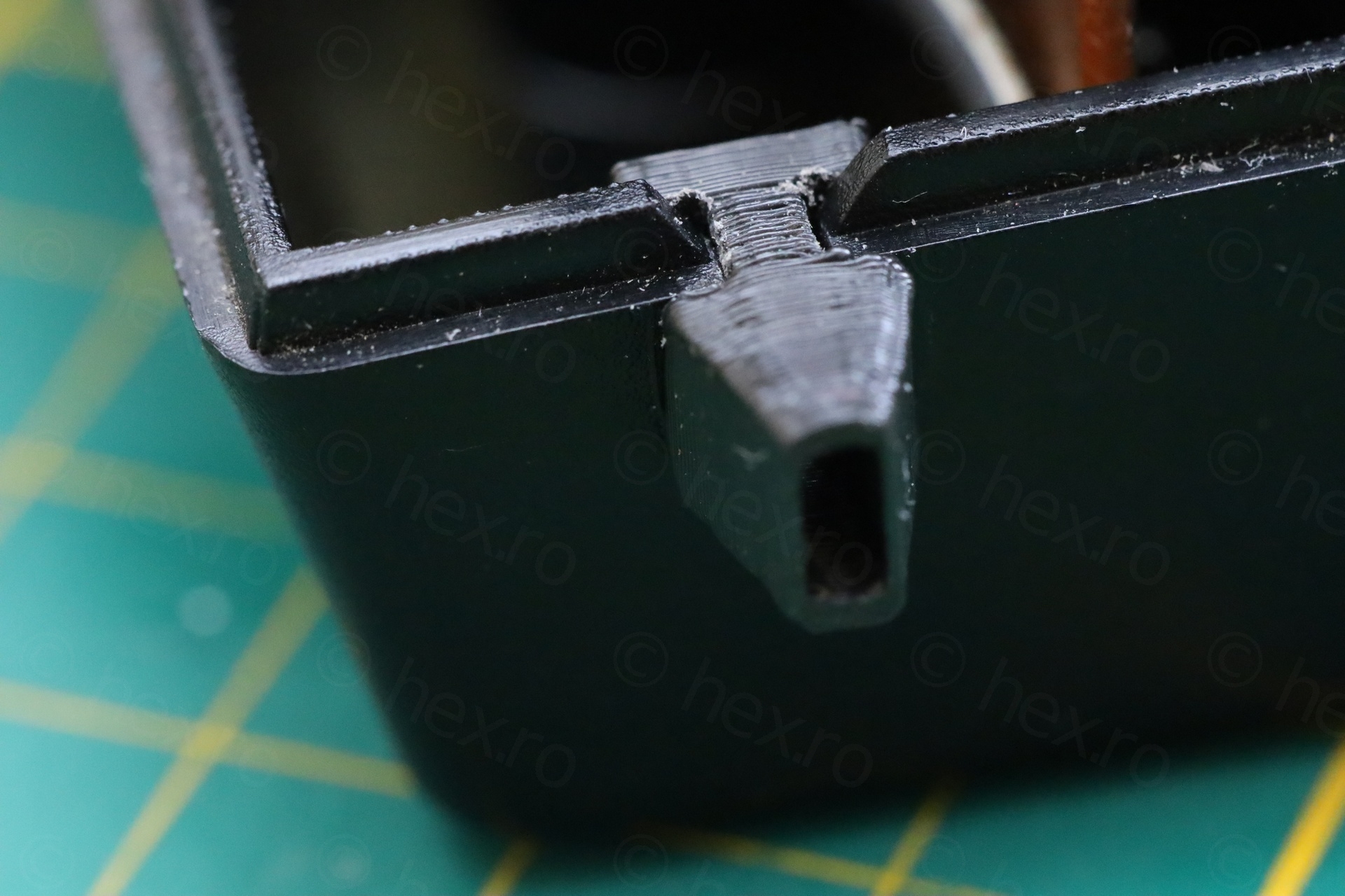
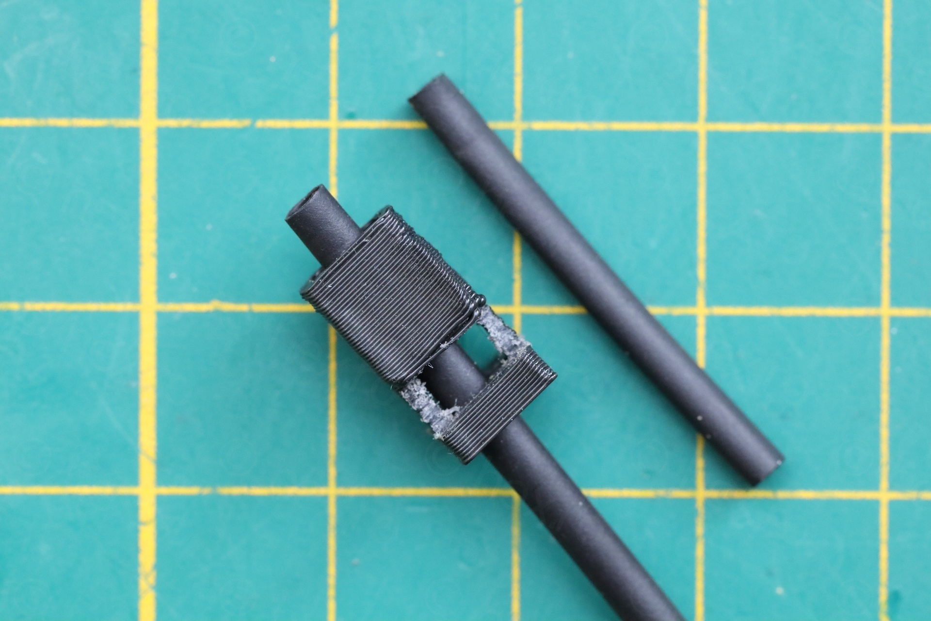
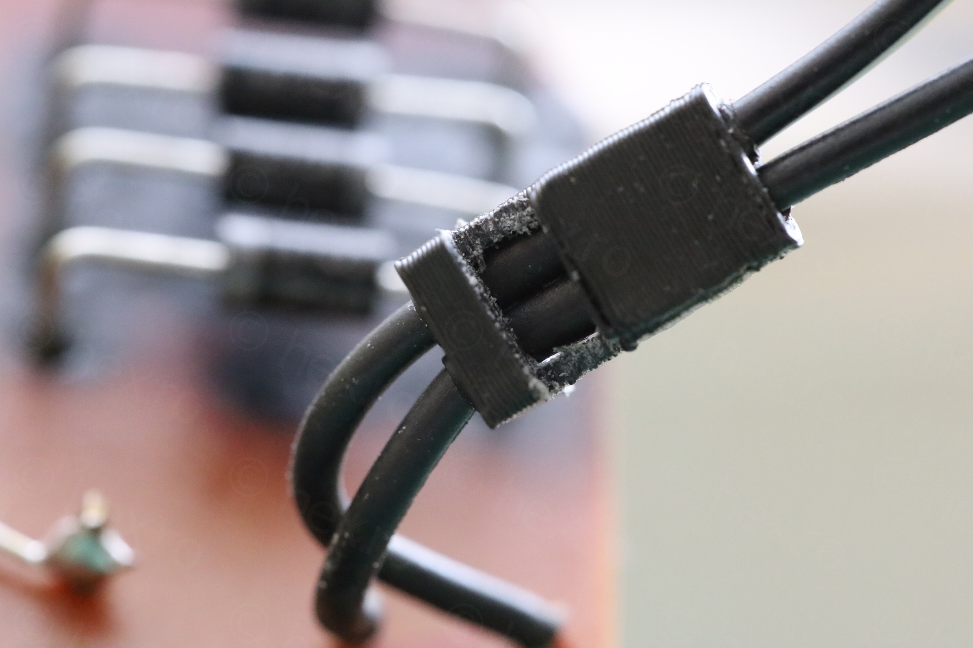
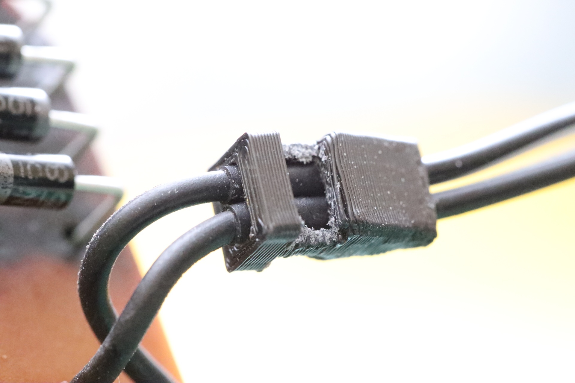
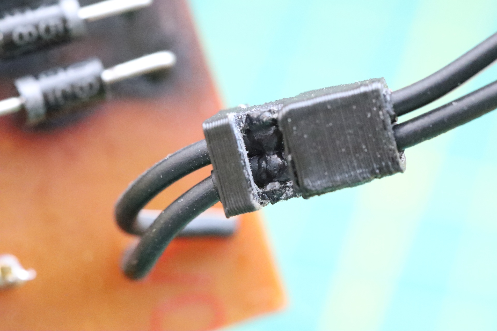
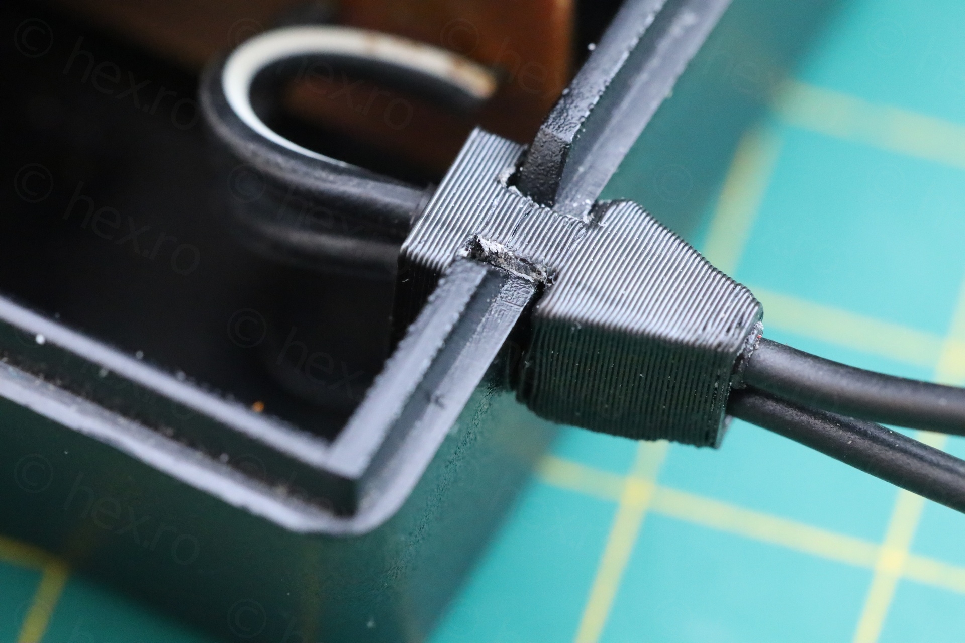
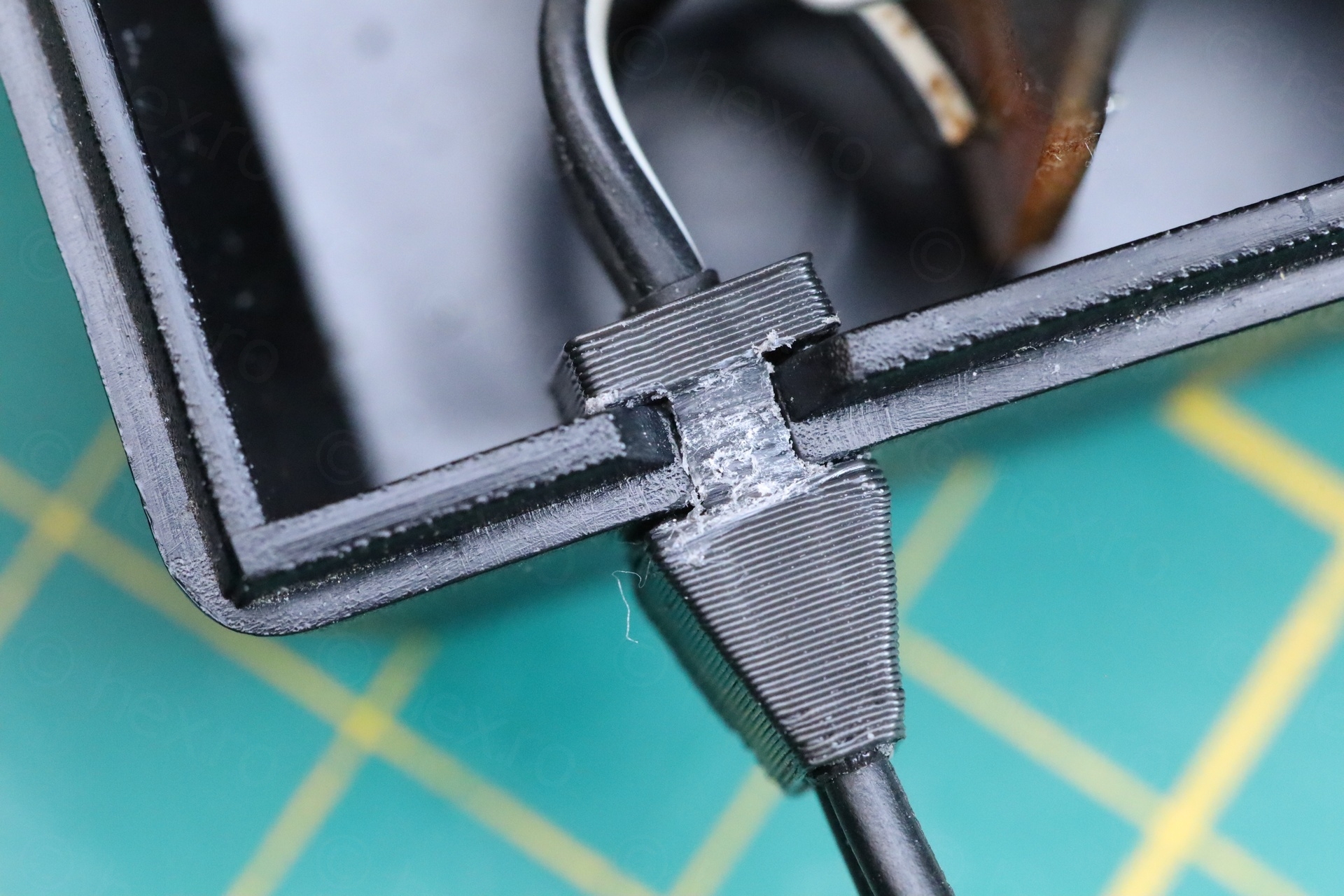
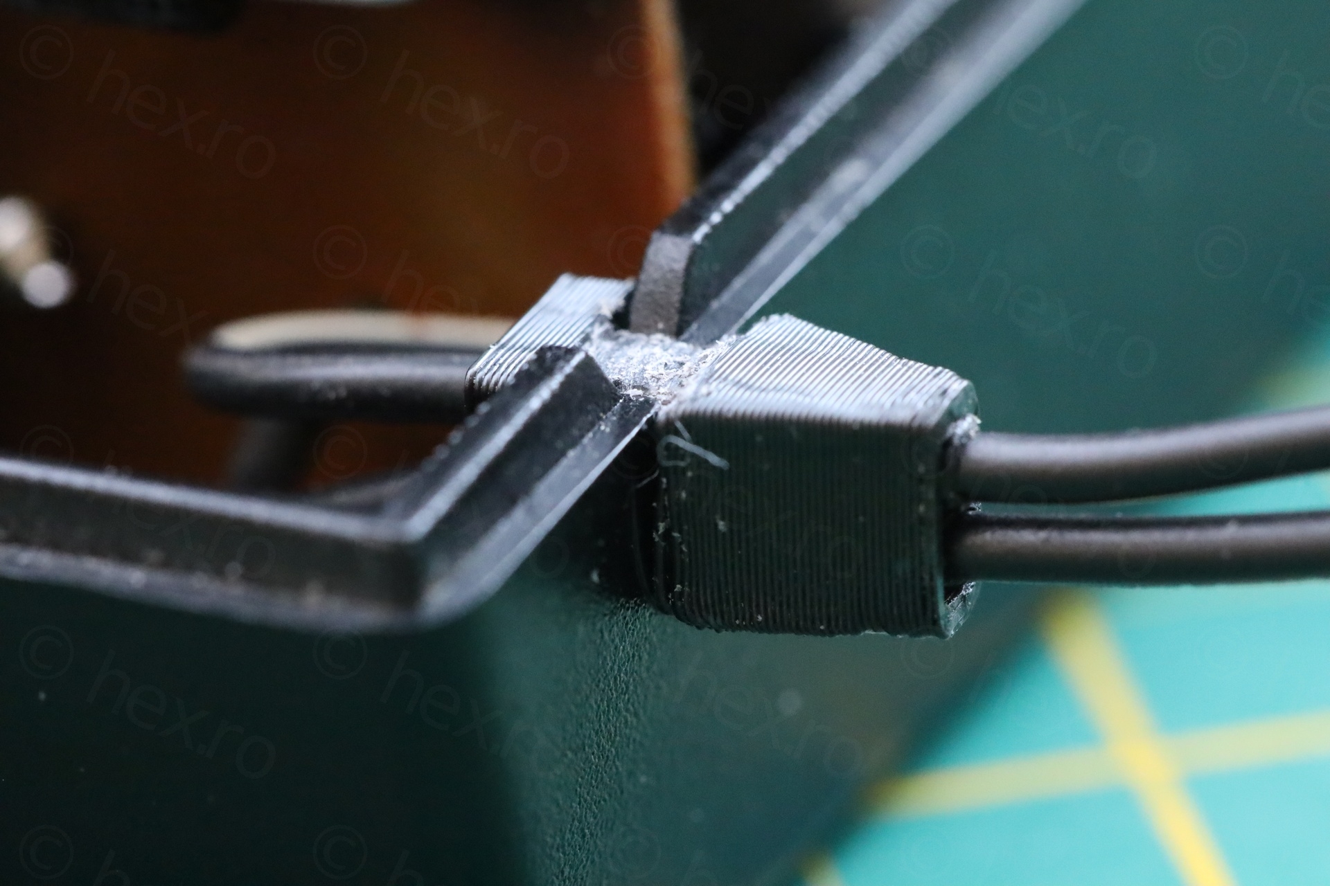
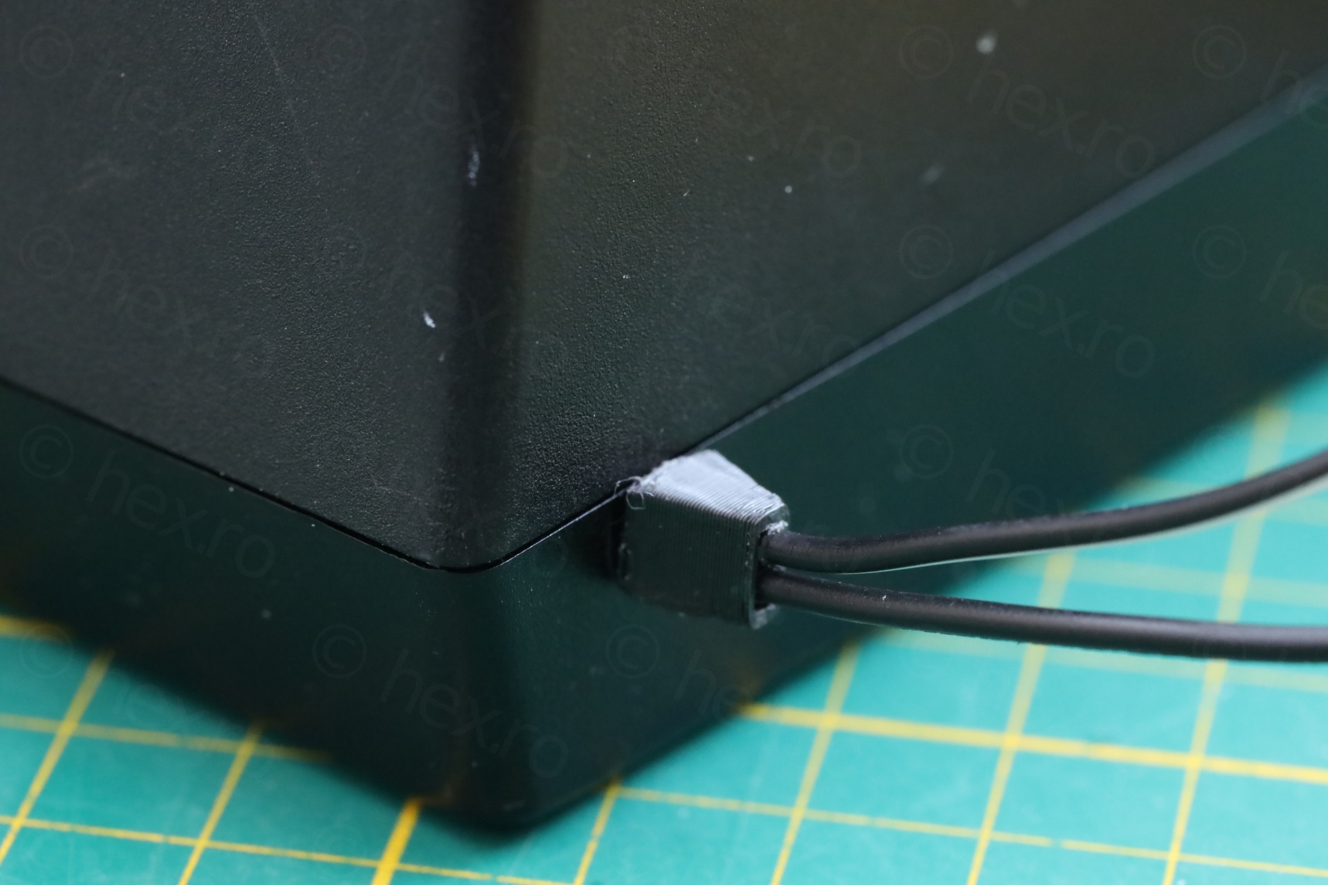
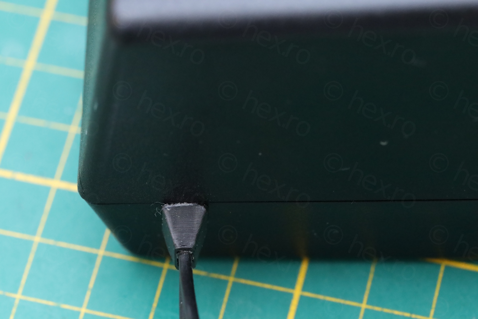
The 3D print was difficult. Too tiny, I could not print any smaller so I had to file gently so that I don’t break the poor structure. Of course I did break some. The goal was to make room enough so that the wires surrounded by shrink wrap would fit through. I super glued the shrink wrap to the 3D print, to give more stability. Waited until everything dried and put everything back as you see above.
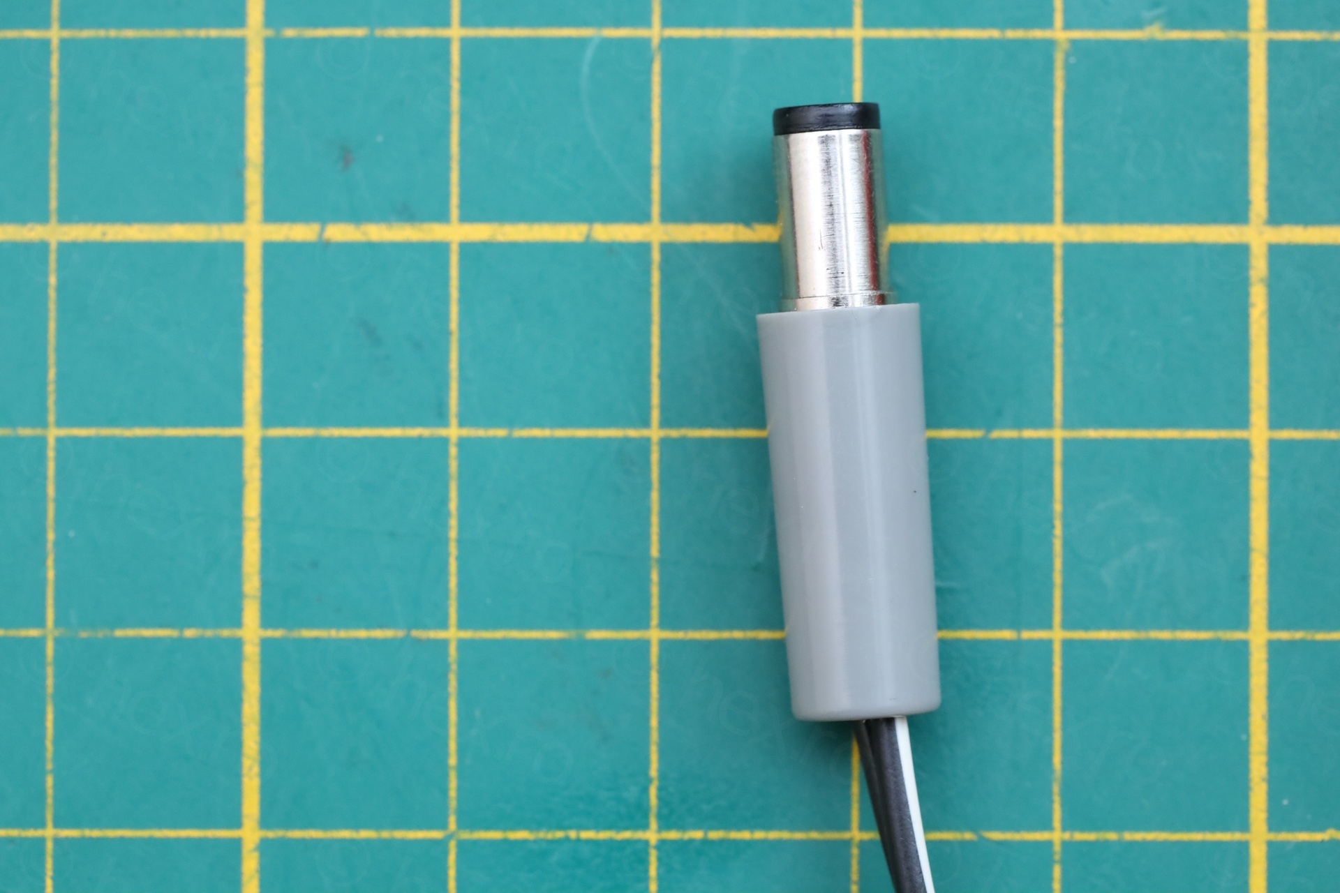
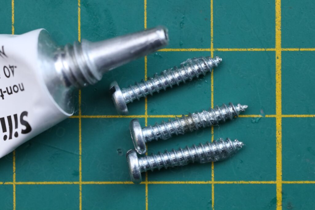
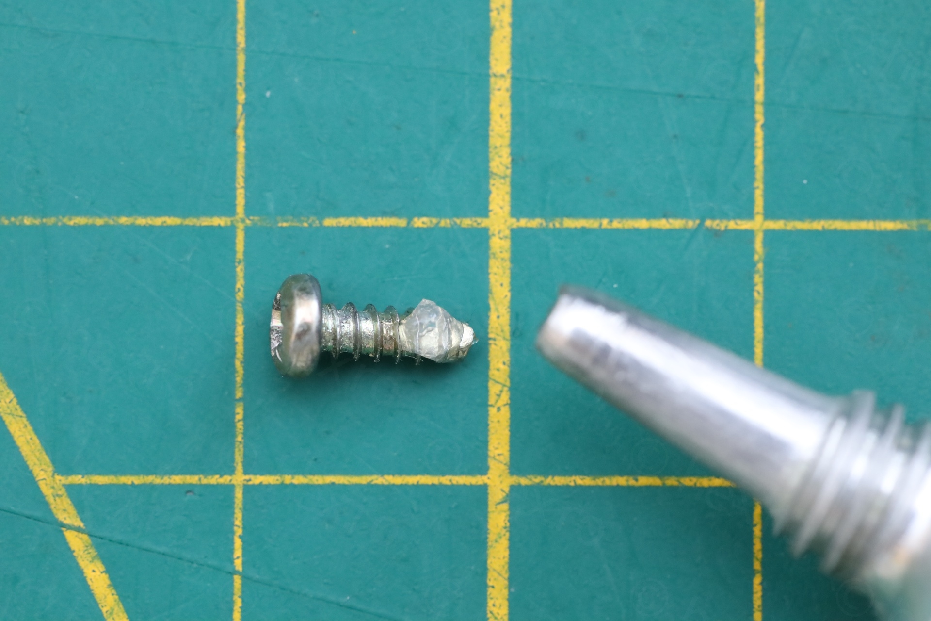
Since the wire was cut in different place, I had to also solder that and protect that part with additional shrink wrap. To put the power supply together, I added a bit of silicone grease on the screws:
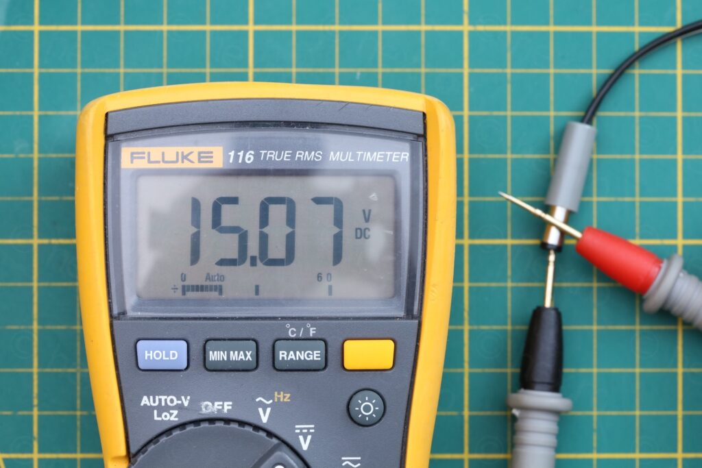
It produces 15.07V unloaded. The transformer itself produces 11.8V AC RMS (I measured it before I connected the small circuit board back).
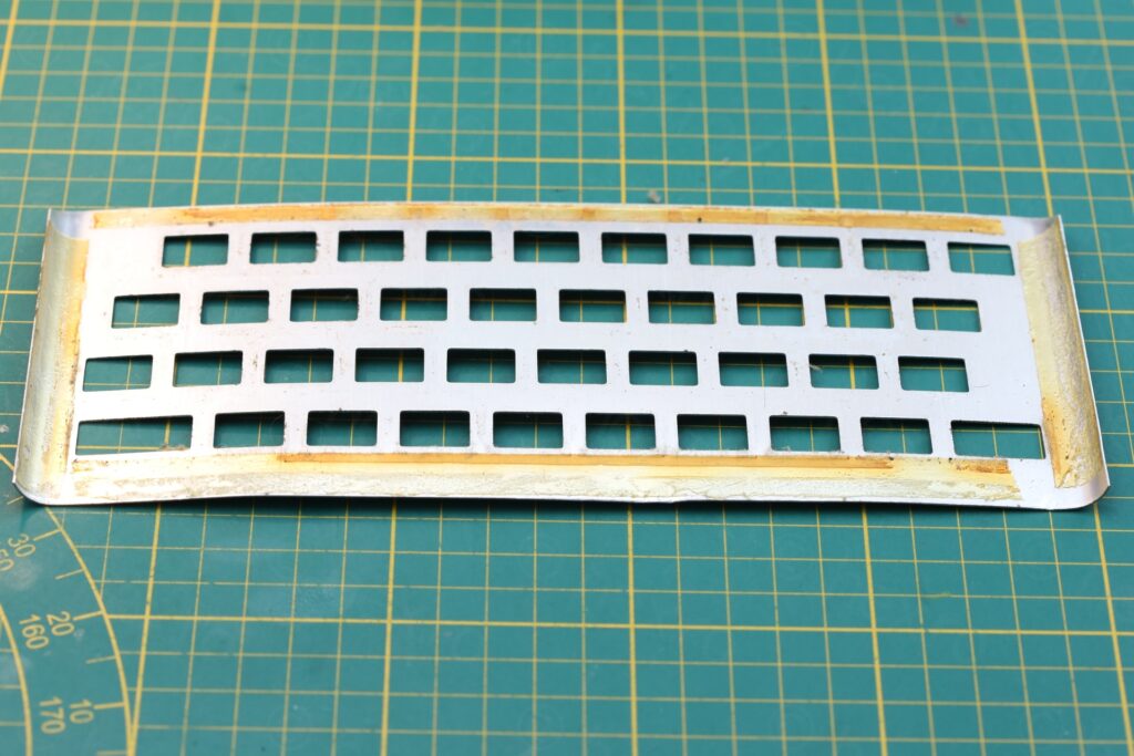
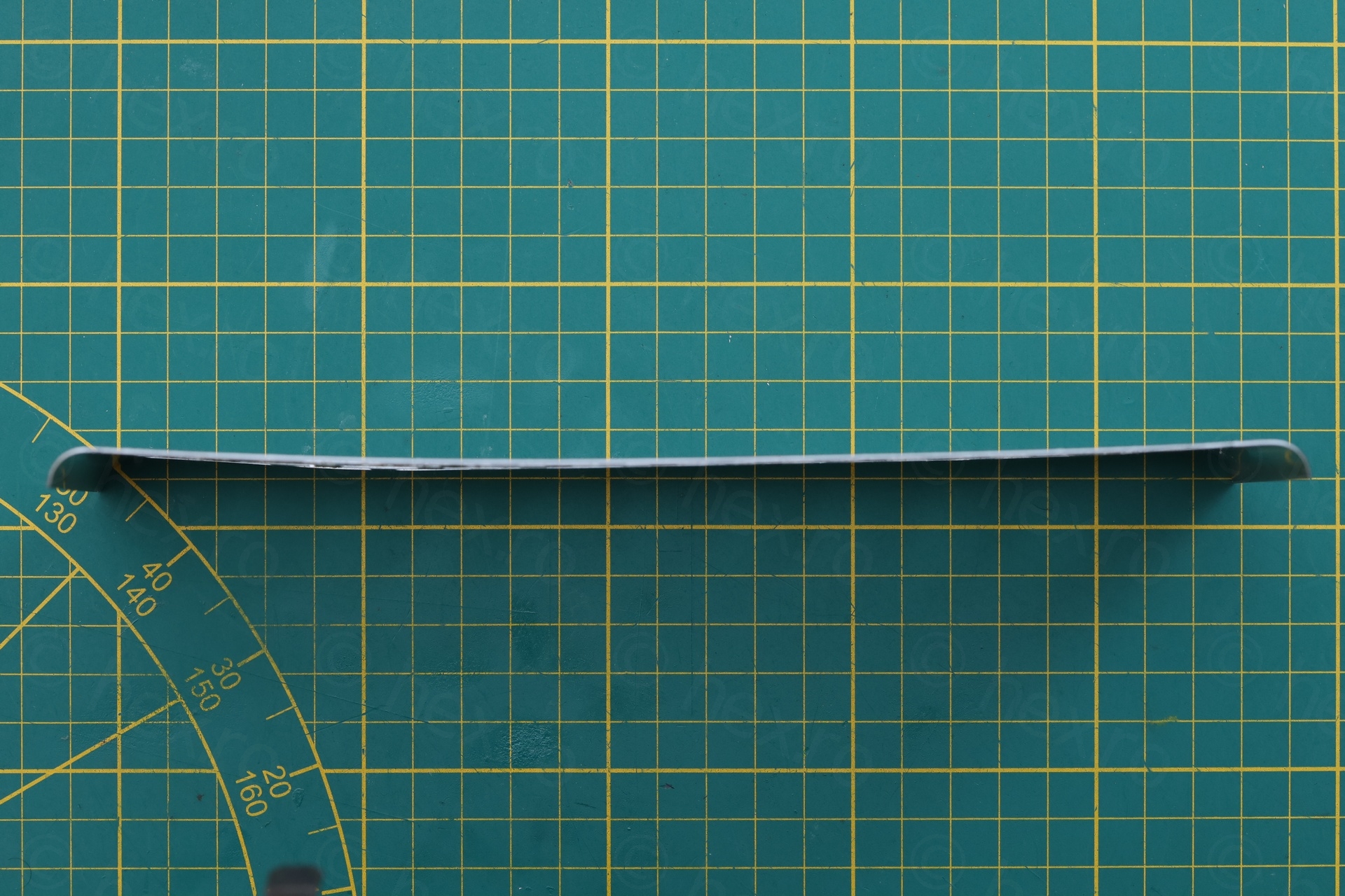
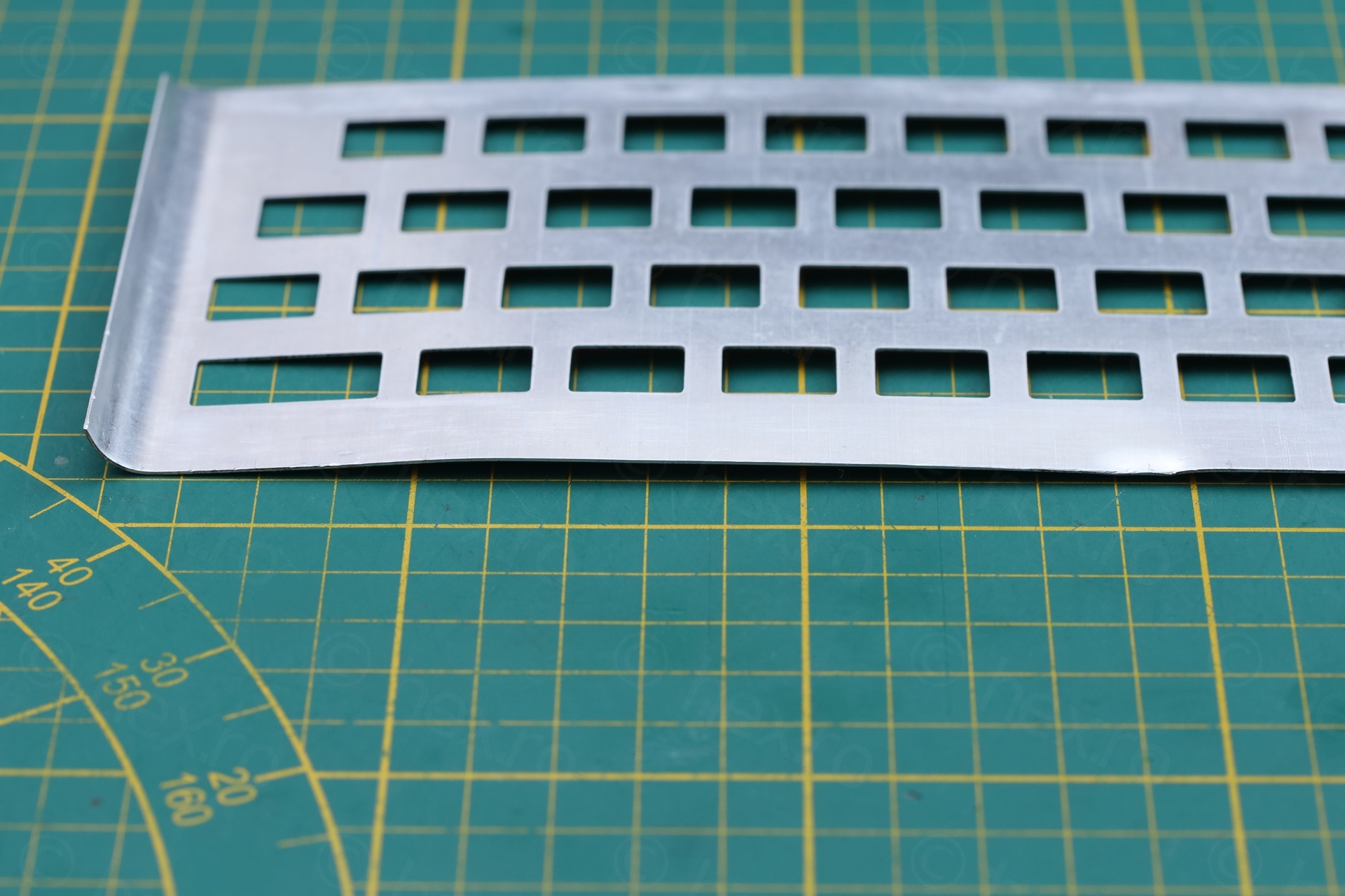
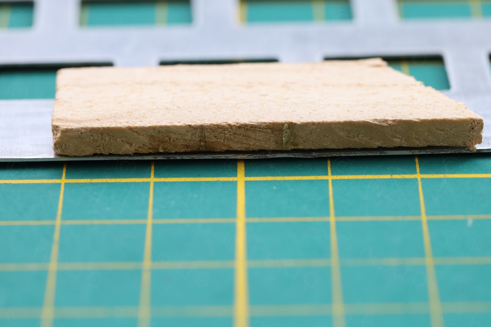
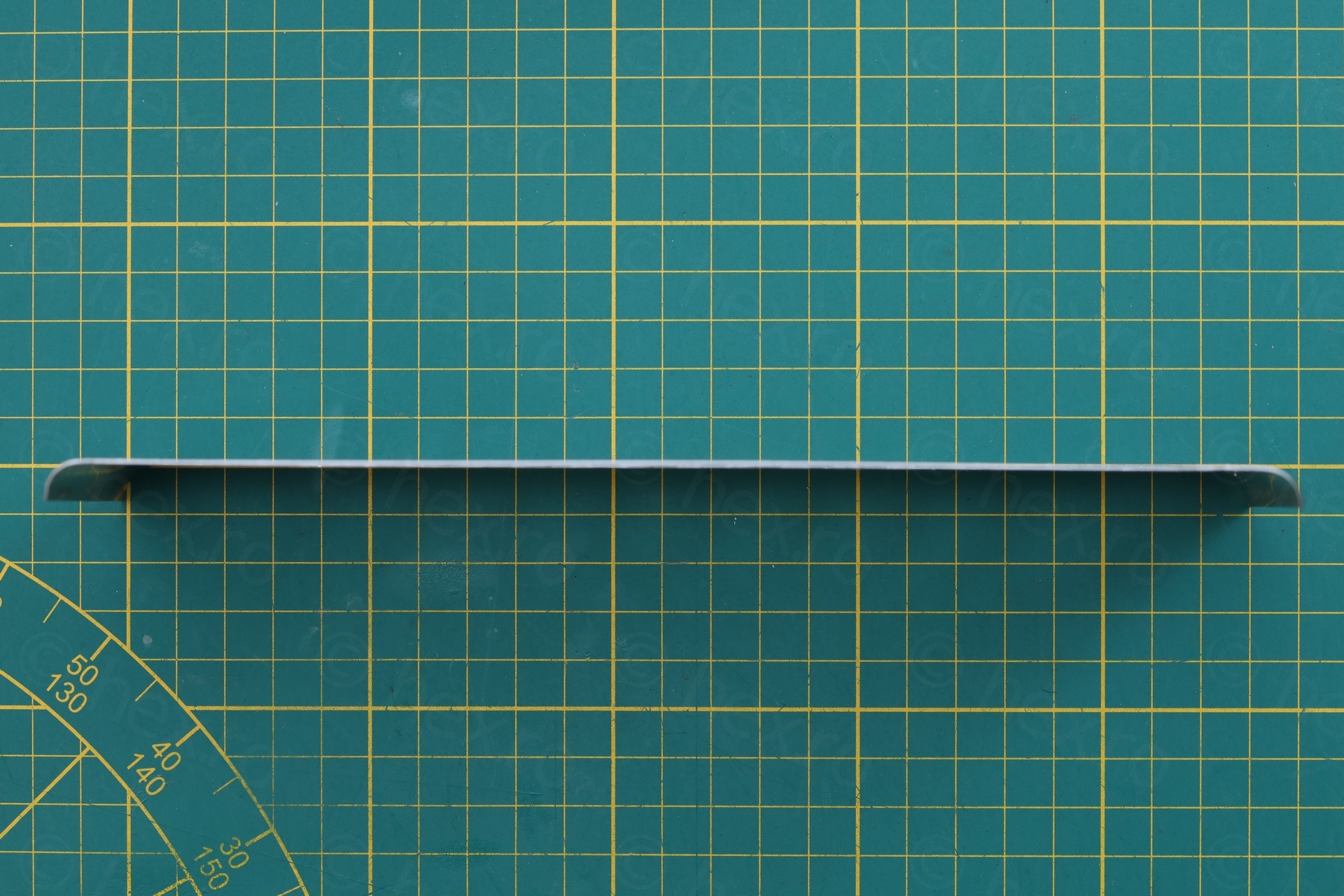
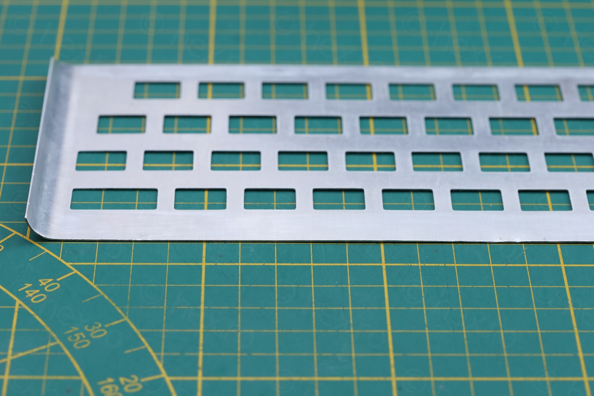
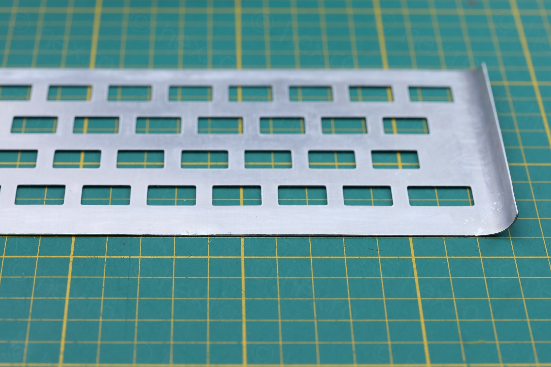
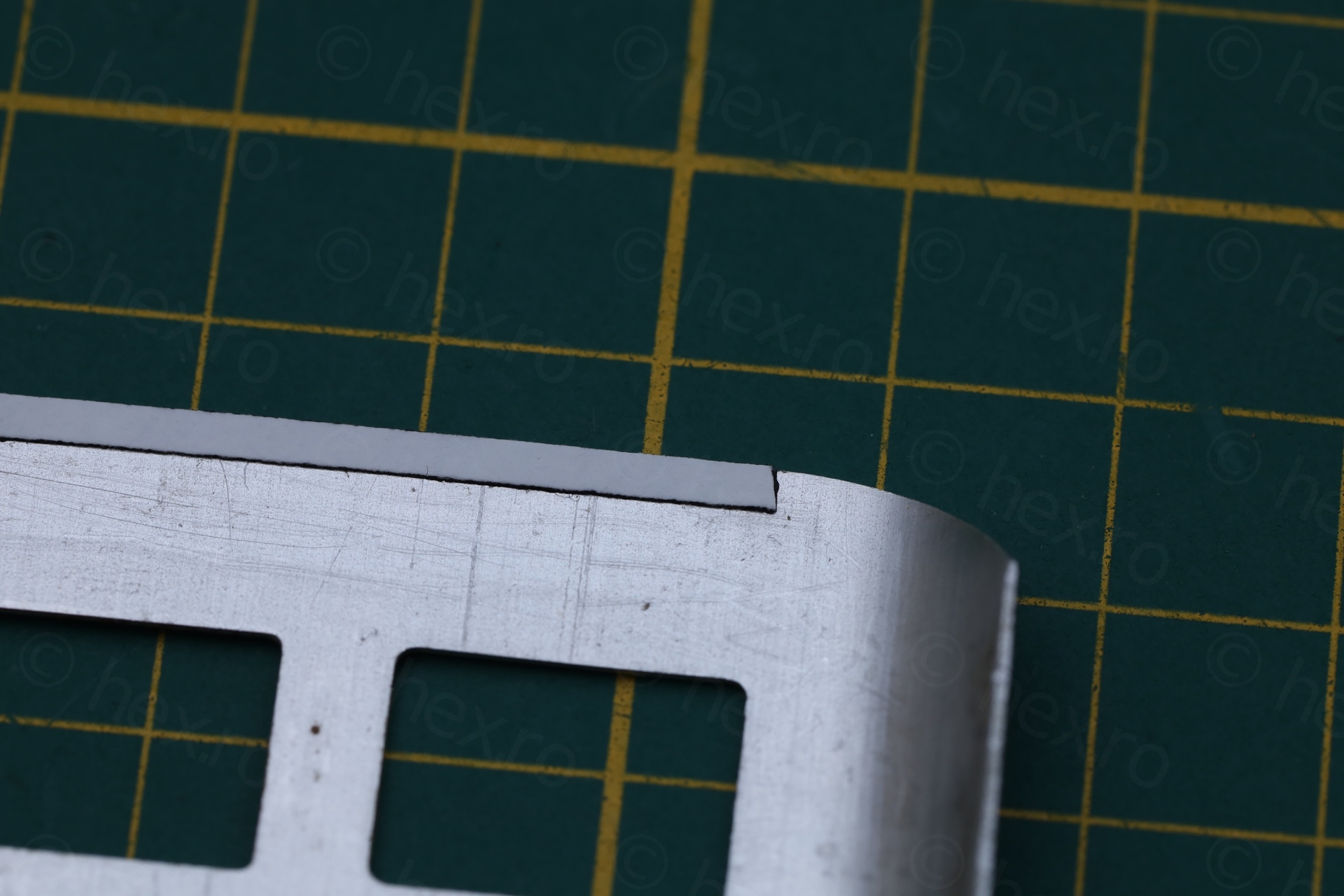
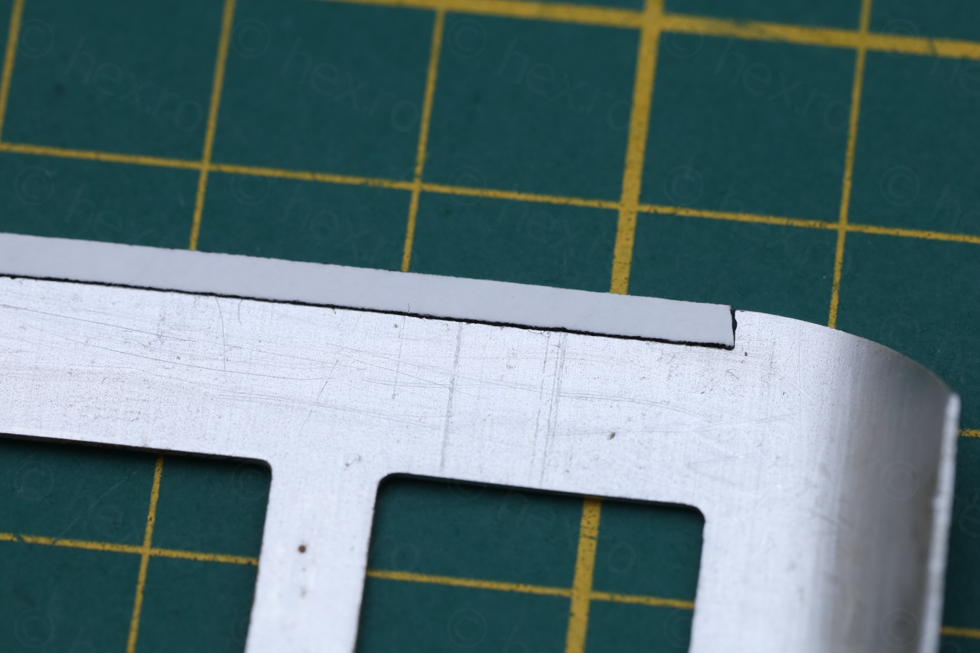
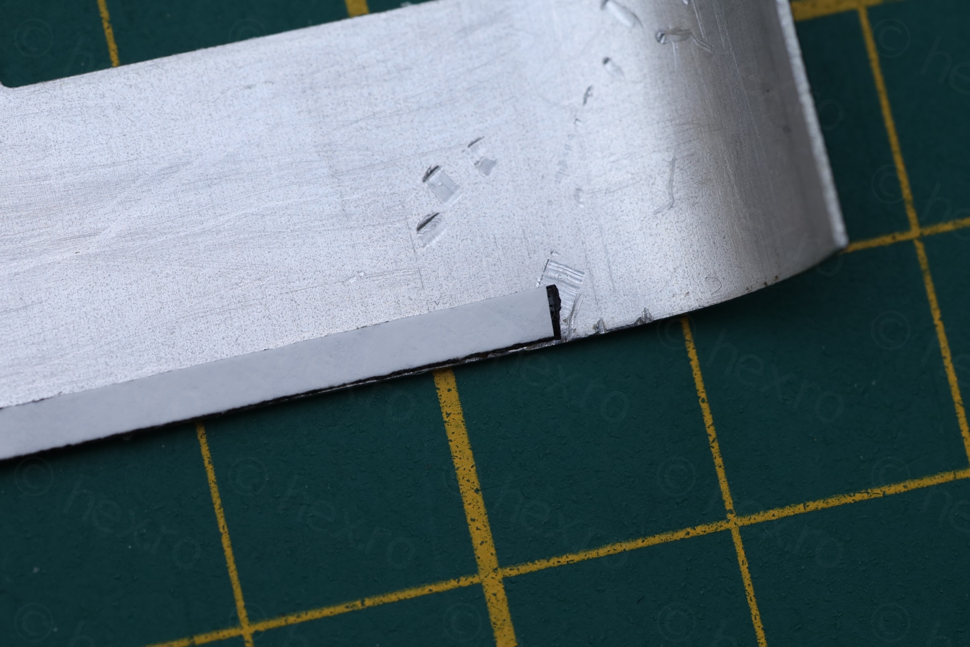
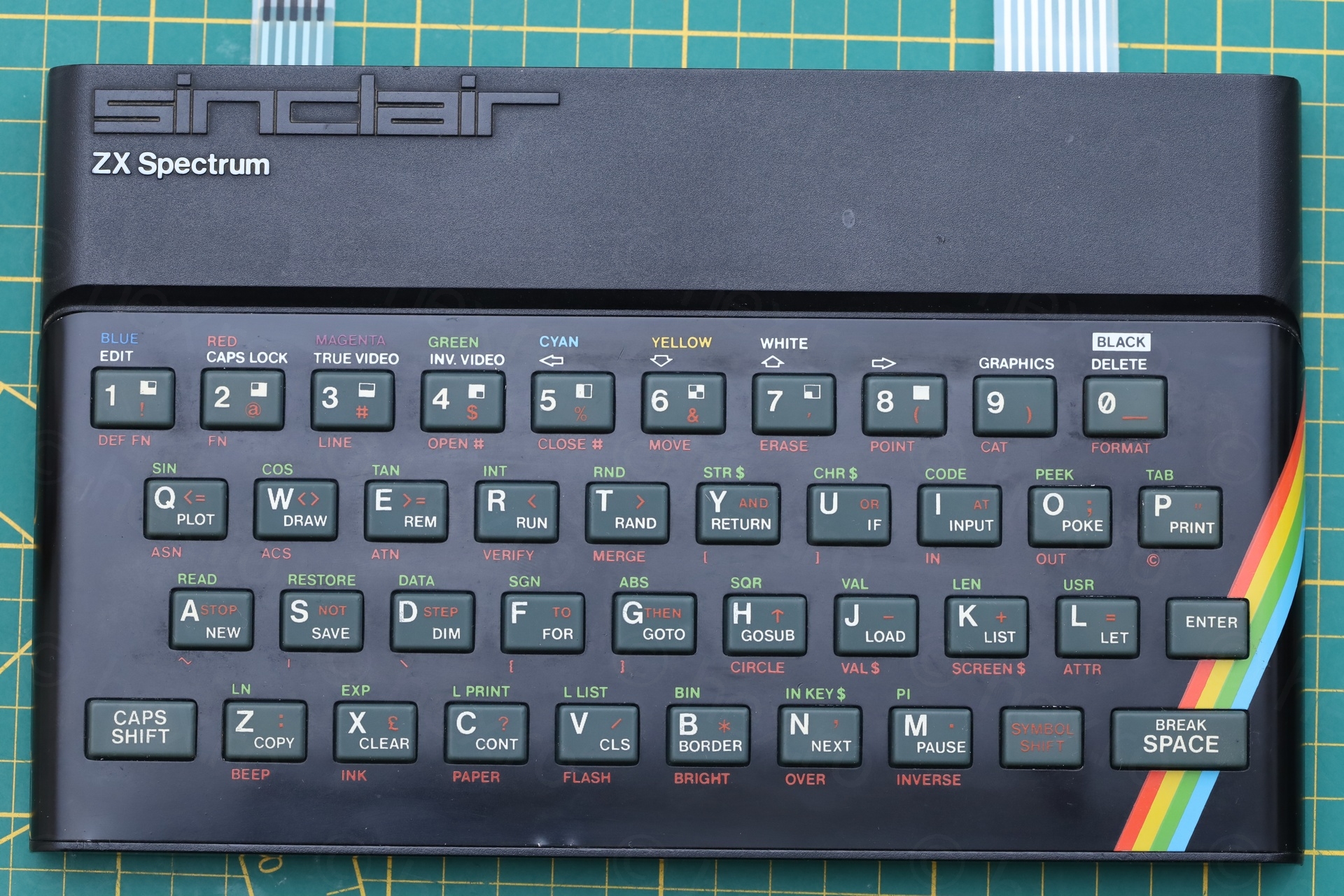
Straightening the face plate
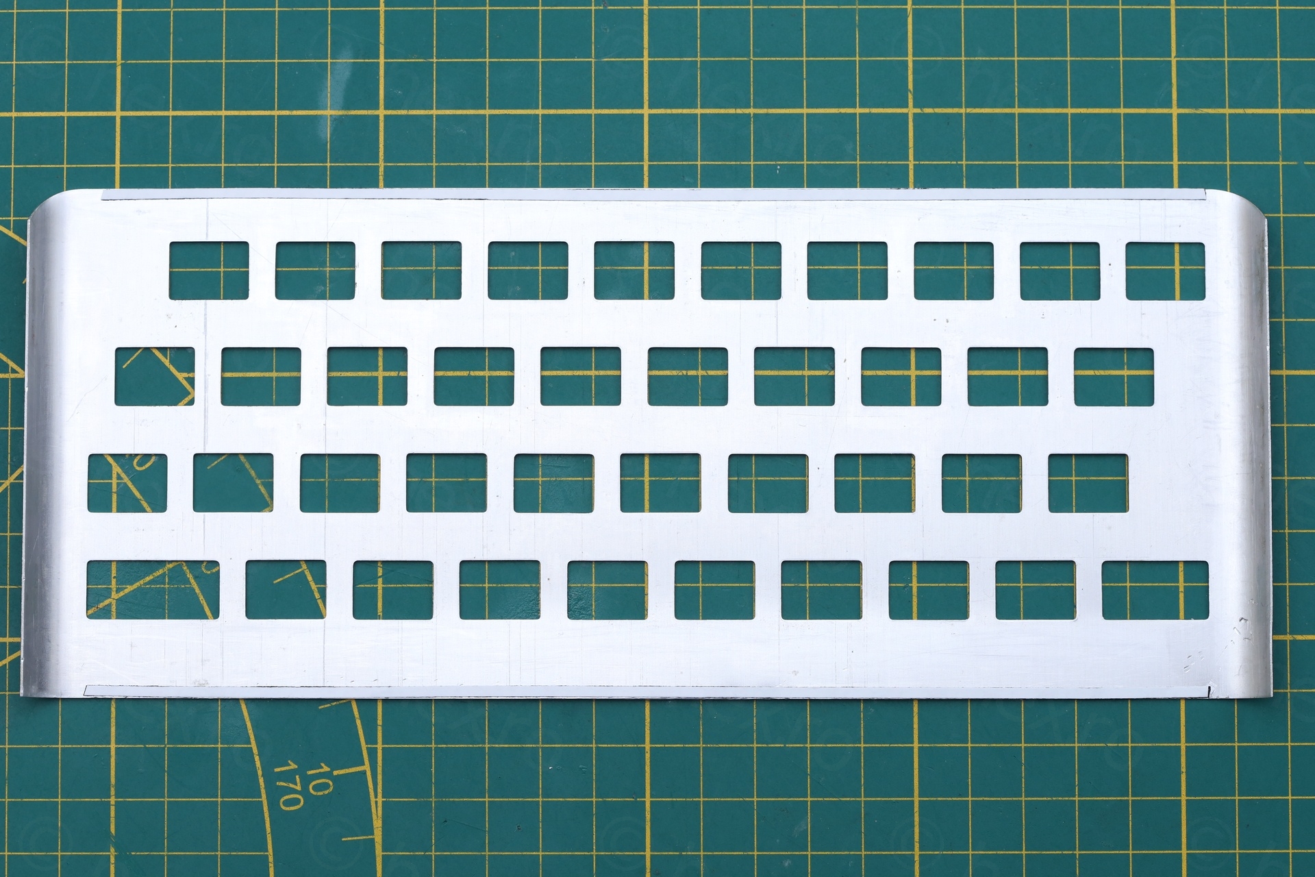
Since the face plate wasn’t too damaged / kinked, I figured, I should try first to straighten it to see if it will look more acceptable. I would like the little computer to retain its troubled past.
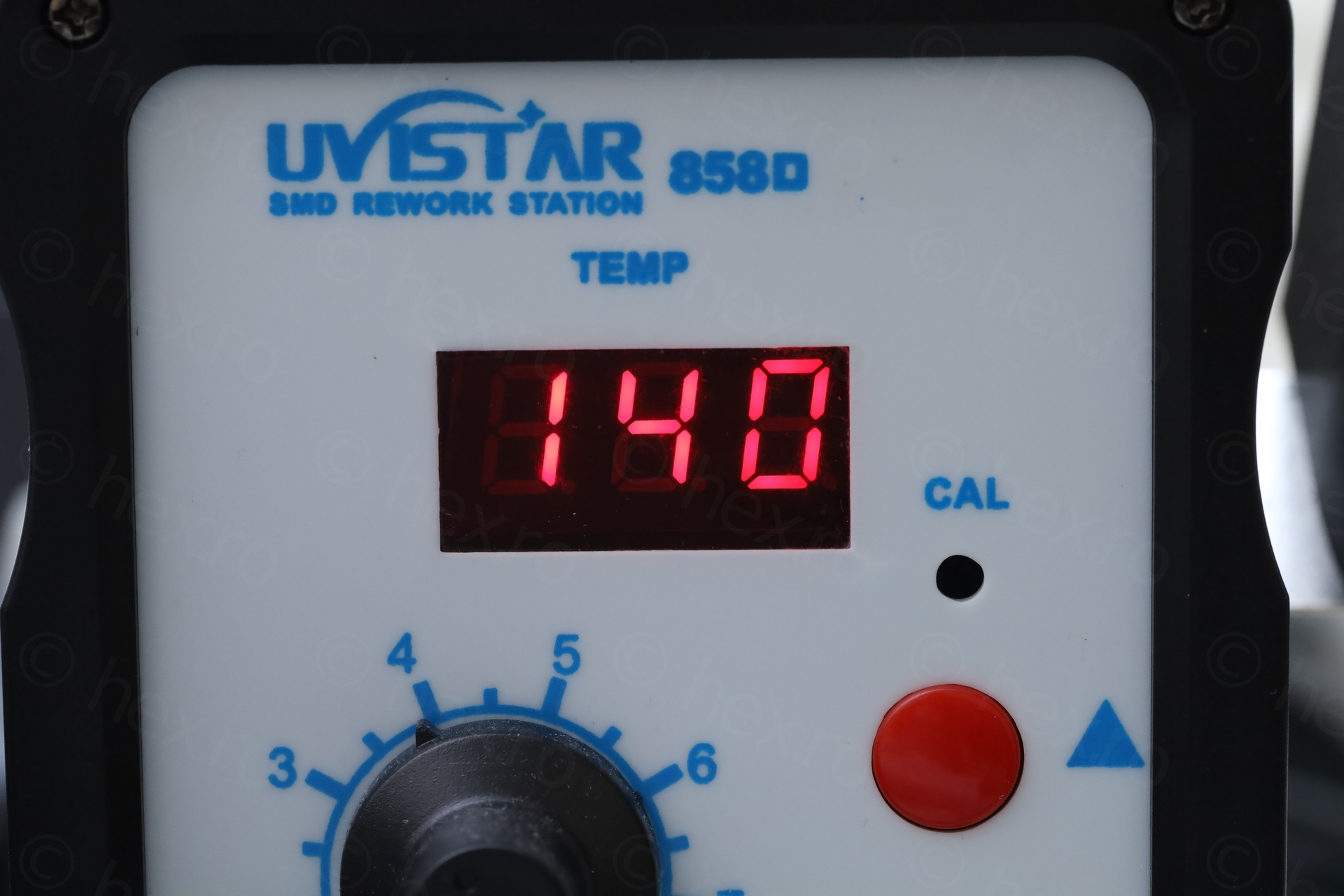
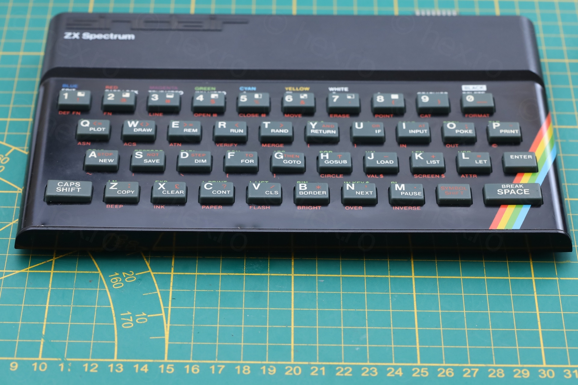
This face plate was the type that was glued to the top case. I used the heat gun with medium nozzle and set to 140C to gently warm up the sides, making sure first not to melt anything, second, not to pull up too hard. It took a while, Aluminum dissipates the heat very quickly. In total maybe 10-15 minutes, but I managed to finish the job started by the seller.
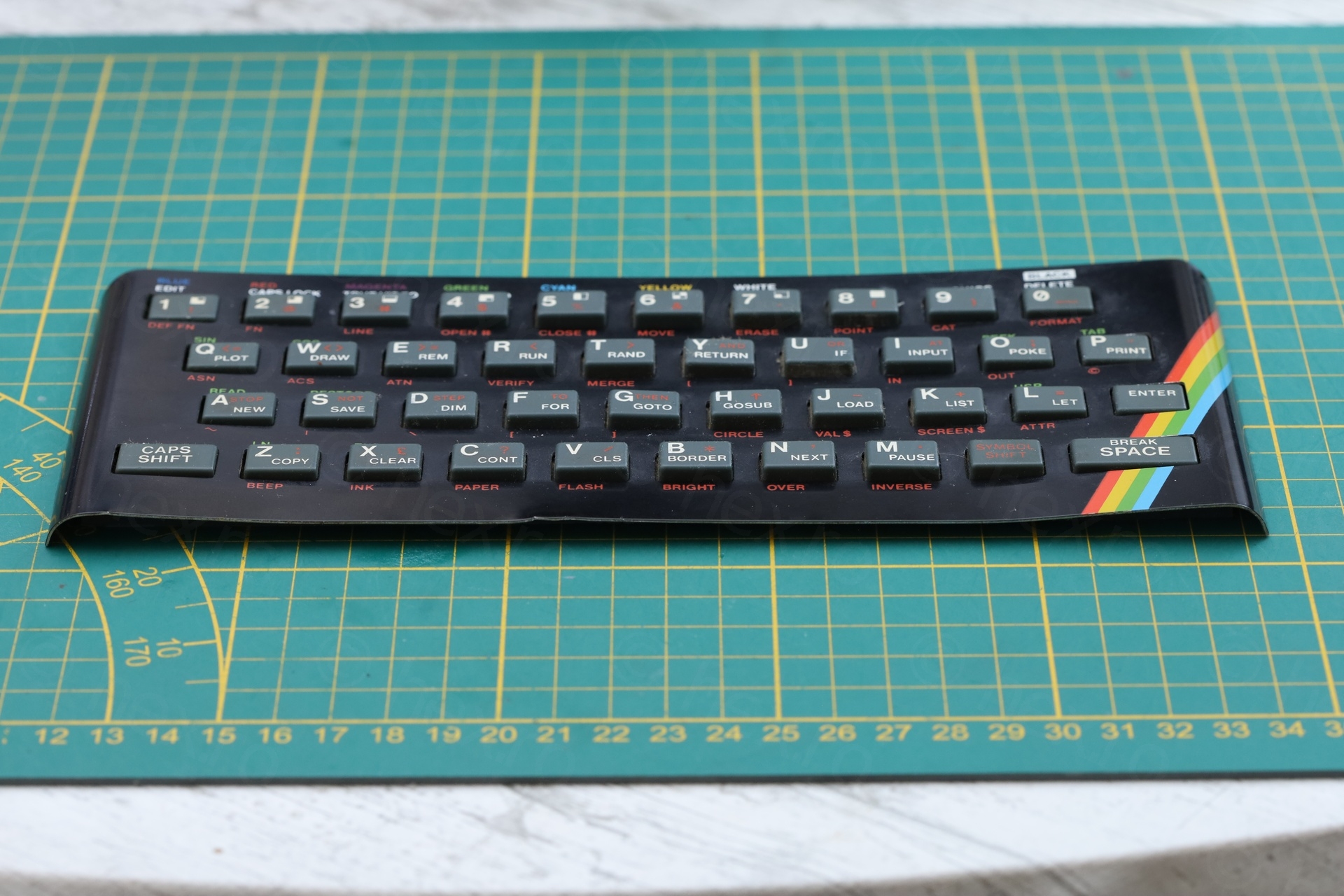
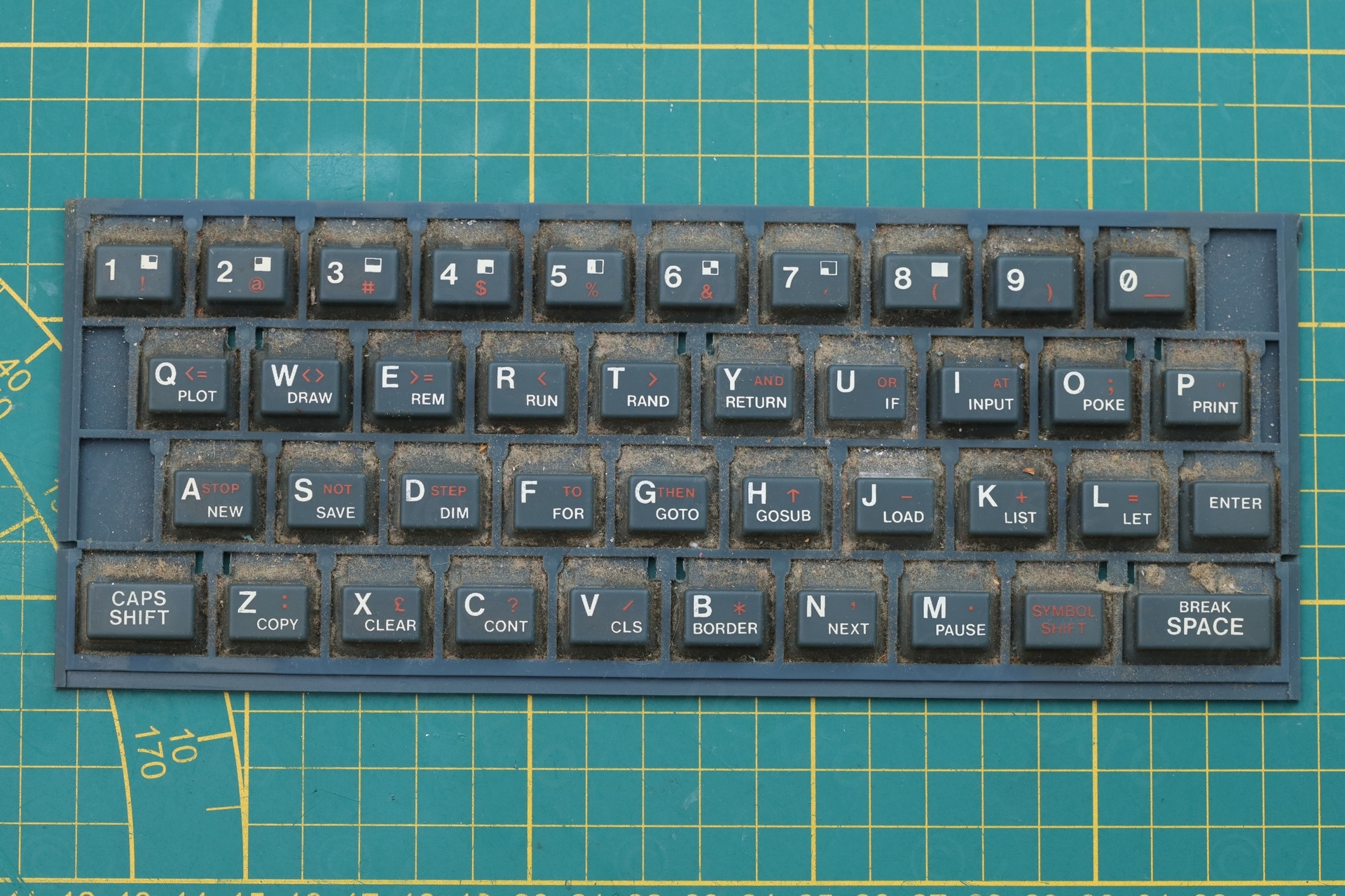
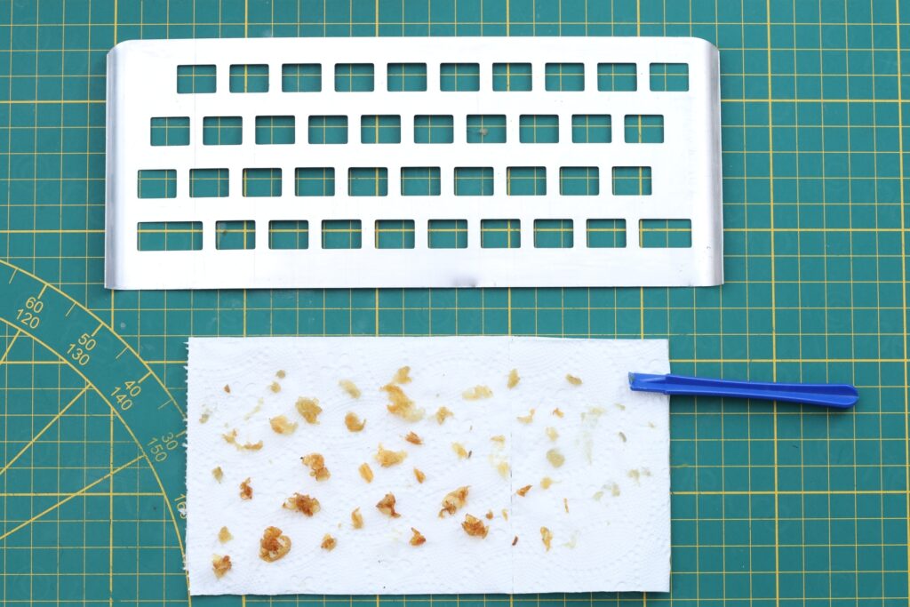
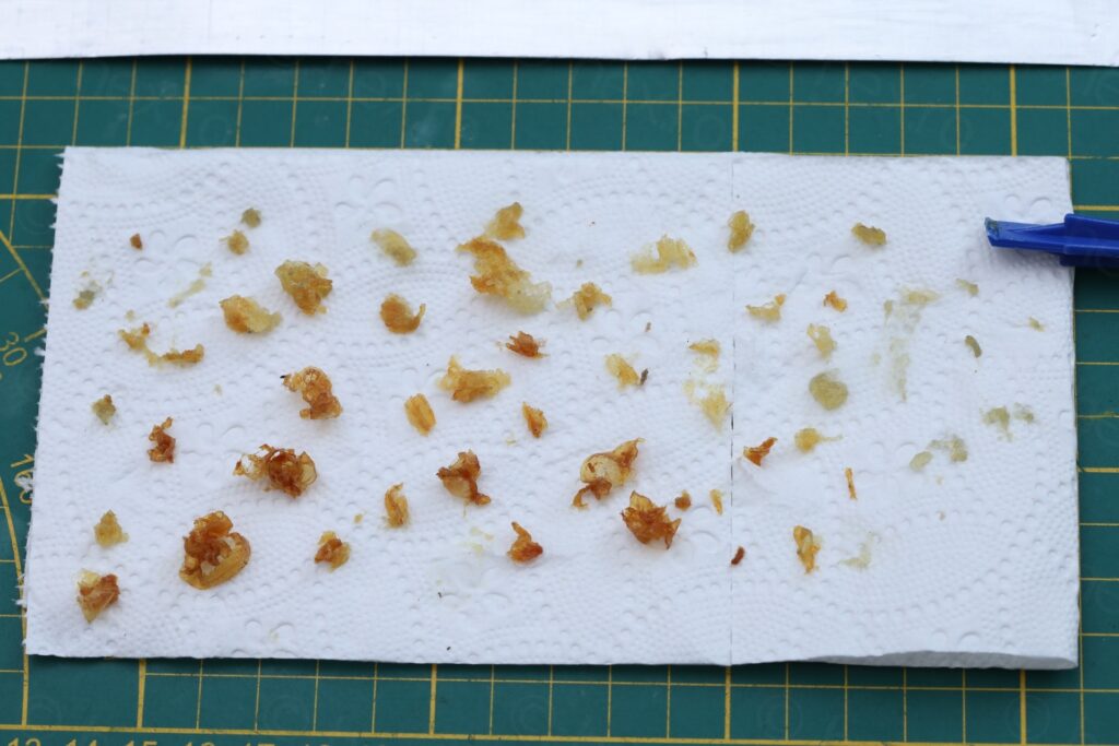
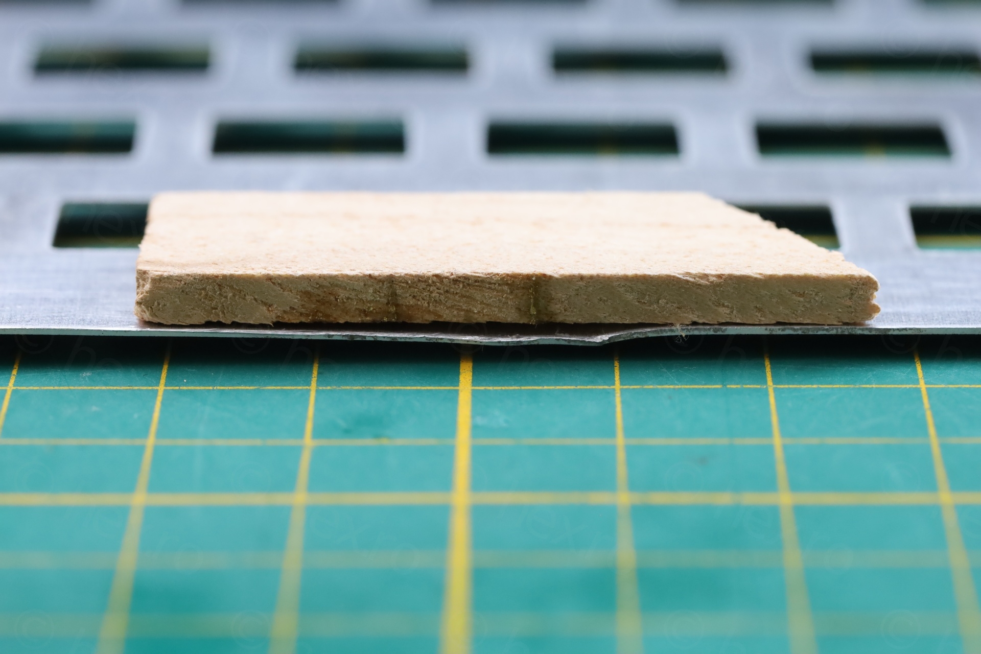
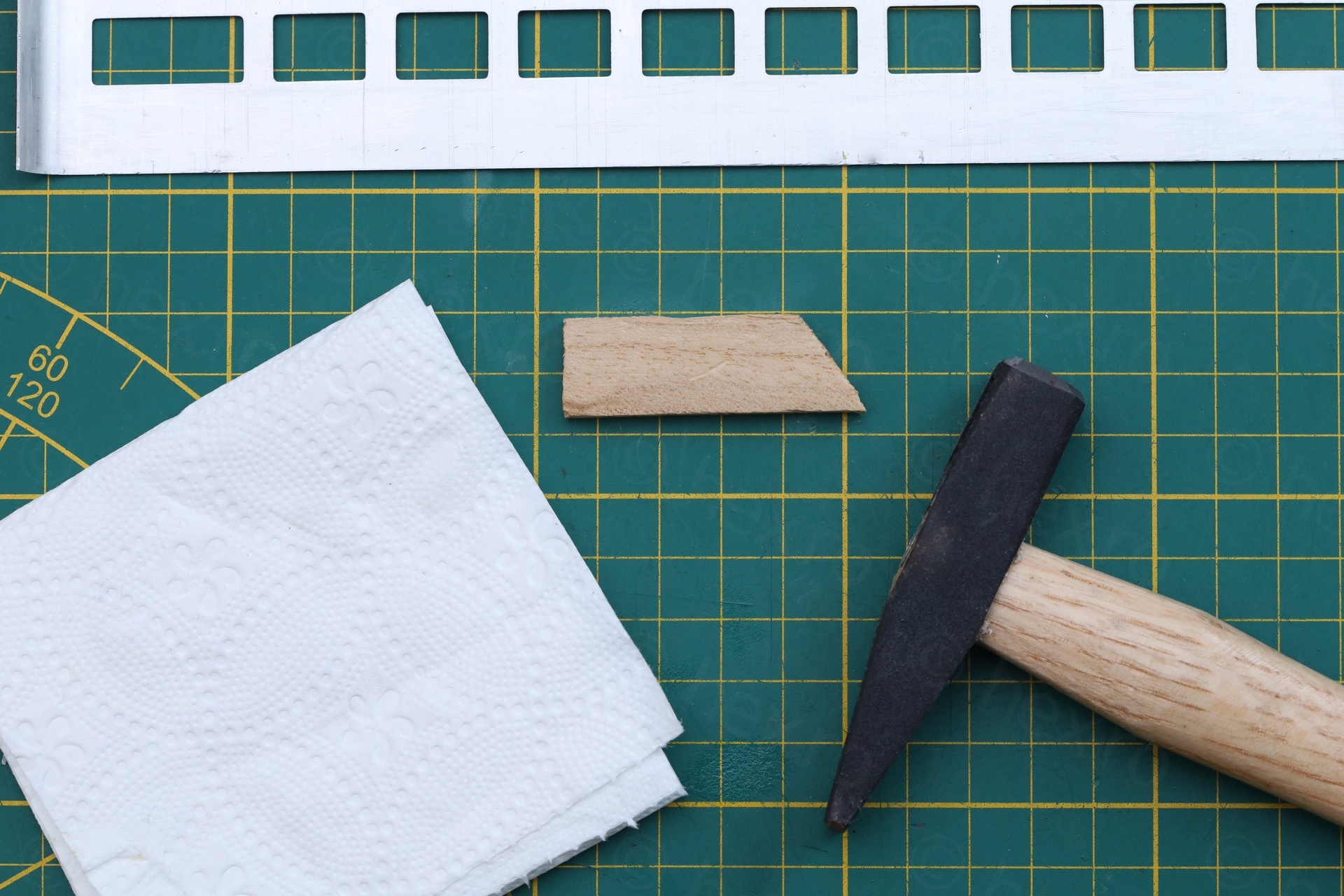
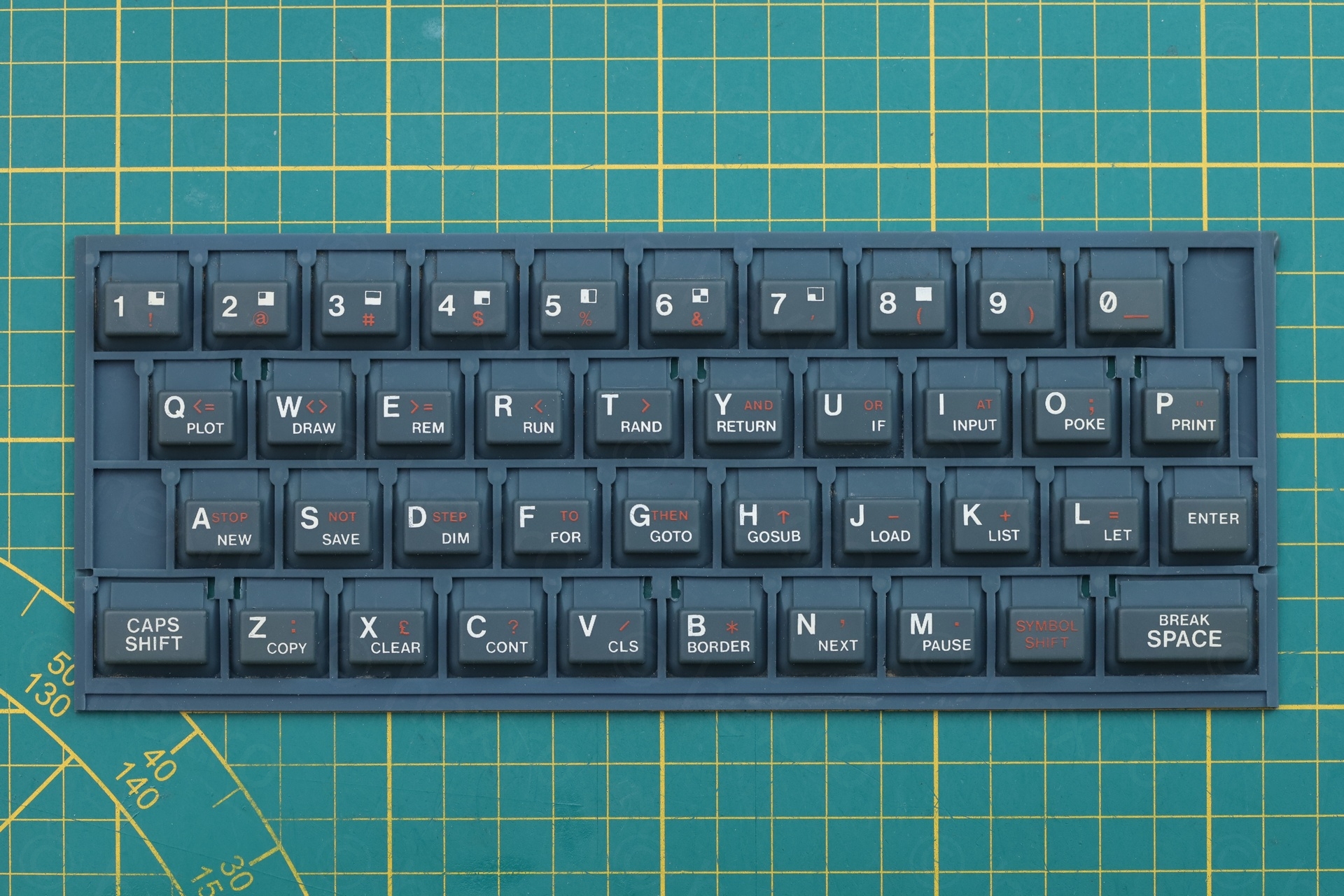
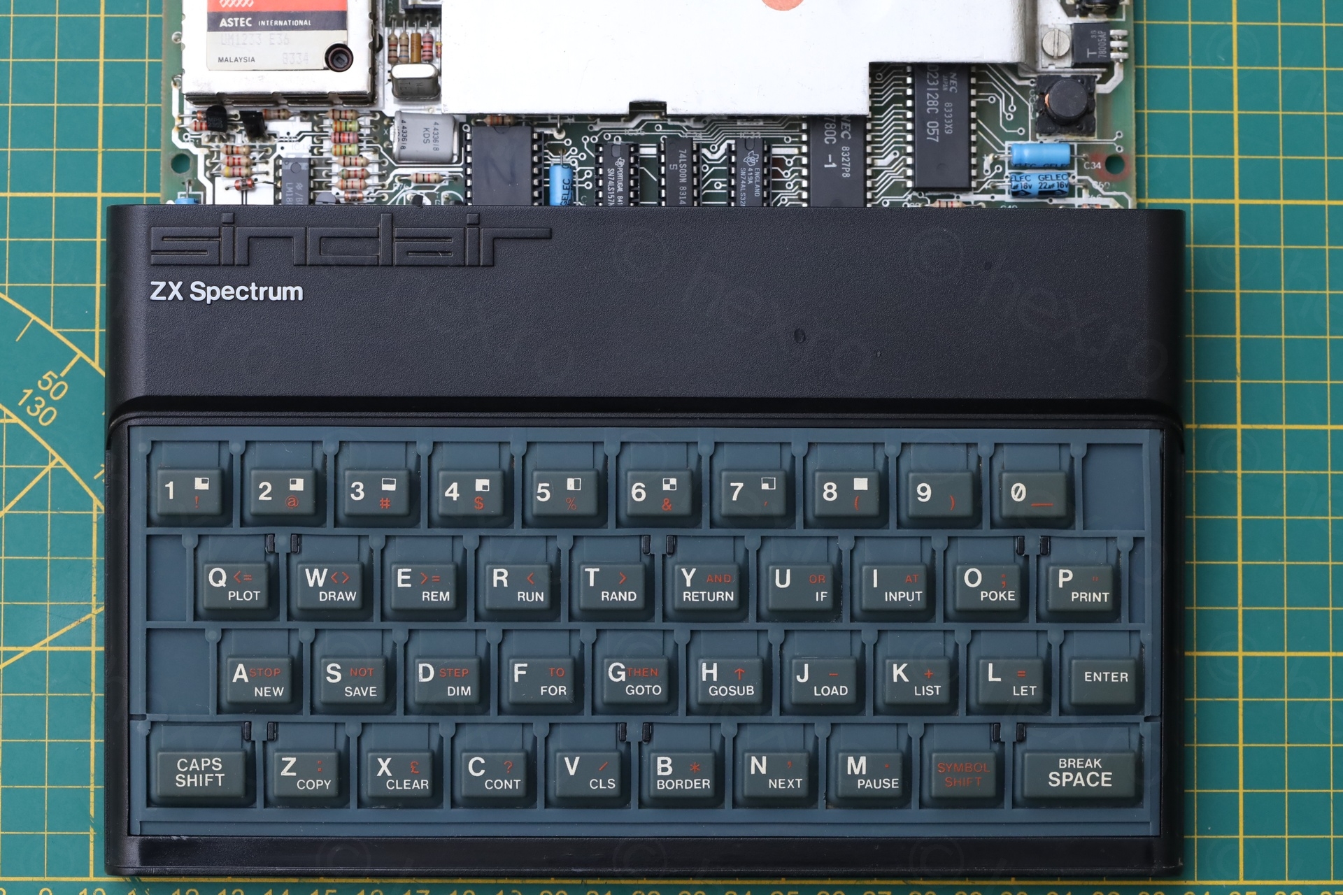
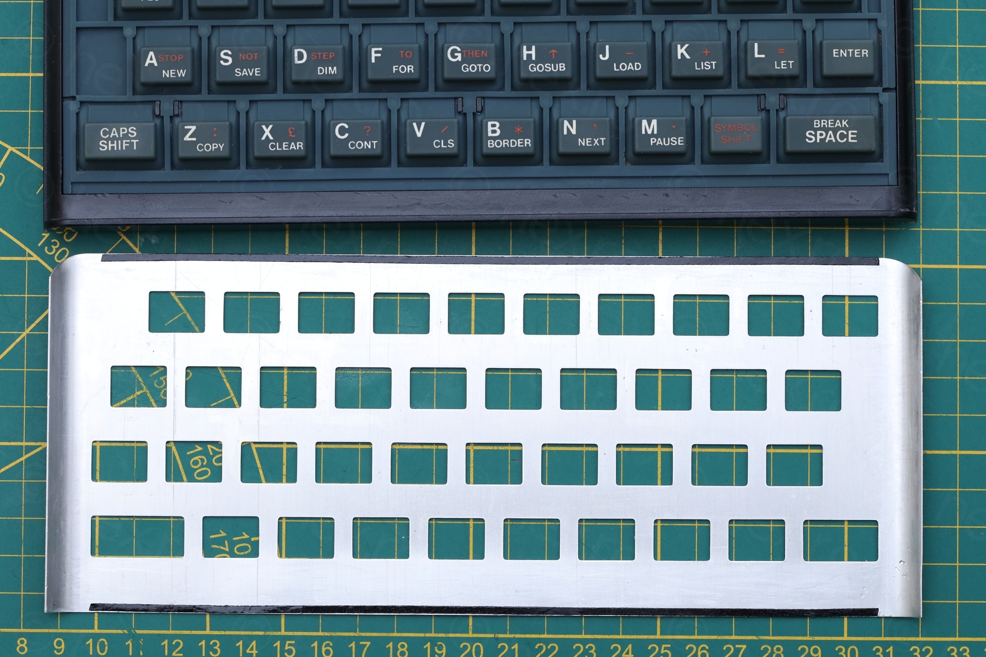
The rubber key mat was filthy. I first hosed it down with water. Then soap + water + hard paint brush to remove all the grime. To remove the old glue, I used alcohol + a little scraper plastic tool. To flatten the kinks, I used a small piece of wood – first pushing down with bare hands, then tapping gently with a small hammer. Also a bit of soft paper under to prevent more scratches to the paint. To bend the face plate back to straight, I gently pushed it against the knee, very very gently, maybe 10 times, always checking for progress. To reattach it, I used a thin double sided sticky tape. Of course, using a fresh keyboard membrane.
Finishing touches
All screws got a small dab of silicone grease.
Summary
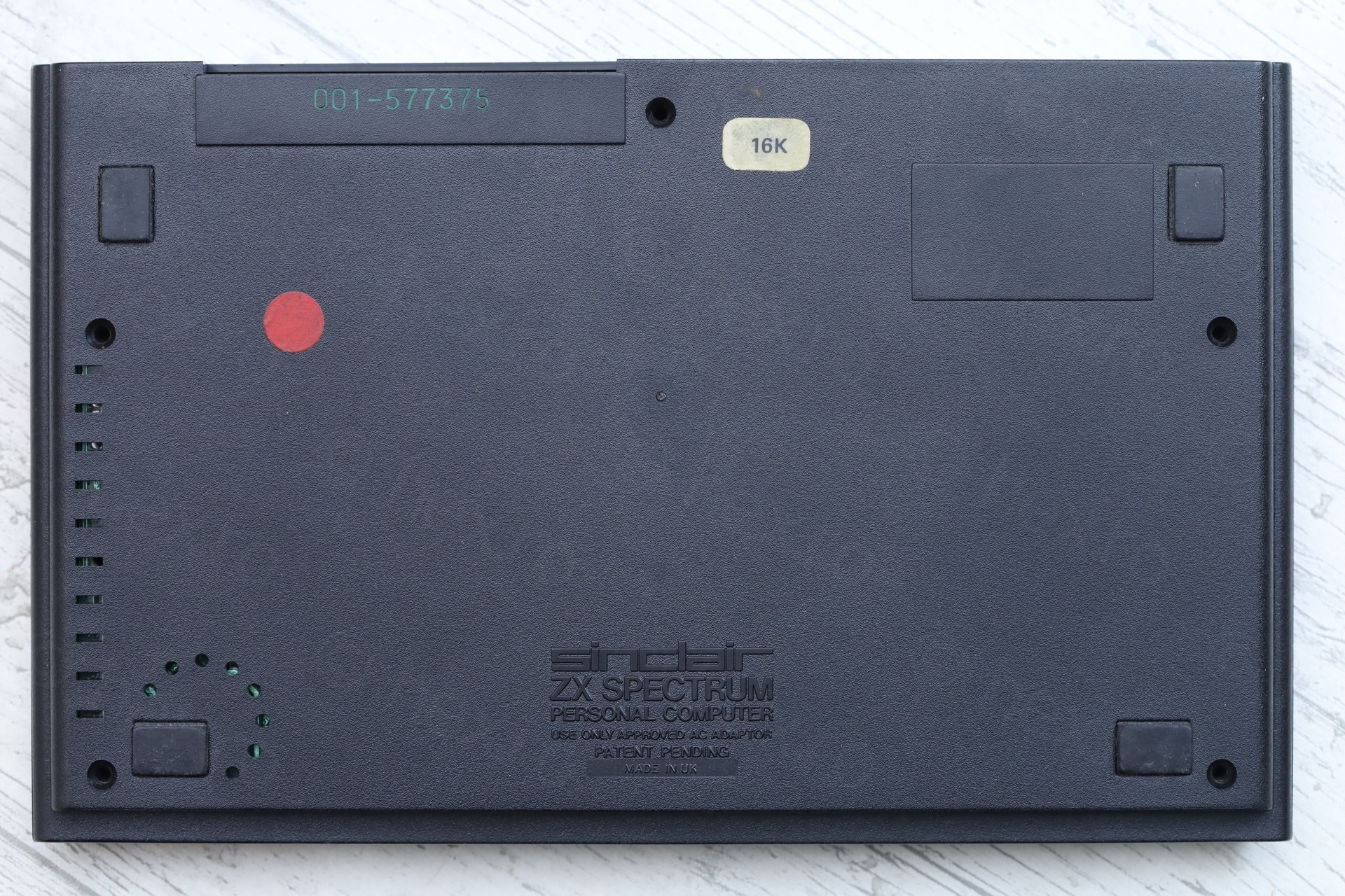
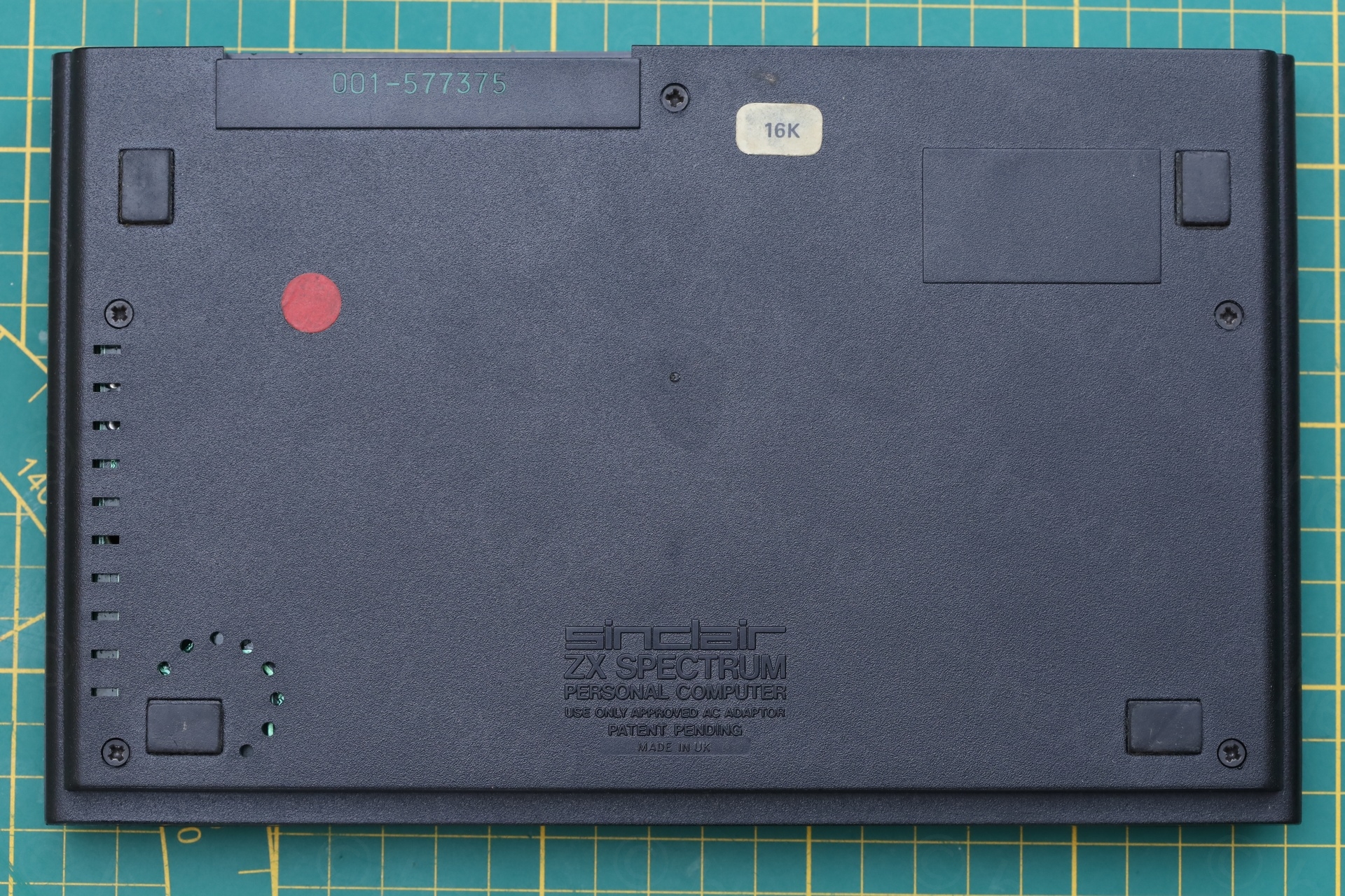
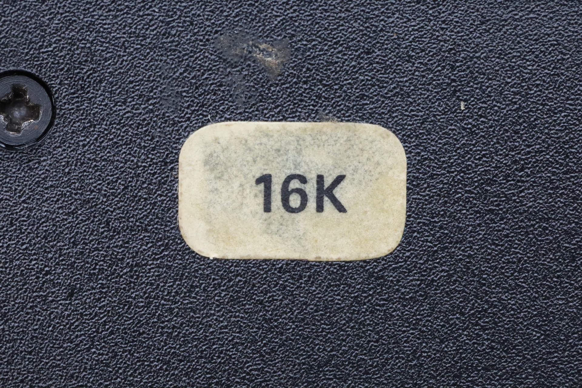
The machine seemed to have been sold with 16Kb RAM only (it has the sticker on the back) and somebody installed 32Kb RAM extension afterwards. This was good since the upper RAM ICs were socketed and thus, easier to swap the two that were broken.
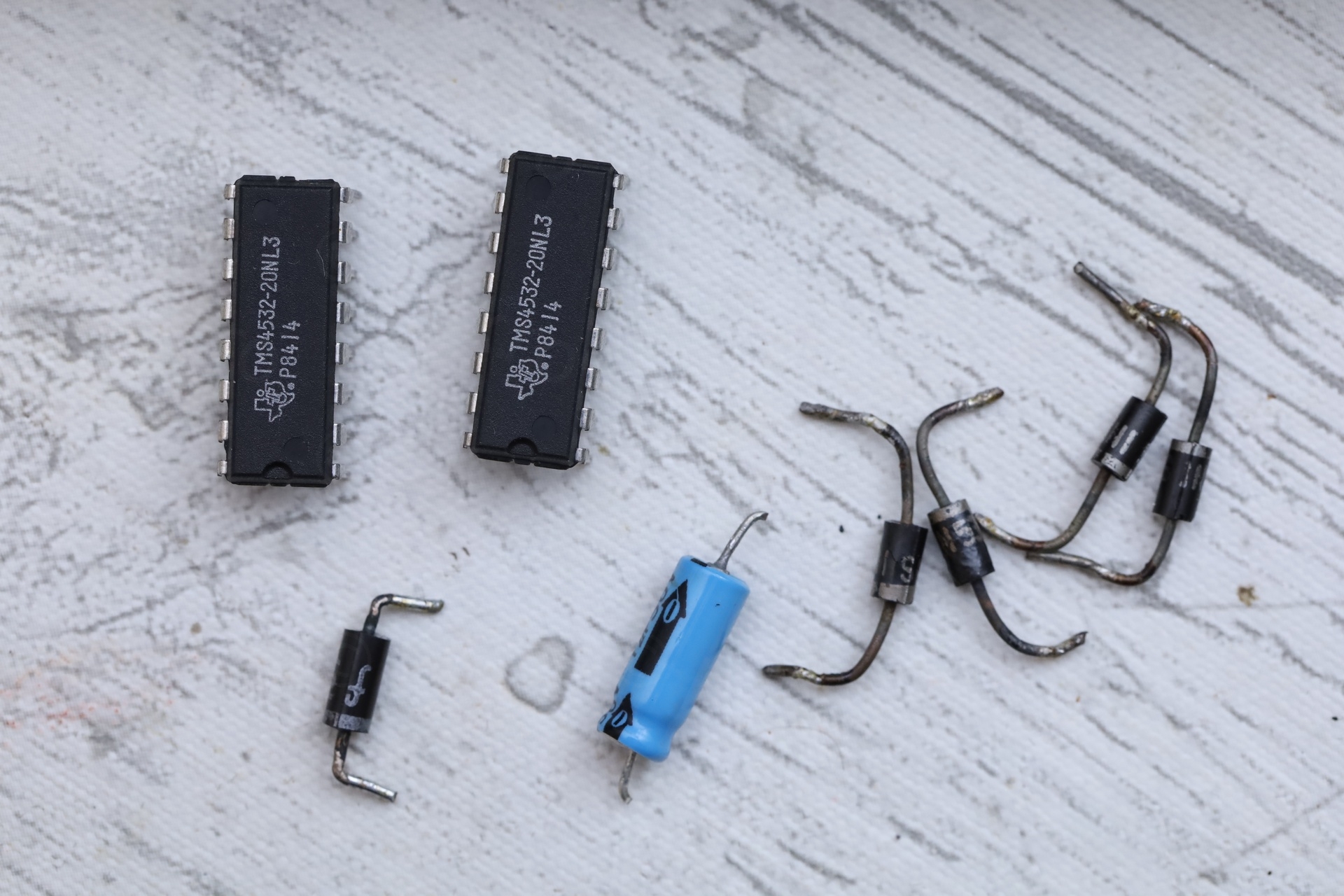
In total, 1 capacitor, 5 diodes and 2 ICs were needed to fix the poor computer:
Christian
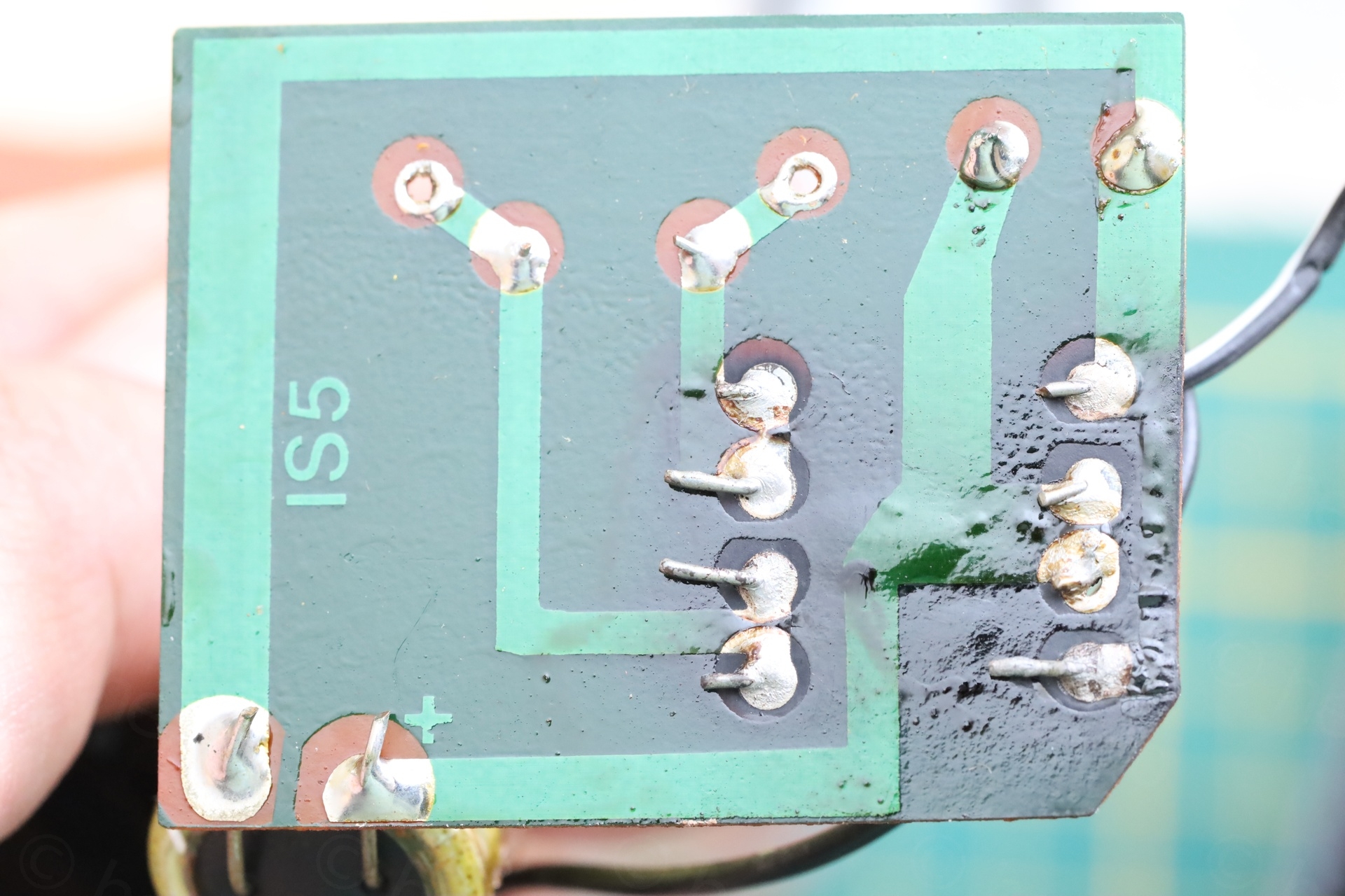
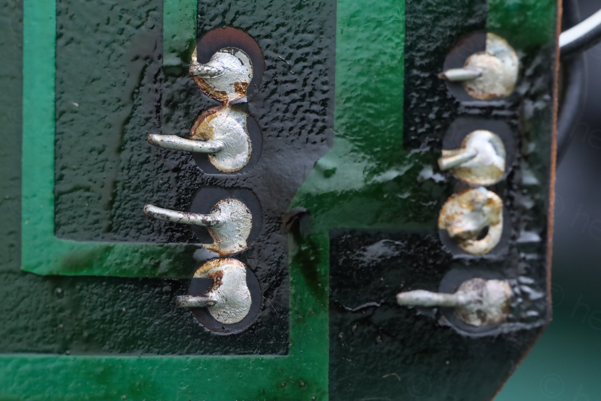
Hi vivulian,
beware of burnt PCB material – it’s literally a carbon resistor now. While at 15V, and with the distances involved, you might get away with it, (barely). In general, if the PCB is charred like this, it has to be cut away to make the circuit reliable again. For restoring, pieces of protoboard and/or copper wire and epoxy have been working for me.
Safe repairs,
Christian
viulian
Wow, thank you very much for the heads-up!
I never considered the leakage resistance of a burned circuit board and you are totally right, I should have checked it. I am not using these old power supplies anyway, I prefer to use a DC/DC converter with current limiting and with display of the instant current draw. Me I was happy that at least the traces where still attached to the board. Since this specific board is easy, it may be a good incentive for me to start learning Kicad board design and try to clone it 🙂 Otherwise, your ideas are very good.