


Introduction
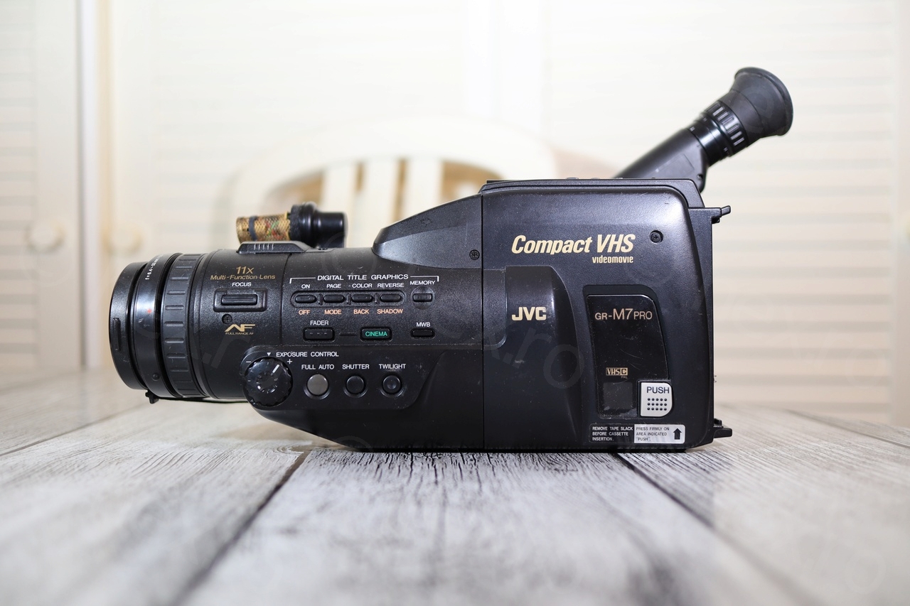
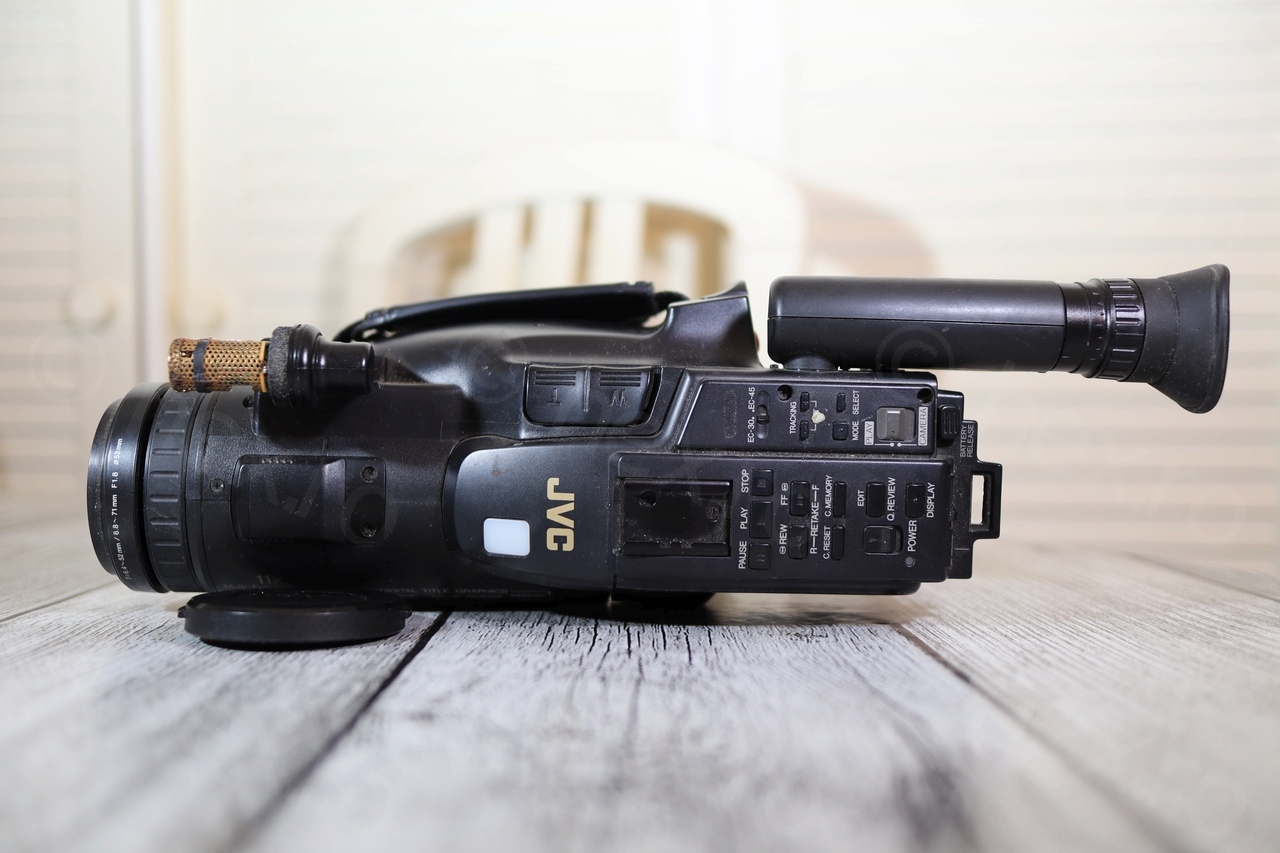
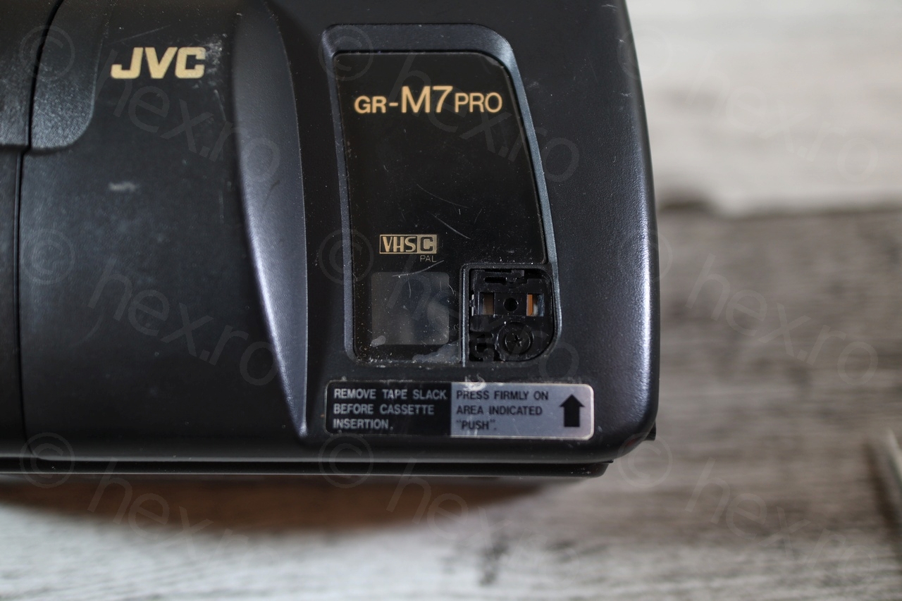
This mini CRT came from a JVC GR-M7PRO / JVC GR-M7EG video camera that I bought at a flea market. It was the most difficult one to get going (from the other 3 that I looked so far). Trouble was that some electrolytic capacitors have leaked on the board, but on this, a little bit later.
Camera tear-down
The JVC GR-M7PRO camera was a little tricky to take apart due to some hidden screws. Not that I keep the shell, but sometimes is tiring to walk the line between enjoying the small challenges to locate the screws and the frustration when that takes too much time.
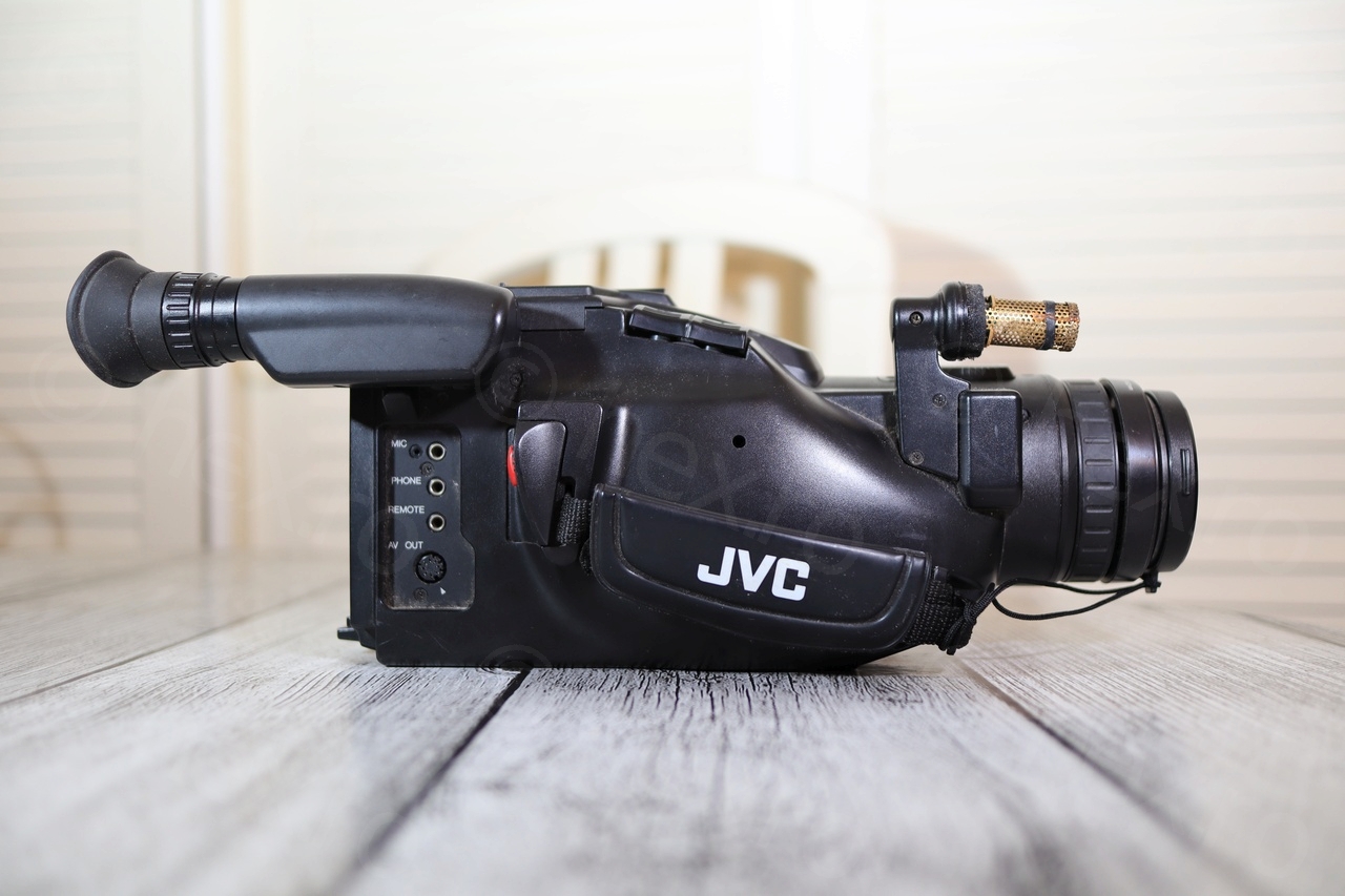

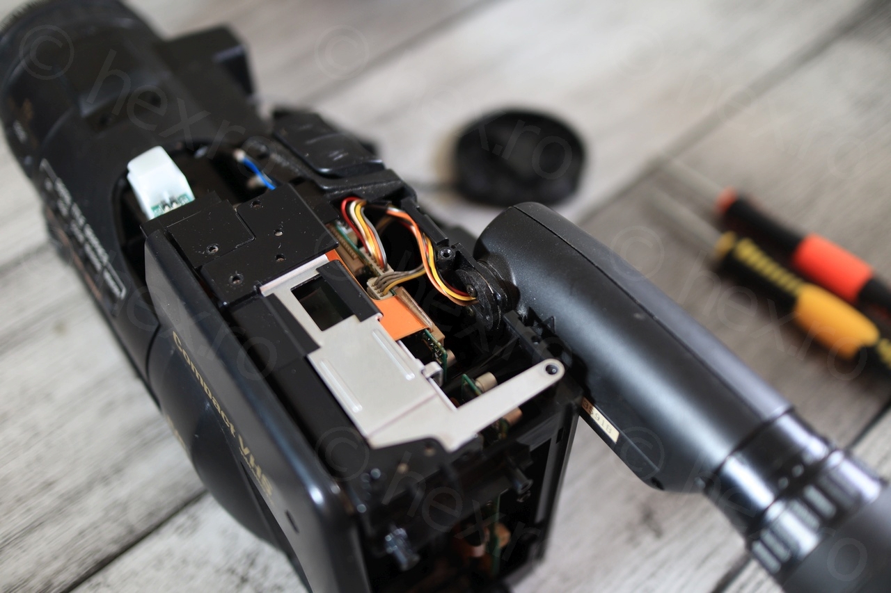
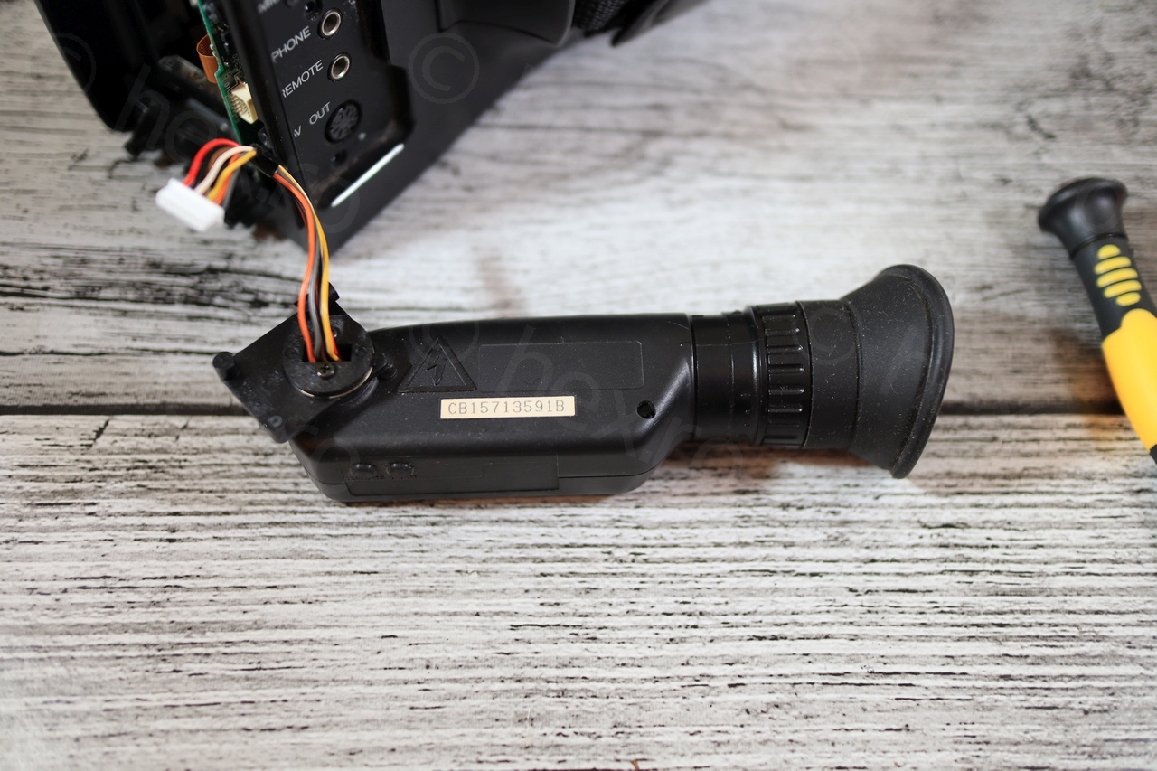
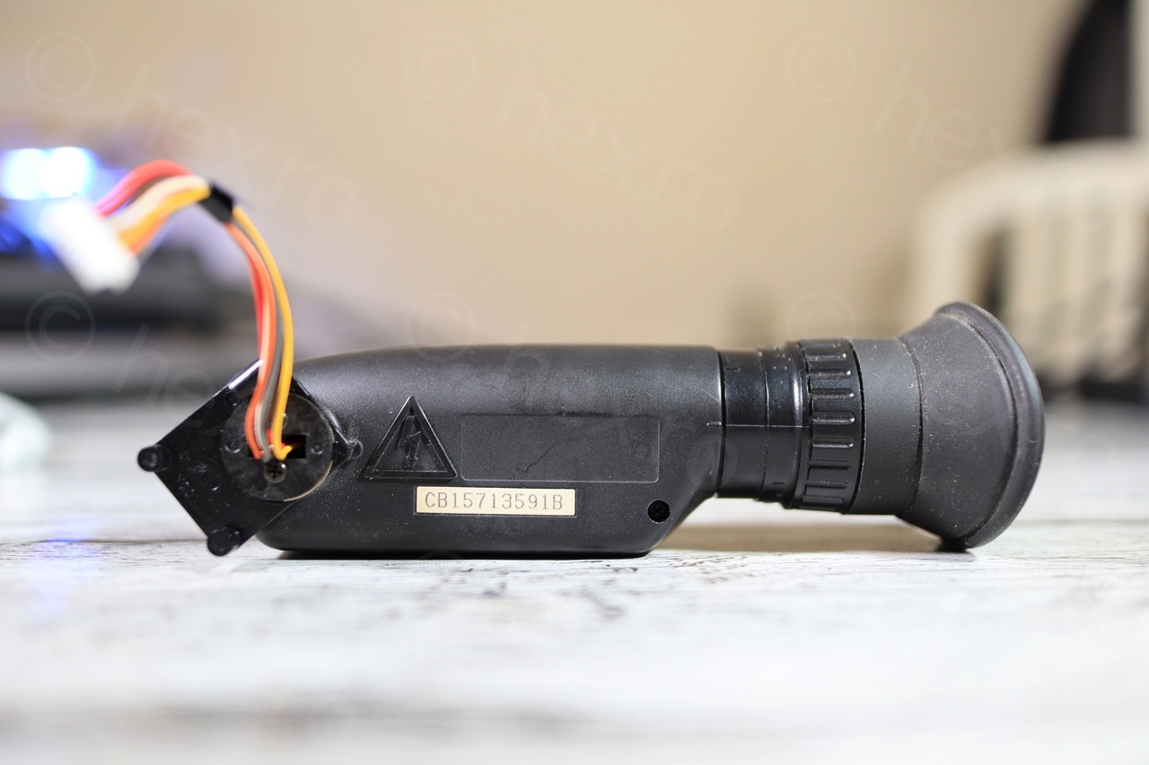
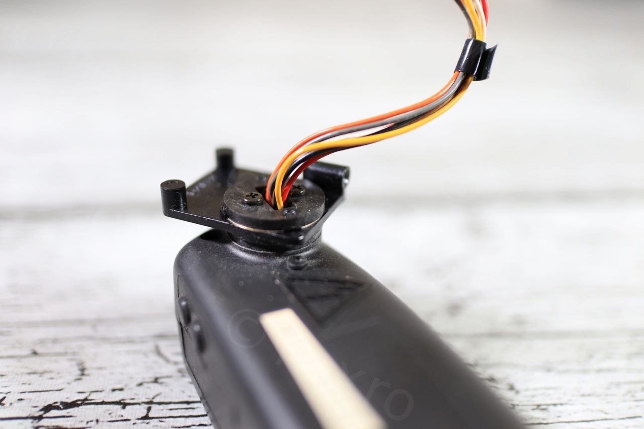
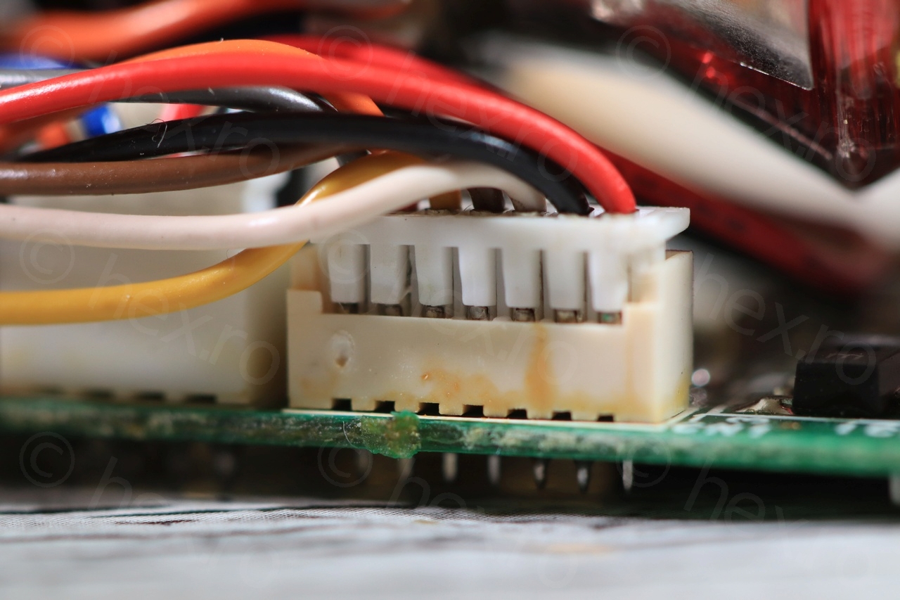
Once starting to take the visible screws out, it became obvious that the electronic view finder is easy to take out. The connector is color coded, was hoping for an easy way to identify the Video IN and Vcc/GND signals.


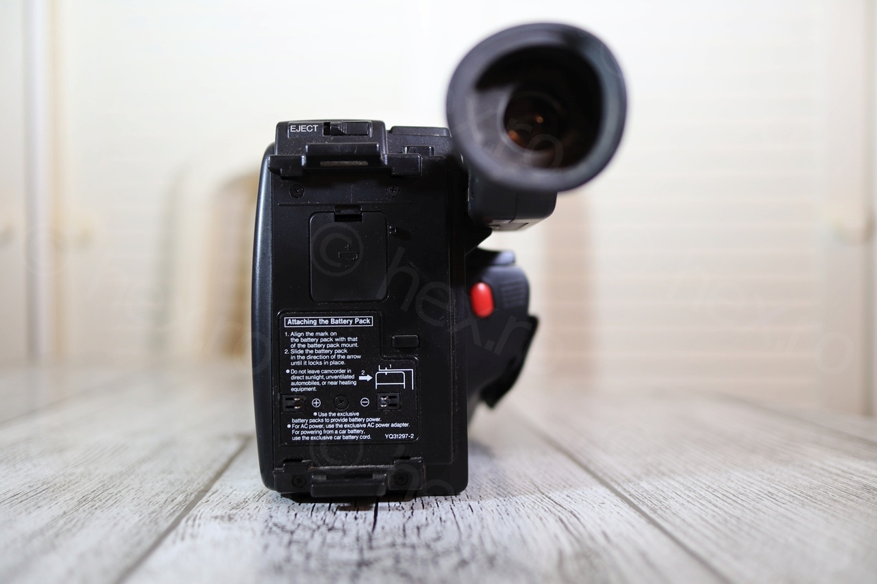
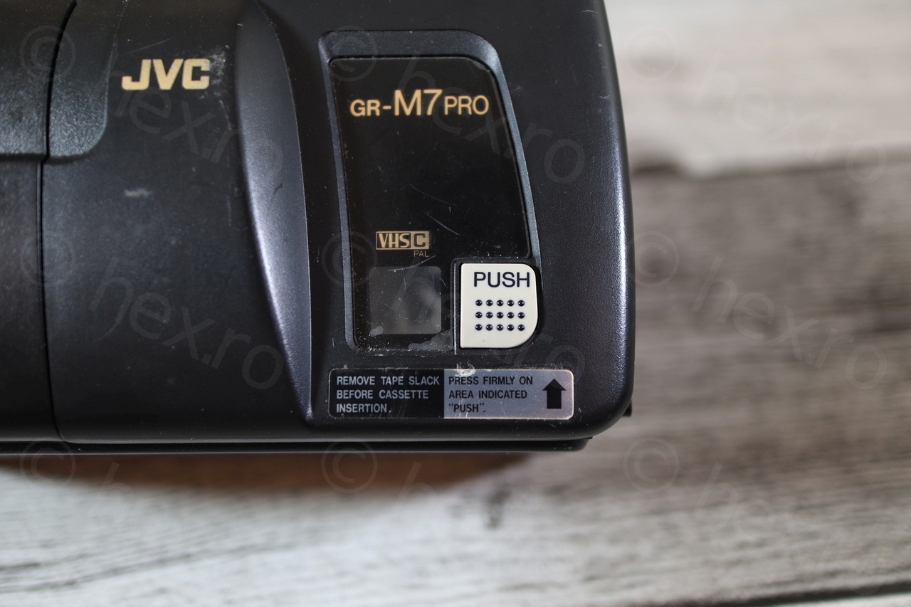
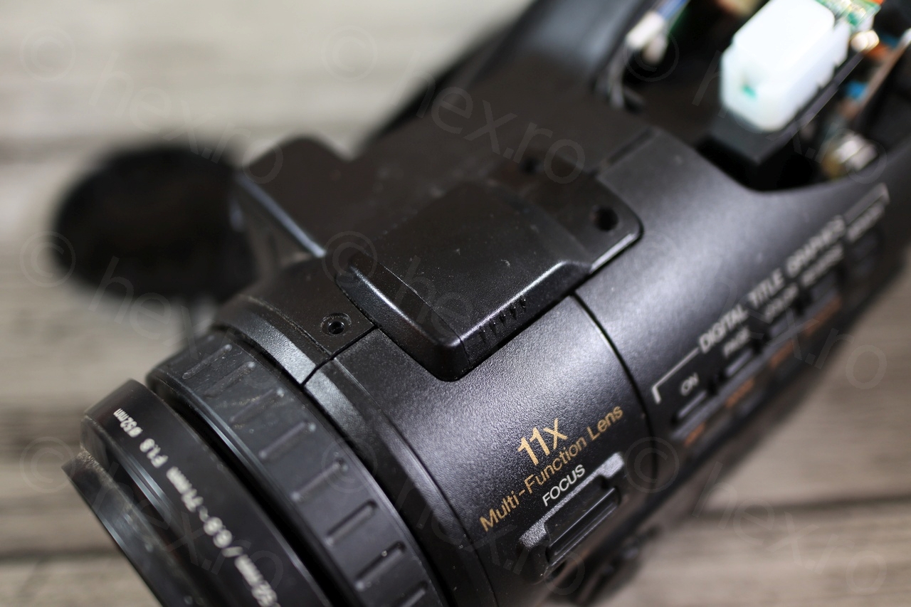
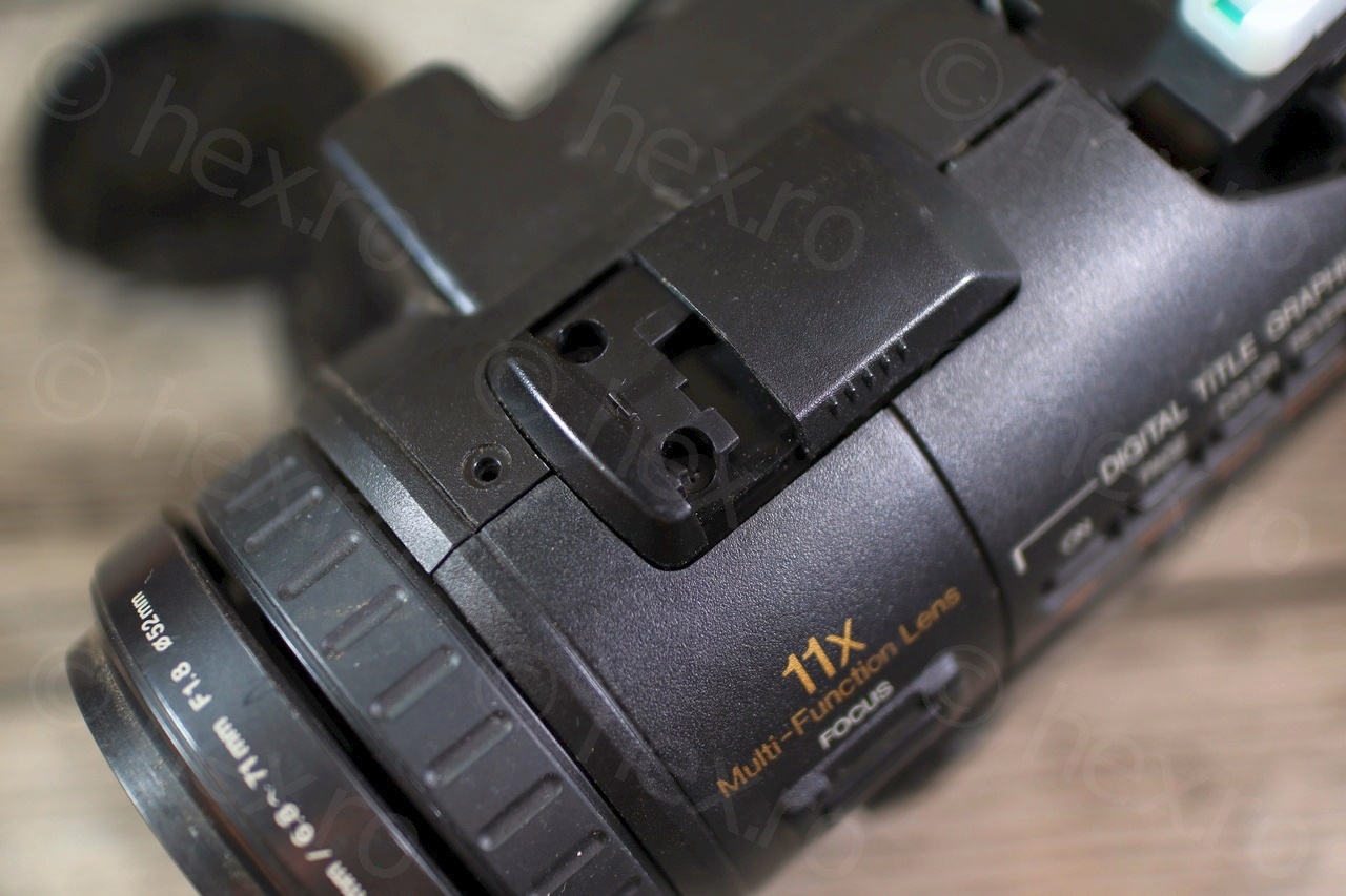
Continuing to take the camera apart, I was able to identify a hidden screw under the ‘PUSH’ button, and 2 more screws on the top front of the camera. Due to the age, that top sliding access panel was hard to move, it didn’t appear that it can be slid.
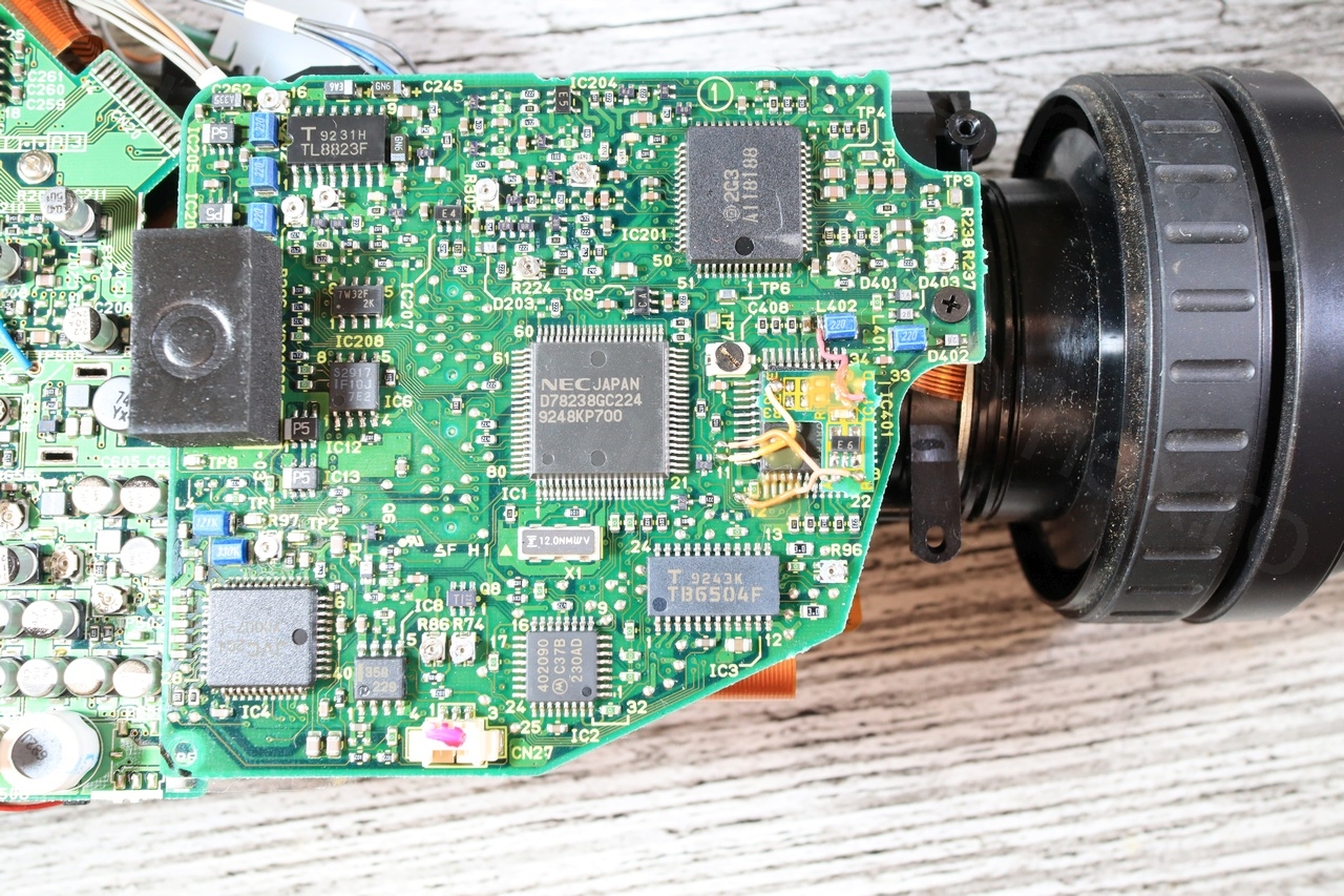
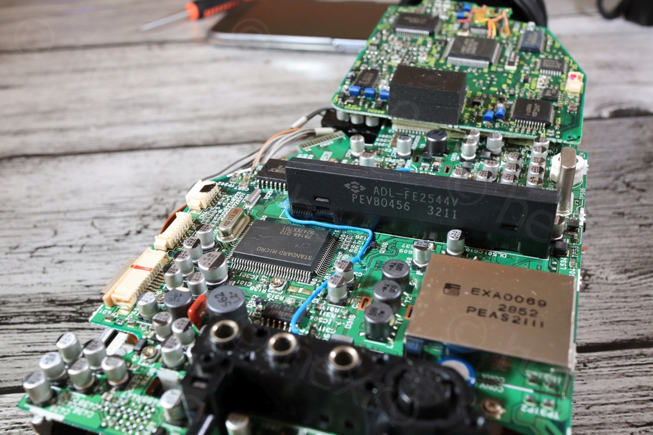
Once the camera apart, I am curious how the boards look like and see what I can salvage that could be useful. Lens are tempting, but sans idea what to do with them. Sometimes I keep weird parts or sensors, but this time, I was surprised to find out many obvious bodges that look added afterwards. The work is manual for sure, thus, I am wondering how many cameras were fixed like this, as it seems tedious to do – do I have a rare specimen ?
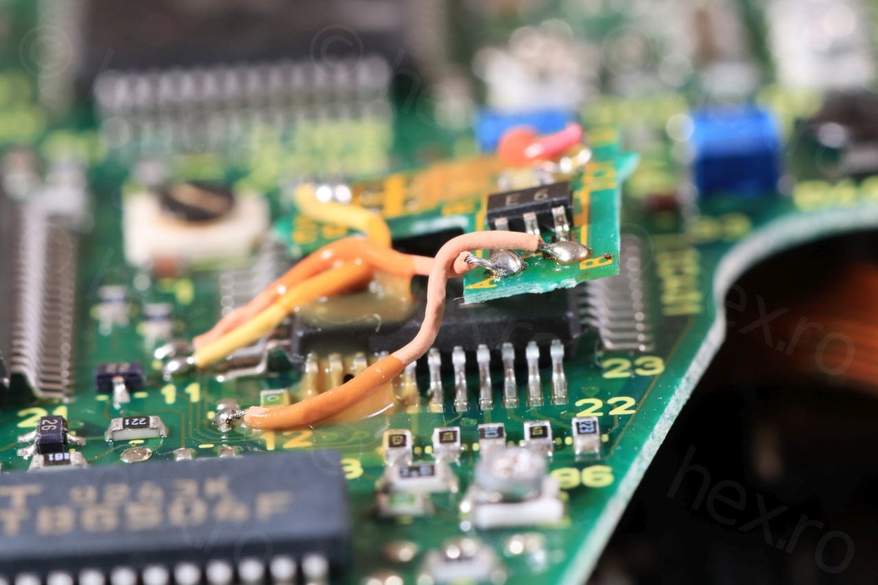
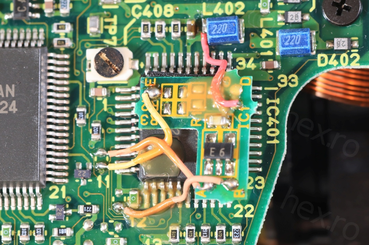
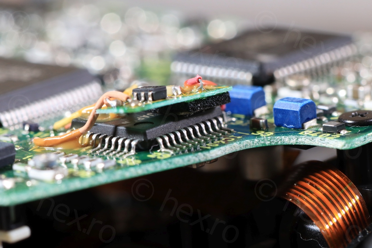
First bodge looks impressive:

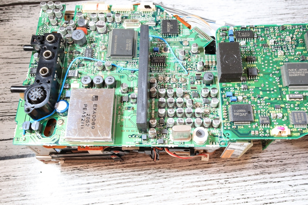
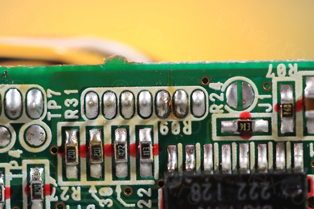
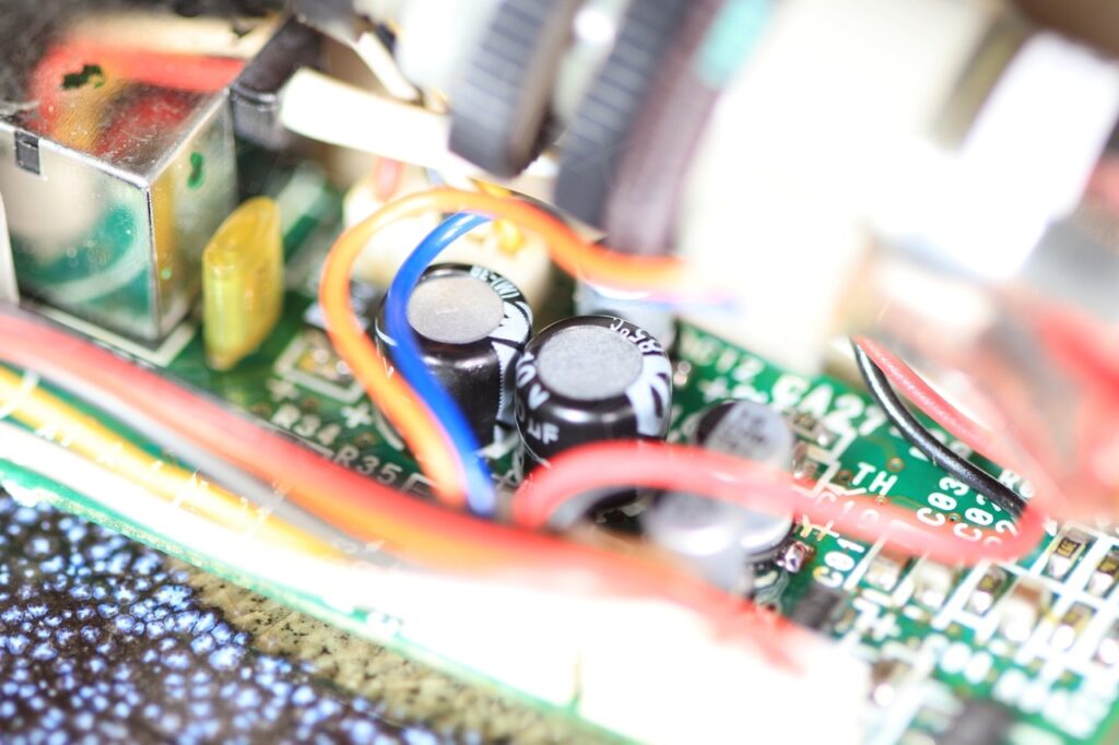
There are few more, such as this huge long blue wire:
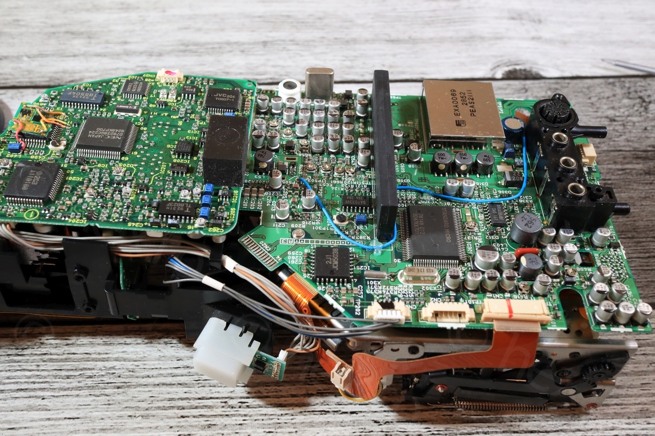
I found two more bodges on the underside of the motherboard – a resistor with yellow sleeves and another long magenta wire:

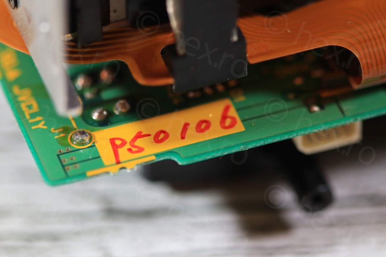
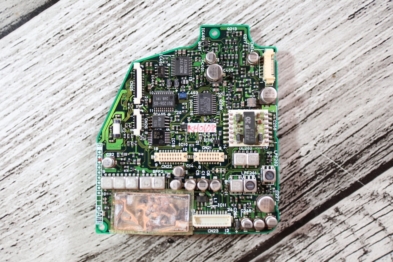
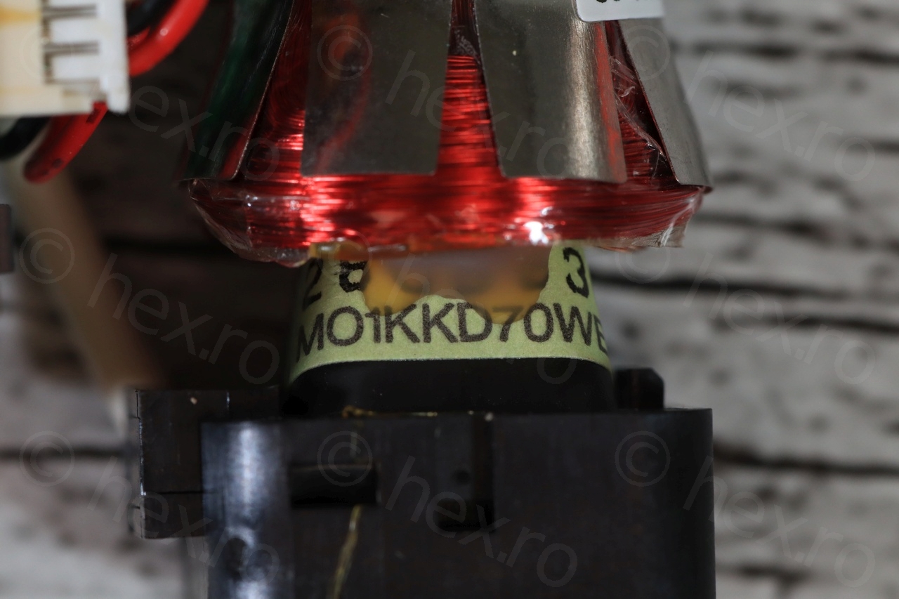
Very interesting to find also some handwriting inside, it almost feels like message in a bottle 🙂 Thus, the camera seemed to have been assembled after January 2008. One marking says P50106 and another one, in the middle of the board on the right, says KH0108:
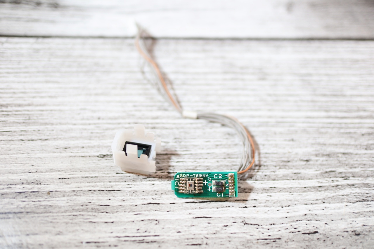
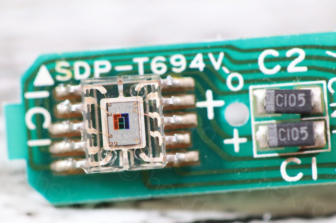
Related to parts that I could salvage, I isolated this RGB sensor which I decided to keep (probably used for white balance). Not able to source a schematic for it though:
CRT
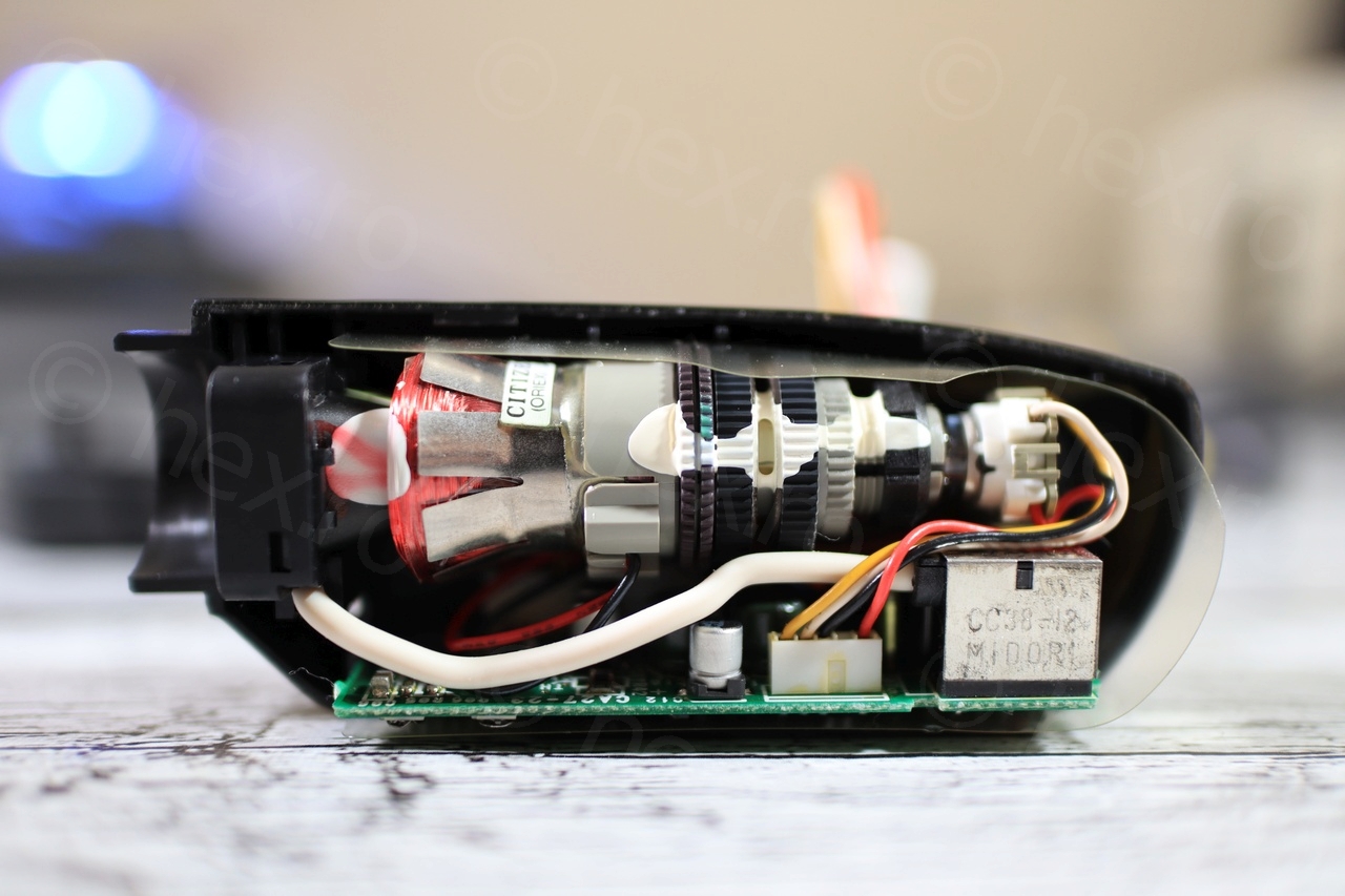
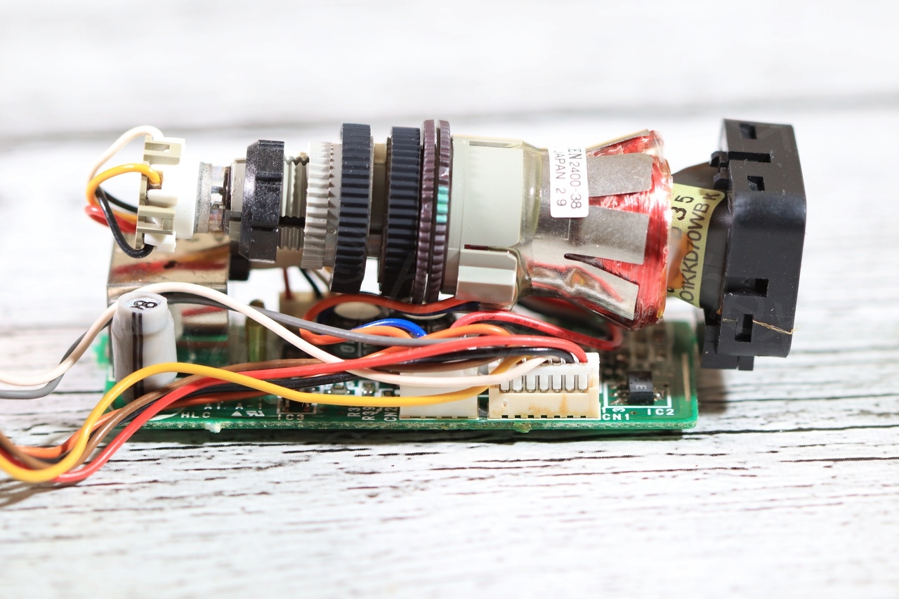
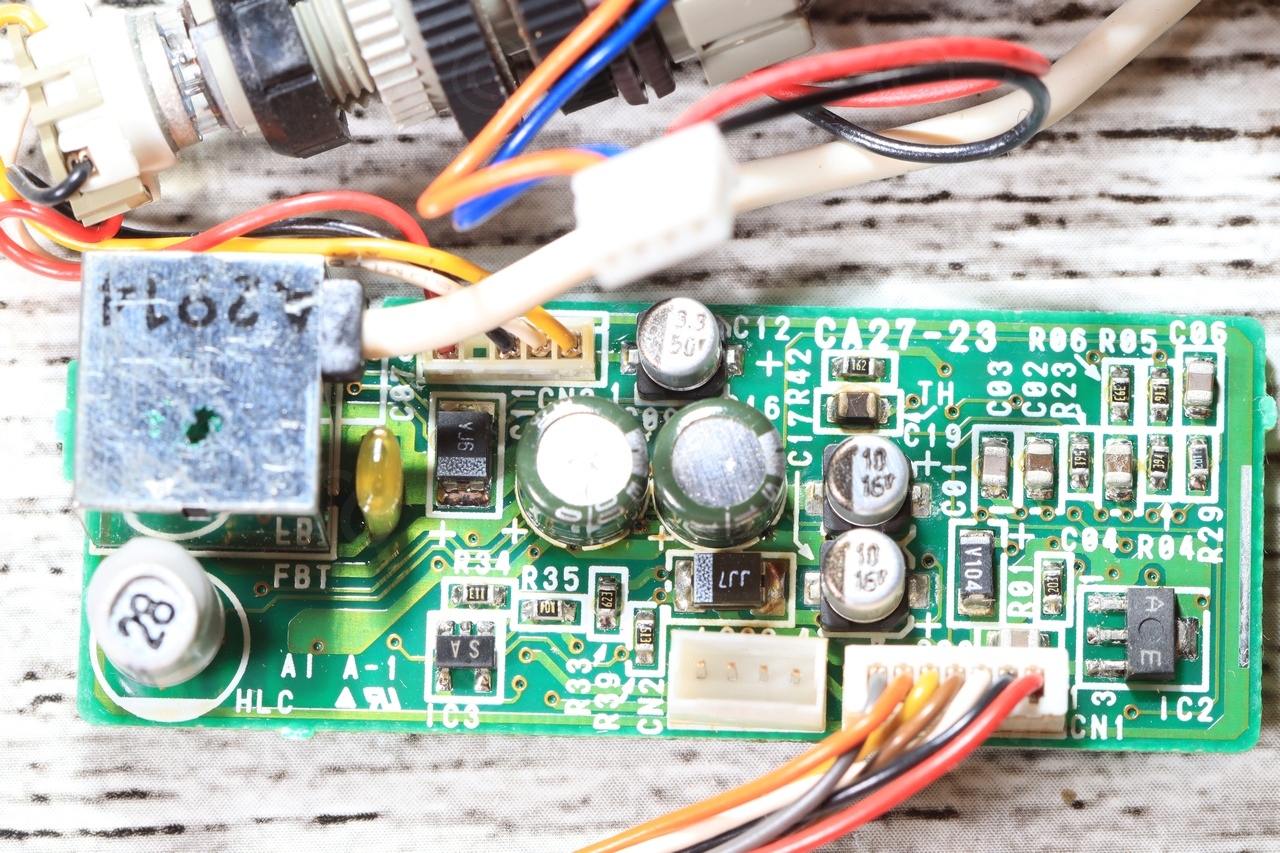
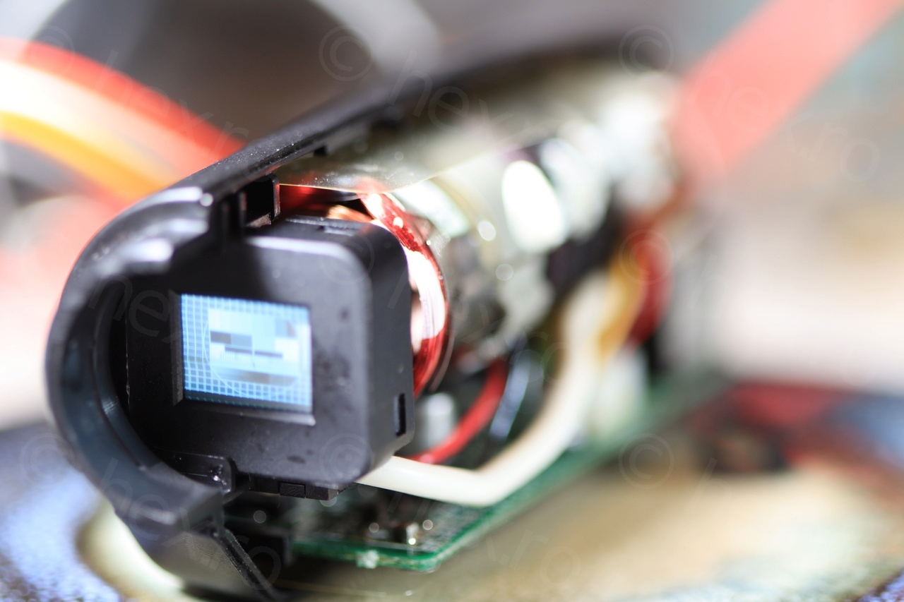
Once the camera tear-down finished, I was able to focus on the CRT and trying to identify the signal pins. First an overview:


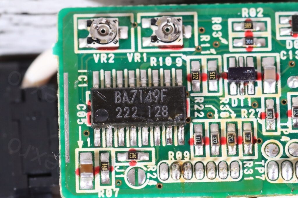
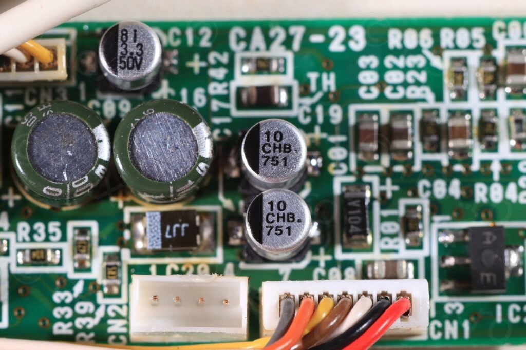
The core of the driver board is BA7149F chip:
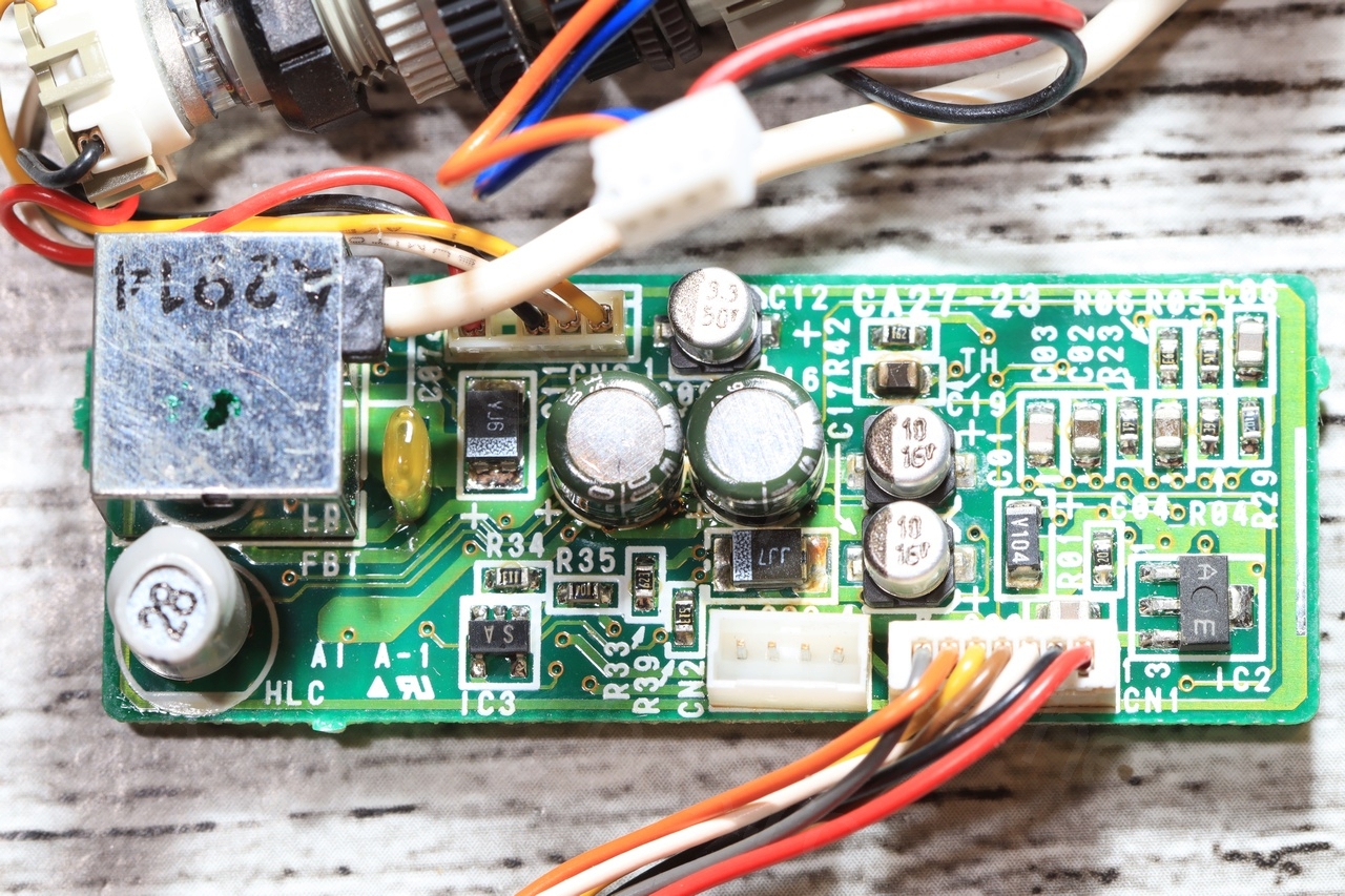
Even if I already encountered this one on the other boards, there were changes in the standard BA7149F connection diagram. I would expect its PS1 pin (pin2) to be connected to Vcc but it is not. I found that PS1 pin is connected to IC2 (A/E) component (lower right in the image below) which itself is connected to CN1 pin (the connector to the Camera motherboard). IC2 is connected to the RED cable, thus (and it makes sense), the RED wire is Vcc:

BA7149F has an additional Power Supply 2 pin (pin 12), but the meter beeped when checking continuity between this pin and the main Power Supply 1 pin. However, the reported resistance was non zero, but small enough. I decided not to power PS2 (as it appears unconnected in the connection diagram of BA7149F).
Identifying the GND pin is easy, the Brown / Black wires of CN1 have direct path to the shield of the Fly Back Transformer. Weirdly, the CN1 connector on the camera motherboard had the Black pin unconnected, thus leaving the brown pin as a GND connection.
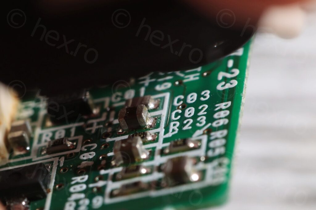
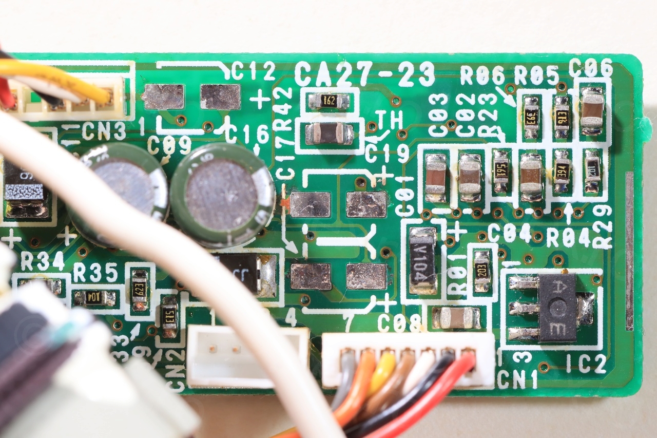
Identifying the Video IN signal was easier than expected, but again, thanks to the driver board not following the standard connection. The VIDEO IN signal is supposed to arrive to pin 11 via a resistor divider:
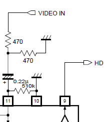
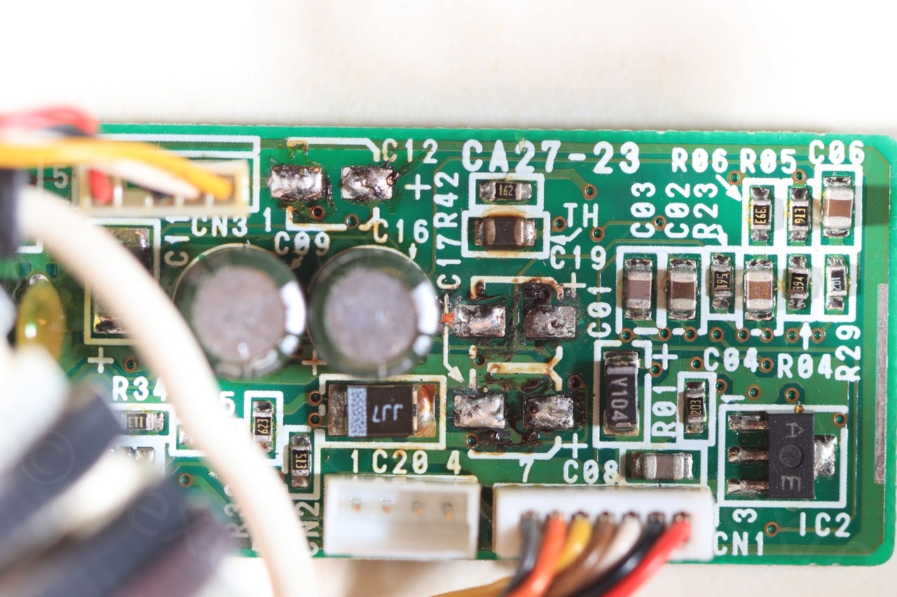
This is not the case; using the continuity meter, I traced pin 11 to C02 capacitor (photo below) which, in turn, is directly connected to the WHITE cable on CN1. It may also be that the resistor divider is present on the Camera board where CN1 connects, but I did not check.
Conclusion is that the 3 signals Vcc, GND and VIDEO IN are present on the RED / Brown / White wires going to the CN1 connector.
Powering on the EVF
The first signs of trouble appeared when trying to identify the signal pins – brown / dark yellow spots / streaks on the board:
I’ve tried to use a very cheap ESR meter to measure the electrolytic capacitors – 5 of them in total. The 3.3μF cap was detected as 29pF, and one of the bigger 100μF / 10V was was reported as no part.
I decided to power own the board just to see what happens, the result is below. Most of the CRTs are supposed to show a brighter ‘idle’ image (when no video is connected) but this one went directly to almost OFF in less than a second after Power ON. I’ve tried to see (even in dark) if its lit, but obviously something was wrong with it.
On top of that, I felt a weird smell after few cycles of on / off (I guess the smell of dead caps ?).
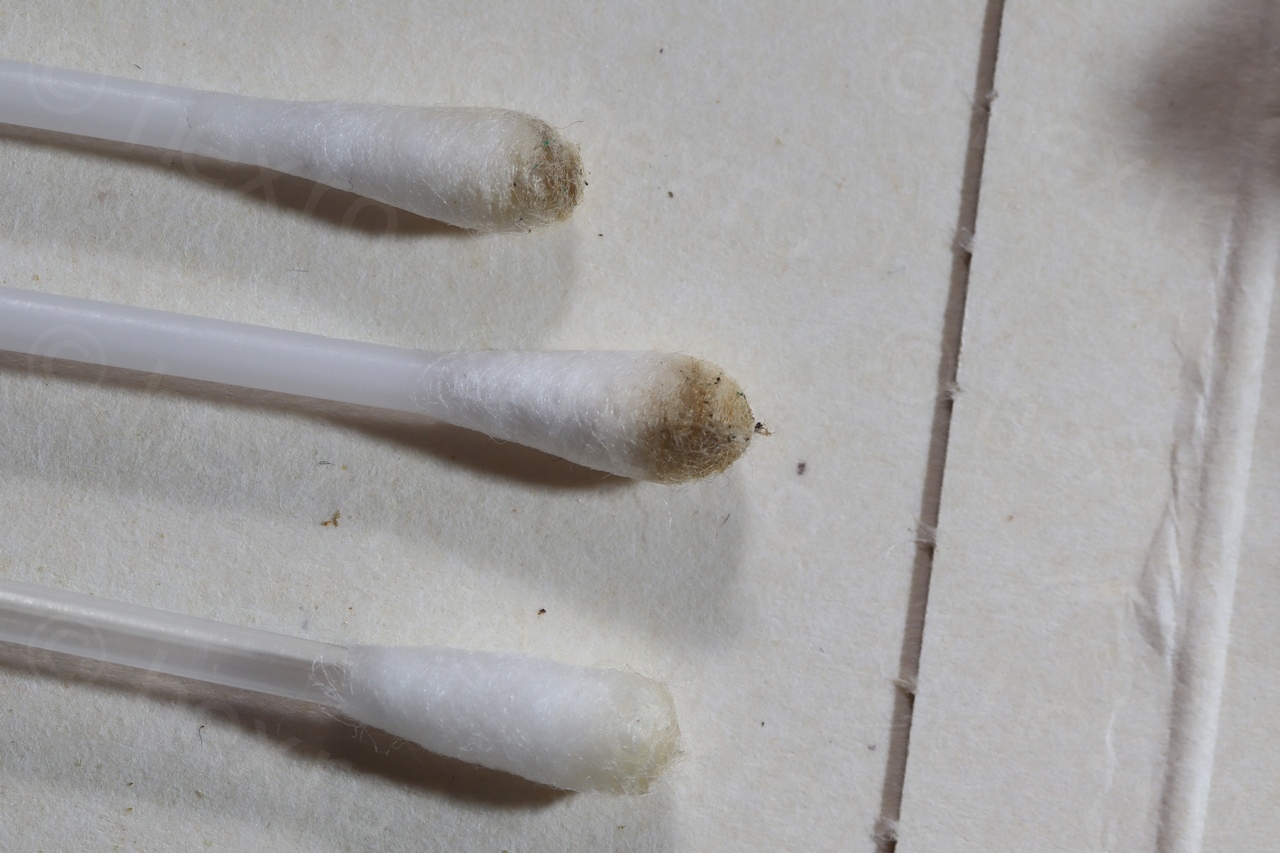
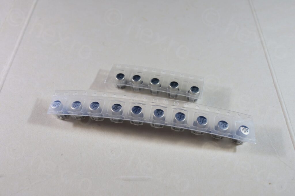
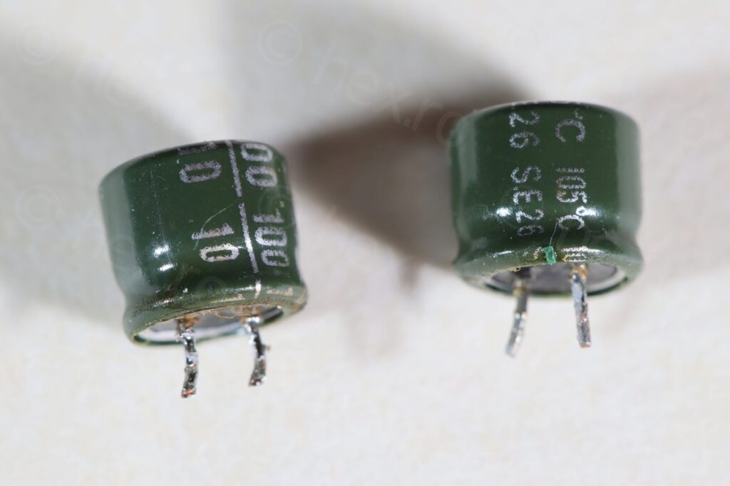
I decided to remove the small source mounted electrolytic capacitors (3.3μF@50V, and 2 x 10μF@16V). I have also cleaned the board with isopropyl alcohol – it was very dirty, plus took time to order new parts including the bigger the two 100μF@10V through-hole ones. Tricky to order due to the size requirements (they were all 5mm tall).

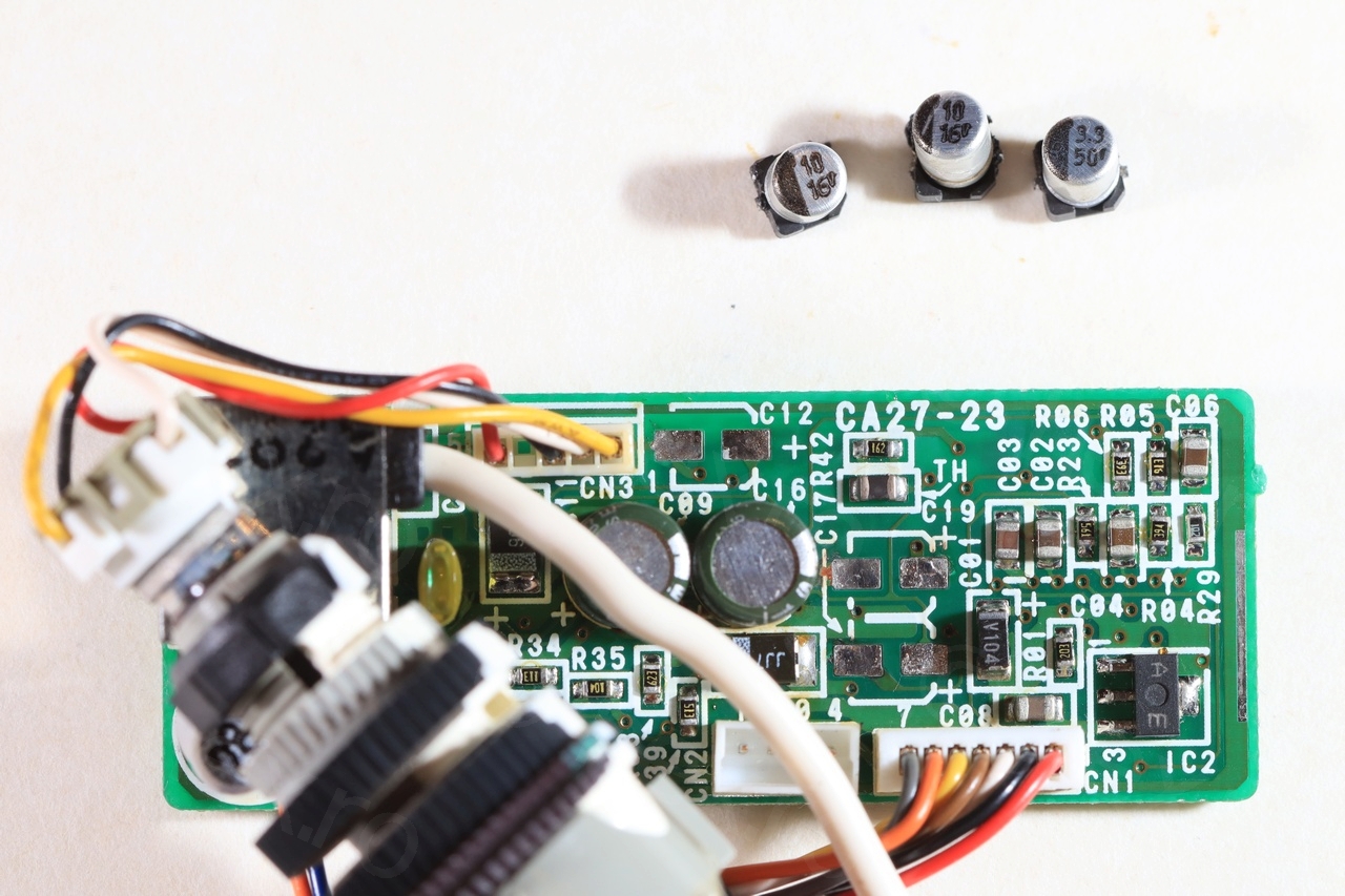
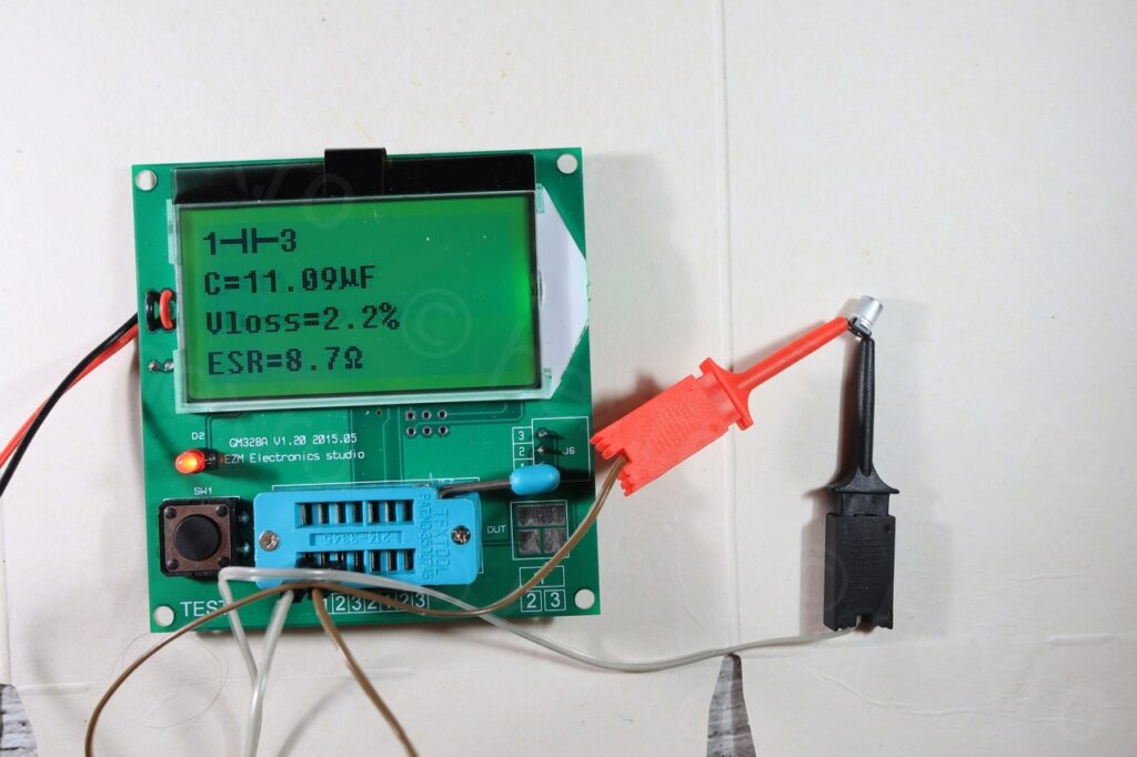
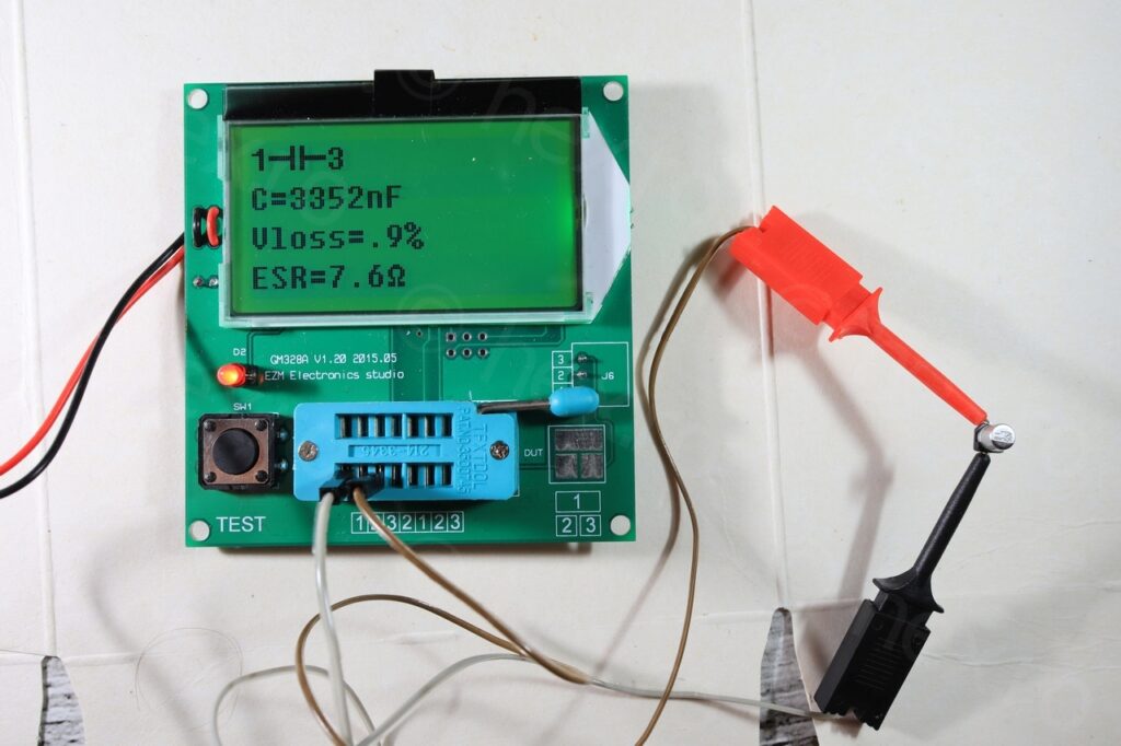
I decided to use the ESR meter to check the three capacitors now they were out of circuit (the first ones that I suspected are problematic and that leaked, as the gunk was around their side, especially the 10μF ones in the center).
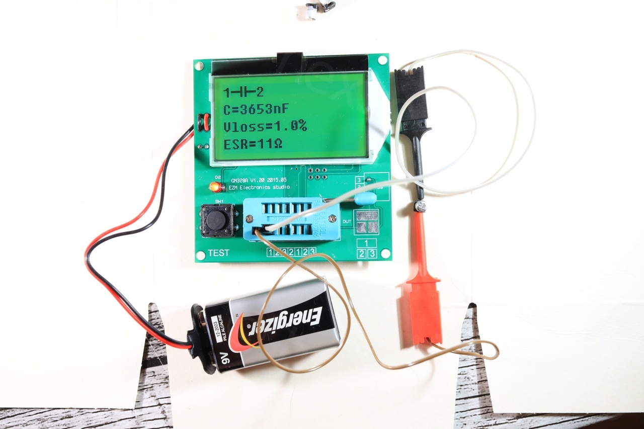
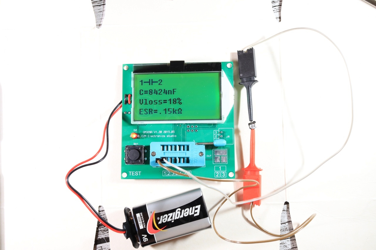

The results were that the 3.3μF cap measured OK, but the two 10μF ones were dead. One measured 8.5μF but had 150Ω ESR, the second one was totally dead.
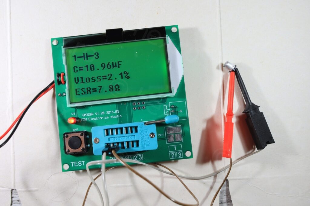
While the three caps went out, I decided to do an in-circuit testing of the remaining two caps; surprise, they reported good values (although a little higher ESR).
Waited for the new parts to come in and proceeded to solder. I’ve measured the new ones (also as a mean to cross check the ESR meter) and all was good, thus, I proceeded to re-solder them. I have to buy a much smaller soldering iron tip though!
I was undecided if I should replace or not the remaining two bigger caps (through-hole), but since the board was already ready to work on – I figured why not.
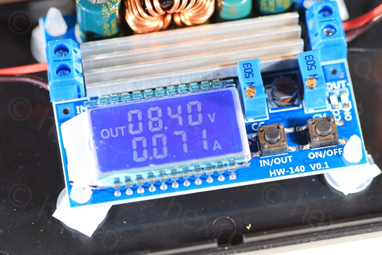
After all the love and care, the little CRT came up alive 🙂
It doesn’t look as sharp as other CRTs even if I tried various voltage inputs. It is not bad, but not great either. I settled at 8.40V and it draws about 70mA.
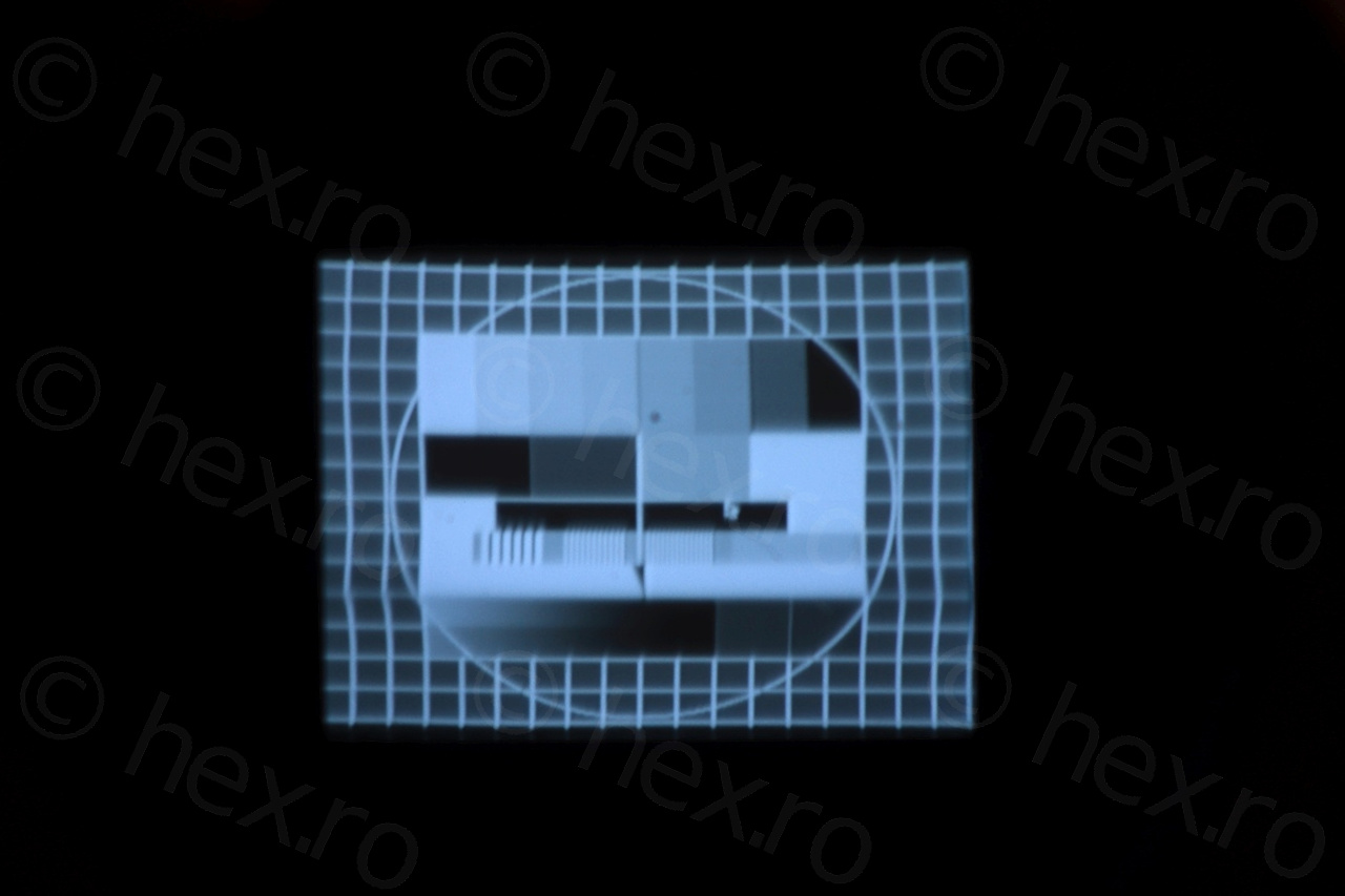
And of course, Manic Miner 🙂
Looking forward to dismantle new cameras,
qf
Heh – thanks for sharing 🙂
I have an almost identical CRT (marked Citizen 2400-11) from a Sony camcorder. The tube looks identical but the driver board has a different layout and a light guide for the record LED.
The driver module had no leaky caps but the camcorder definitely did.
I also have an easier time in driving mine, as I think that the four wires are simply
+
–
Video
…and record LED, I think
I, too, look forward to getting my hands on more.
Dan
Hi I just took apart an old GR-M7E and it has the exact same bodges on the boards!