


Introduction
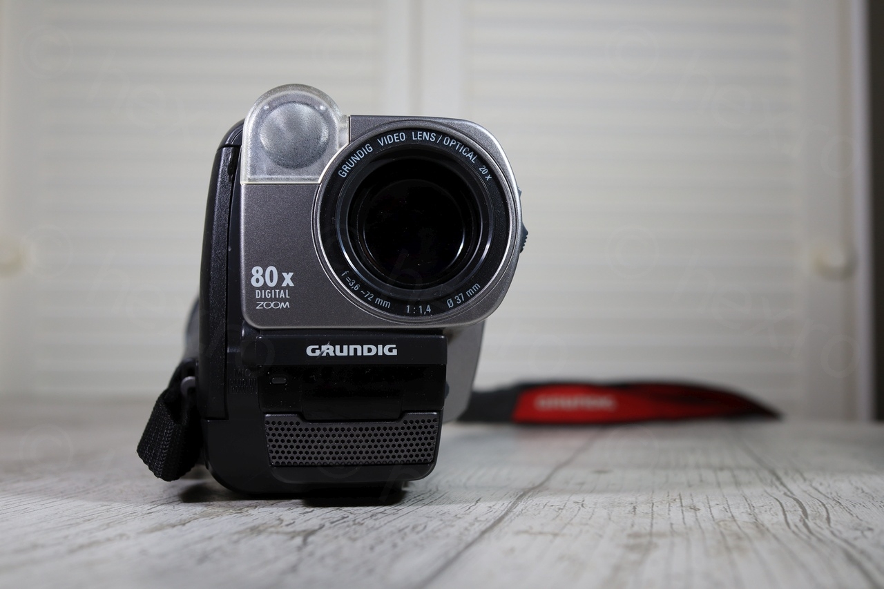
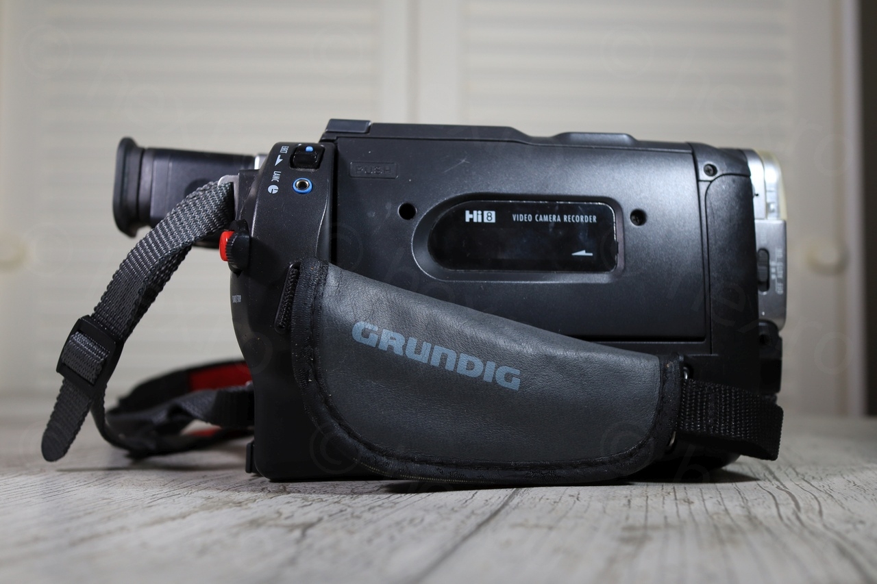
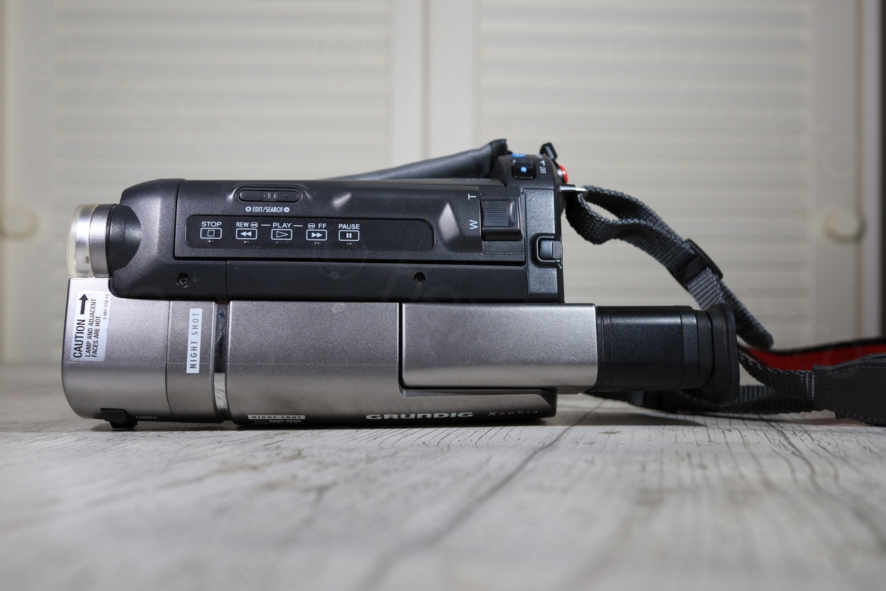
This mini CRT part of a Grundig LC 5000 HE camcorder.
Camera tear down
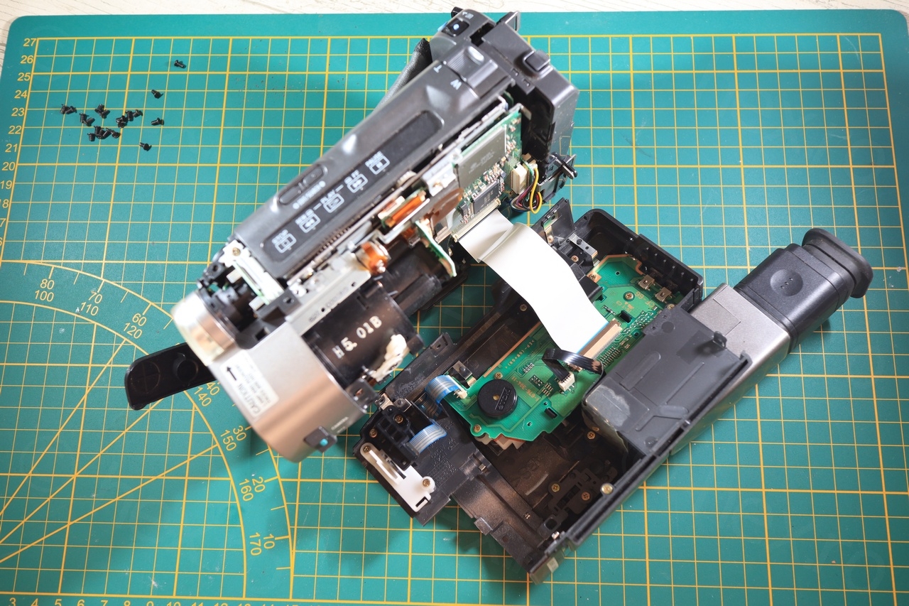
Opening the camera was a pleasure. Very easy to tear down and modular, once the screws out, the plastic covers came apart without prying too much. Not to mention that Grundig used same screws everywhere.


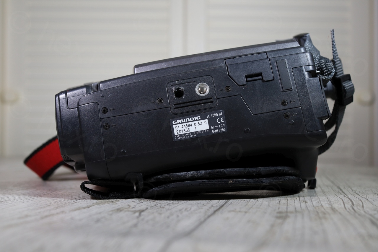
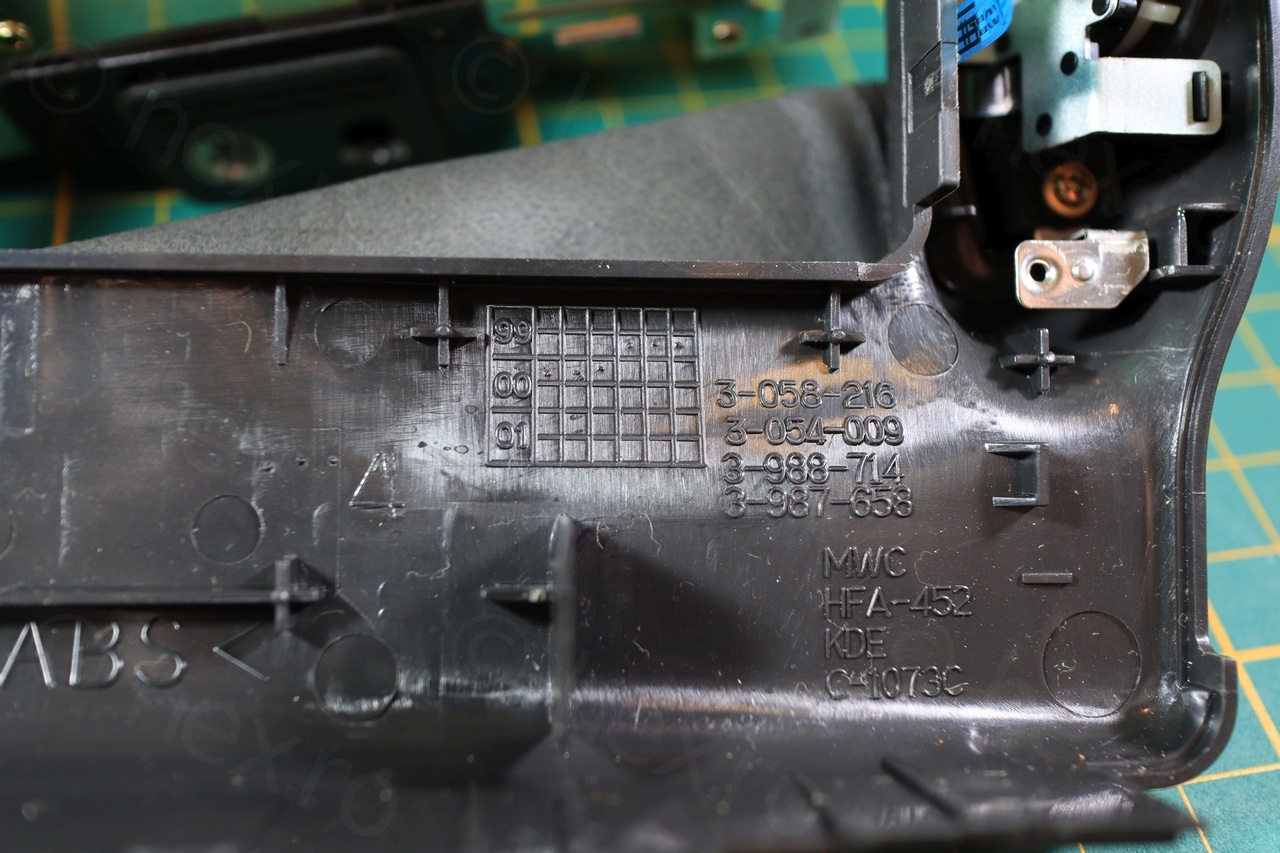
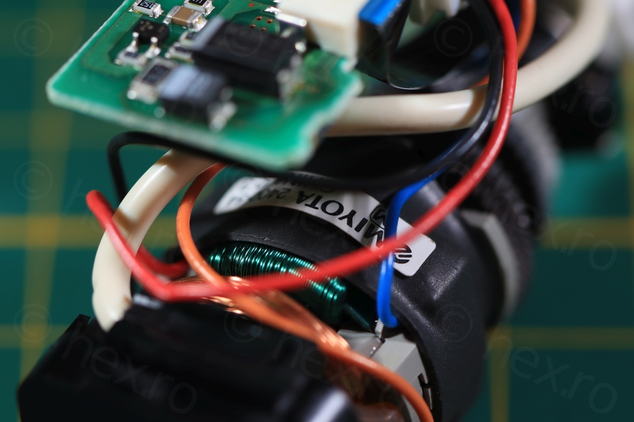
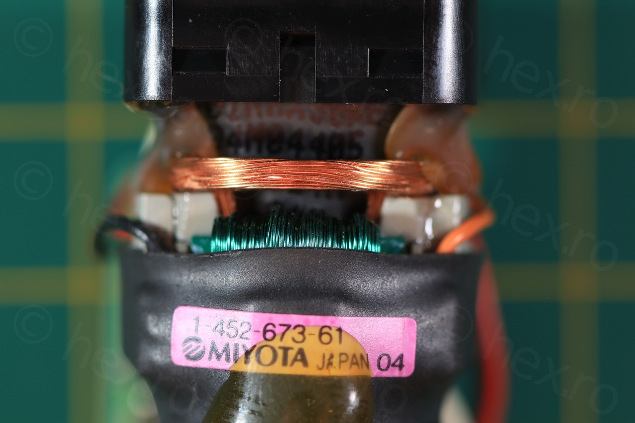
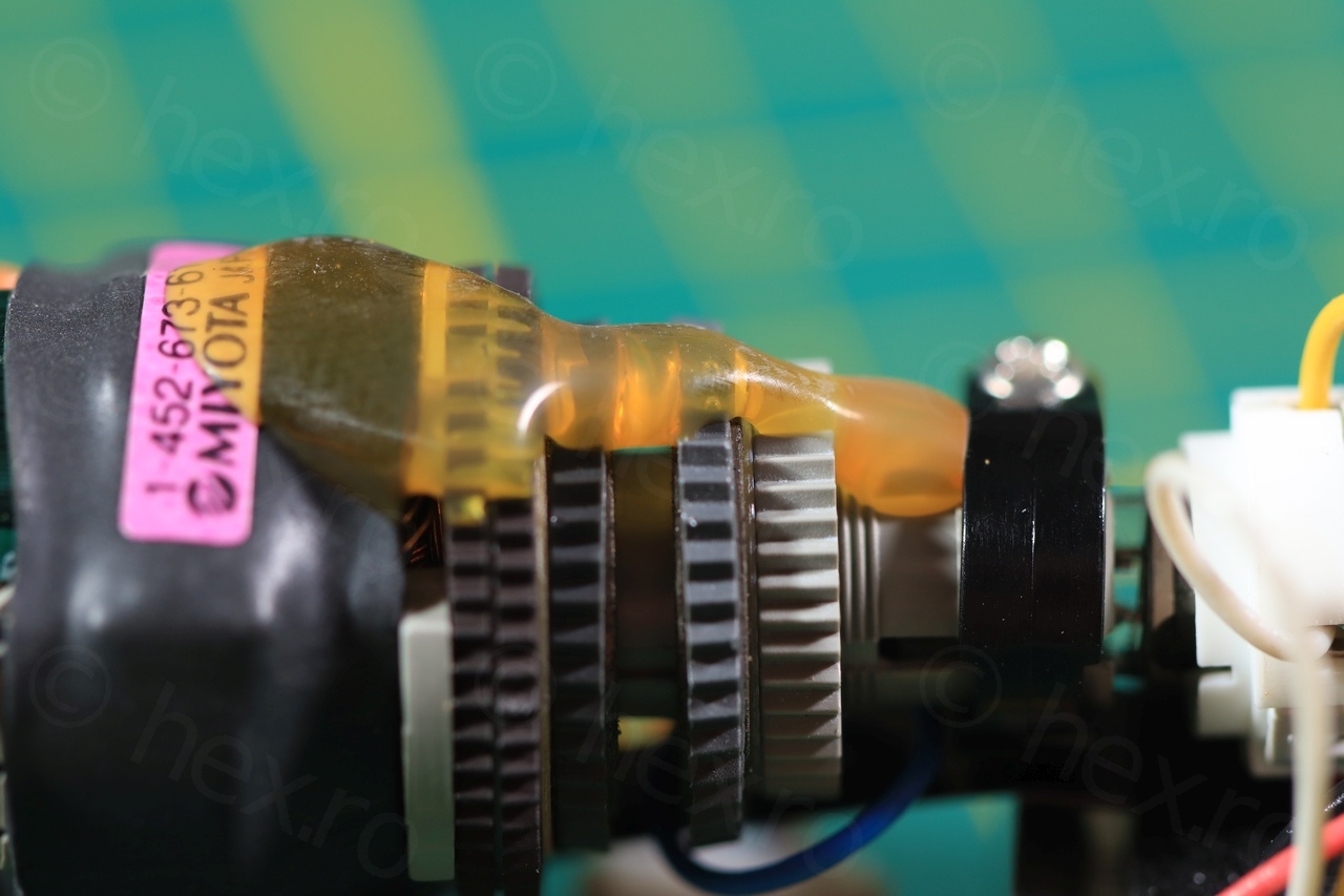
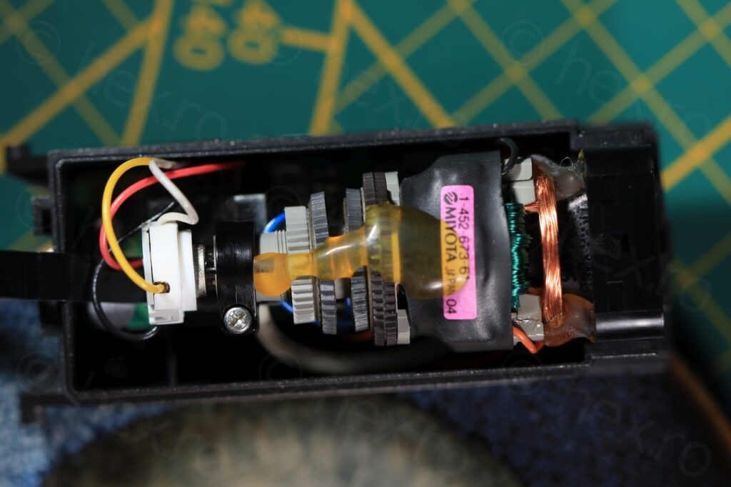
Having a look at the EVF compartment, there are already good news, only 4 wires going in, thus finding out the Video IN signal would be easy. Camera seemed to have been made towards end of 1999 and beginning of 2000, given the stamps on the inside of the plastic case:
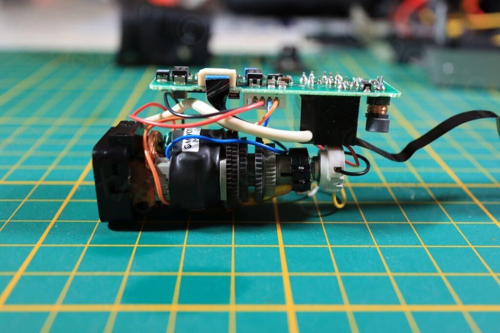
The Electronic View Finder unit has a nice sliding movement that I decided to keep.
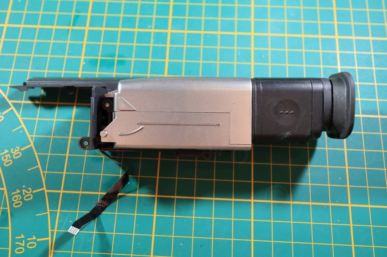
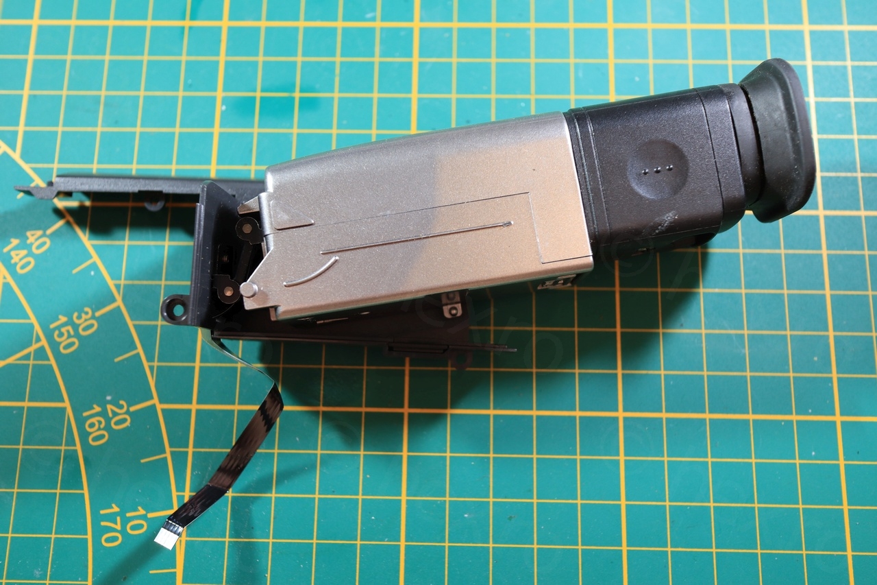
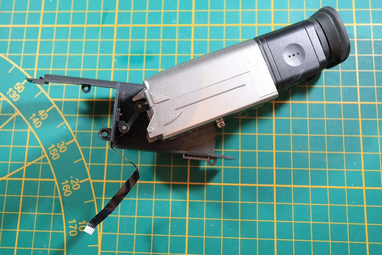
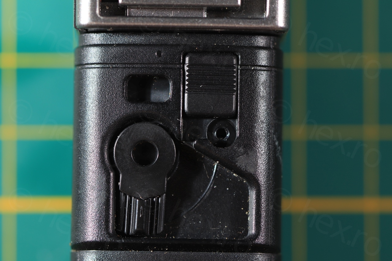
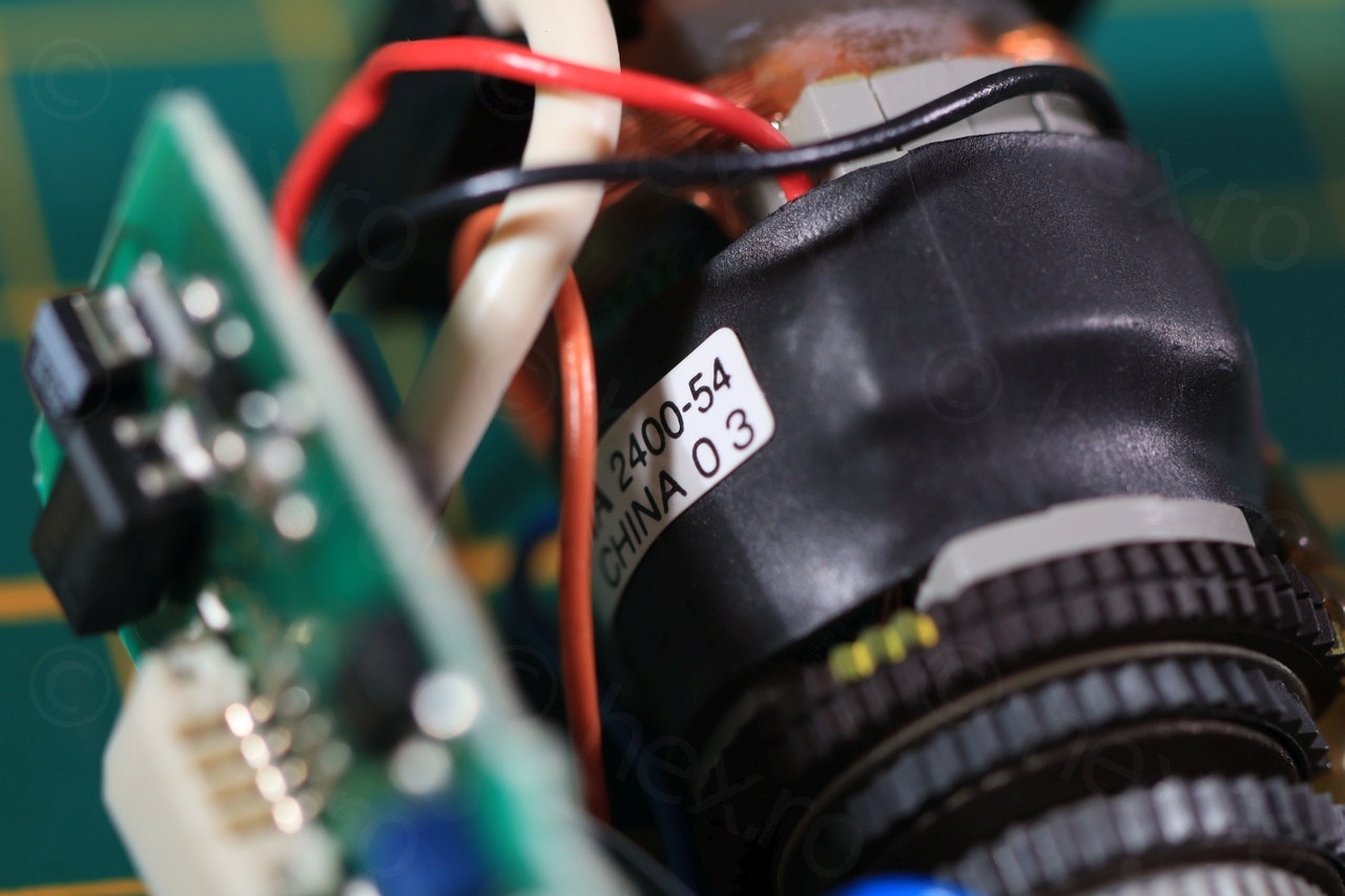
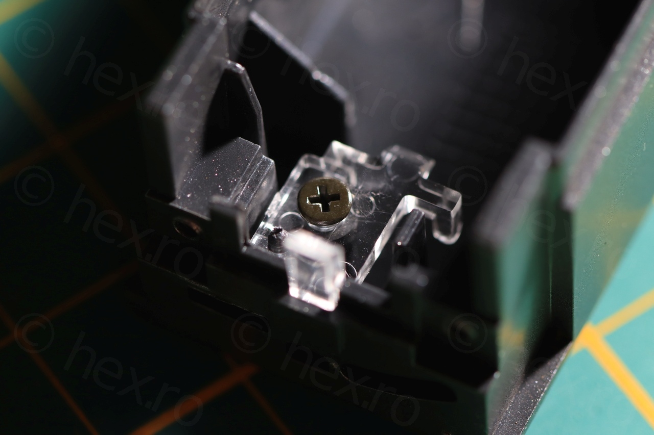
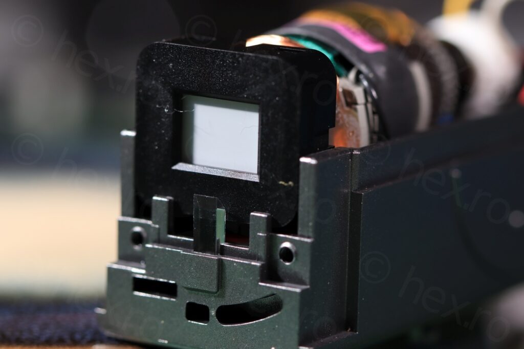
Dismantling it though was a different story. I could not see how to take apart the lens barrel, on most of the EVFs, the black barrel would just rotate away but not here. On closer inspection, there was a slider on the underside that was blocked by a screw. Once the screw out, the slider pulled in a latch that allowed the barel to rotate away from the body of the EVF.

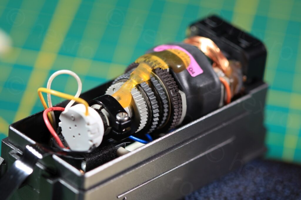
Once inside, again, very surprised by the miniature driver board. I think it is the smallest by far, the components are so few that it feels this is just a reference implementation of the BA7149F chip!
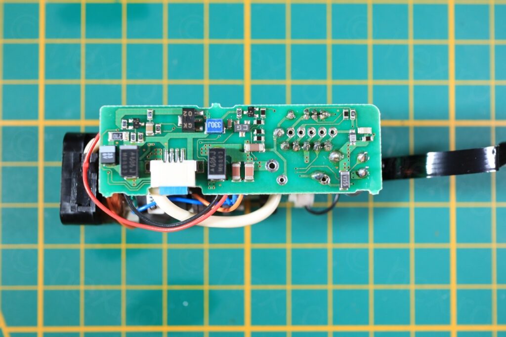

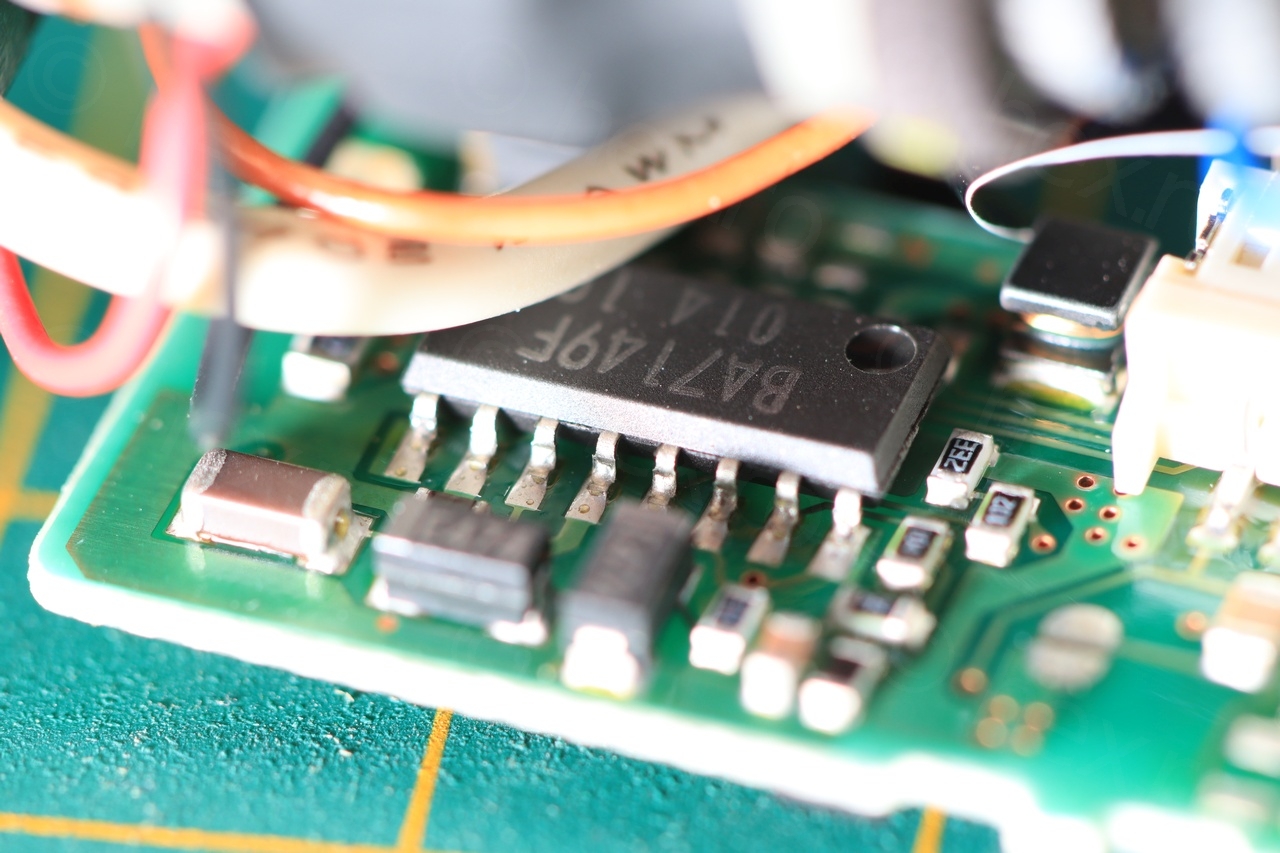
More closeups as I was impressed by the minimalism of the driver board.

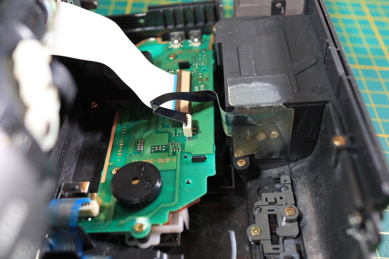
I had to desolder the connector of the EVF cable from the camera’s motherboard. Using the heat gun set at 300C with a medium sized nozzle, the connectors can be pushed away after about 1 minute of heating the sides. I prefer to push them away as I feel that grabbing with tweezers may deform the heated plastic, and if they spread a little solder around – no problem, the camera motherboard goes to the recypark anyway.
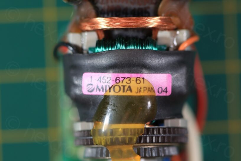
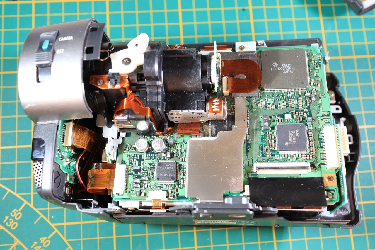
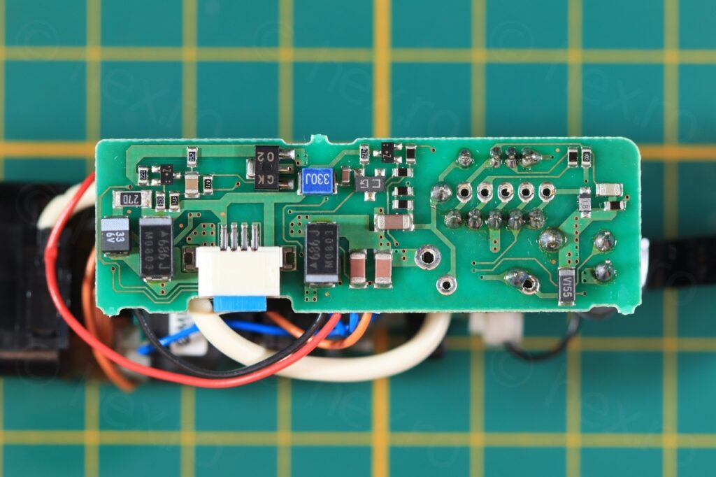
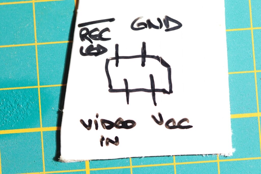
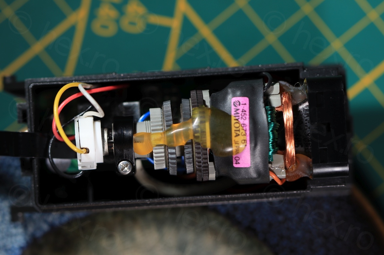
Once the connector out (first picture below), I was able to start probing. I quickly identified the GND connection (as it is present on the shield of the Flyback Transformer, the biggest ‘cube’ on the driver board). The FBT also has a shared pin with the VCC (in most cameras anyway), and thus, identifying the VCC was also easy, is the only pin of the FBT that has continuity with anything else on the input.
The Video IN was found by trying the remaining two PINs with a Video IN signal.
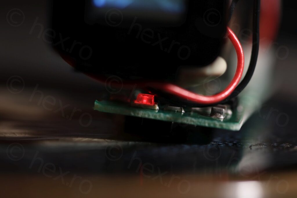
I was curious about the 4th remaining wire, what could it do ? I have observed that the plastic housing of the EVF has a transparent plastic part which and it made me realize there is a recording led inside. I have tried to turn it on using VCC but it would not work, but trying to connect the 4th pin to GND turned on the recording LED. Thus, I called the 4th pin to be the ‘REC LED’ (active low).

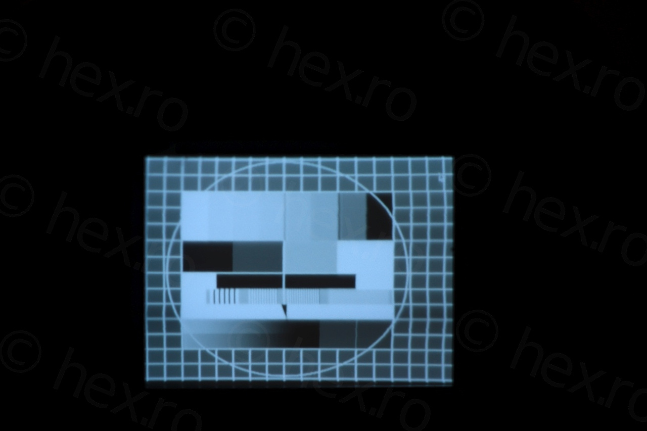
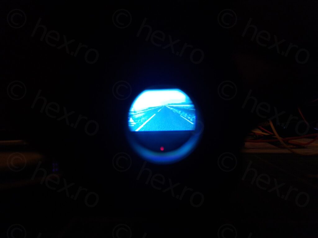
Once pins identified, time for some tests! The sharpest image seems to be at 5V, and the mini CRT draws 100mA of current. The image is slightly shifted left (compared to other mini CRTs I have tested) but I am happy it still works.

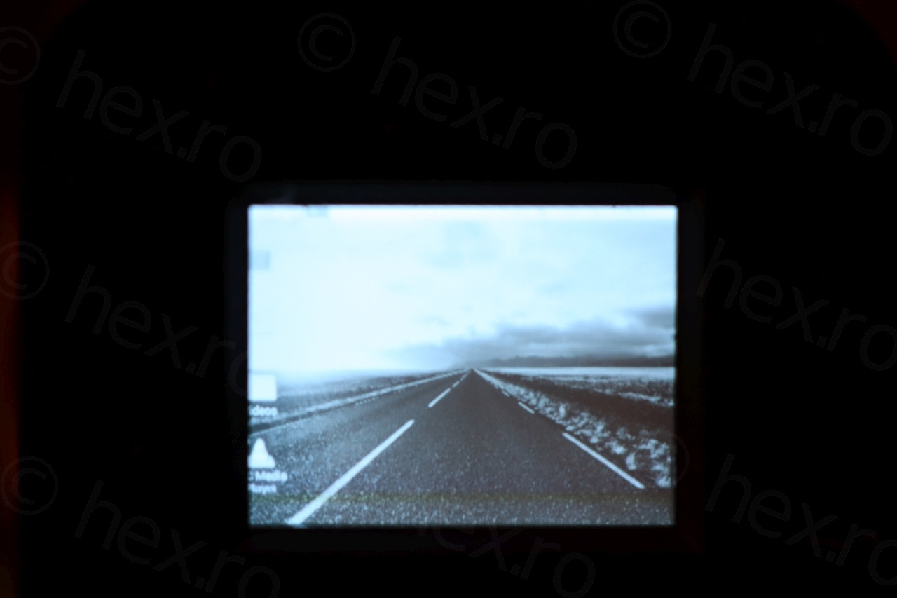
Of course, I wanted to record a session of Manic Miner:
Closing with few more macro shots of the reassembly, including a photo taken with the mobile phone, where I was trying to show the recording LED also on.

Recording LED on.


This was a fun tear down without any dramas .. plus, I started to become curious of what do other wires do, on the EVF connectors ?
leqso bitadze
I did everything like you. I have an image but it is too blurry, what can I do?