Now that I finished fixing this Sinclair ZX Spectrum 48K, I feel a little tired and not sure how to start describing it, nor how long the article will be.
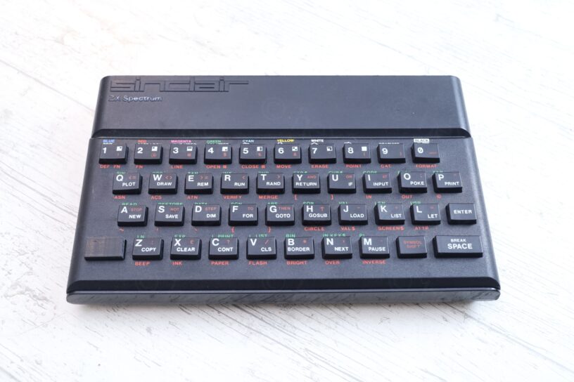
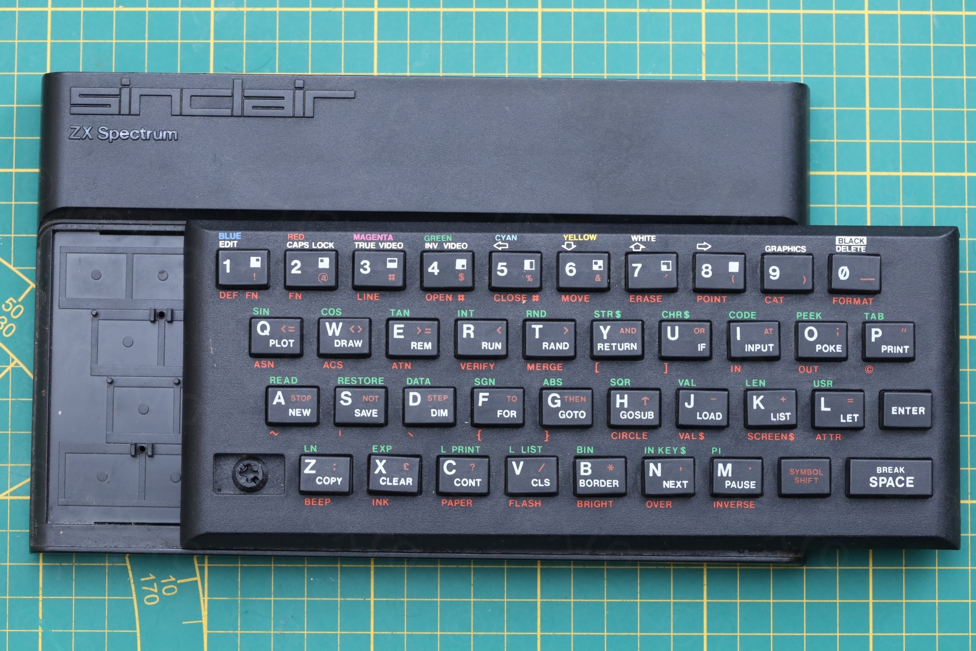
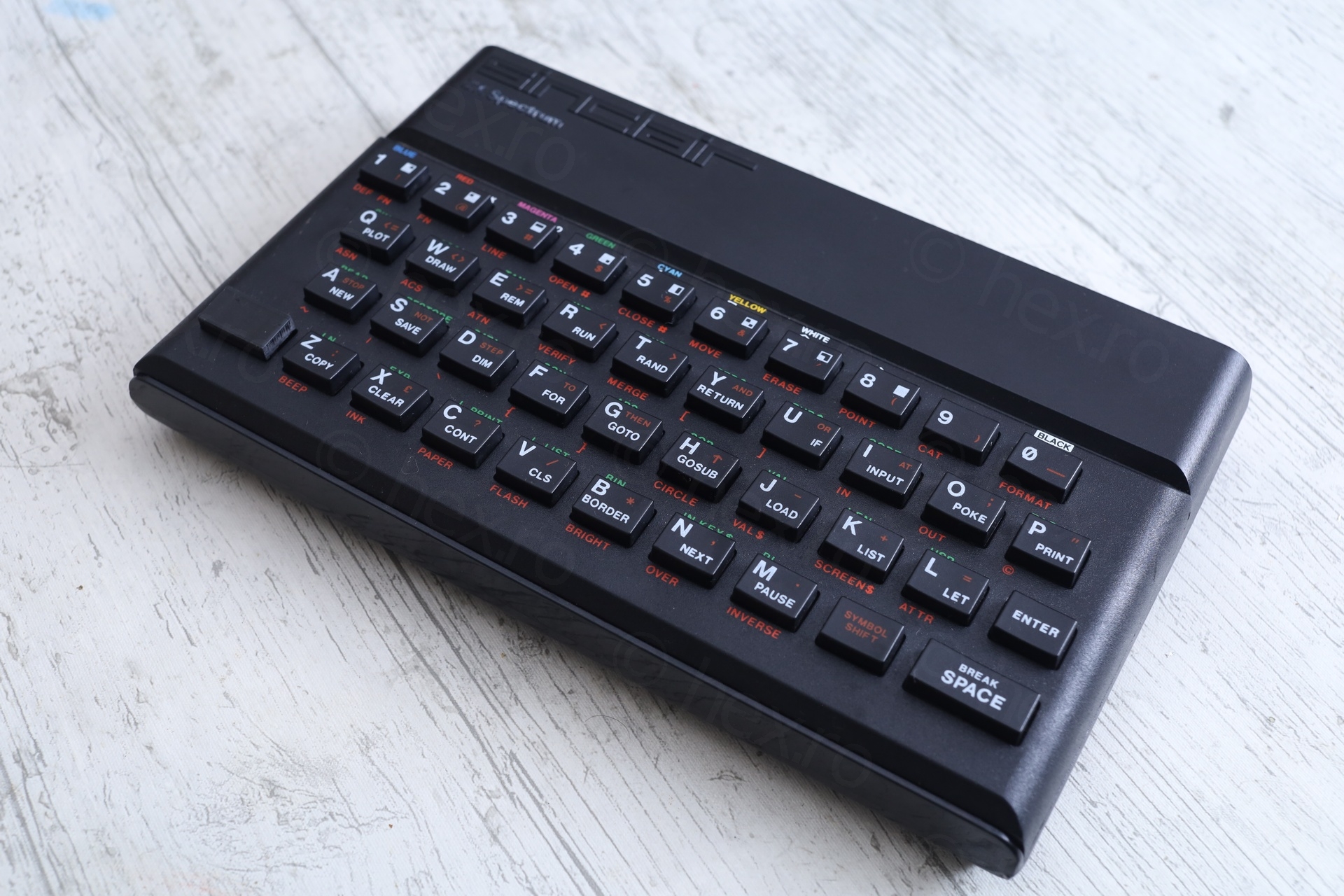
I bought it off EBay. While I saw the missing the CAPS button – I brushed that off as a rubber key mat replacement. Only after receiving it a week later, I discovered this computer has a plastic keyboard. I was confused at first.
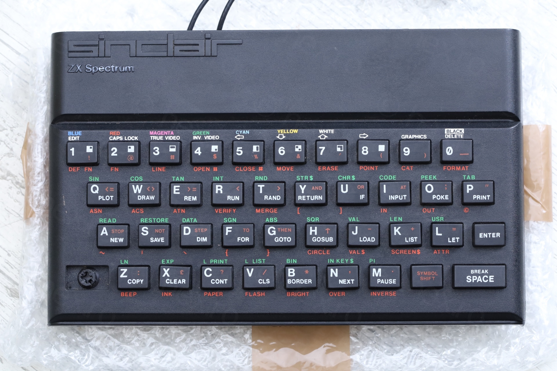
Few thoughts were swirling fast in my head. How come is plastic, I thought is just a rubber keyboard mat replacement ? It really looks made for Spectrum, with printed lettering, this can’t be 3D printed ? Was I cheated ? What is this thing ?
I first went to the listing, and yes, it was clear. The photos were very dark. This keyboard looks so close to the original, I just assumed it is the normal rubbery key type. Swirling calmed down a bit, replaced by curiosity. What is this ?
There is a single mention of this keyboard on the internet, found here : https://k1.spdns.de/Vintage/Sinclair/82/Peripherals/Keyboards/Teclado%20meca%CC%81nico%20(Timex%2C%20Portugal)/ and the info.txt is telling: the keyboard was bad, many were returned. Interesting.
Decided to repair this computer for two reasons – the keyboard and the findings inside. Somebody in the past went to great lengths to keep this computer running. It deserves to keep running.
Table of Contents
- Visual inspection (Outside)
- Visual Inspection (Inside)
- Power ON Tests
- Repairs
- Teclado mecánico
- Wrapping up
Visual inspection (Outside)
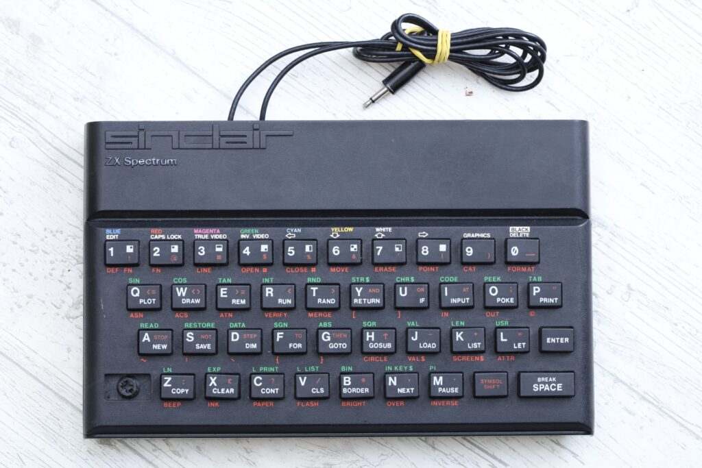
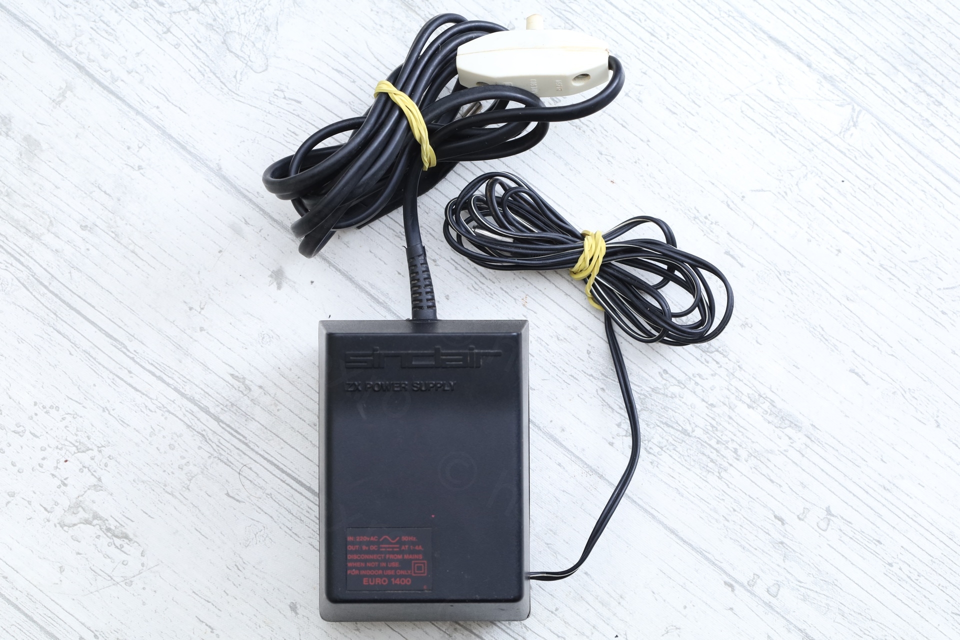
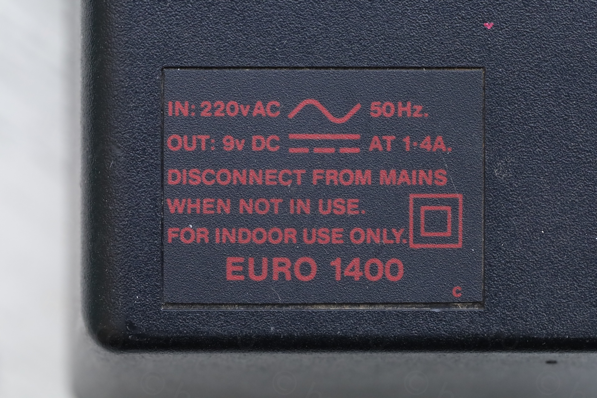
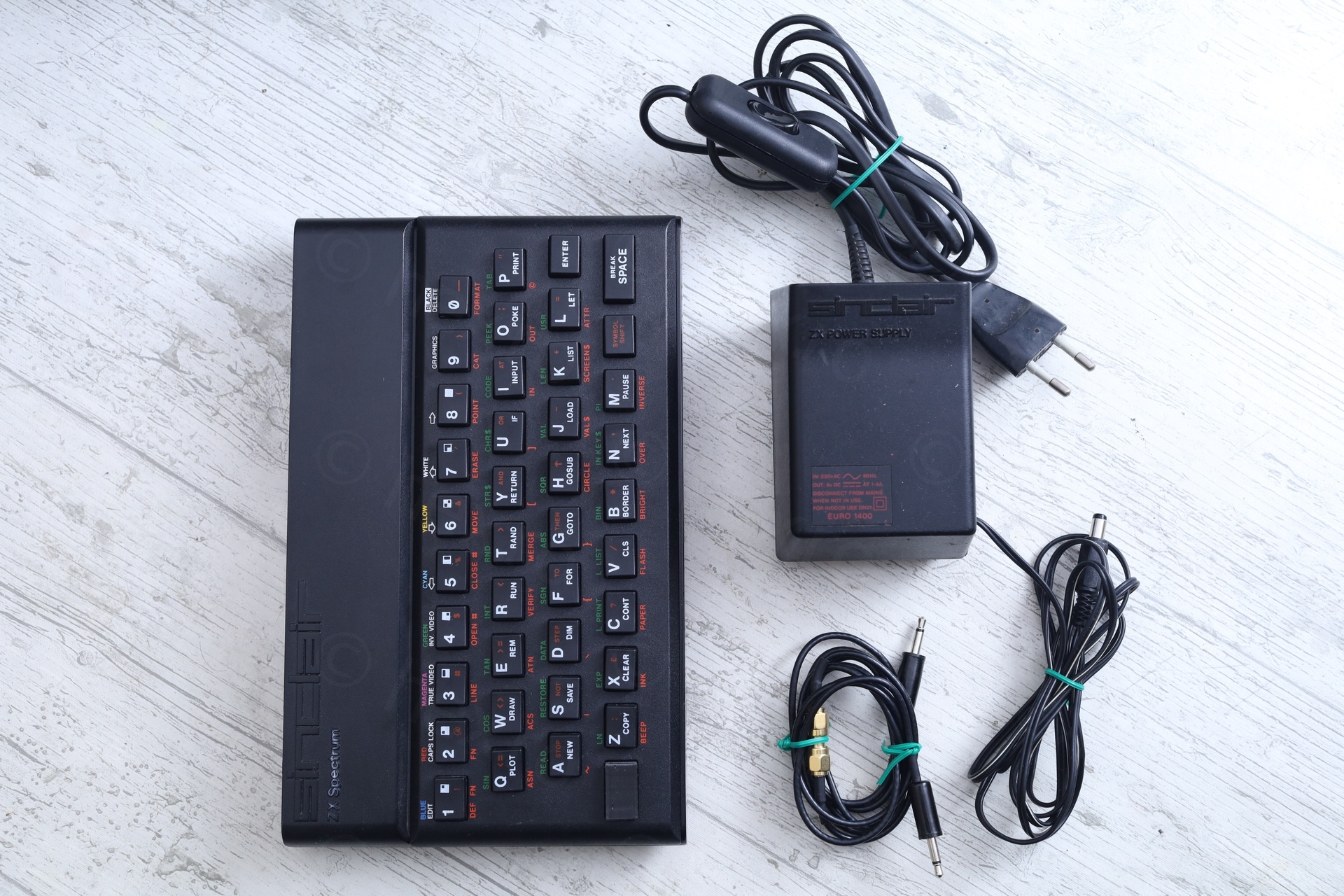
The computer was sold with the EURO 1400 power supply, and, except the keyboard missing a button, things looked … well … different:
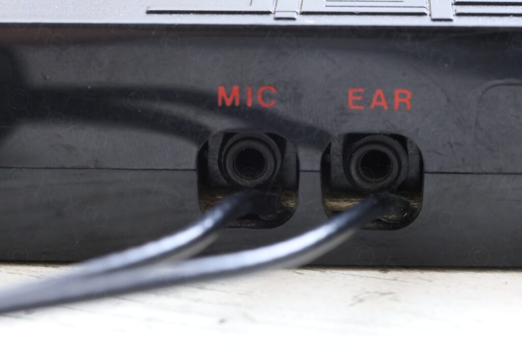
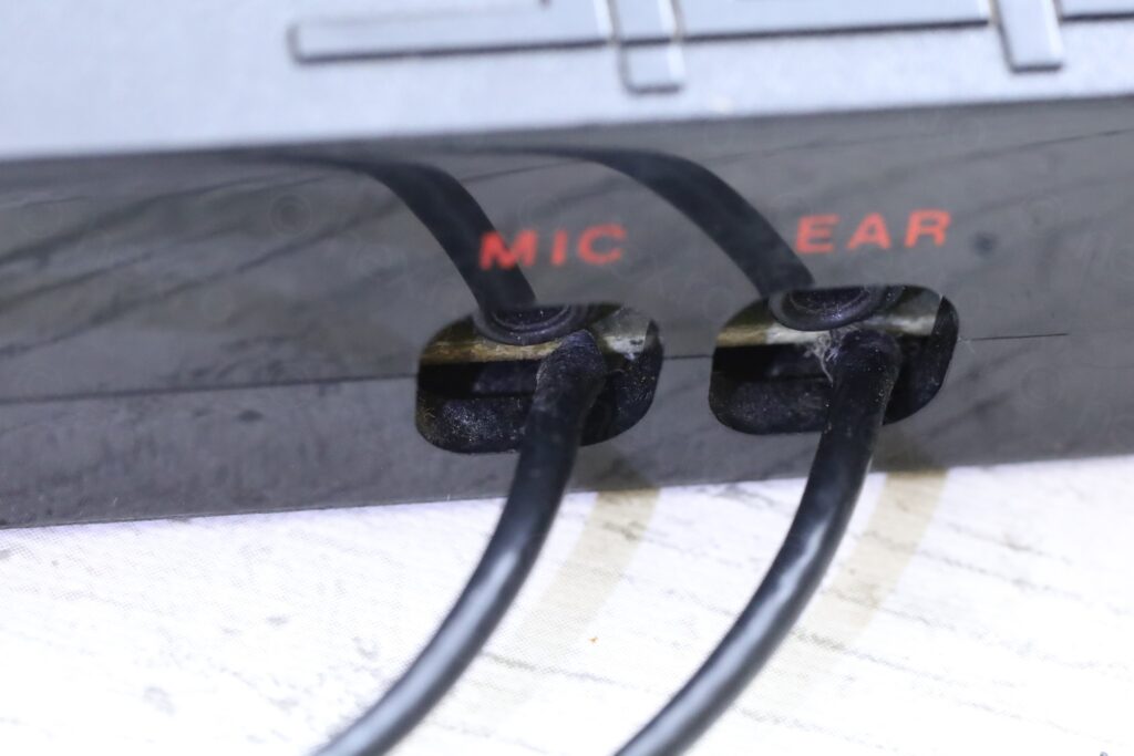
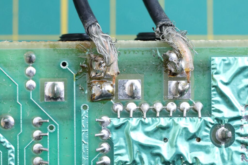
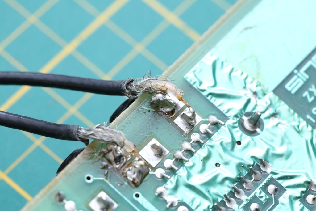
a) Audio cables soldered directly on the motherboard ?
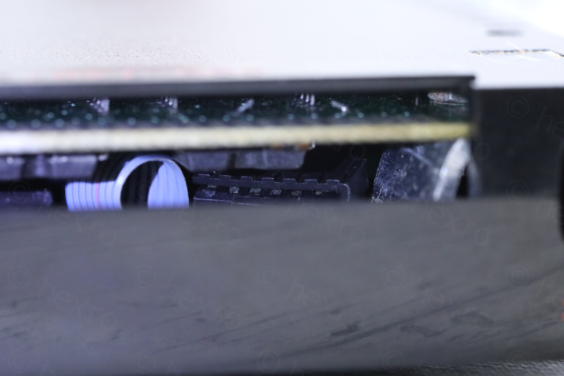
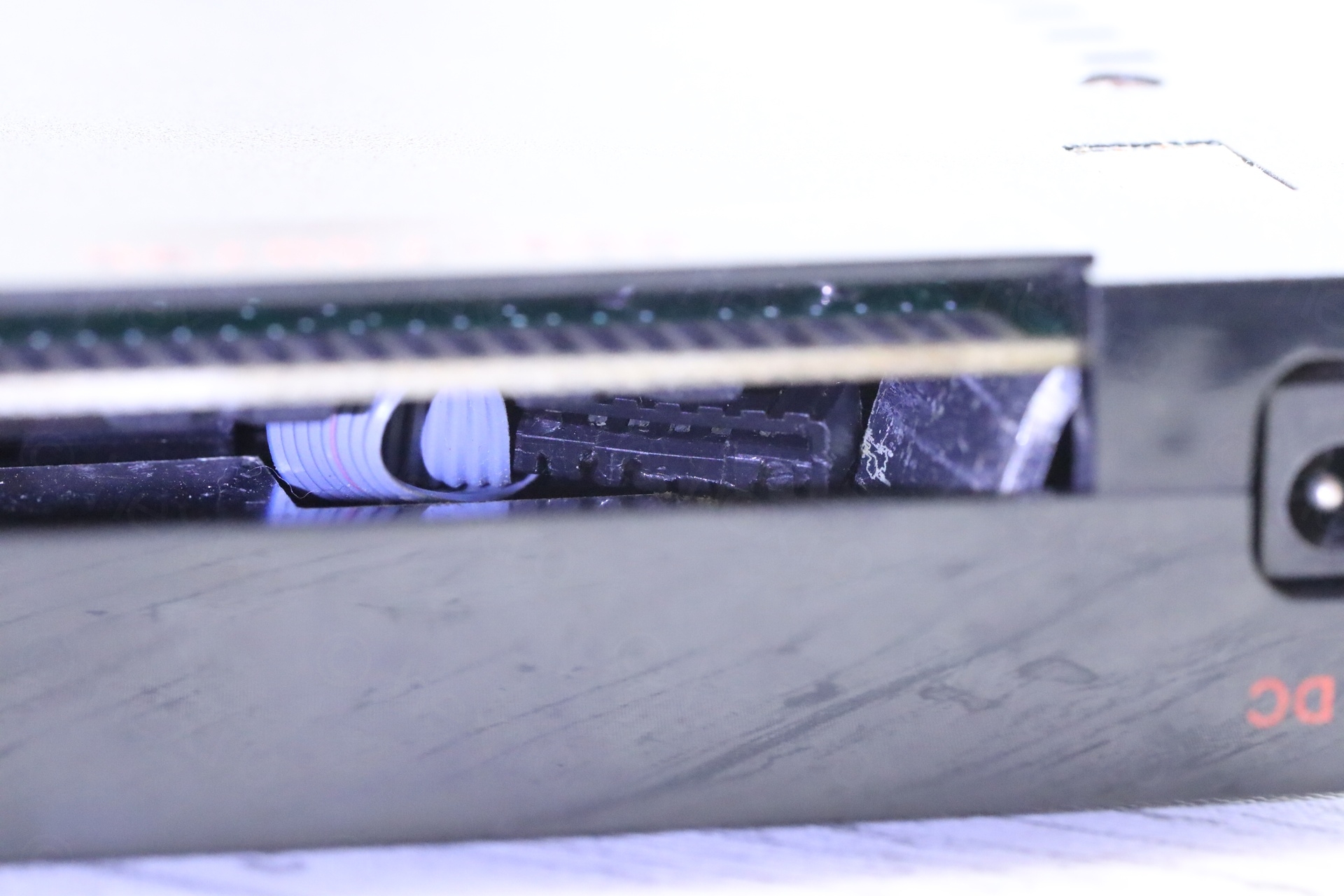
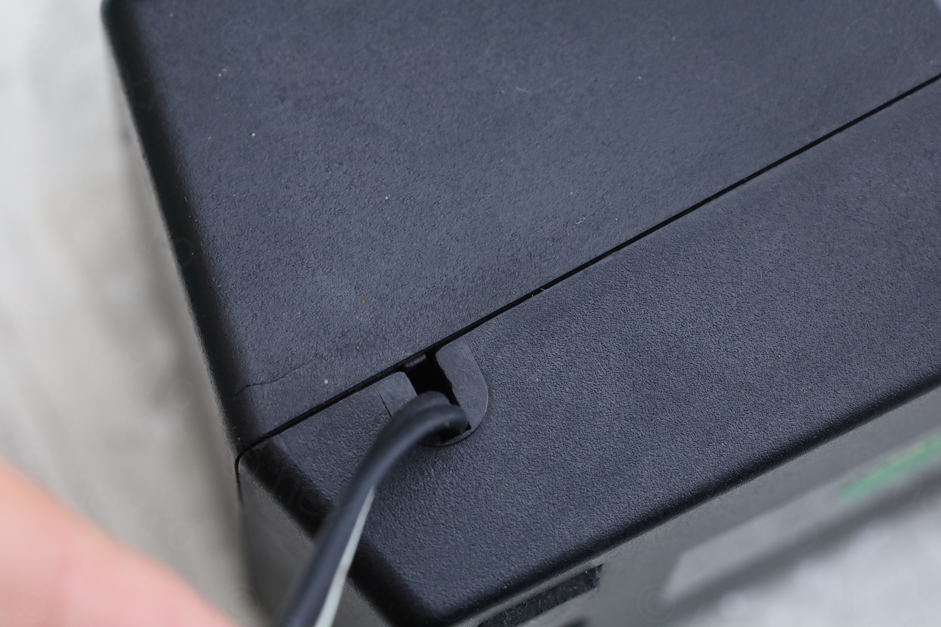
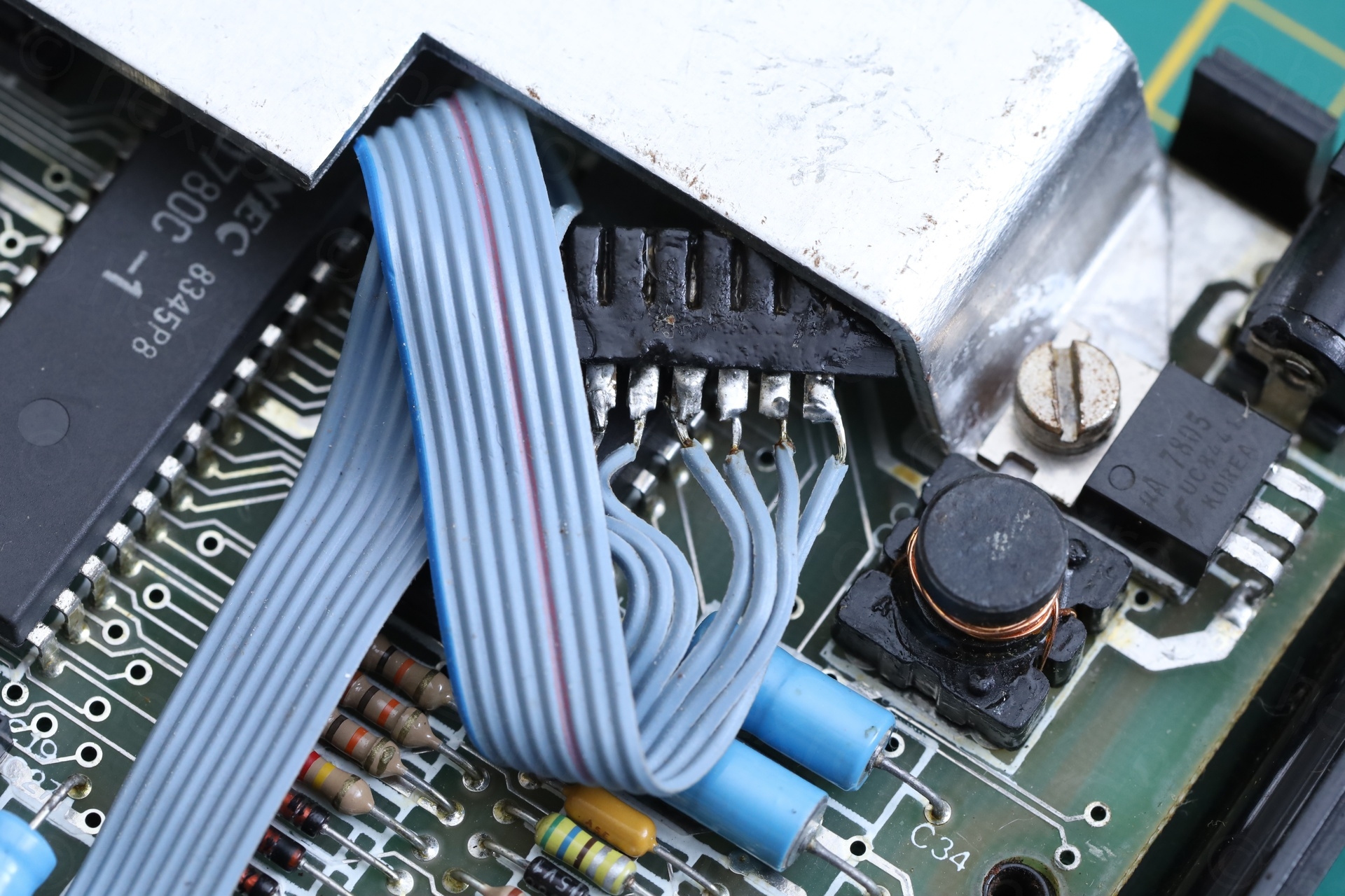
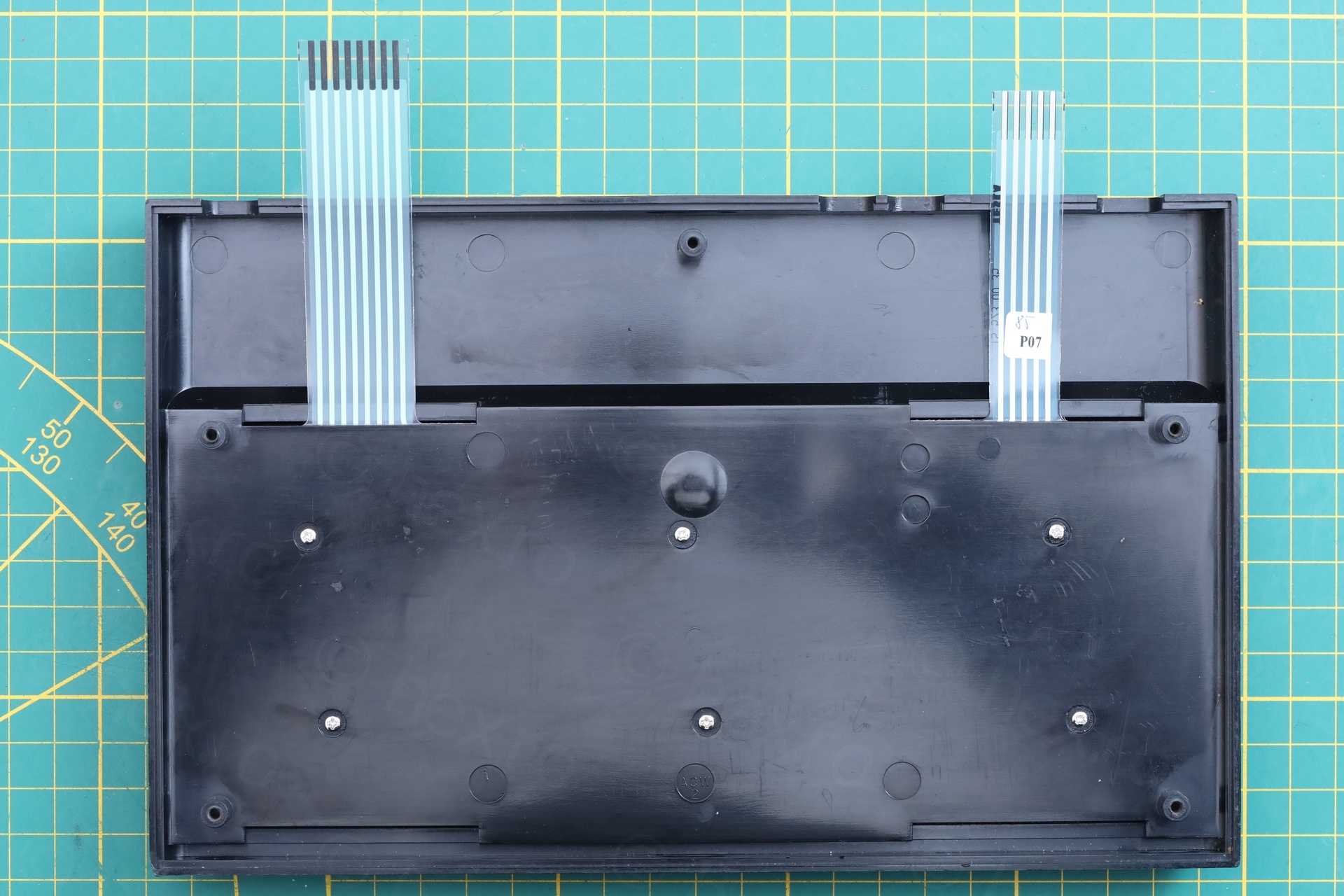
b) looking through the extension slot, I could see grey flat ribbon cables sandwiched inside:
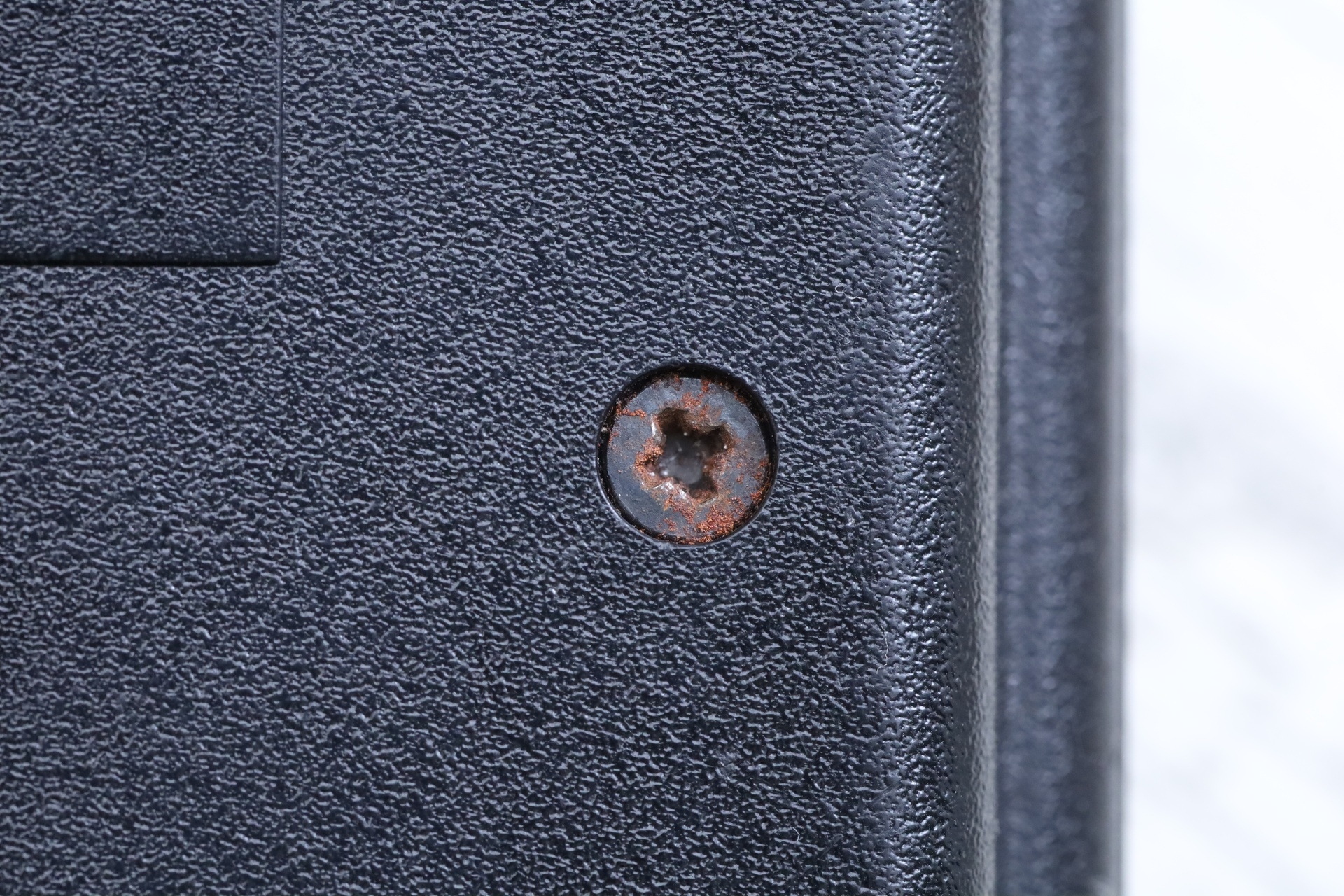
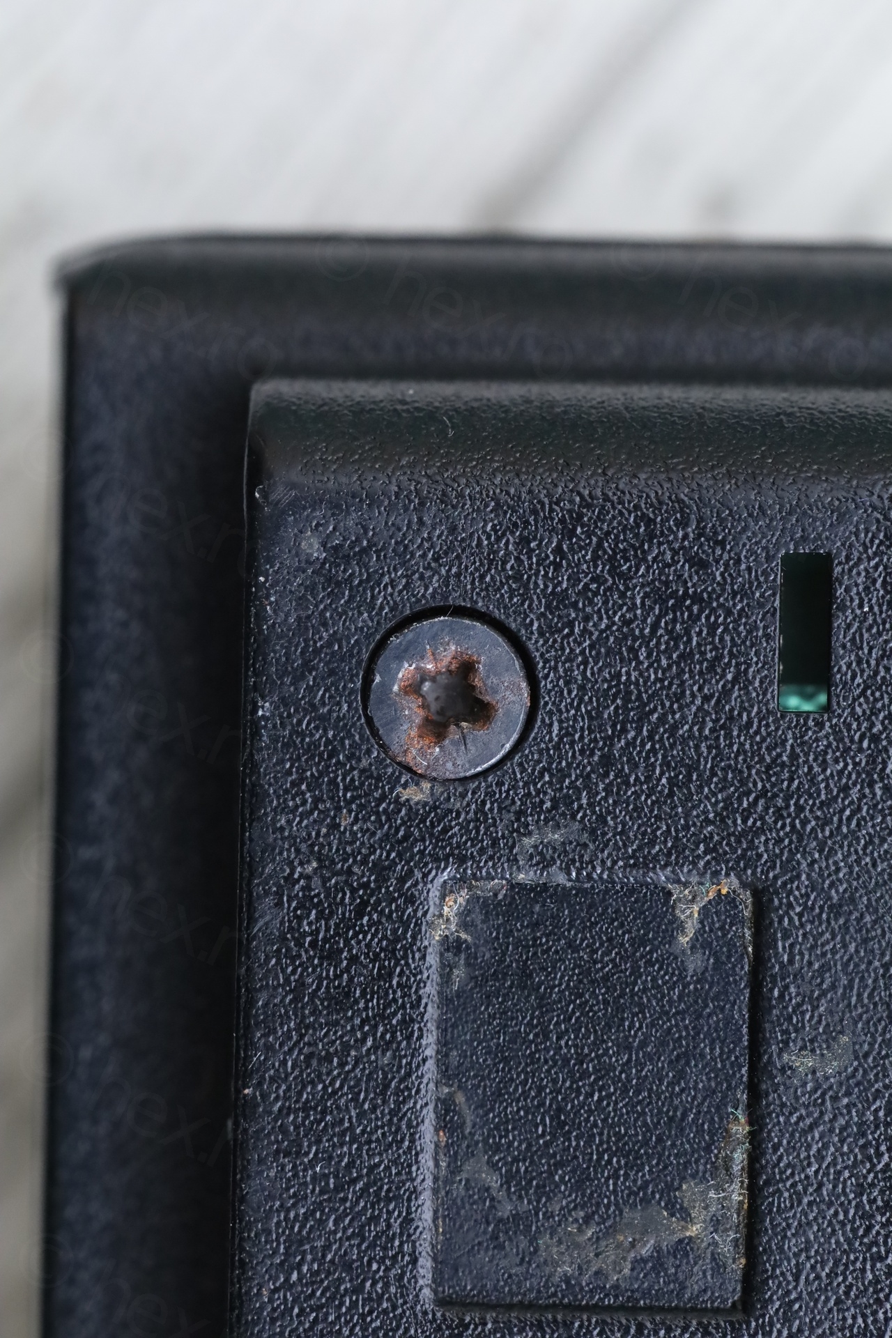
c) rust on TV antenna / screws:
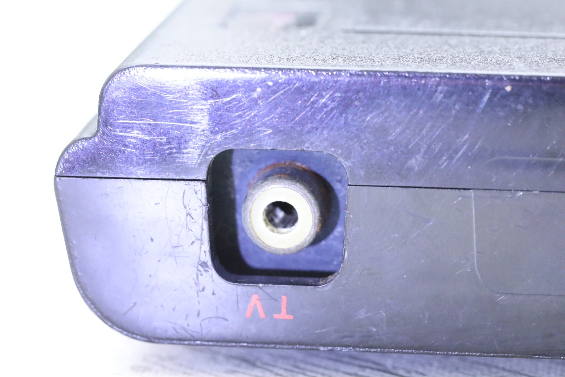
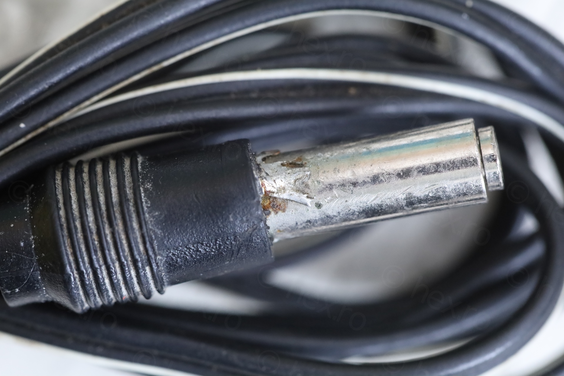
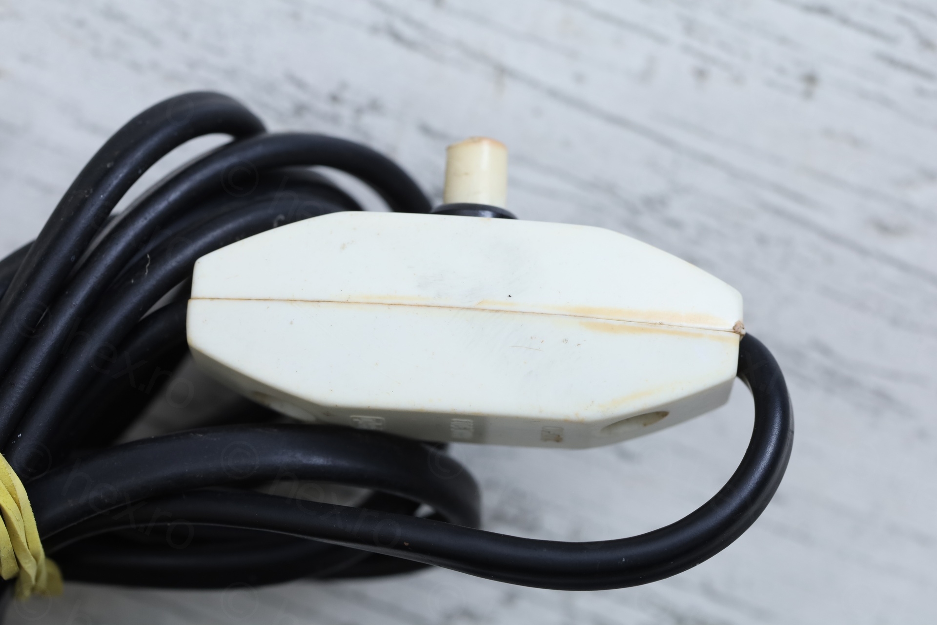
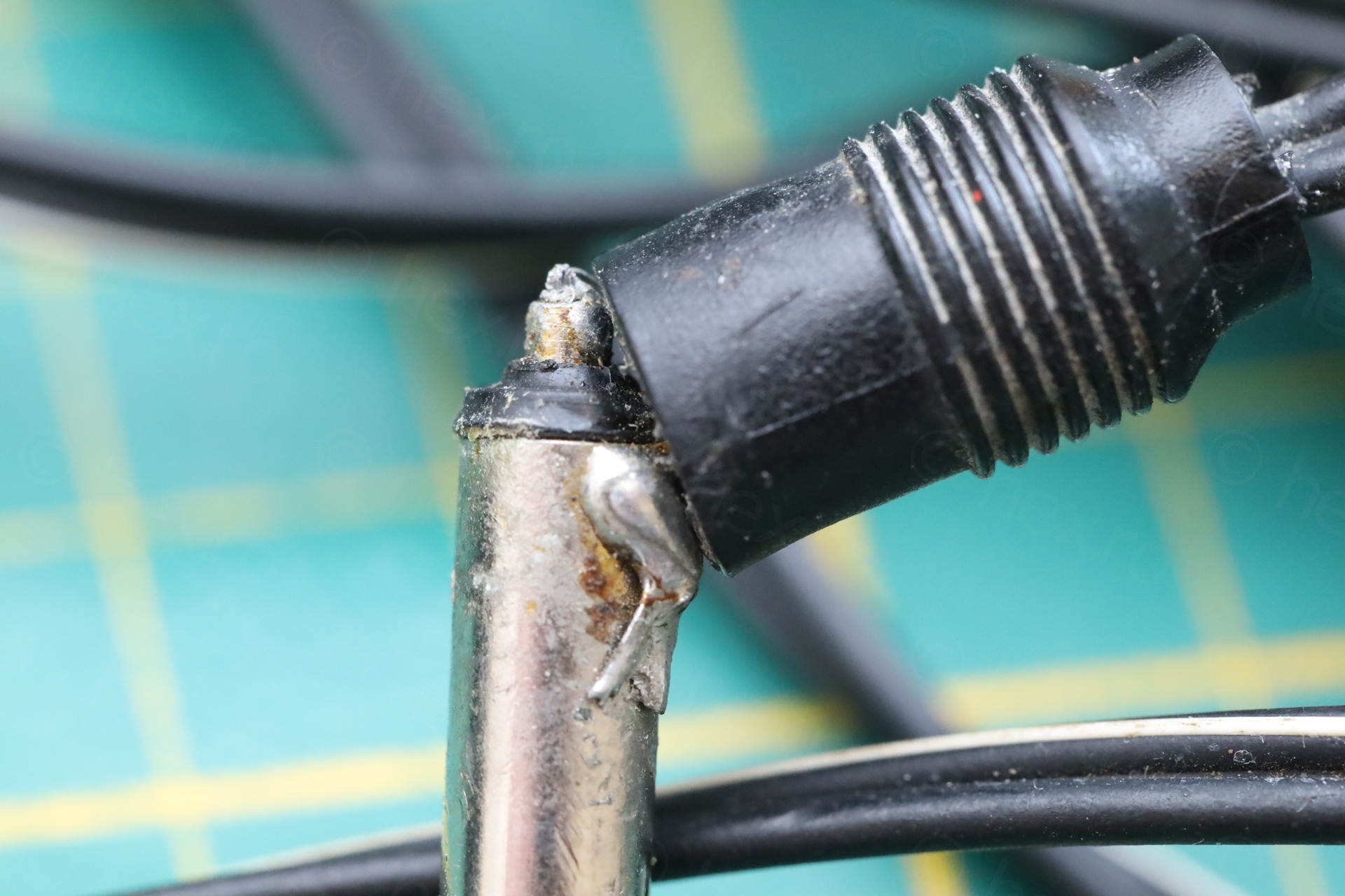
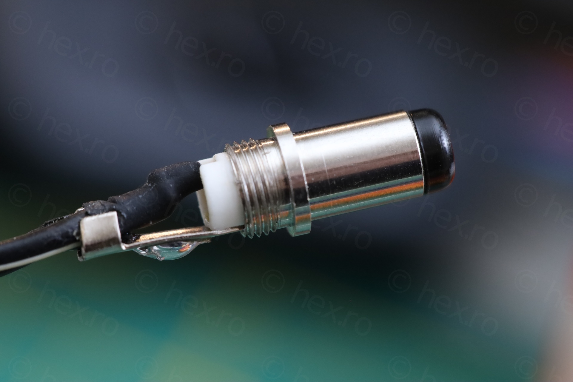
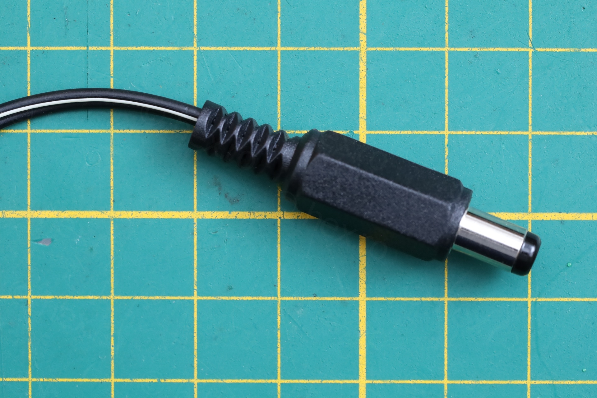
d) aftermarket inline ON/OFF switch for the power supply, different low voltage cable (without the strain relief) and visible soldering on the DC jack:
It was time to have a look inside.
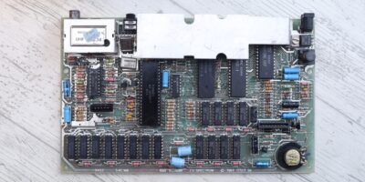
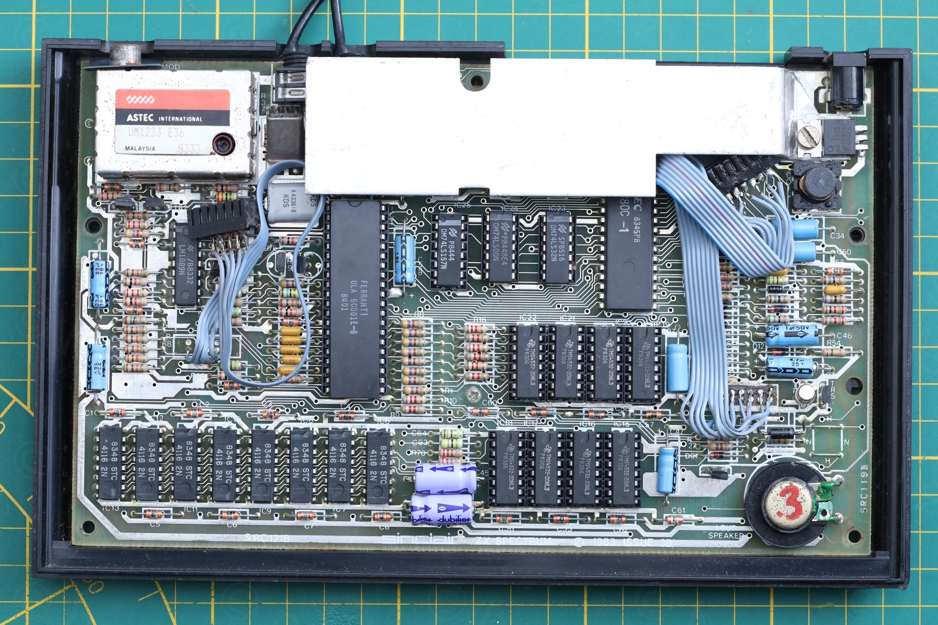
Visual Inspection (Inside)
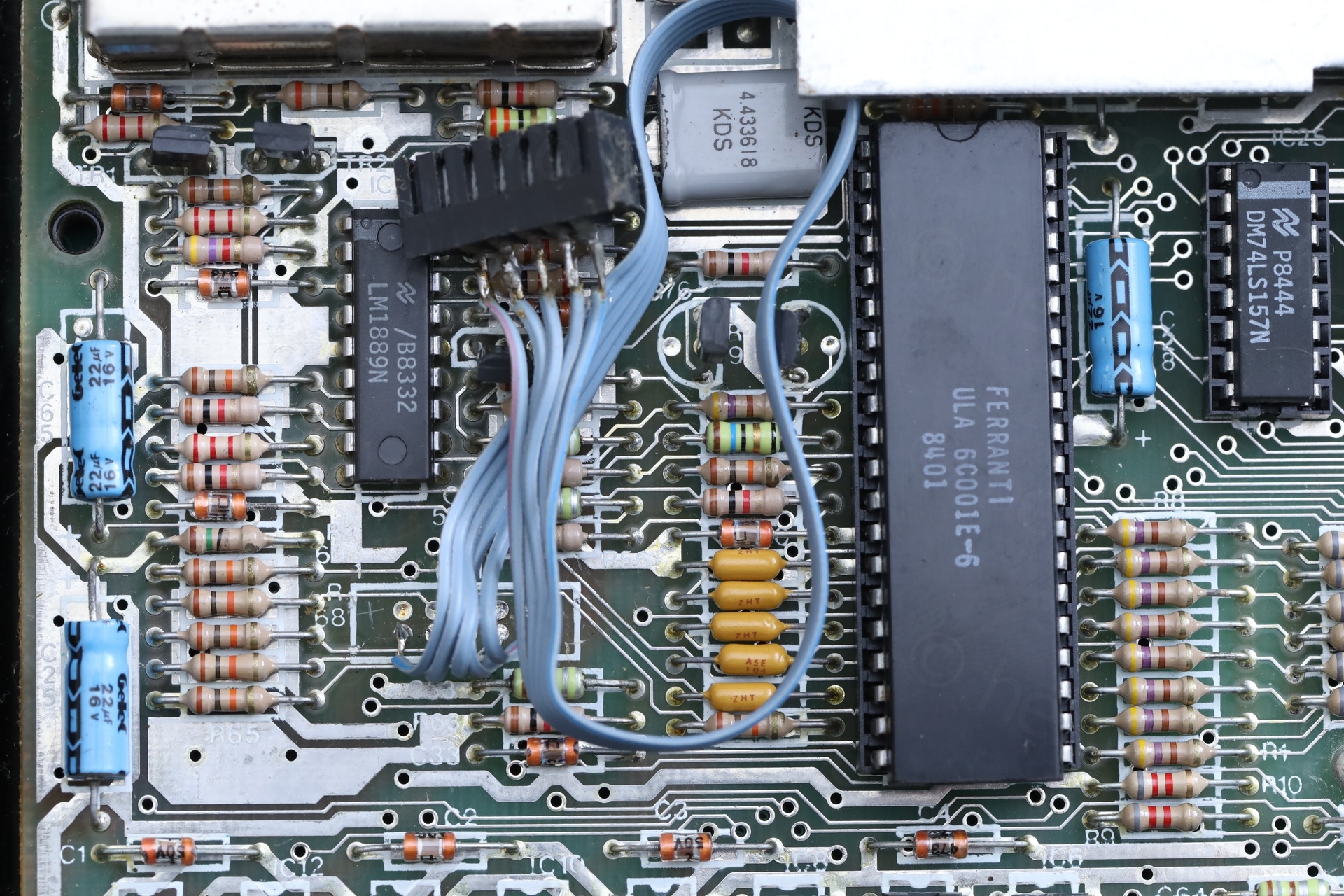
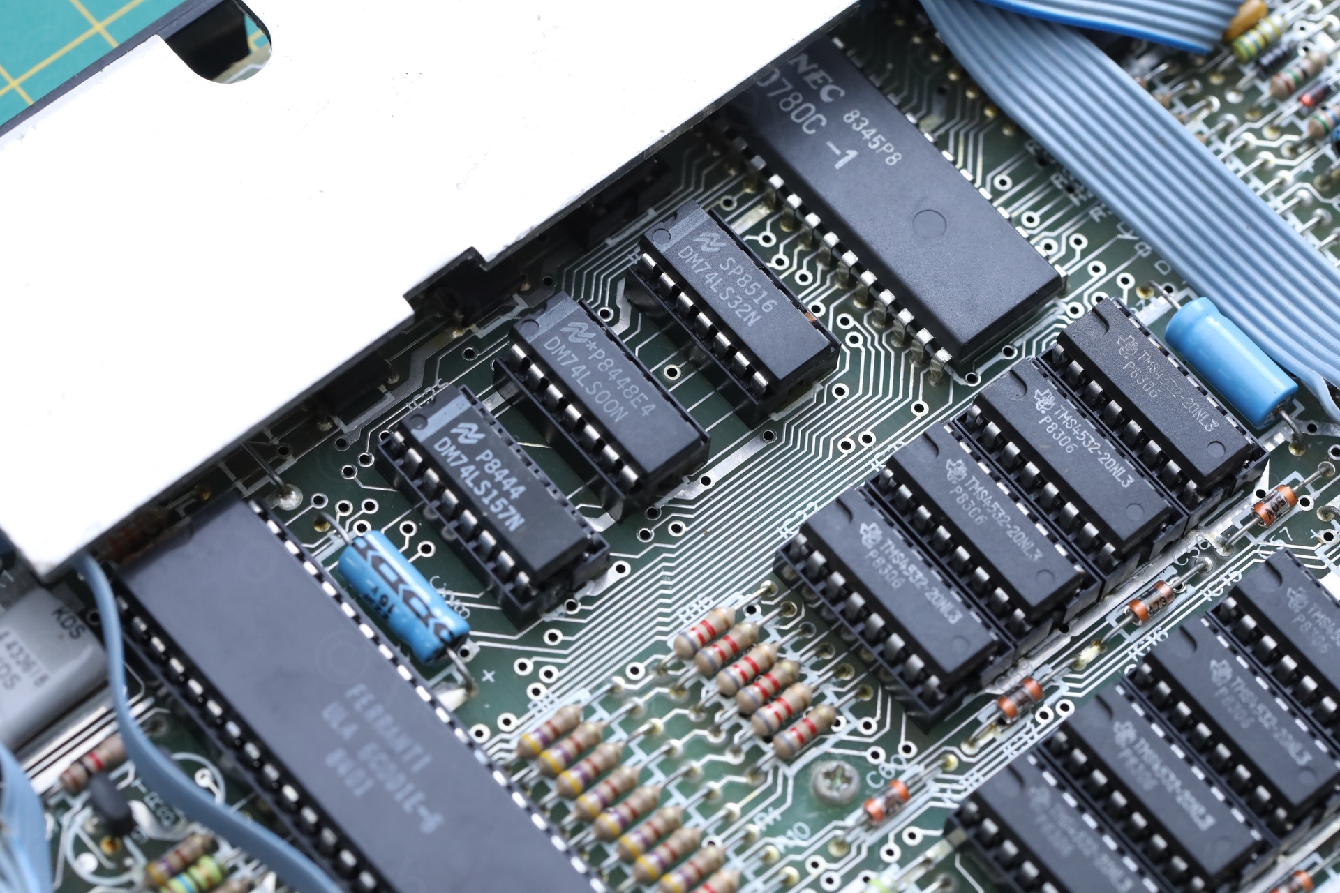
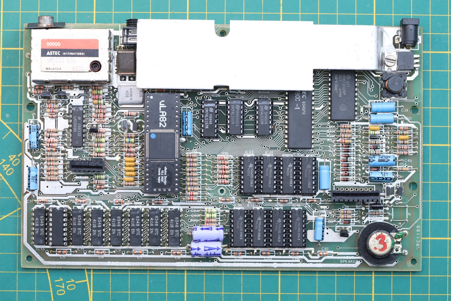
The first view inside got me wondering even more:
Why would the computer need extension wires for the keyboard connectors ? Was it used with a different keyboard than the one installed ? Was this plastic keyboard so poor quality that the owner had to use an external keyboard ?
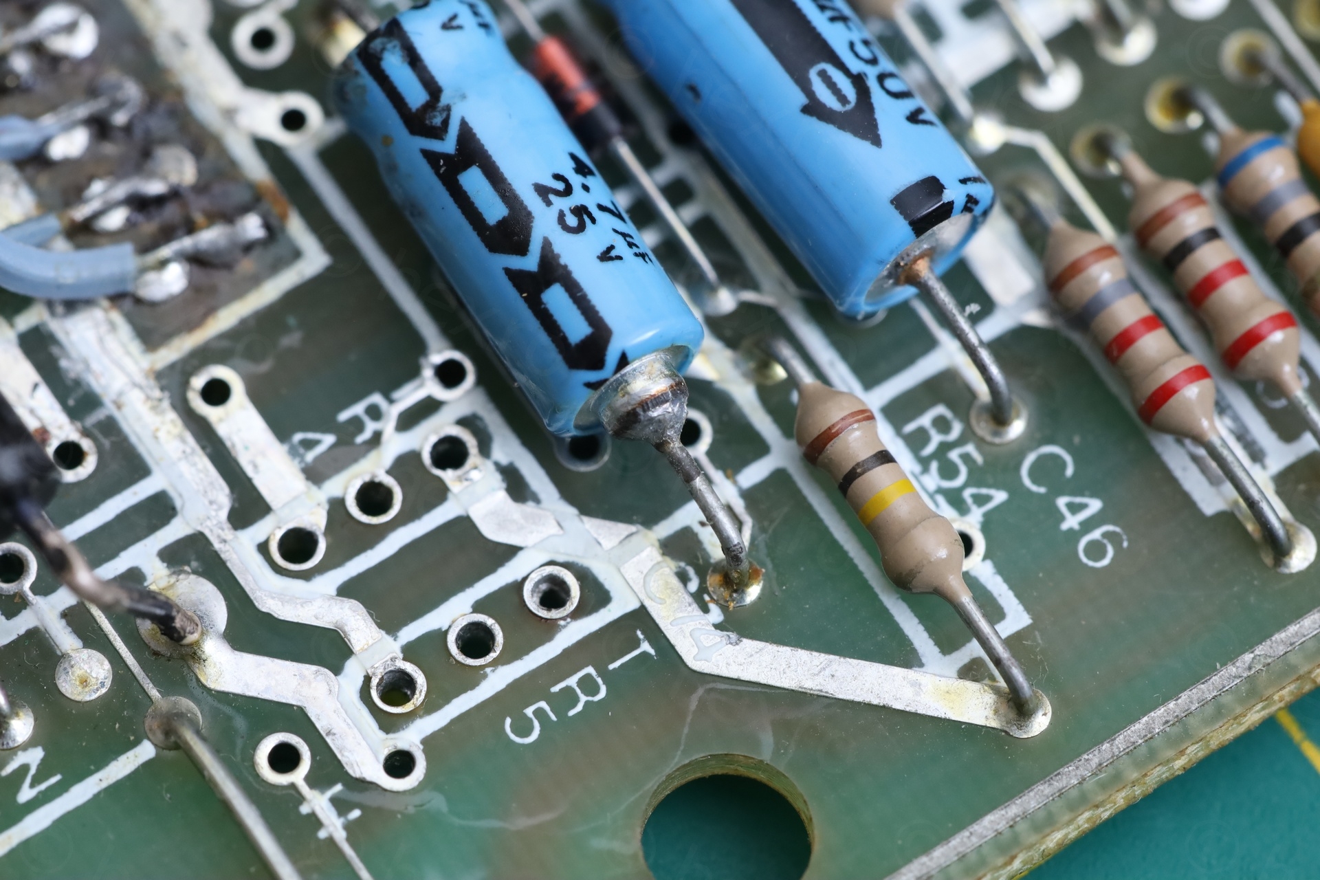
I also spotted a replacement transistor in the DC-DC power supply. But too many things to photograph first!
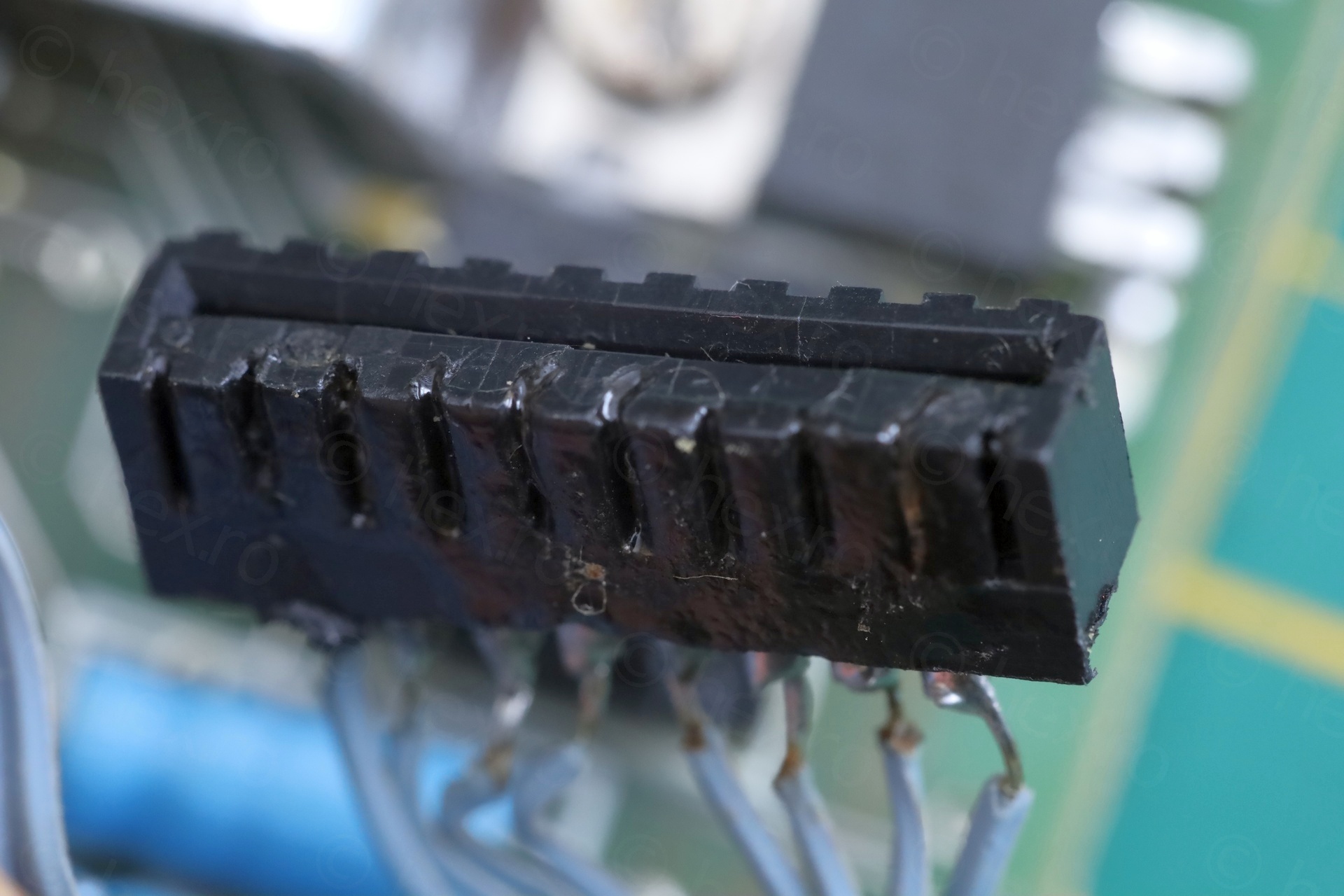
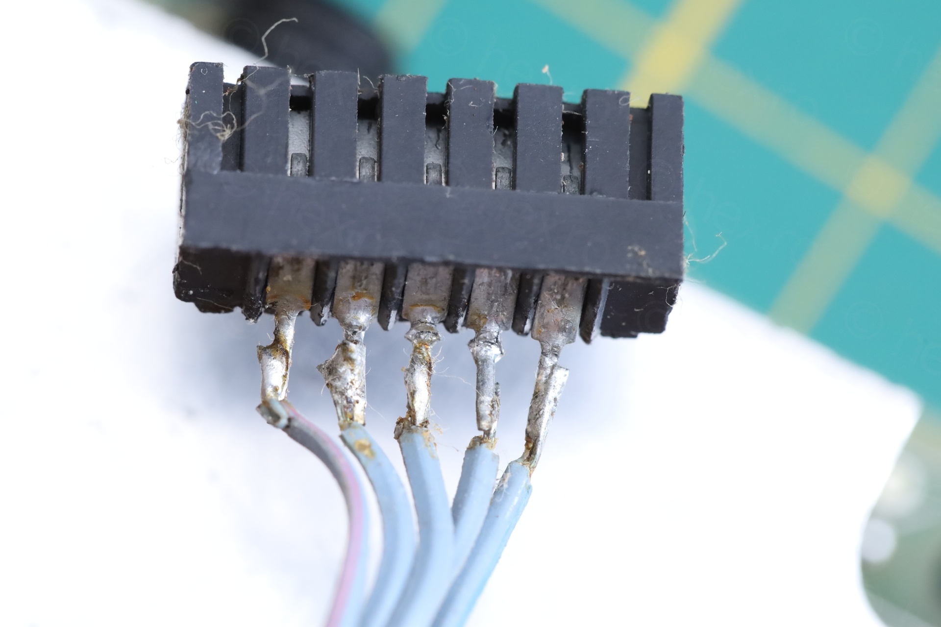
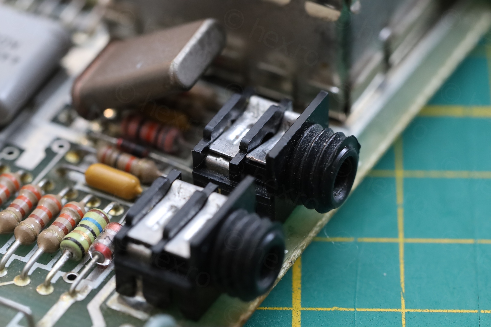
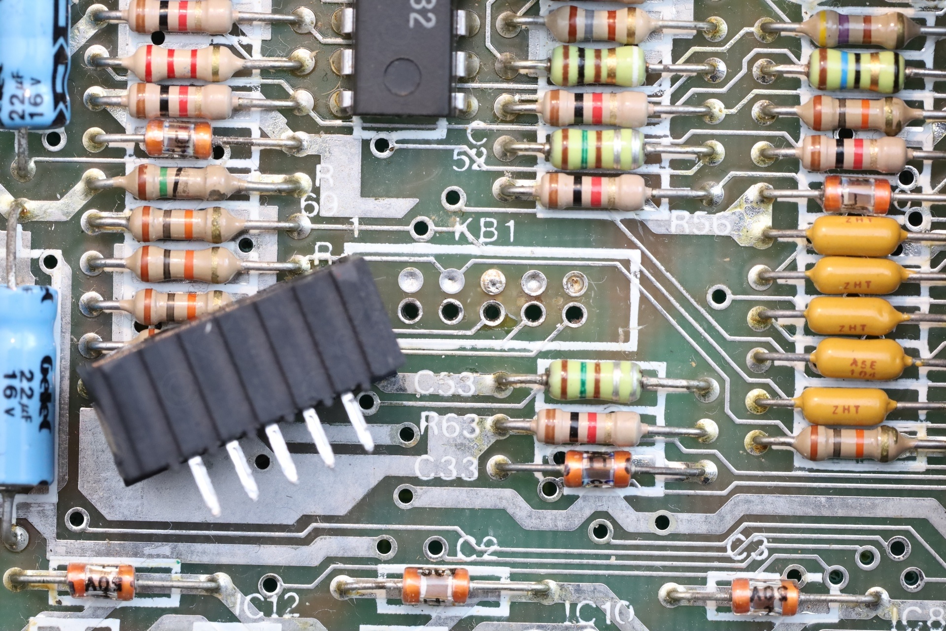
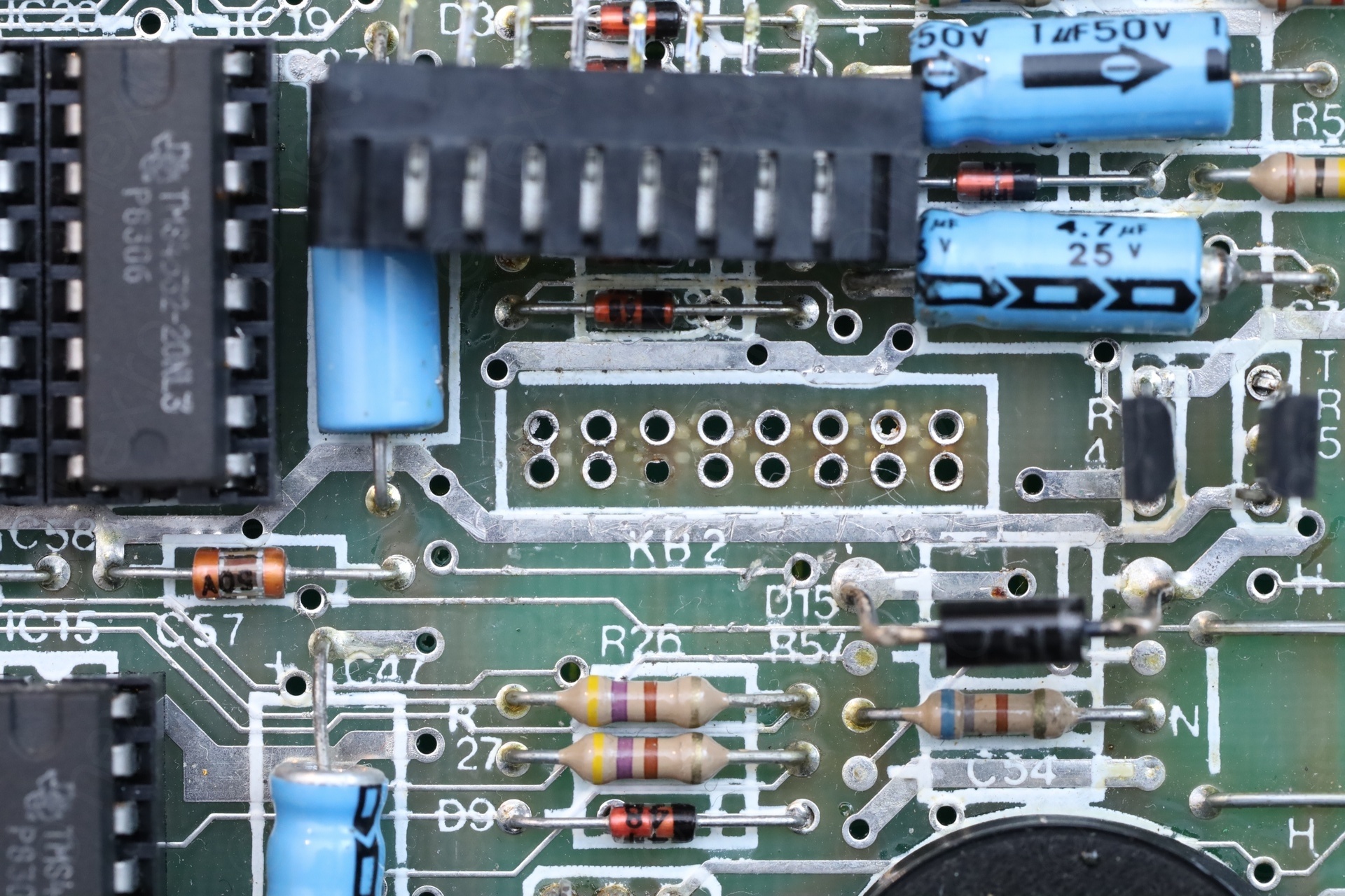
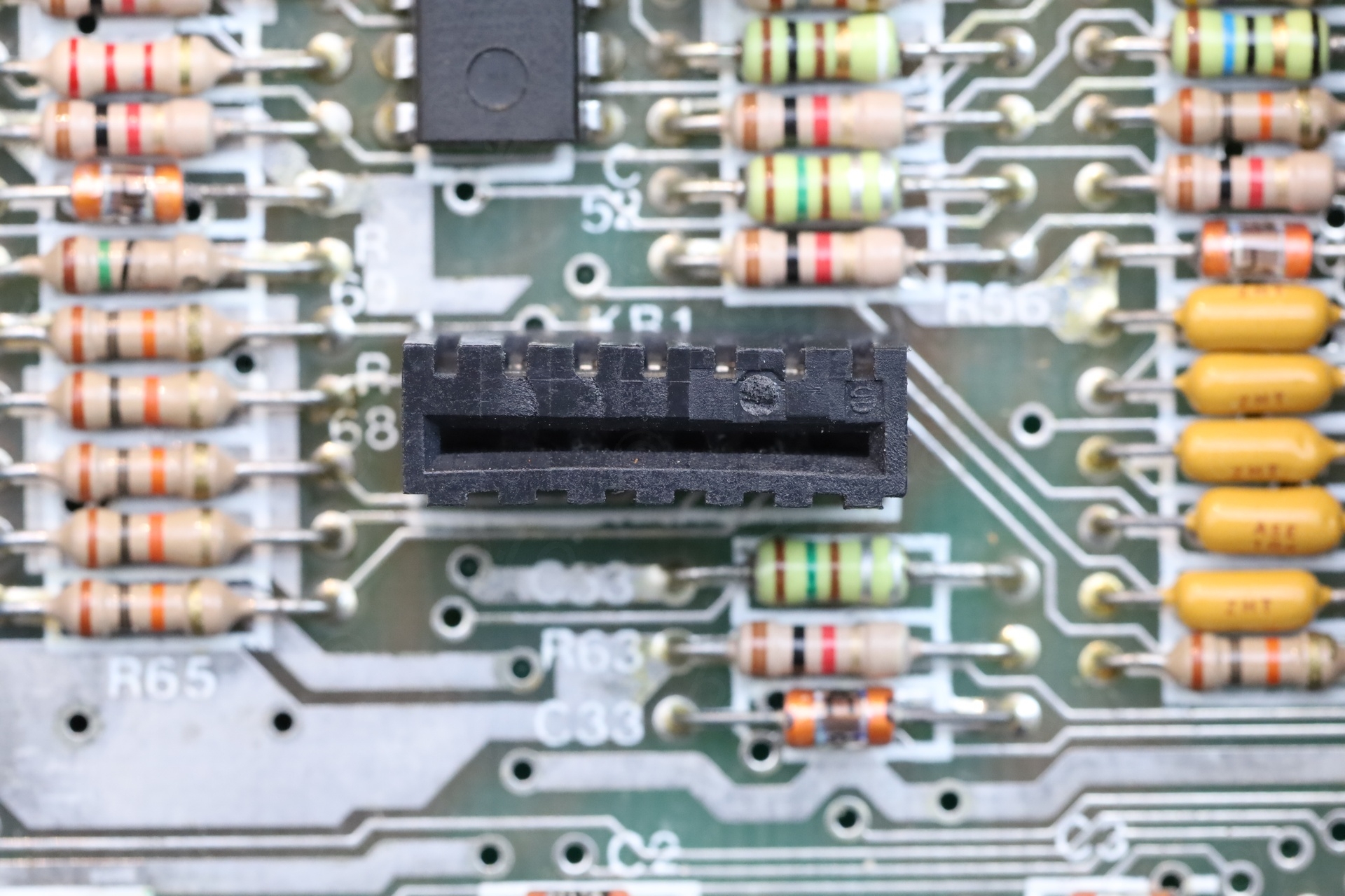
a) the right keyboard connector was de-soldered, to be reattached to the end of the flat ribbon cable. Copious amount of glue found on the connector itself:
Sane treatment applied to the left keyboard connector (minus the glue):
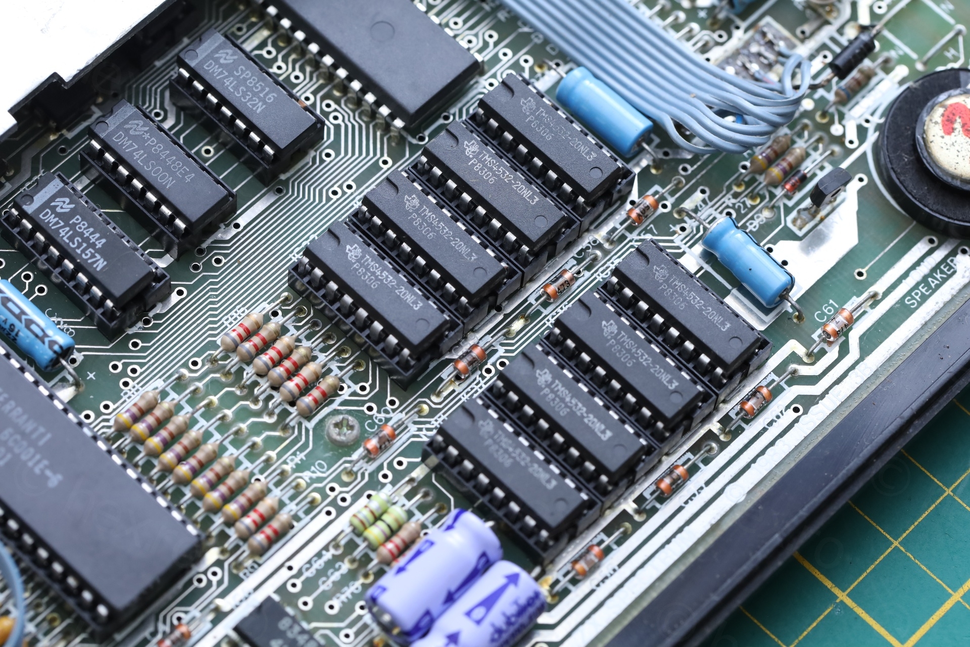
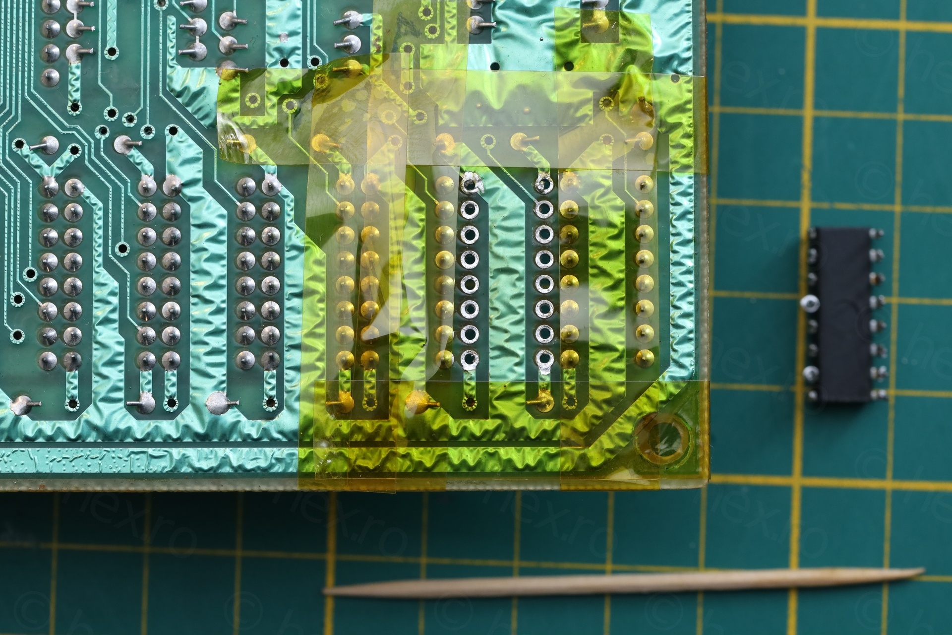
b) The Upper RAM ICs and their logic were installed in sockets. Was this an 16Kb Spectrum upgraded to 48k ?
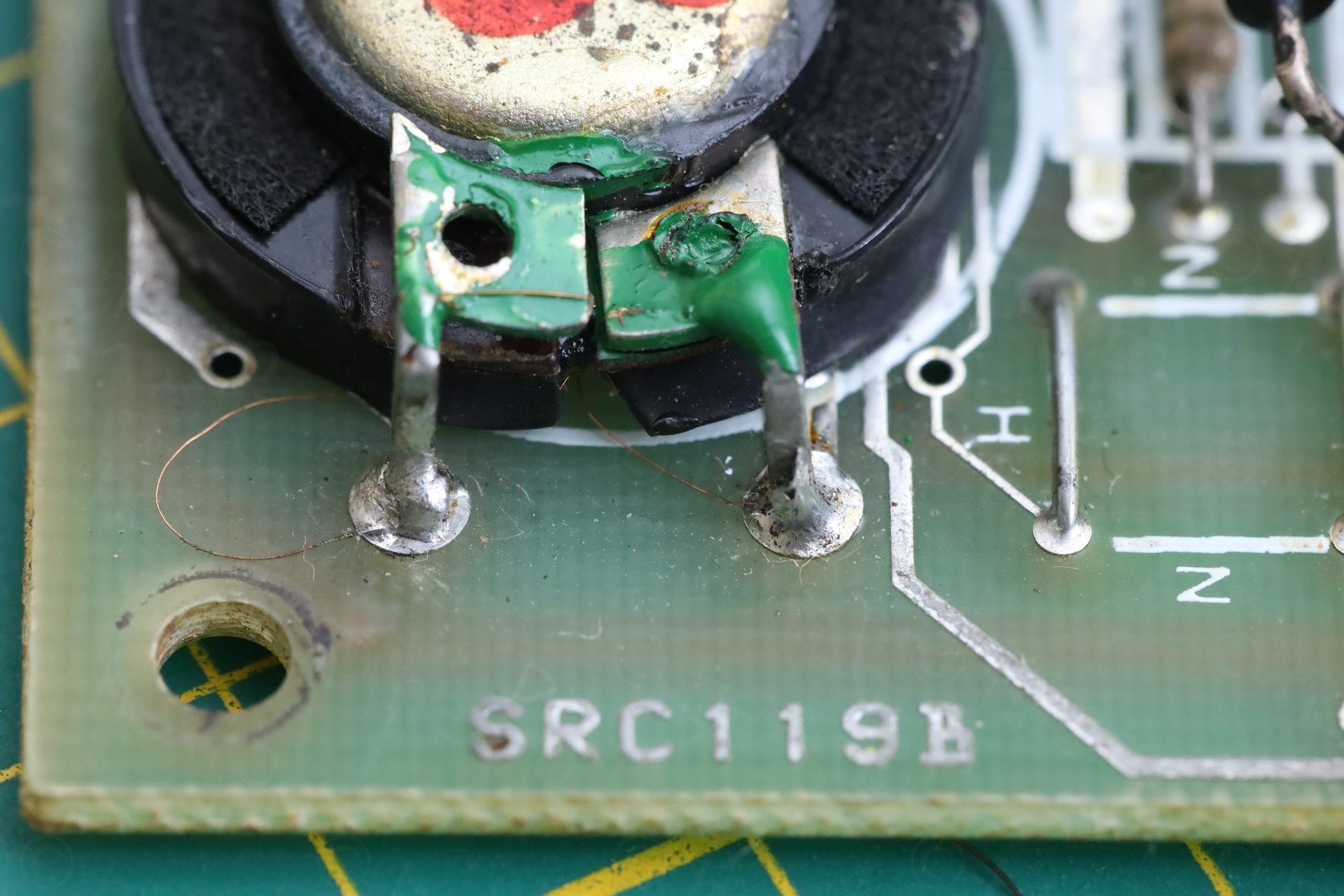
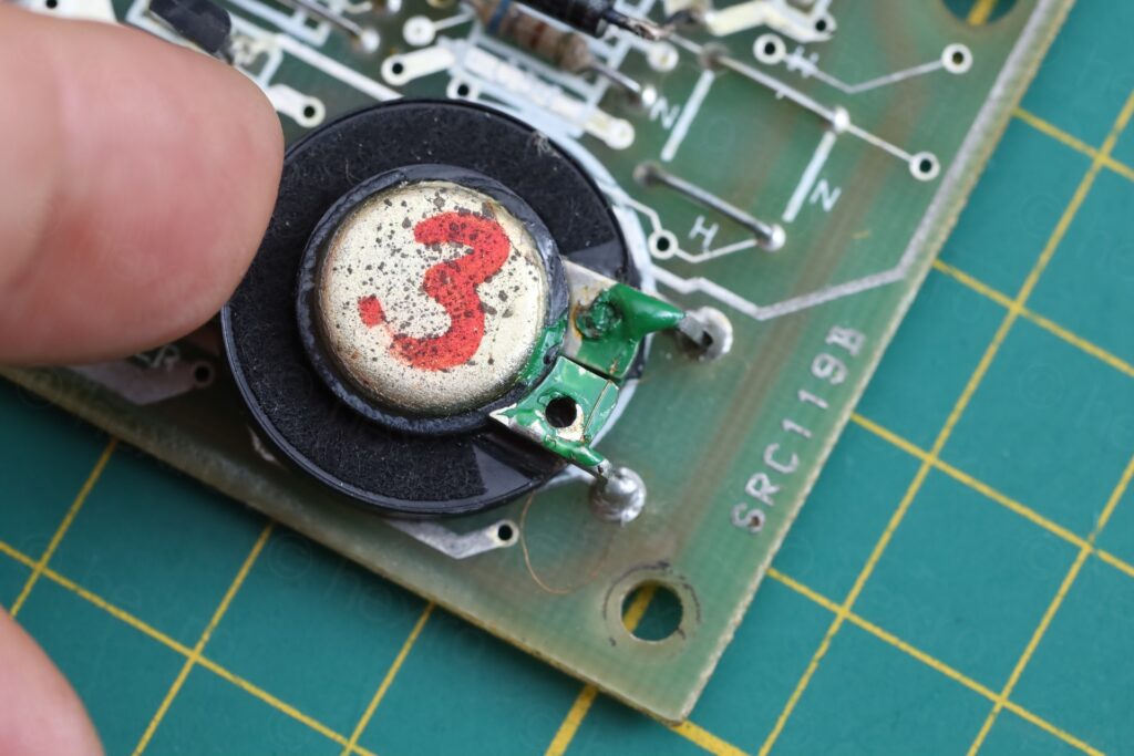
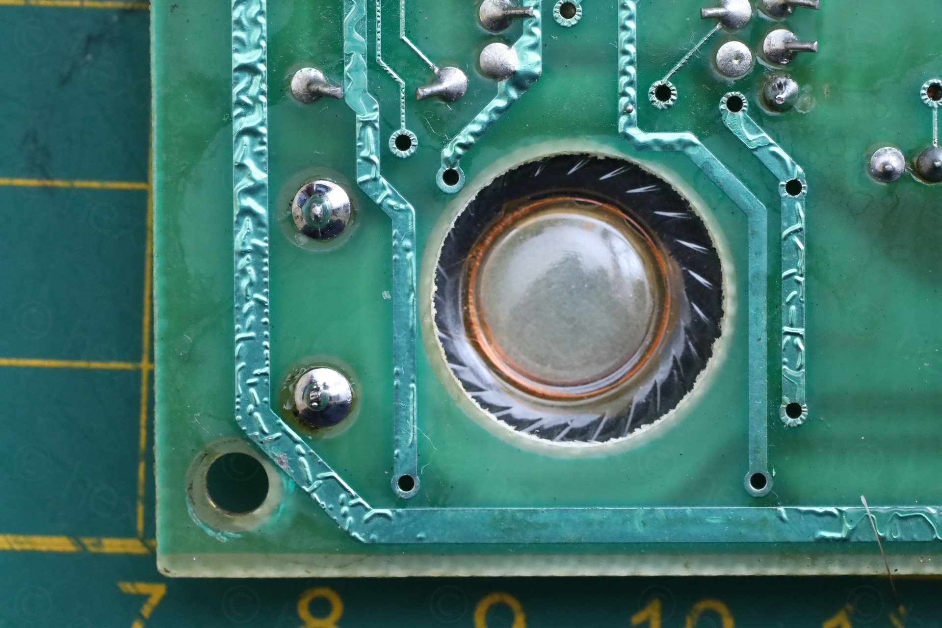
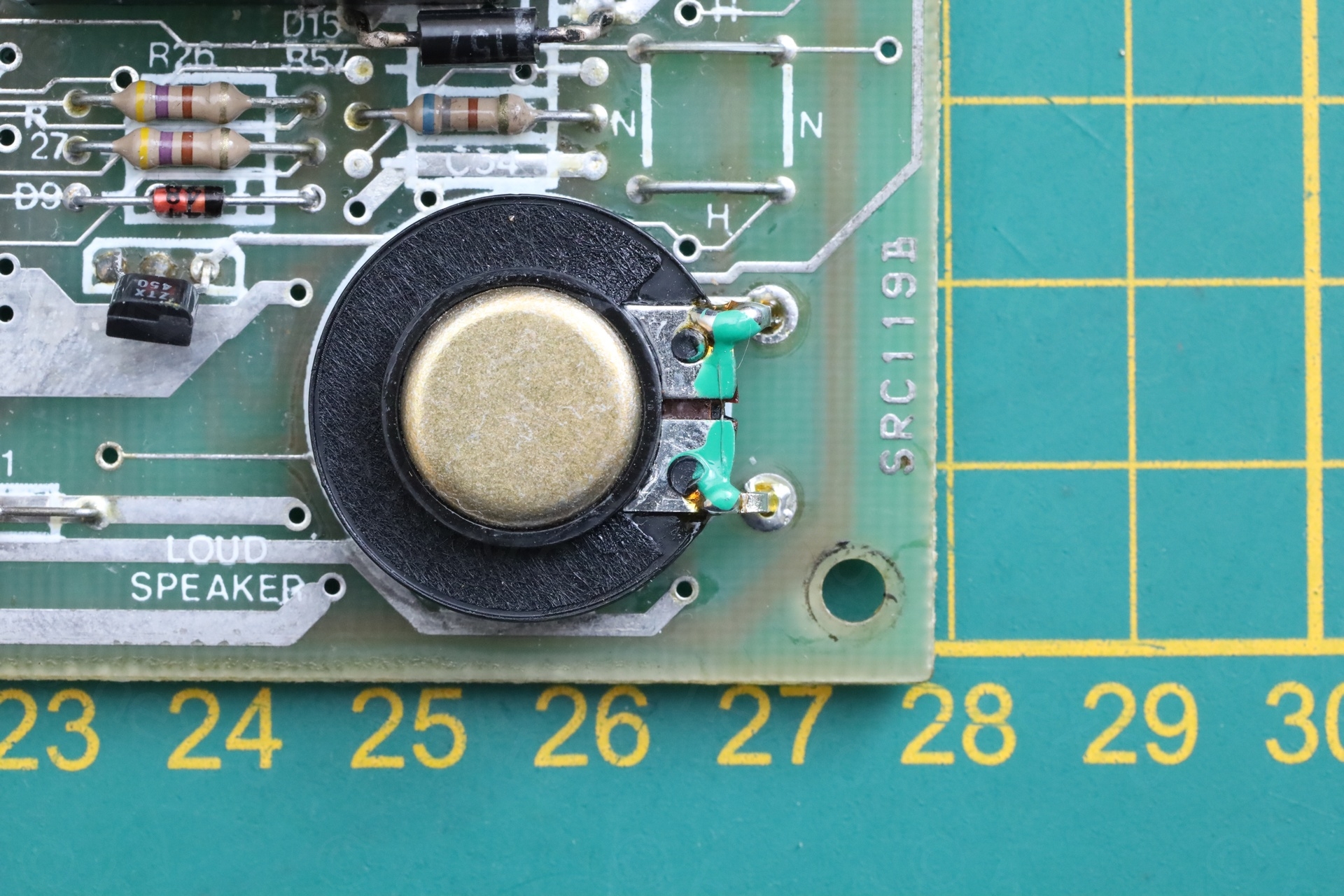
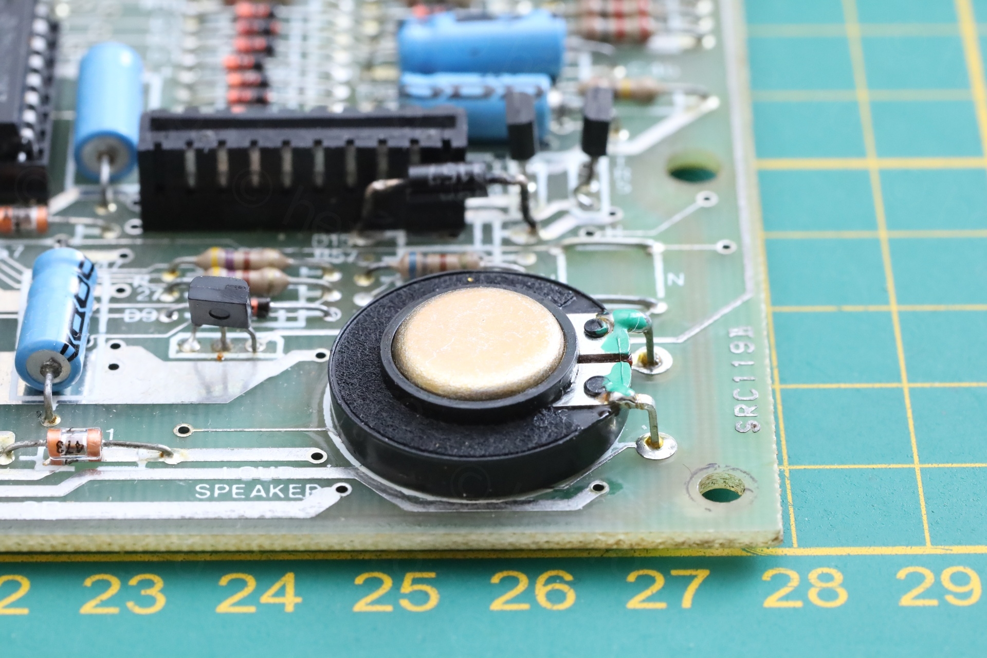
c) Speaker snapped from its support legs (flapping around); thin wires were visible. Somebody fished out the wires and had them re-soldered:
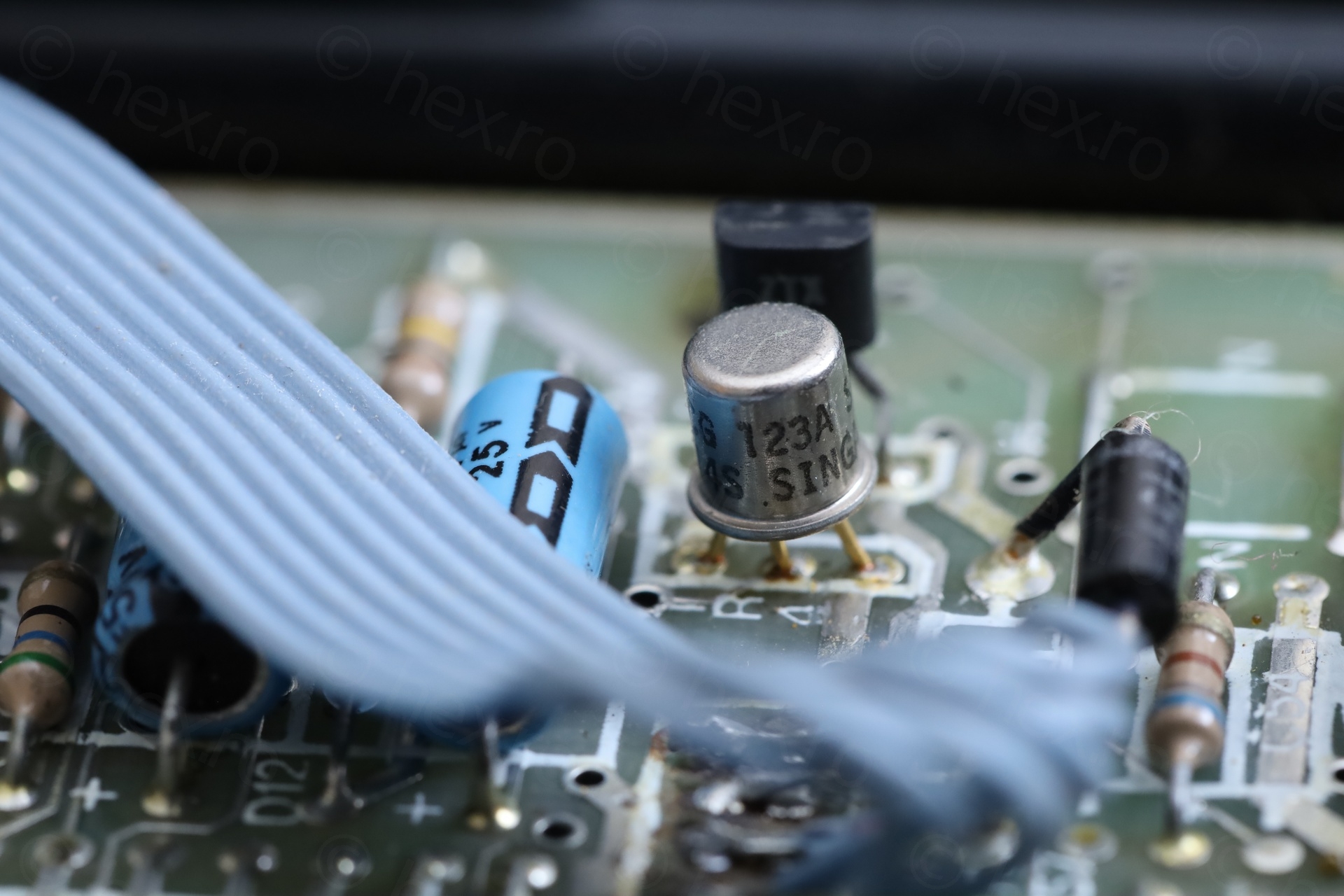
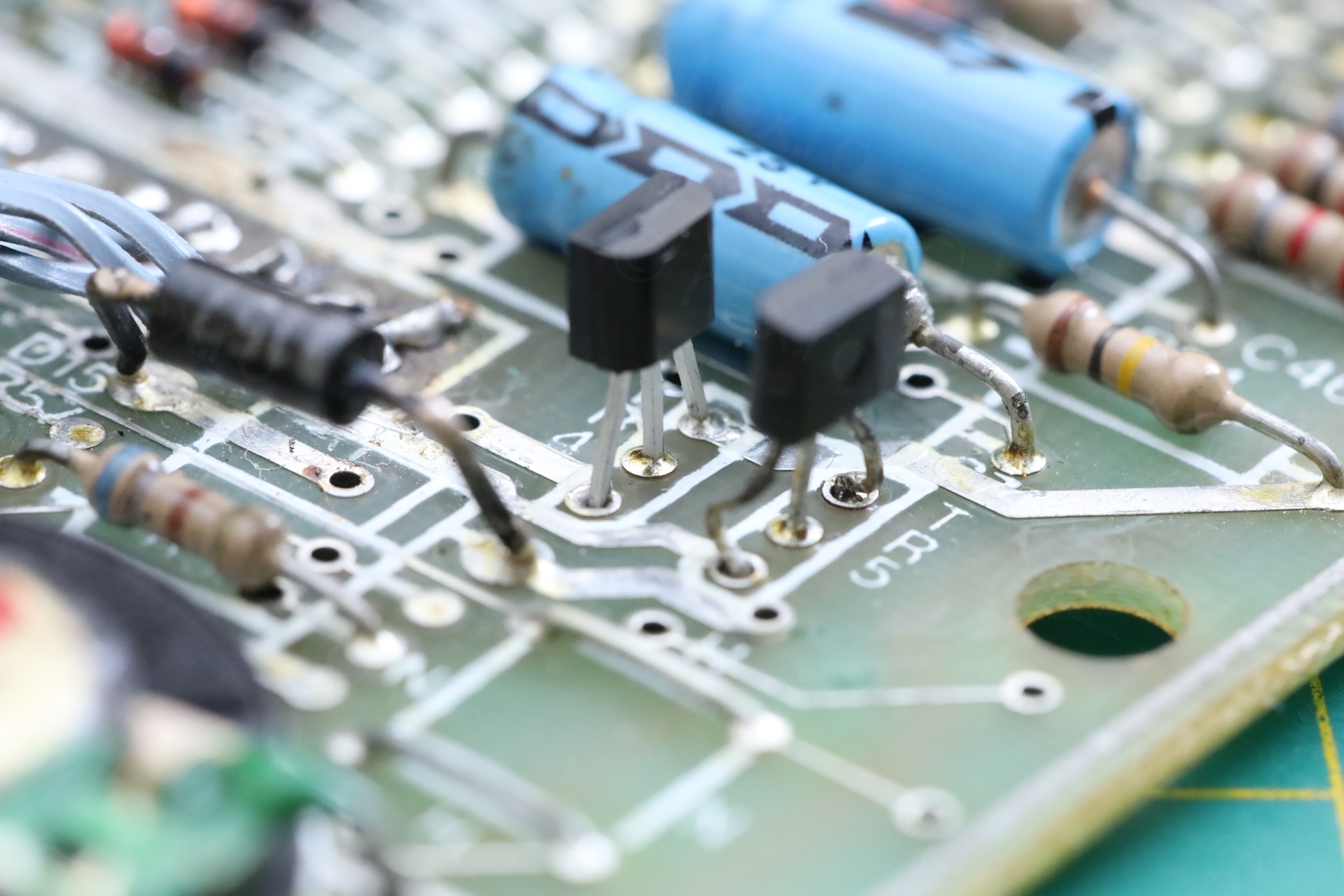
d) TR4 transistor was replaced with ECG 123A transistor (not suitable):
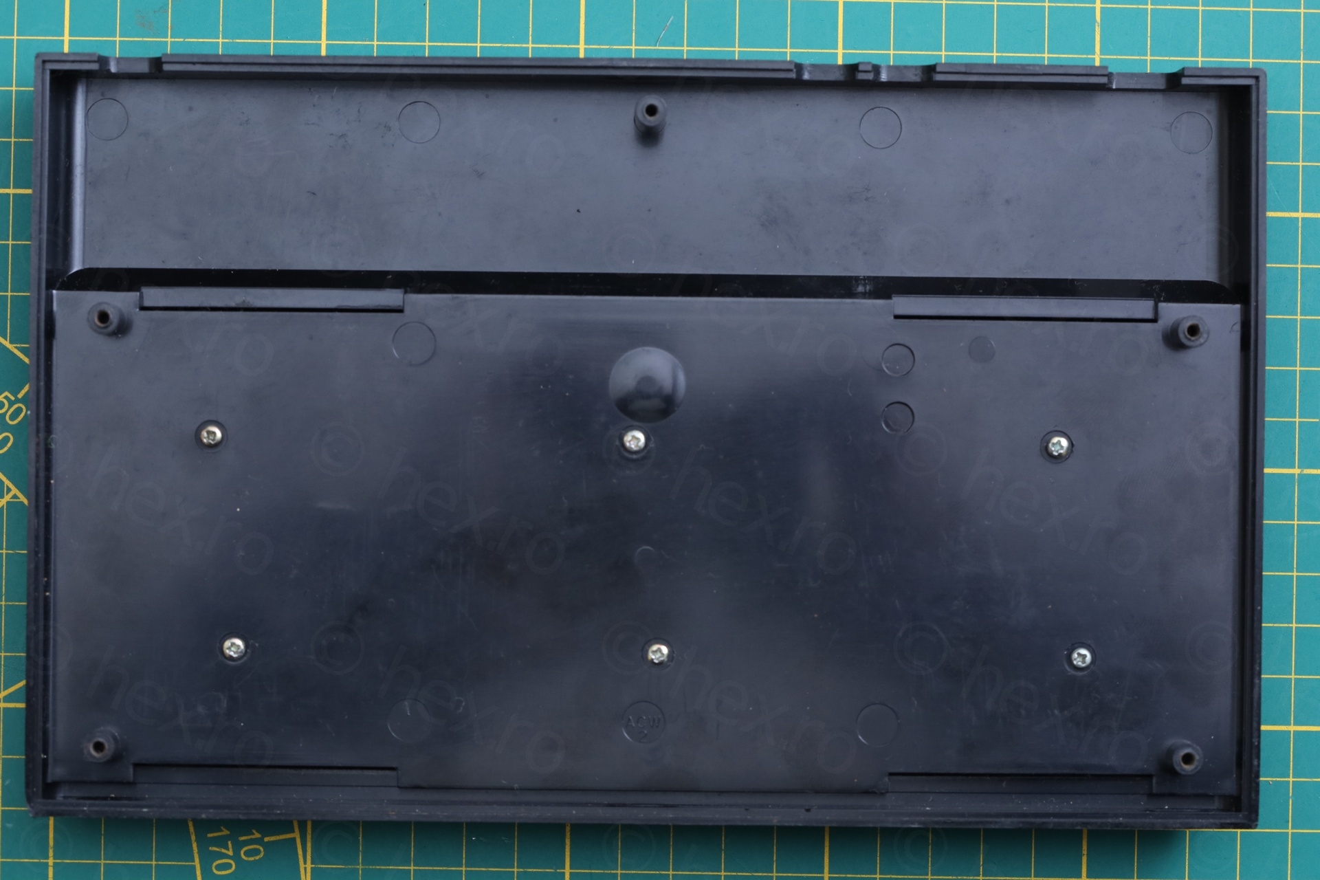
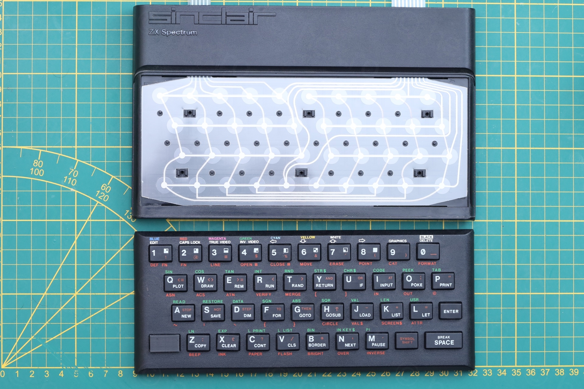
e) The 6 screws that were supposed to keep the plastic keyboard attached to the case were all loose. The membrane was missing:
Power ON Tests
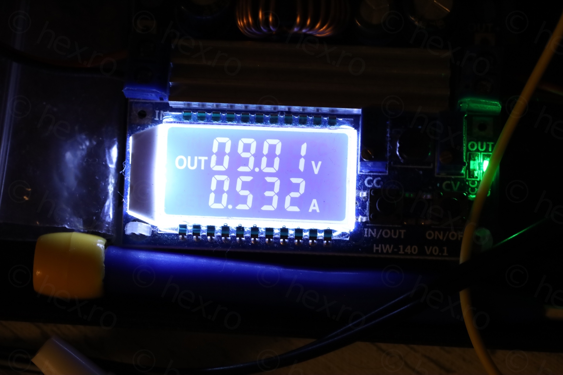
I checked for obvious shorts at the DC jack and the power rails, there were none. Decided to power on the thing, while watching the current draw as well as the temperatures.
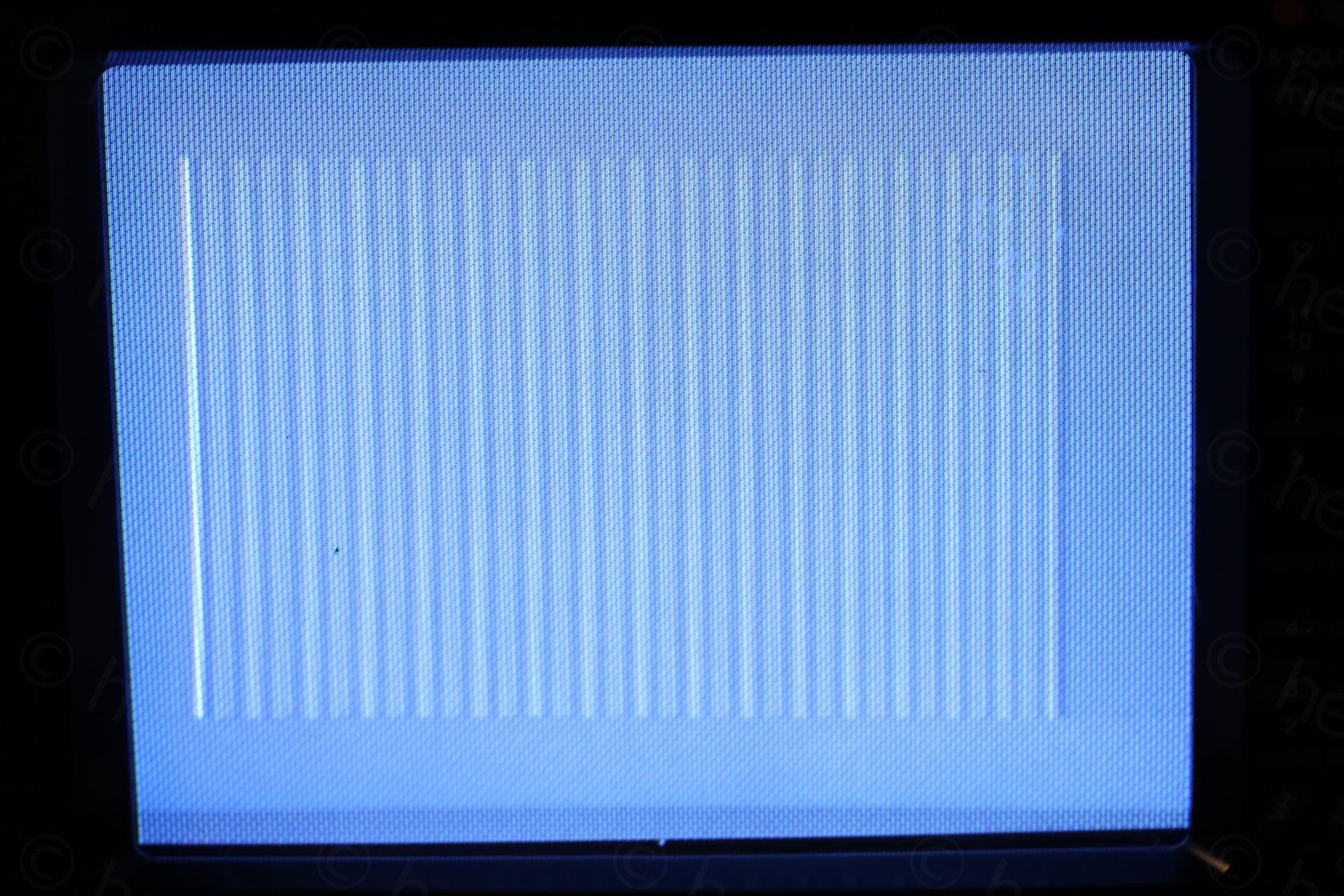
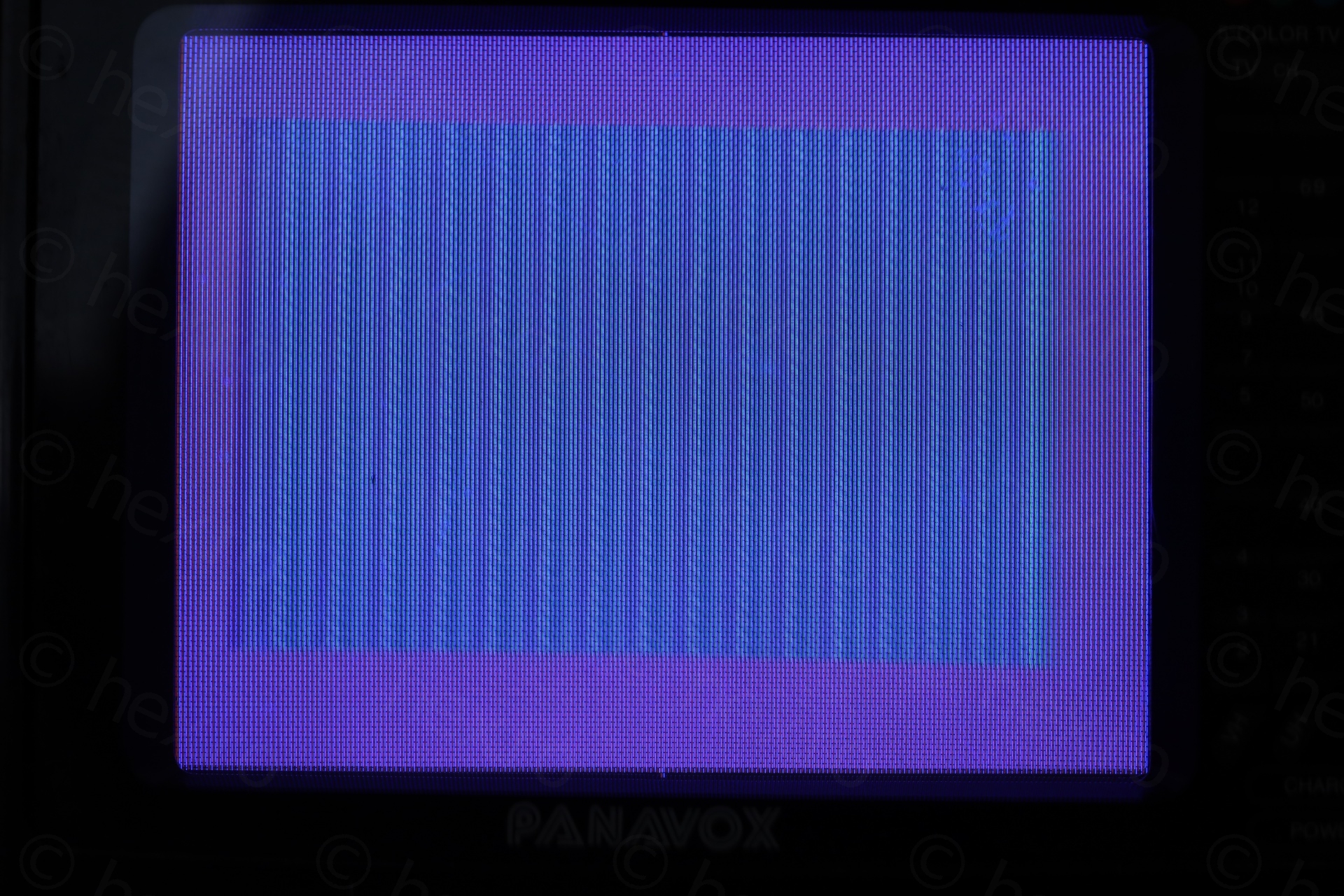
The screen was all gray out – no white border, and faint gray bards on the paper.
12V rail was around 6.98V
-5V was missing
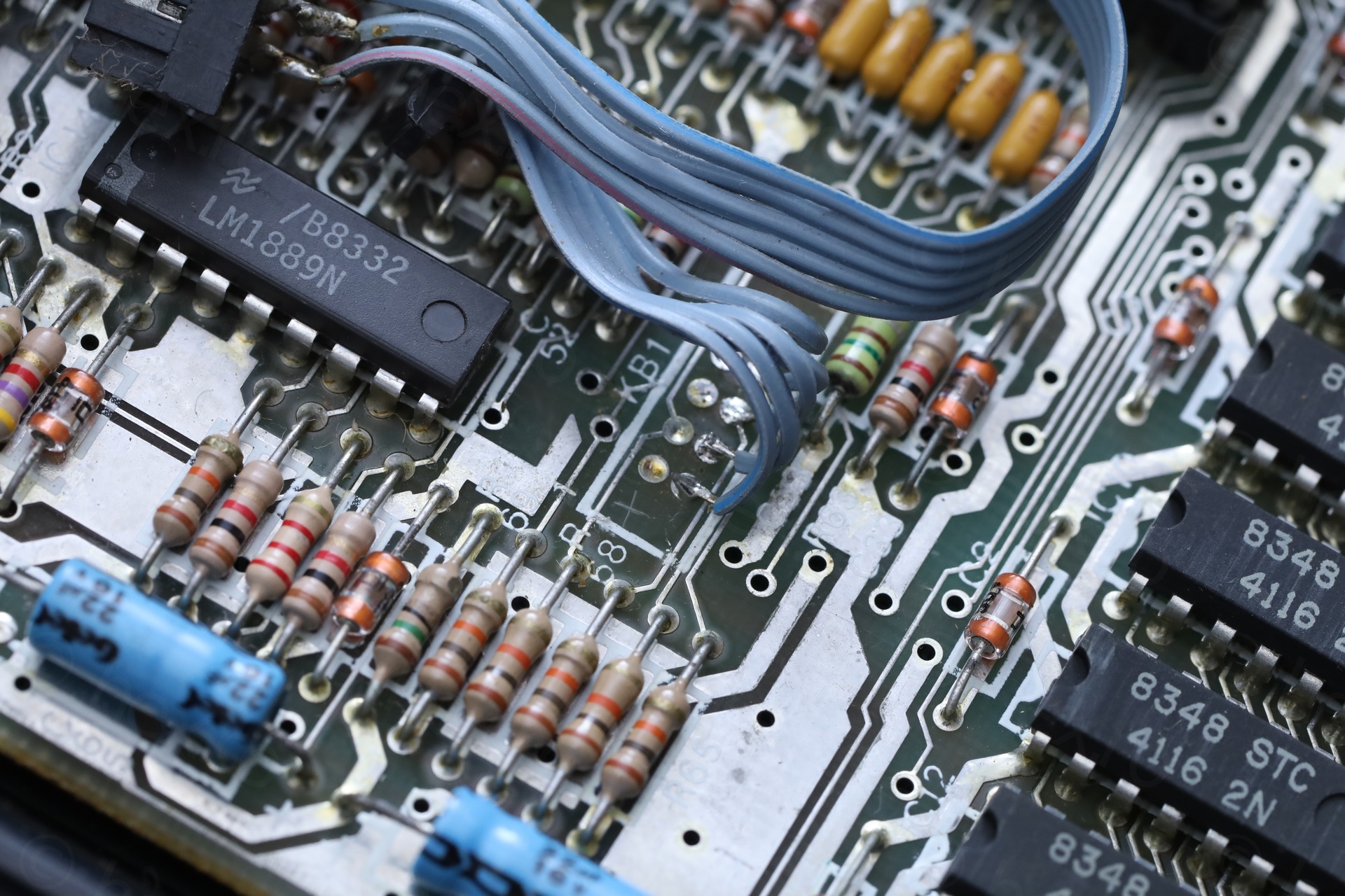
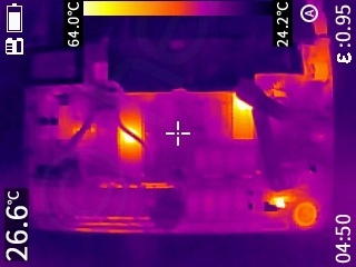
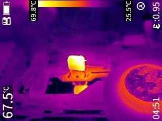
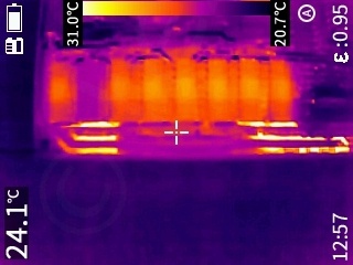
This explains the gray color, the LM1889 wasn’t even receiving its 12V. The computer wasn’t drawing much current, but the transistor for audio was very hot (kept turned on) causing the speaker nearby to heat up. One IC in the lower RAM was “cold” (the second one on the left).
Poor computer (and poor me).
Repairs
The most important was to try to get the voltages back.
TR4 – ECG123A ?!
I saw TR4 had the ECG123A installed. A quick glance of the datasheet told me it is unsuited. While it matches for voltage (maximum voltage is 75V vs original 45V), it is only rated for 0.8A collector current while the original is rated for 2A.
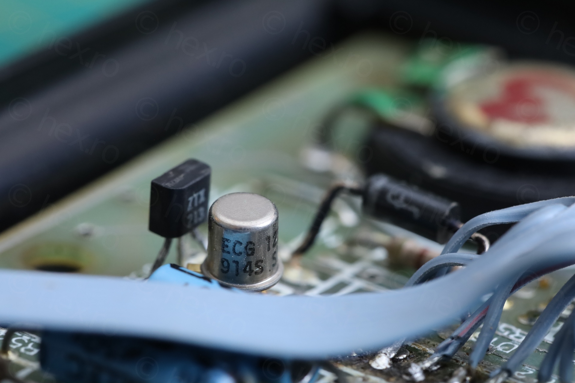
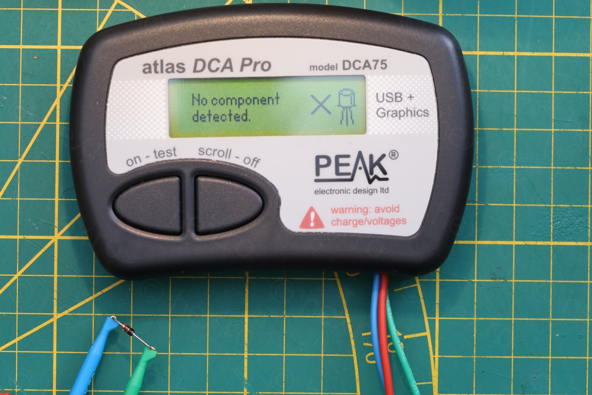
I took both transistors out for a quick check:
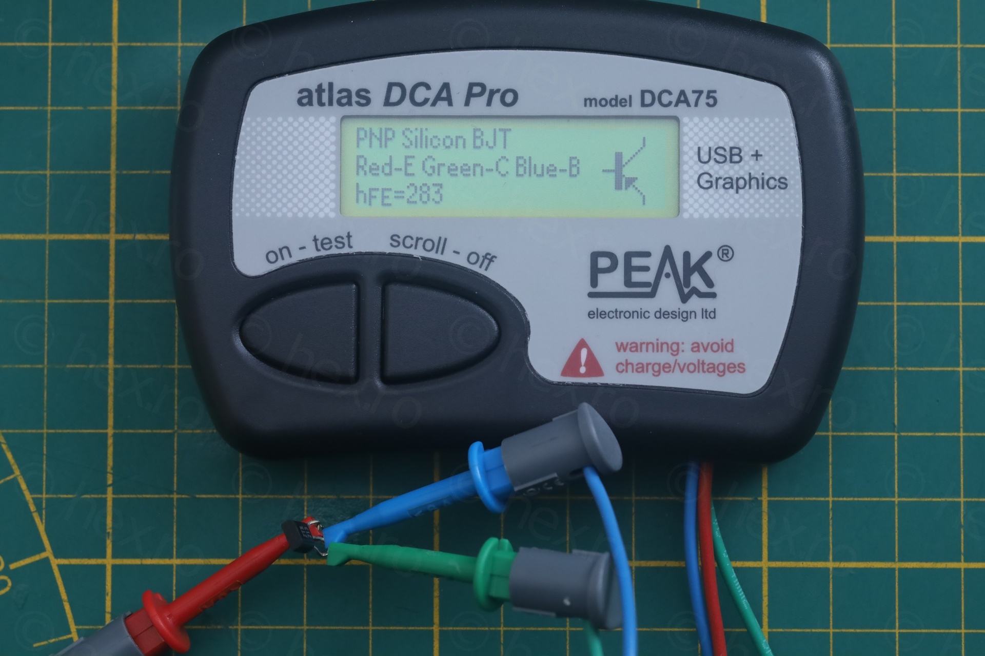
I decided to install the ZTX213 back, and for TR4 (ZTX650 – NPN, VCE 45 / 2A / 1W / 175MHz) to use ZTX690B (NPN, VCE 45V / 2A / 1W / 150MHz).
First step made. Voltages (and colors) are back, but still no sign of action from the poor computer.
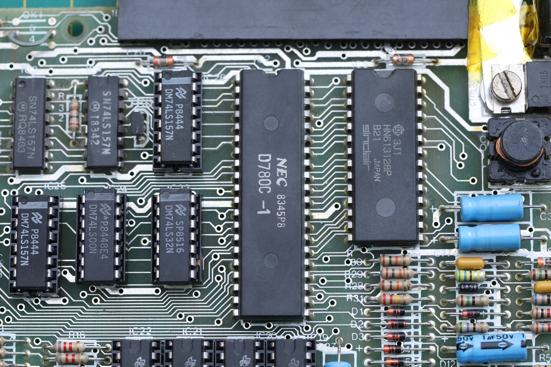
ULA – Dead
I decided to have a look at the CPU since it was too getting hot. No clock on pin 6. There was still chance the ULA may still be good. Checked continuity between ULA’s pin 39 and the LT of the X1 (14MHz) xtal, it is there. From the RT of X1 to RT of C73 -> it is there and from C73 LT to GND, it is there…
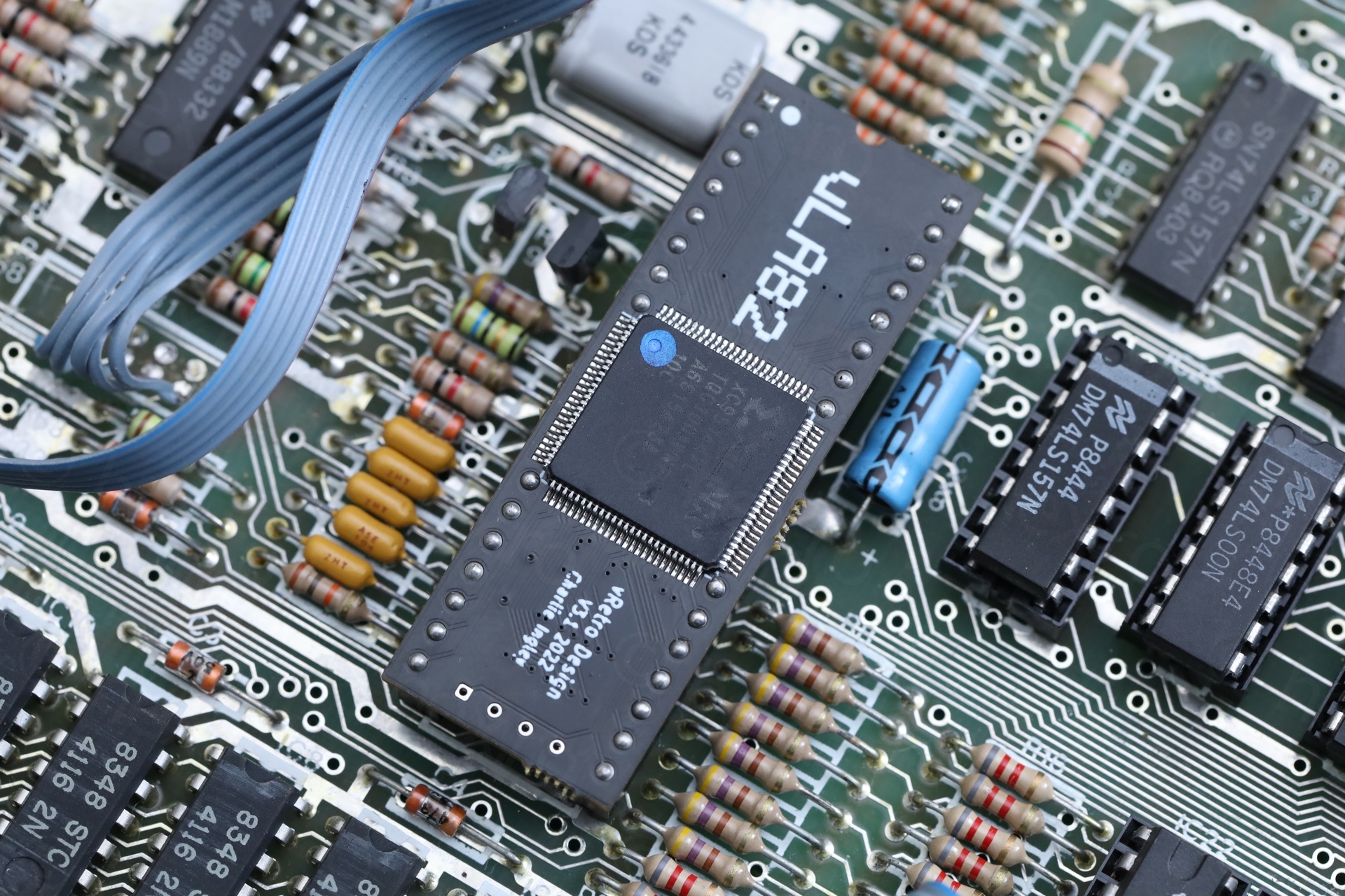
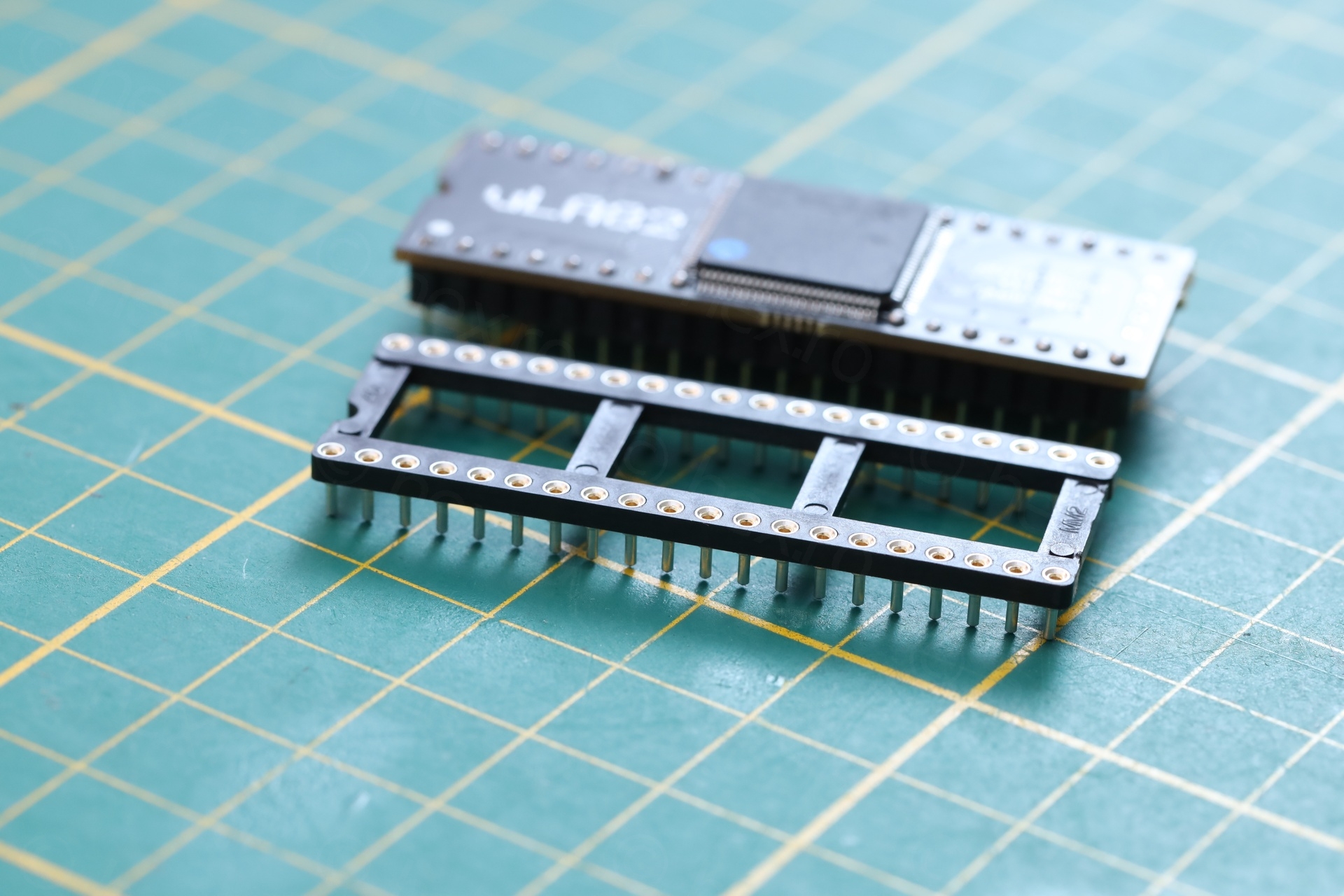
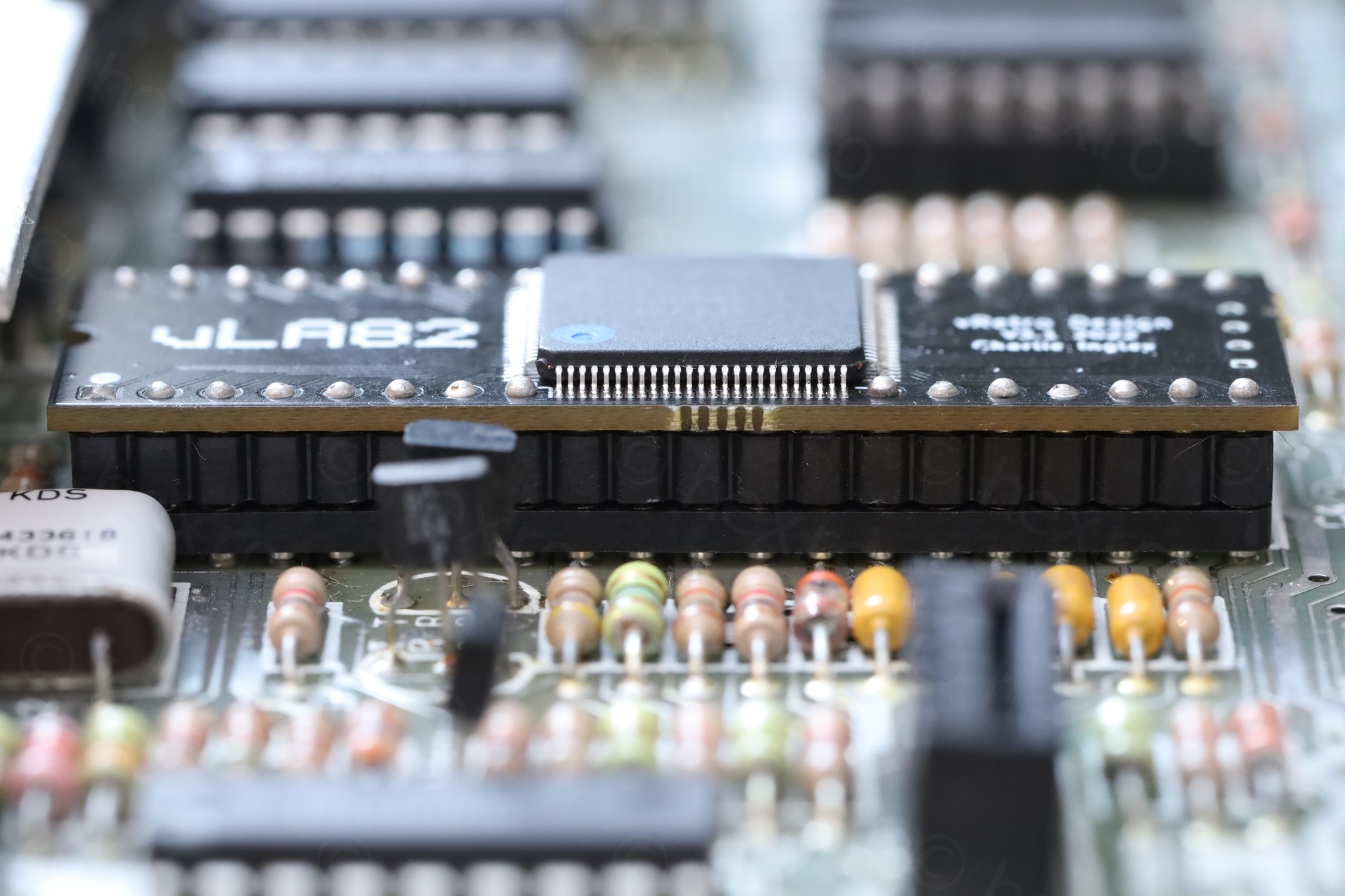
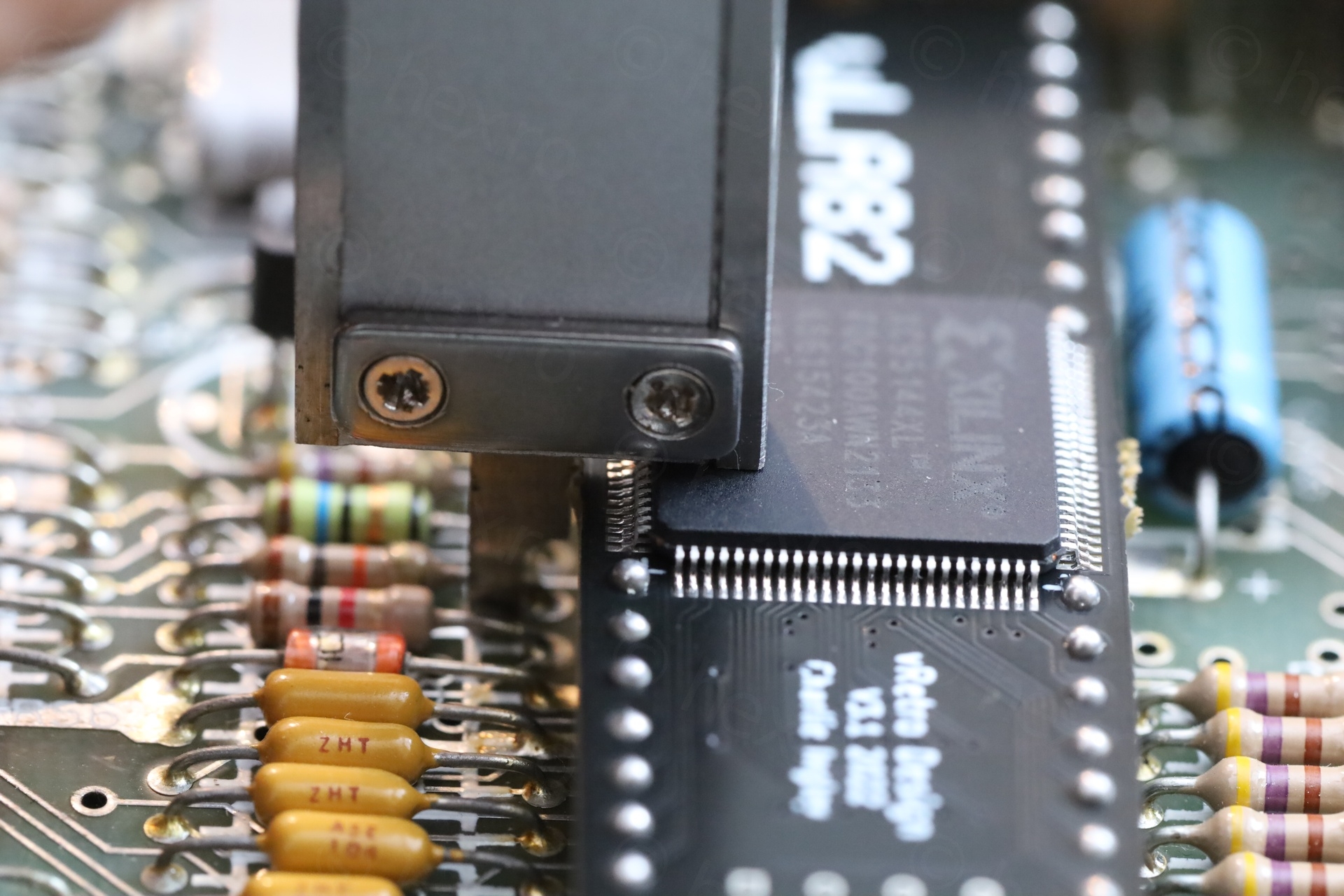
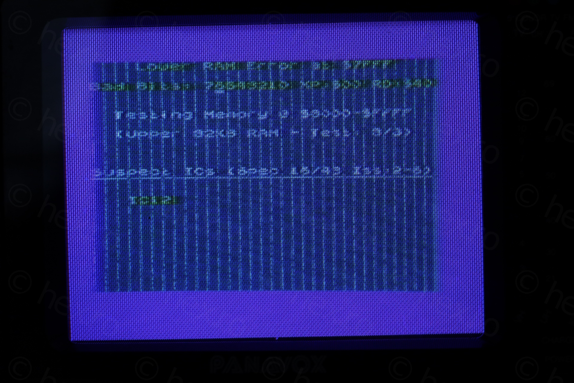
Swapped ULA with its modern replacement, a vLA82 – and the computer finally started booting from external ROM.
vLA82 – Installation Problems
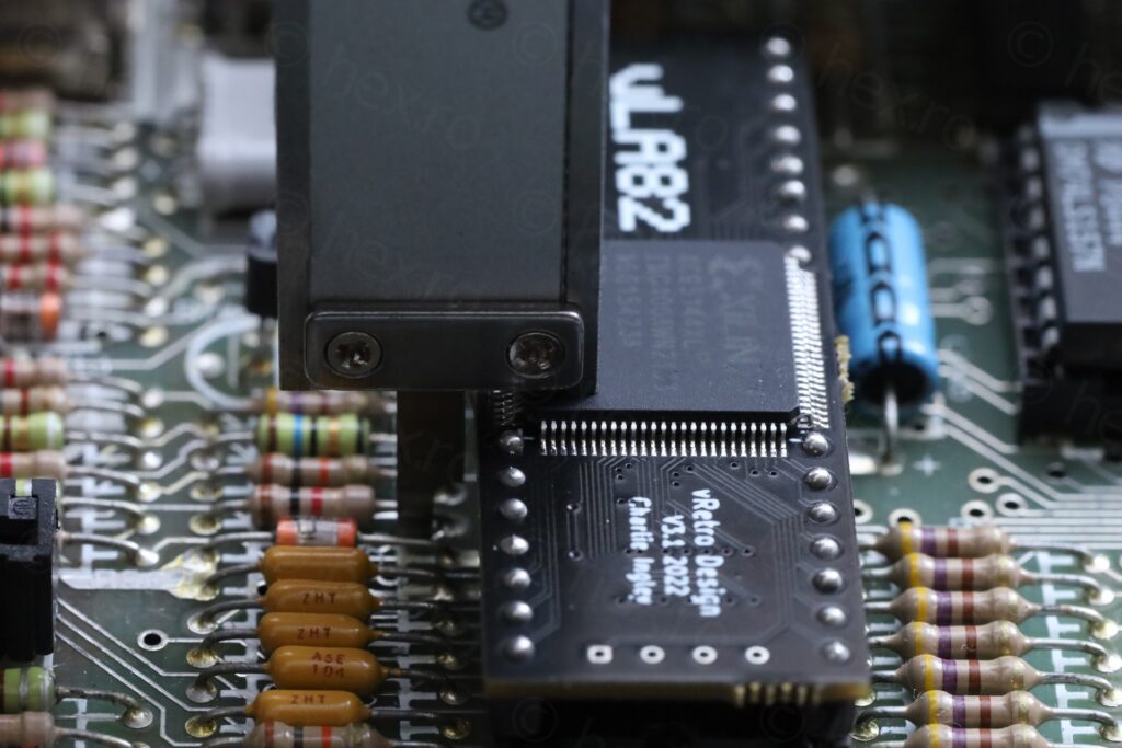
Although I found this later when the computer was almost ready to put back, vLA82 doesn’t properly fit the Sinclair ZX Spectrum. The top cover cannot be put back, as you can see from this video below:
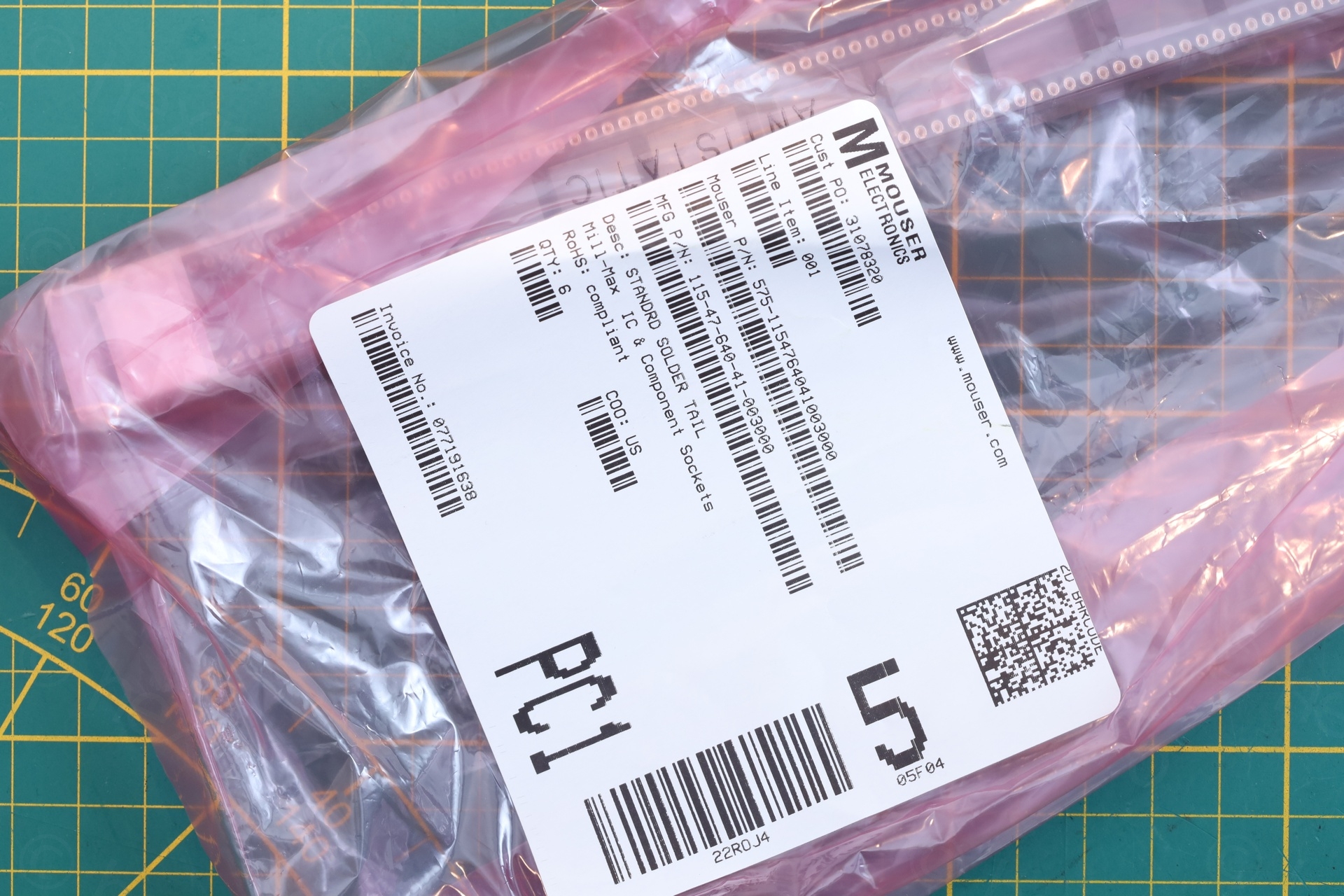
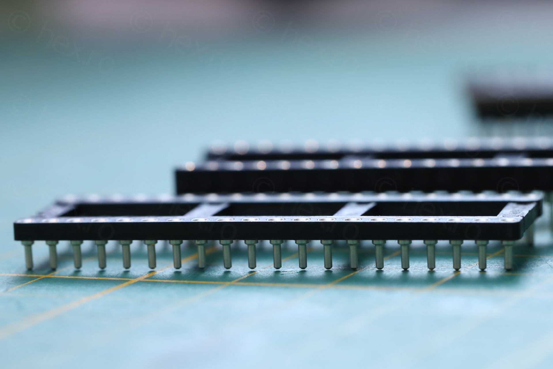
Mentioned in the vLA82 installation guide is that you may have to use a low profile socket. The low profile socket was not available on the Etsy store where I bought the vLA82 from and it was difficult to find out which socket is needed. On top of that, no low profile sockets were available from EU / UK. I had to have them shipped from US.
I settled on Mill-Max 115-47-640-41-003000 available here https://www.mouser.be/ProductDetail/575-1154764041003000 after putting a large enough order so that the shipping / custom tax / handling fees are handled by Mouser.
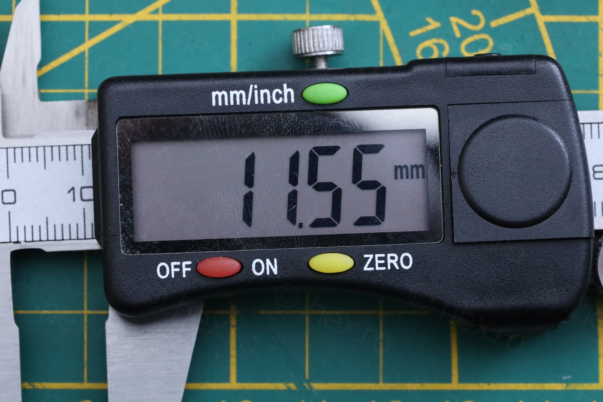
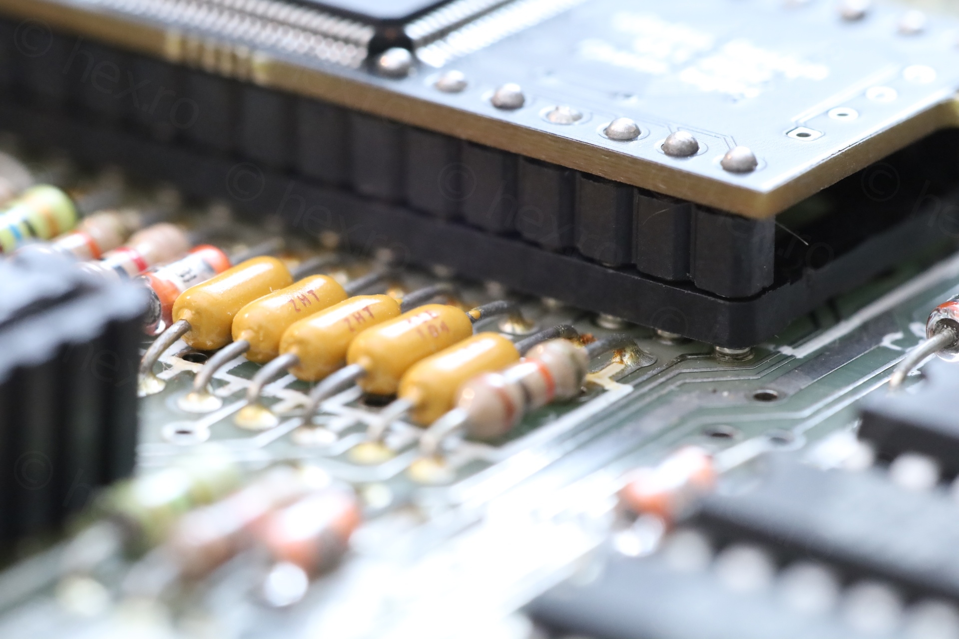
Coming back to the problem: when installed in the existing ULA socket, the vLA82 sits at about 11.5mm tall above the board – which makes it impossible to put the top cover back onto the computer:
After waiting for about a week, the new sockets arrived:
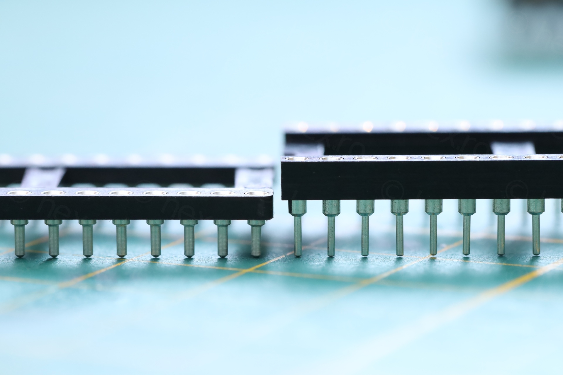
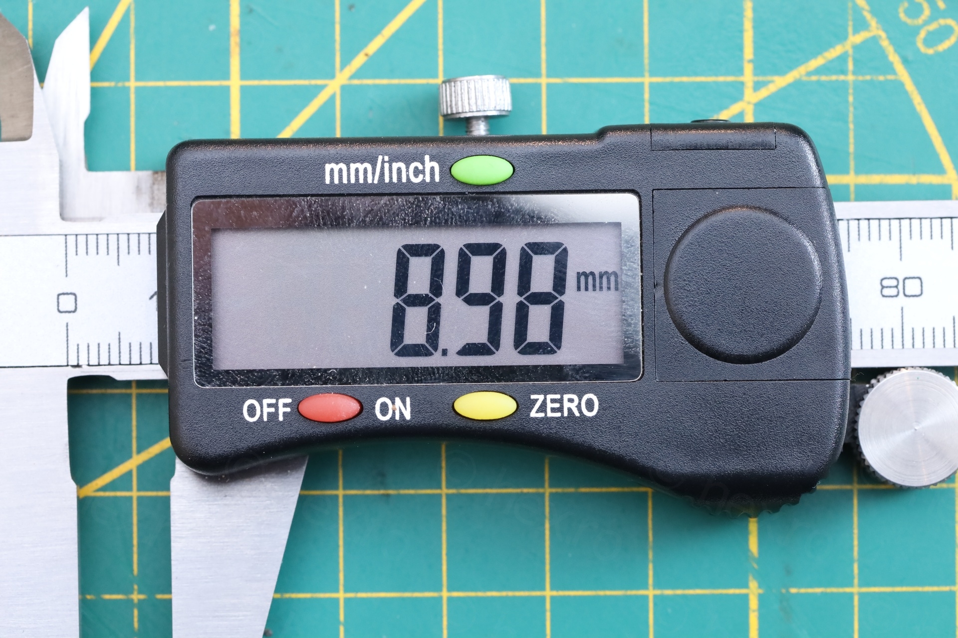
I took the old socket out, put the new one in – the vLA82 finally fits and sits at 9mm tall, allowing the top case to be properly seated:
While I am very grateful that vLA82 exists, it usually feels bad if ULA is dead. The ULA and ROM chips are what make Sinclair Spectrum special. It feels “too modern” having them replaced – no better than running Fuse on a Rasberry PI. However, this is not the case with this specific Spectrum. Here, weirdly, I feel like the Keyboard is its essence. I don’t feel bad at all swapping the ULA 🙂 to keep it going.
Now back to the initial repairs.
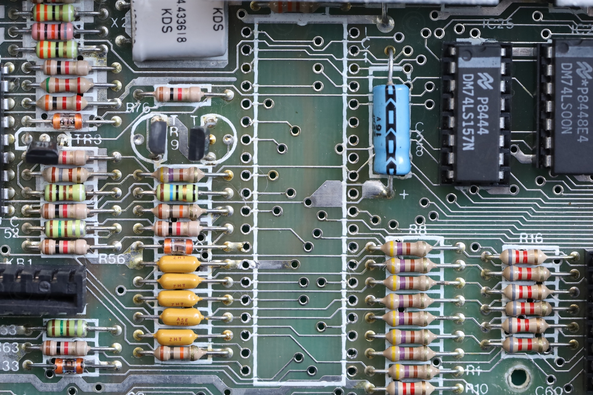
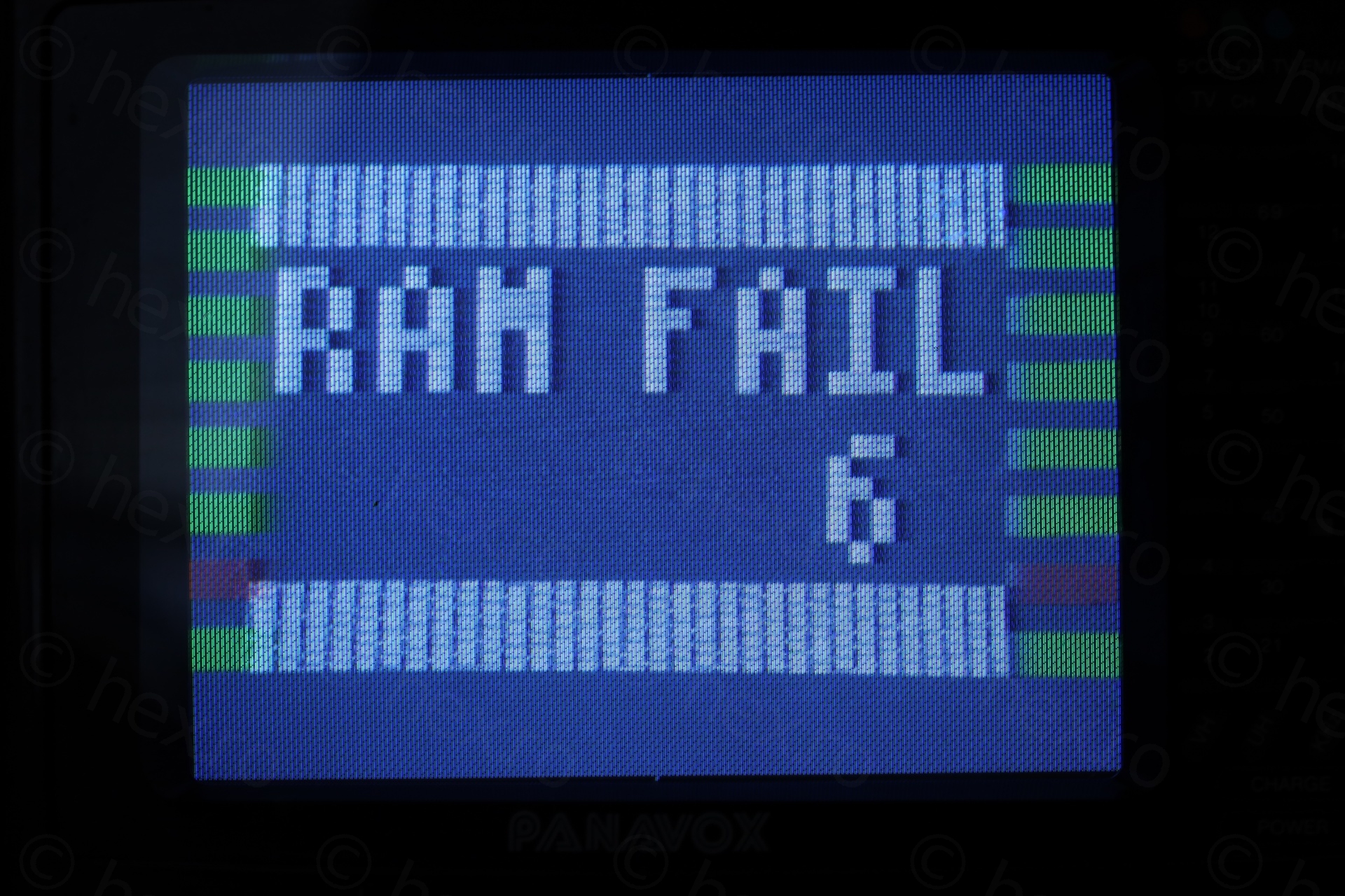
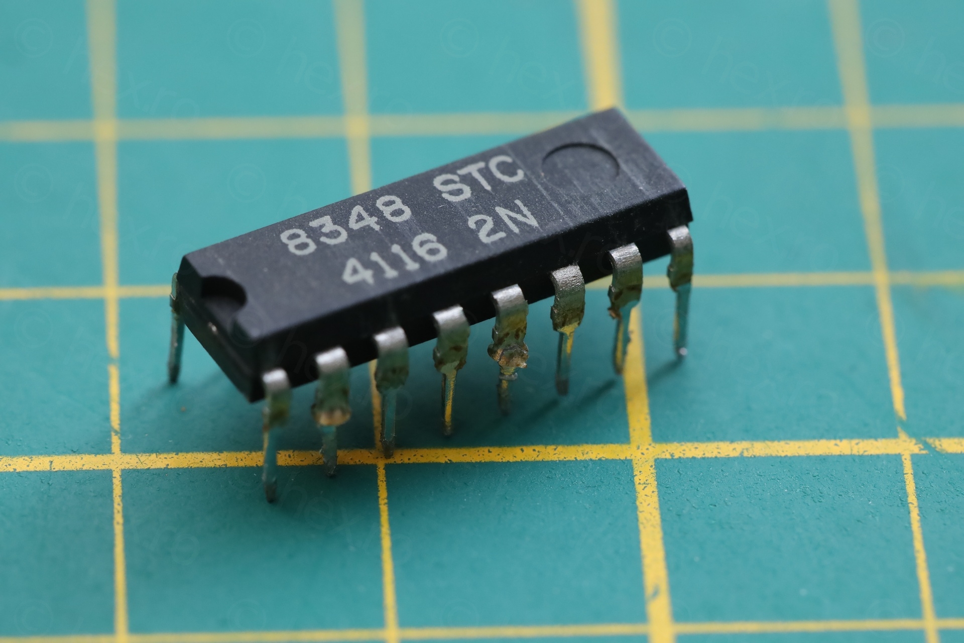
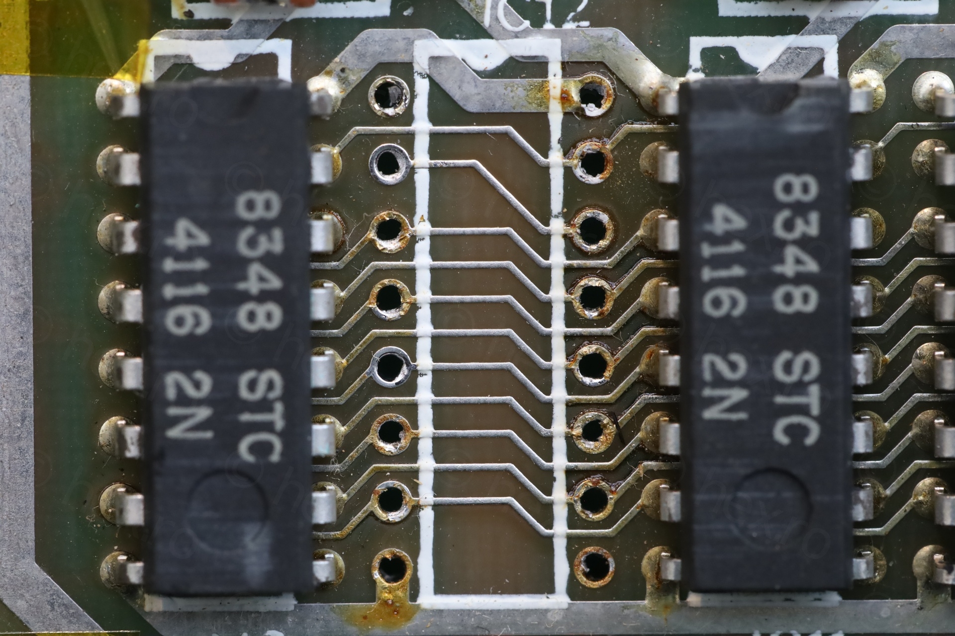
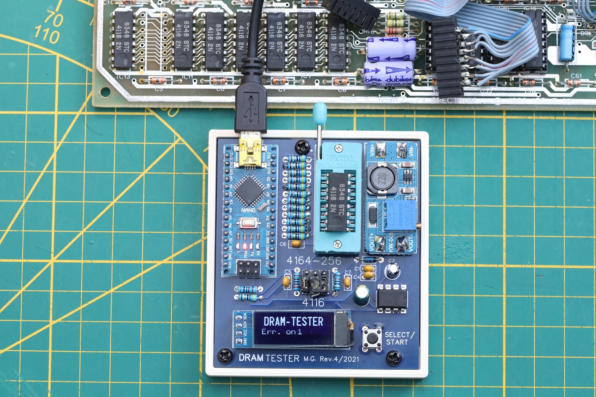
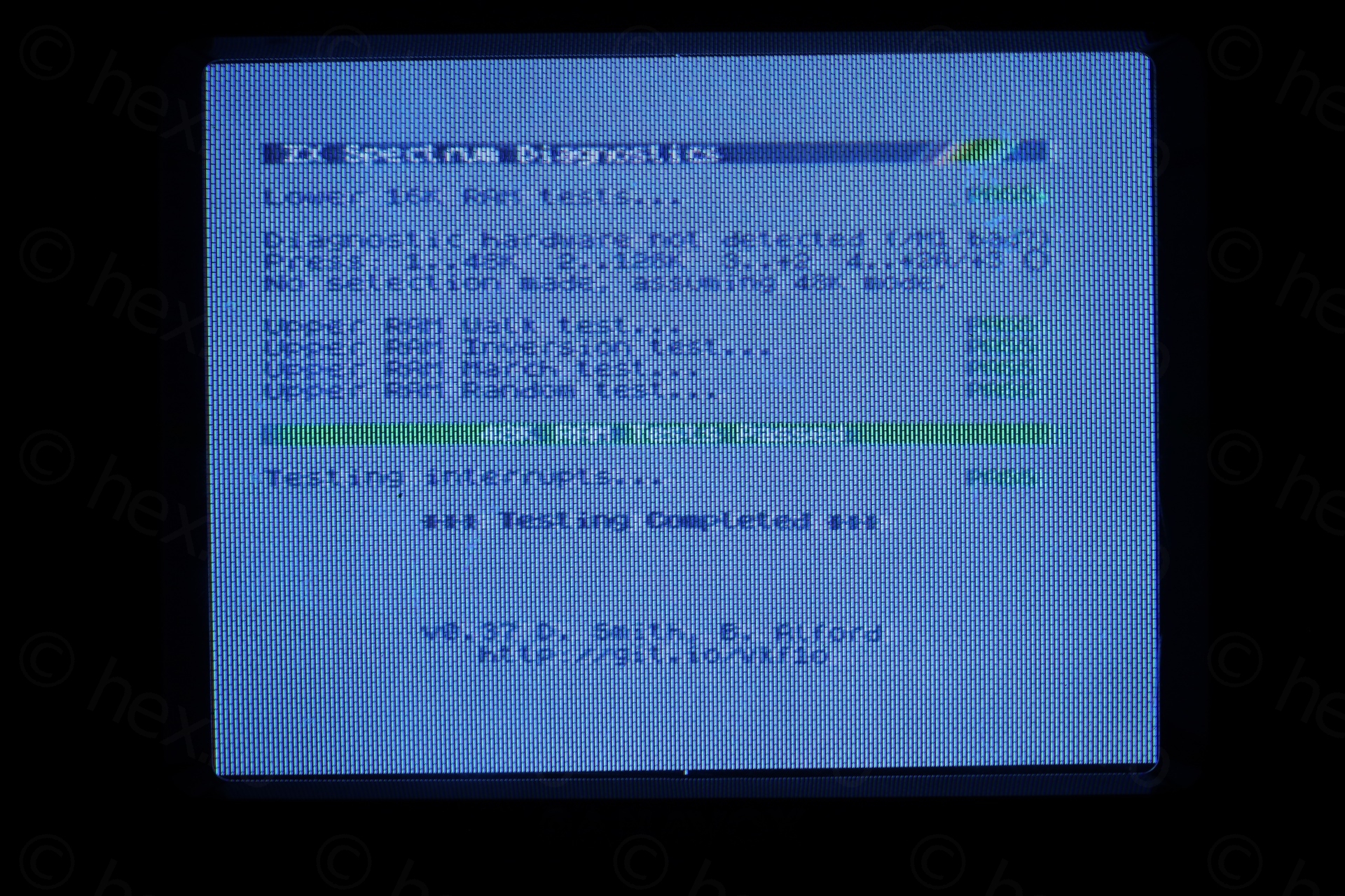
IC12 – Ram Fail 6
Since I could finally run an external diagnostic ROM, this confirmed the initial discovery via IR camera. The 2nd IC from the LEFT (IC12) is dead:
At least, only one memory IC was faulty. Not so much to de-solder.
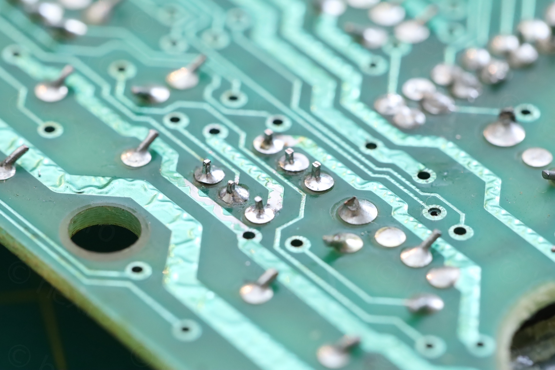
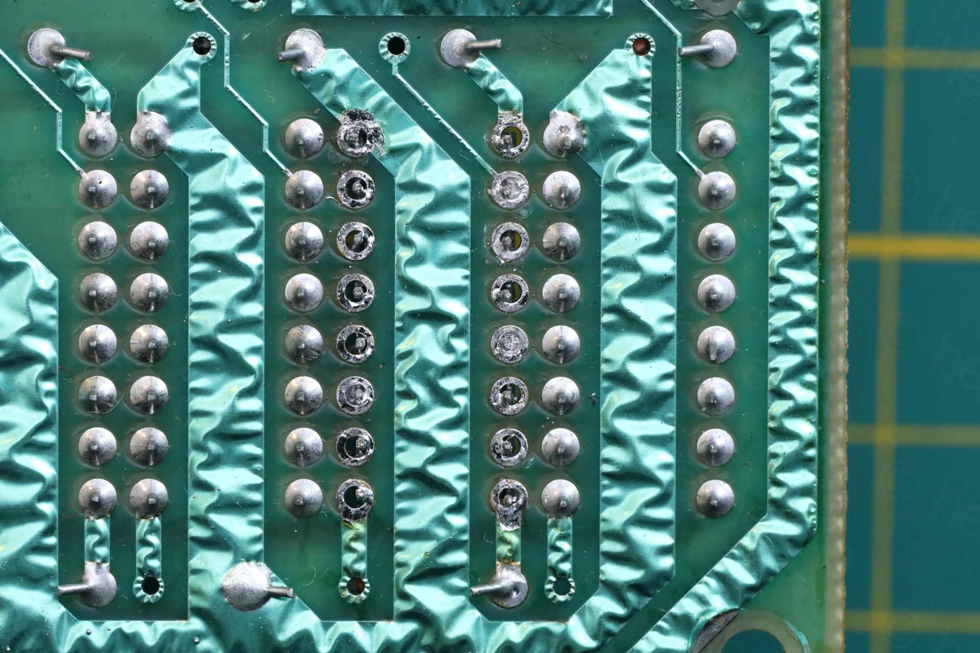
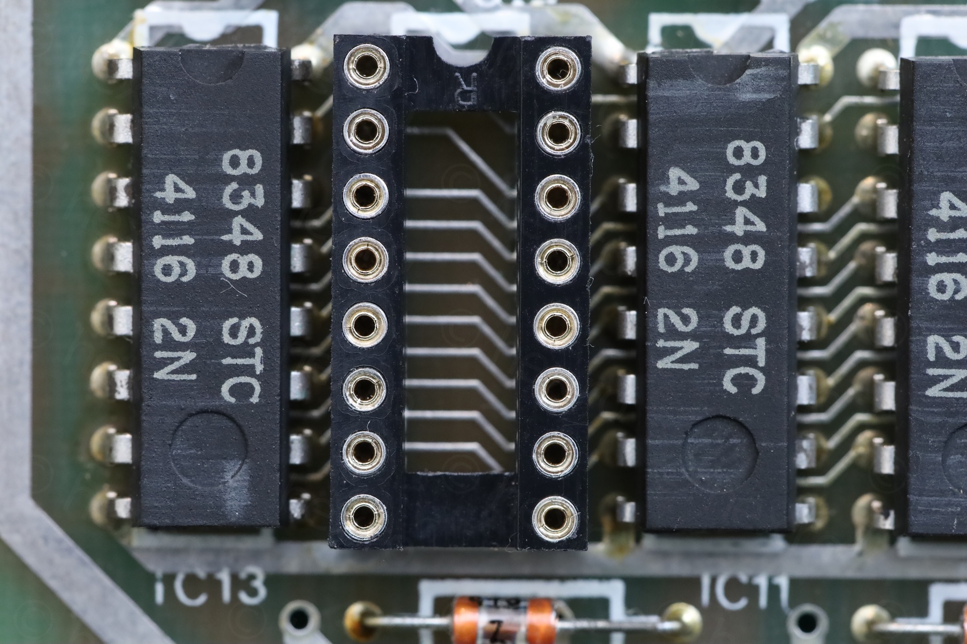
I got to the point where I can now safely de-solder any memory IC without lifting any pads:
a) Add low melt solder to the the existing solder joints.
b) Clean as much as possible with a electrical vacuum suction pump.
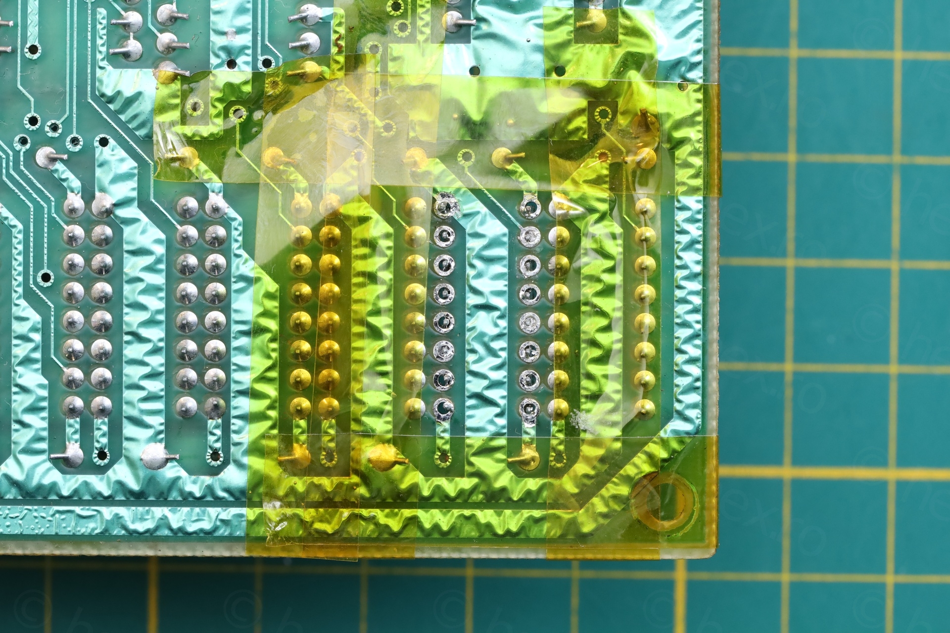
c) Protect the areas around the IC using Kapton tape
d) Use a heat gun set on medium airflow and about 250C.
I just gently push on the pins using a screw driver, and then I use a tooth pick (while still applying heat) through the holes- to push the IC pins further down. Eventually, the IC falls down on the carton underneath. I use a carton so that the cutting mat doesn’t melt due to the heat.
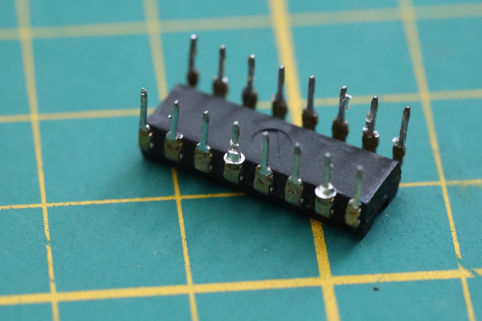
Measuring it, myeah, it is not good:
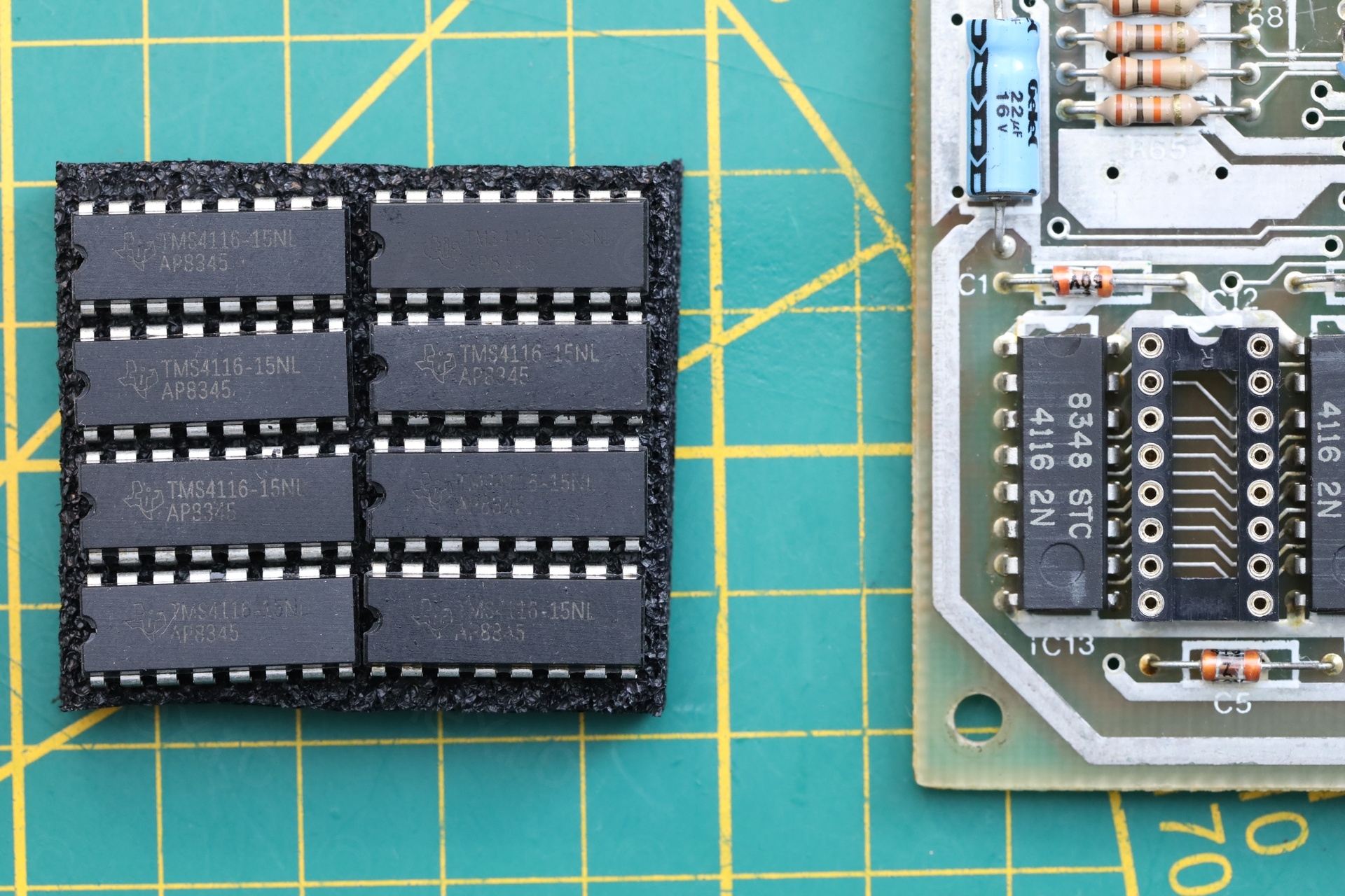
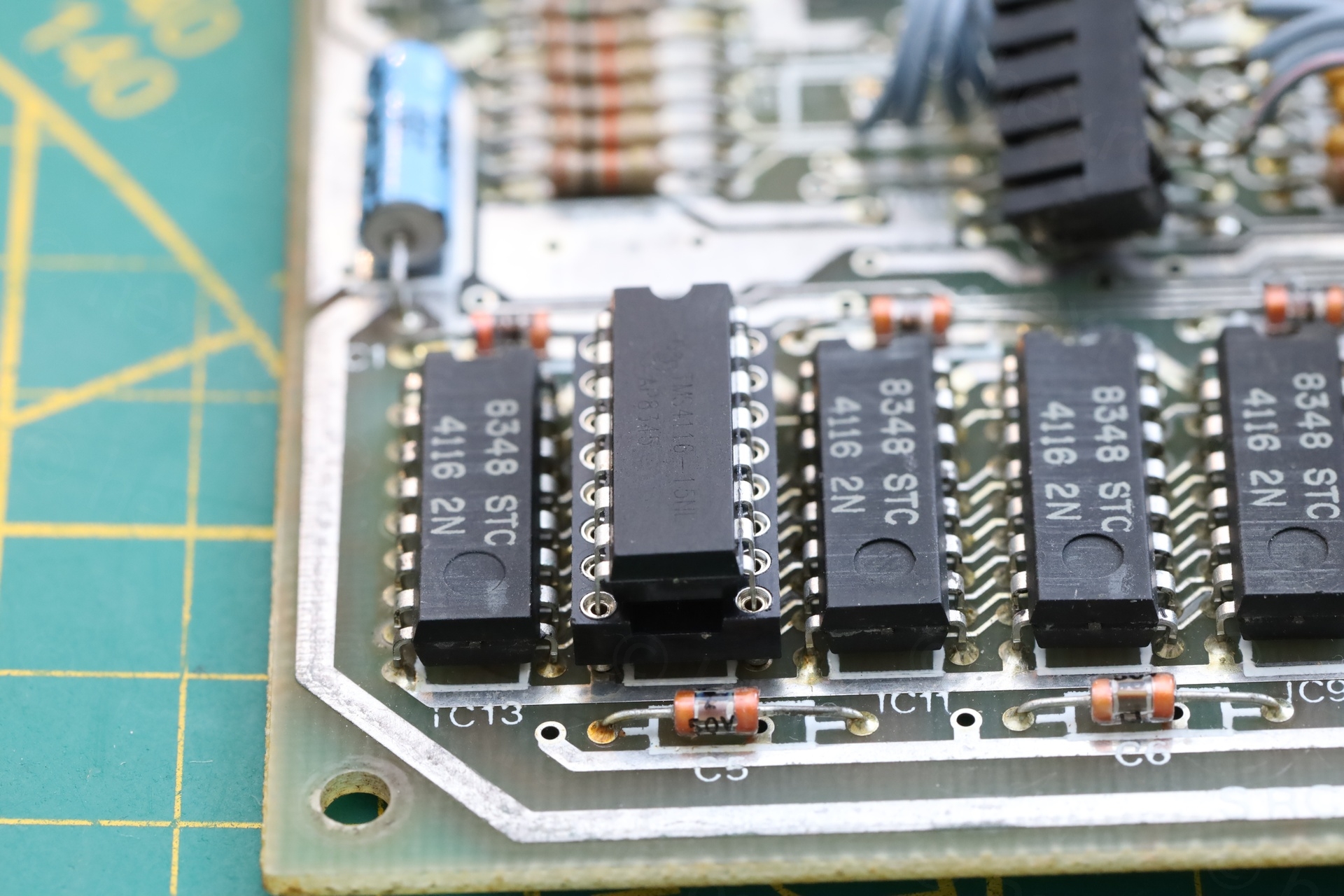
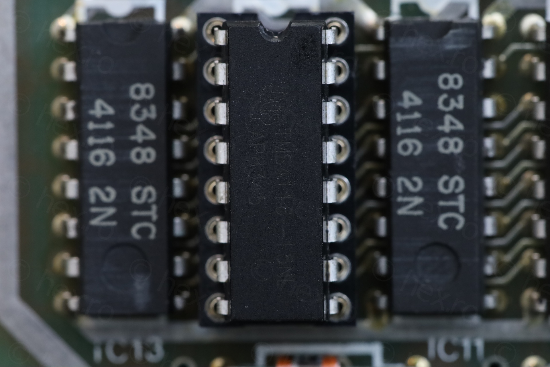
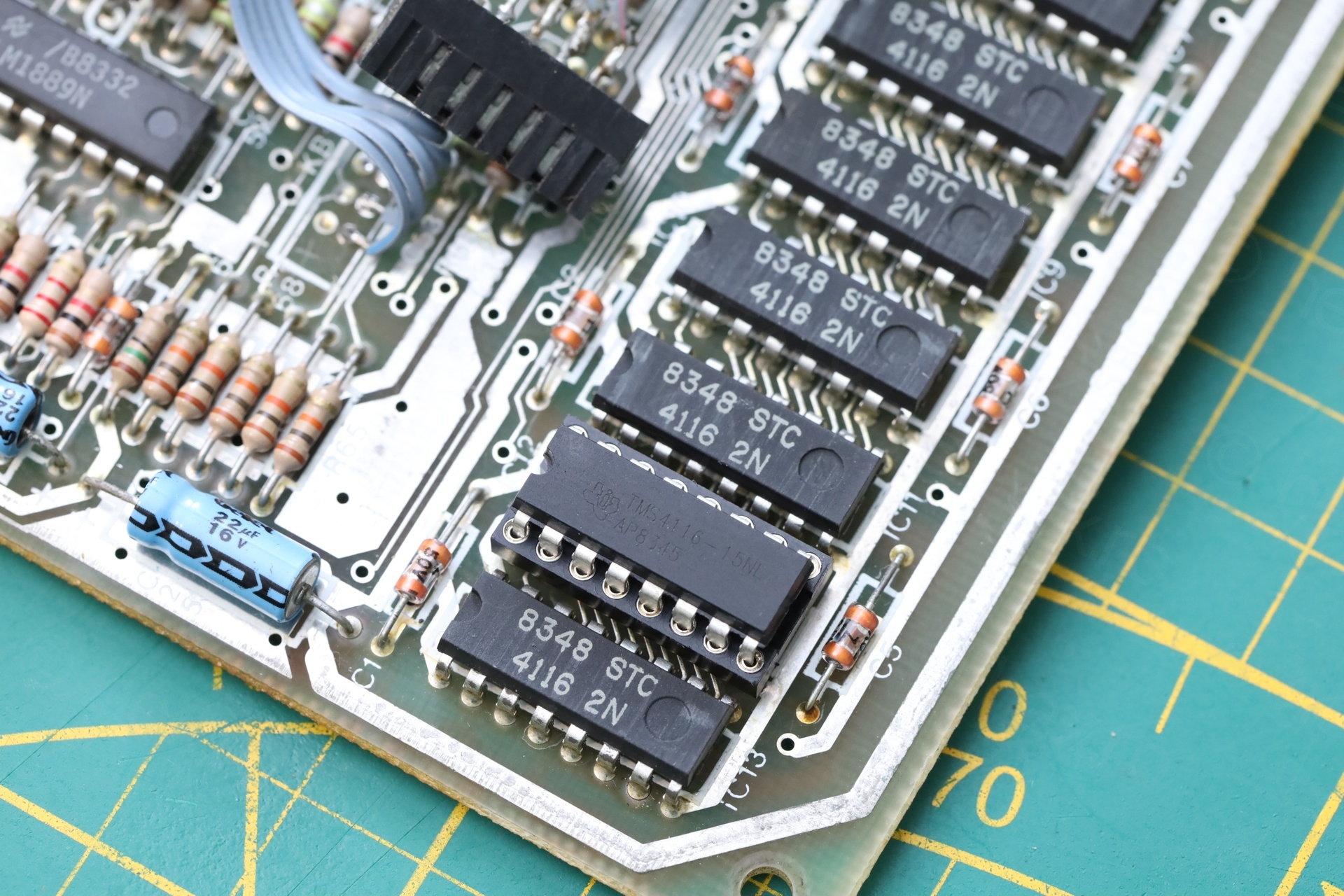
Installed a socket followed by a suitable replacement for the STC 4116 in the form of TMS4116-15NL. Finally, memory tests pass:
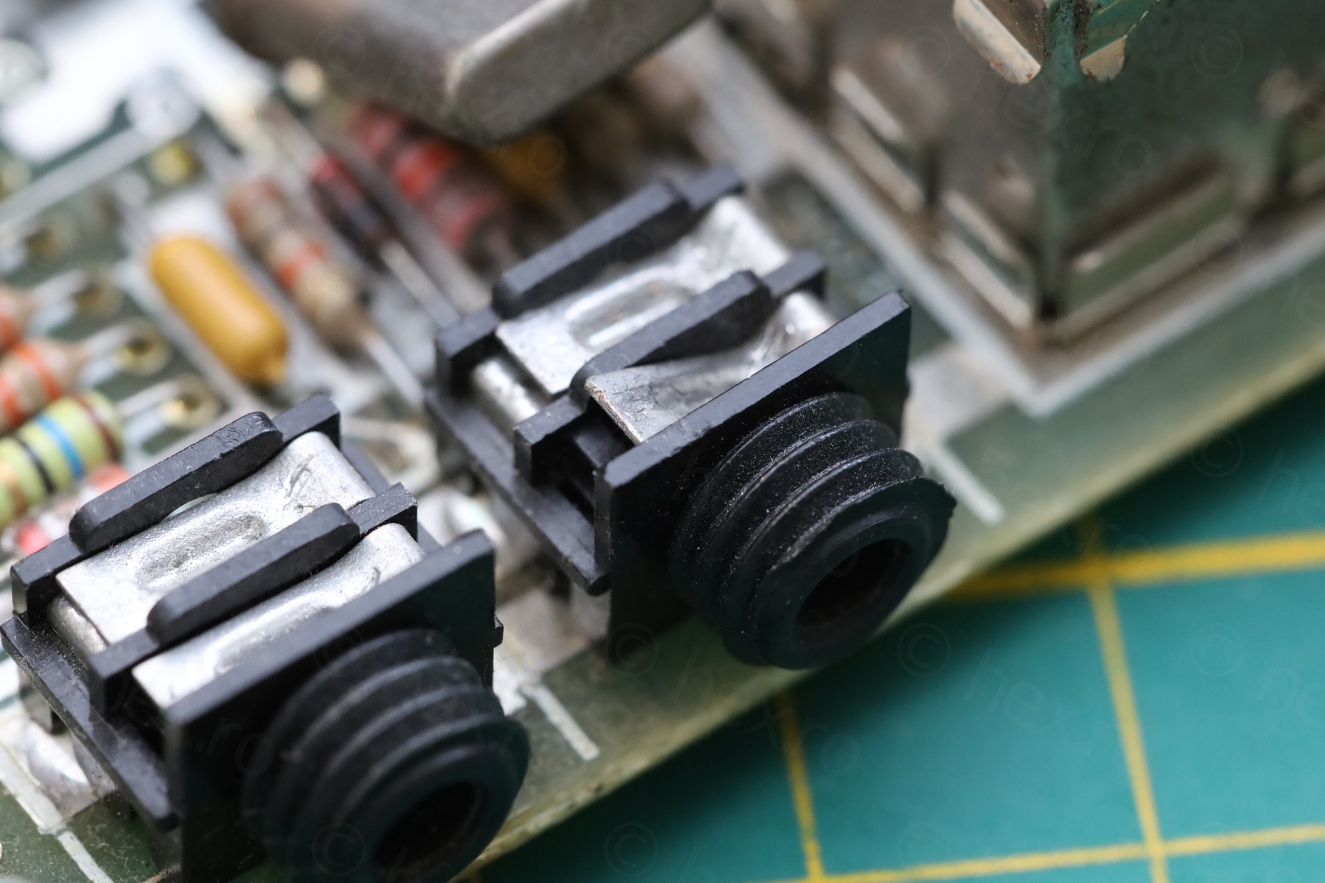
Audio jack – Surgery
Next I focused on one of the audio jacks. One of the contacts was bent outwards (which could have been the reason that somebody decided to cut a cable in half and solder it to both jacks). Lots of heat needed here.
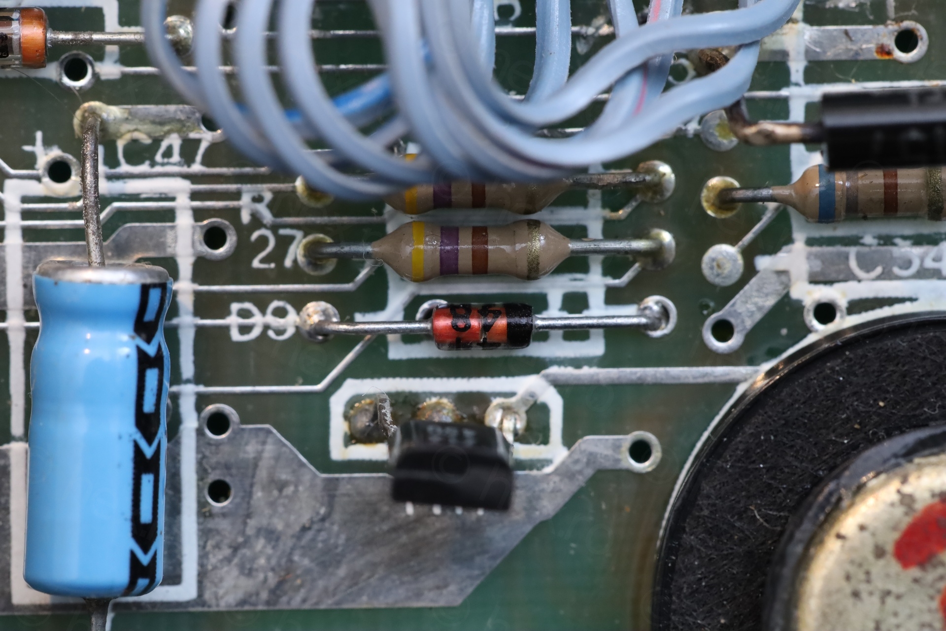
Melted speaker – D9 open
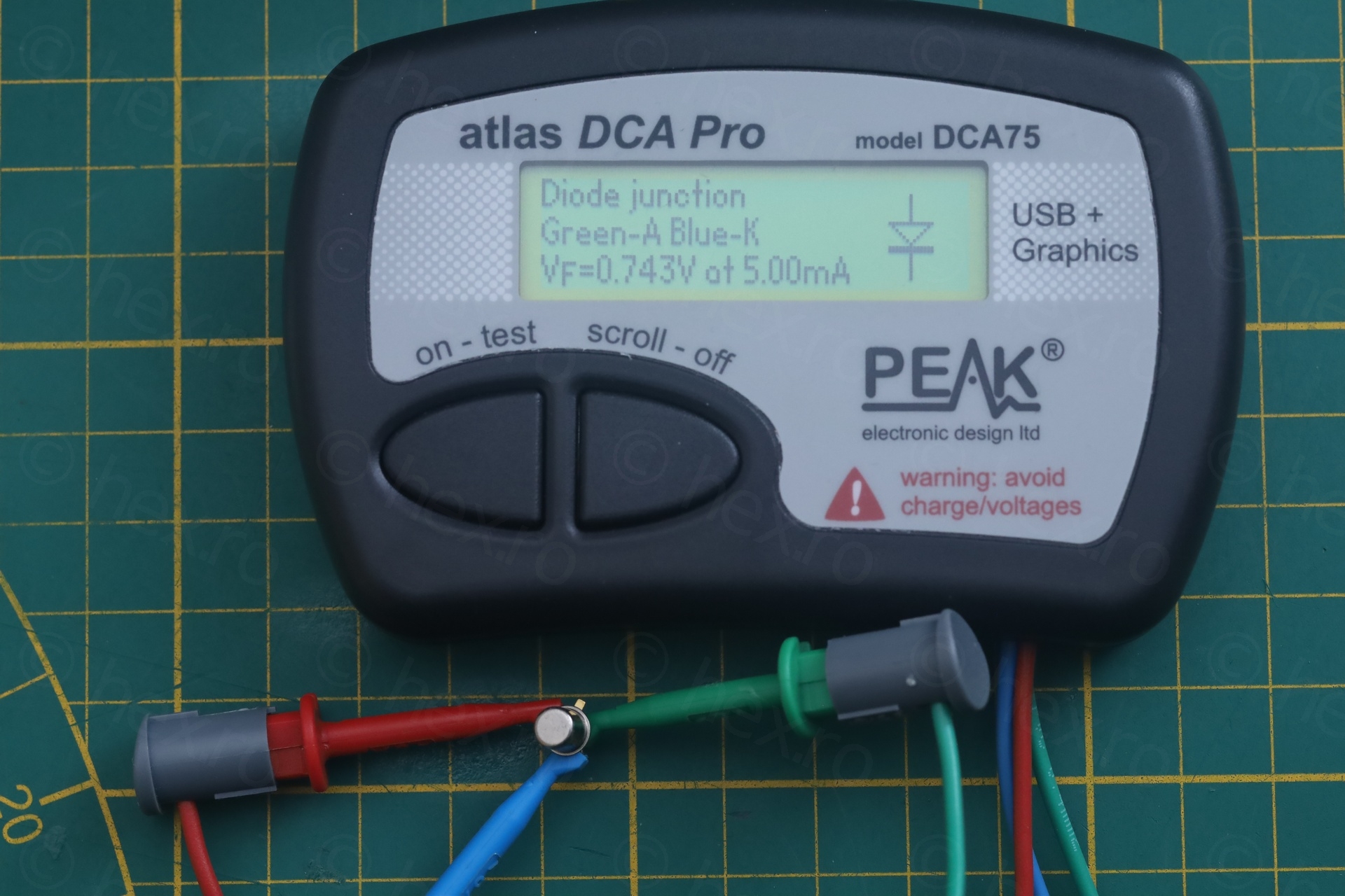
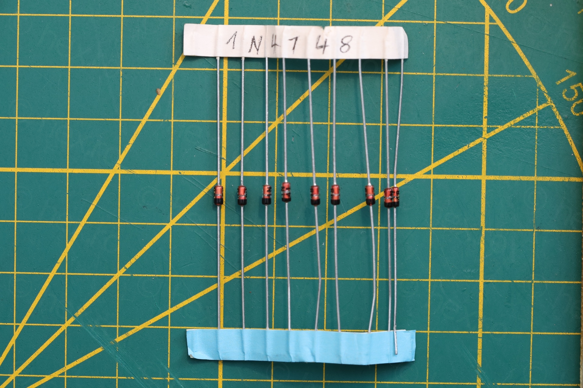
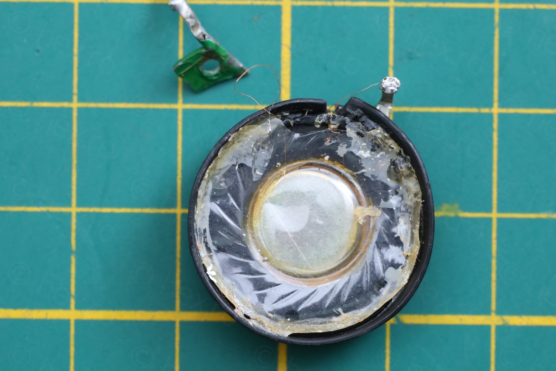
The speaker was very faint in sound. Looking around I found the D9 open. More trouble – replacing the diode with a good 1N4148 did not bring the loudness back.
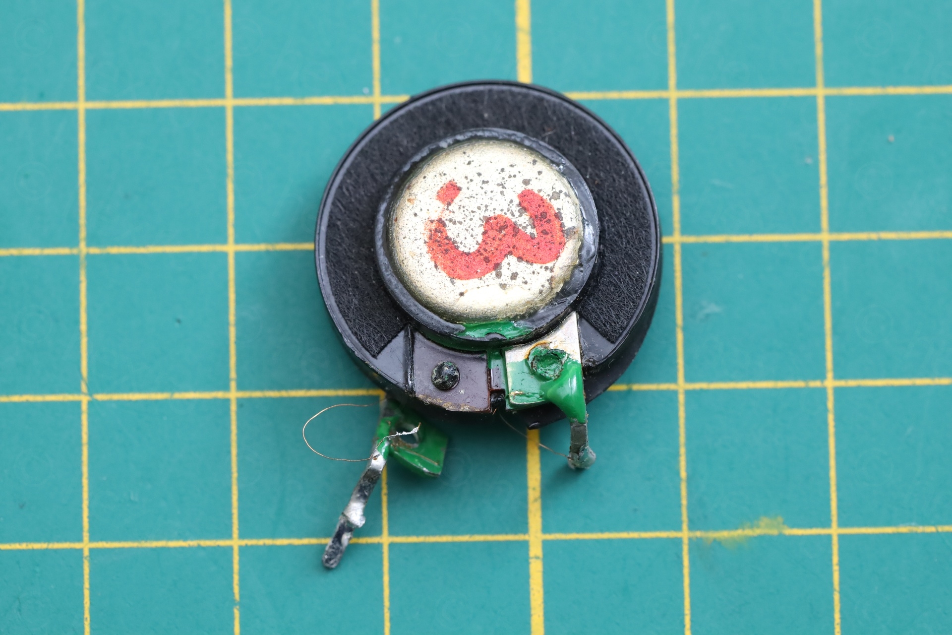
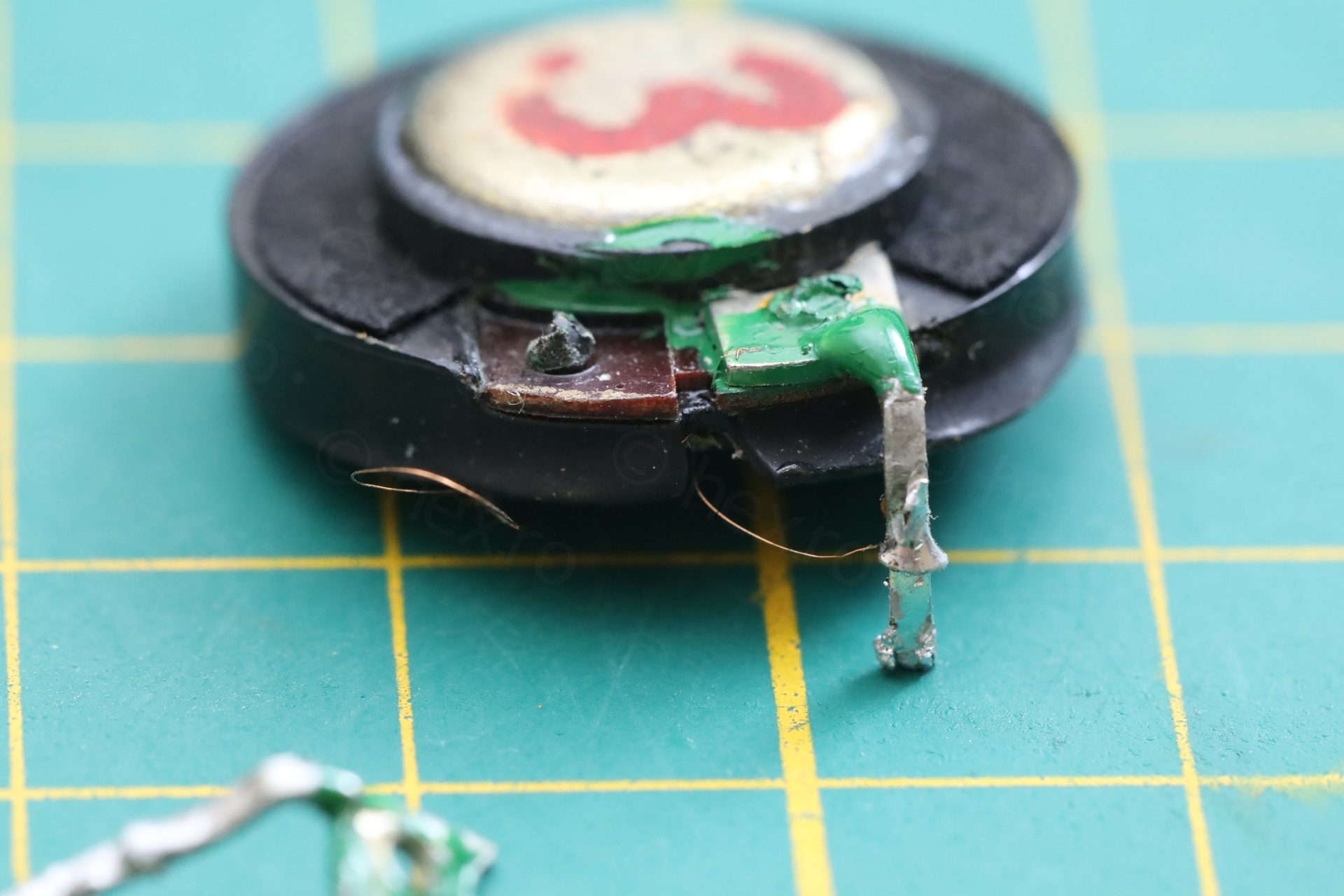
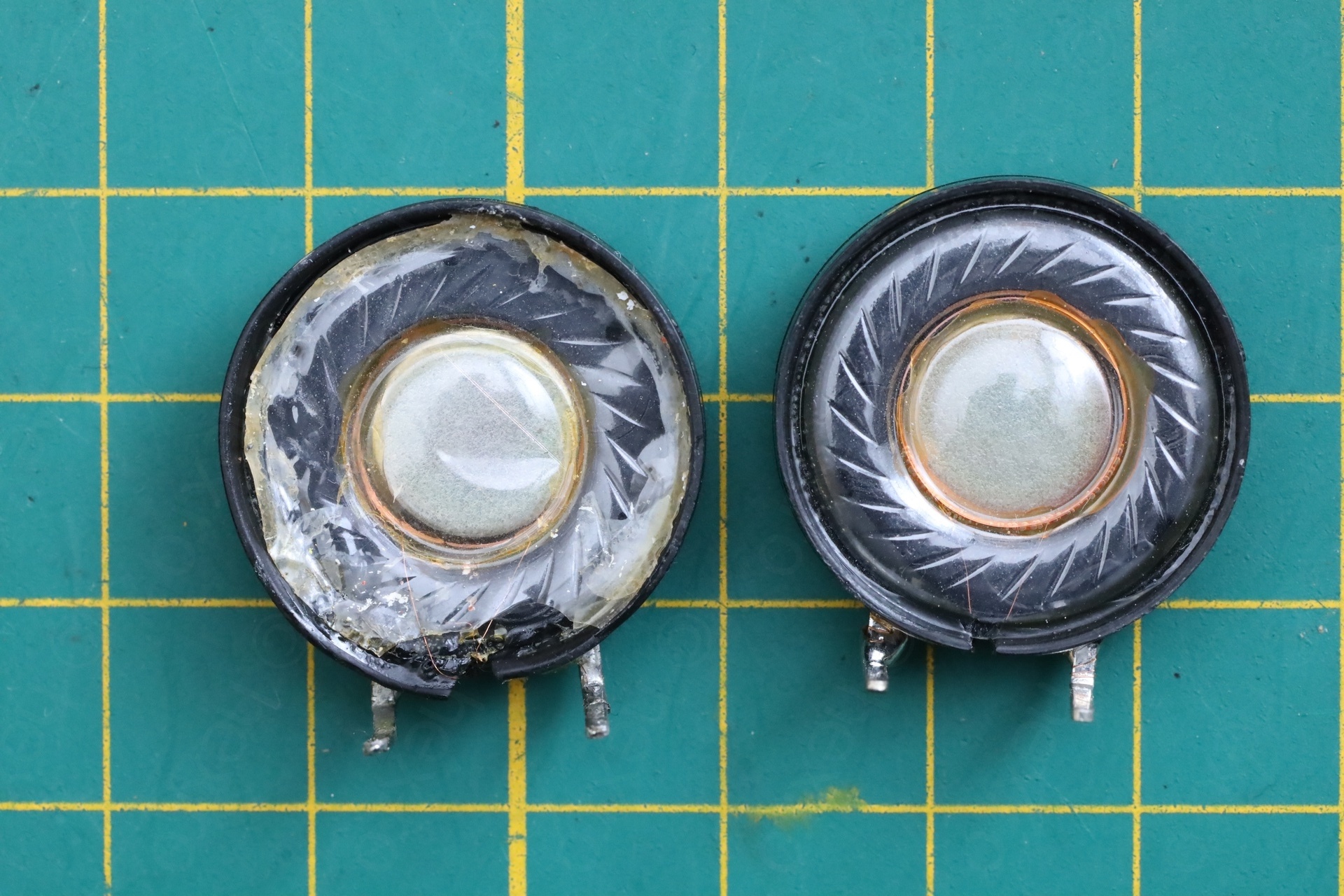
Taking the speaker out, another surprise, its was totally melted. I had to wait for some replacement speakers to arrive first, before completing this repair.
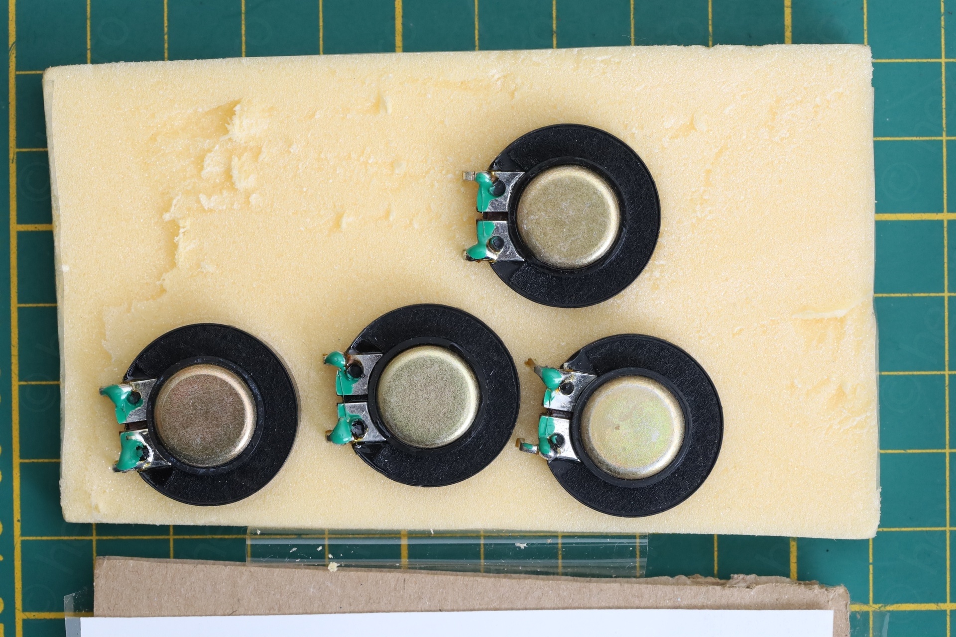
One word of caution. Although I ordered 4 new speakers but found one of them to be open. Thankfully I tested them, looking to see if the are close to 40Ω.
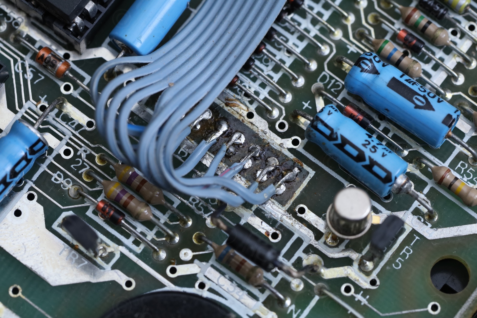
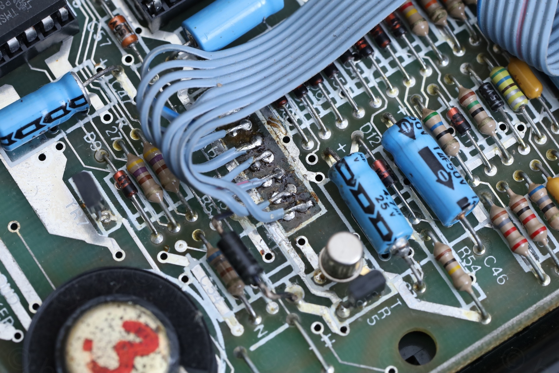
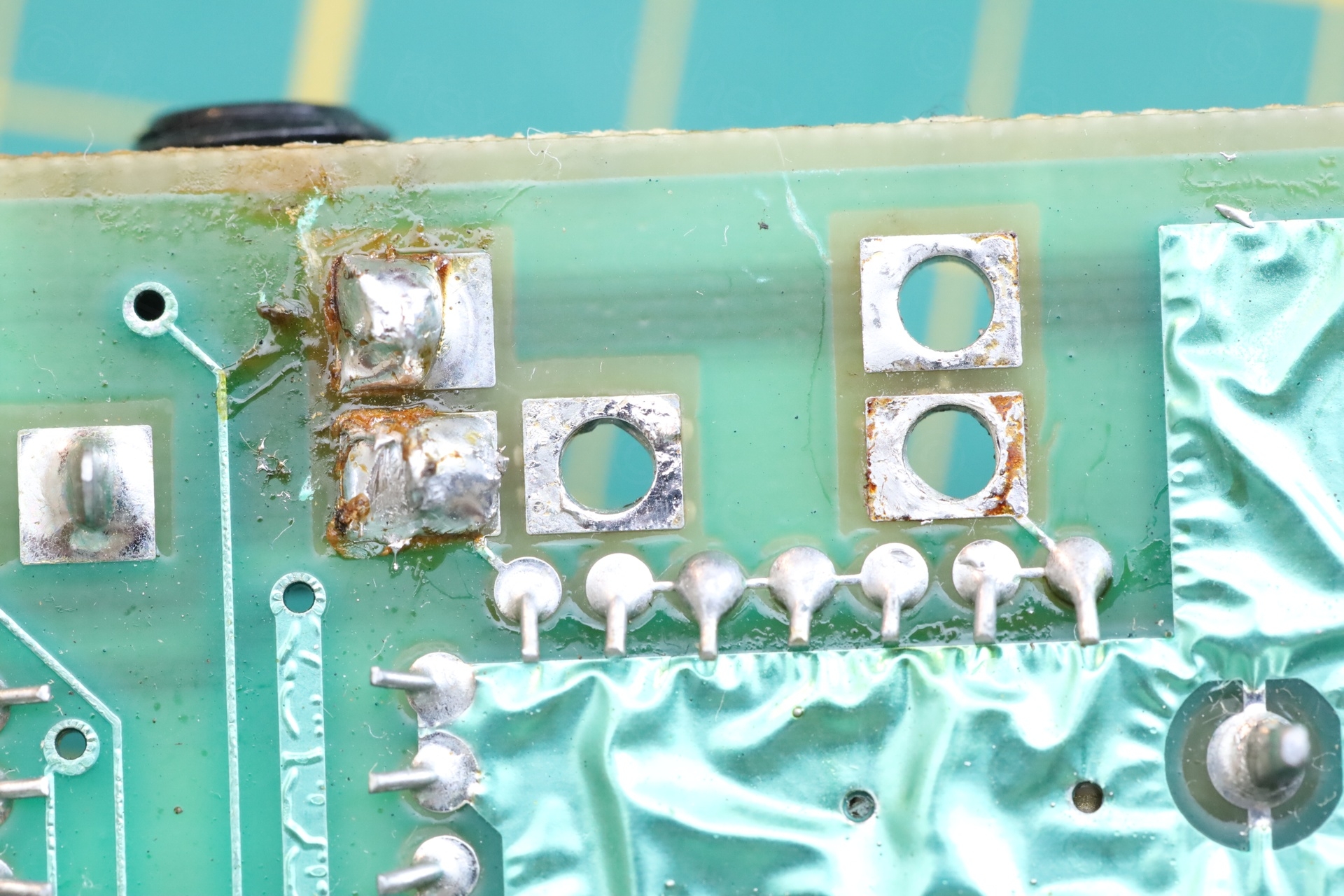
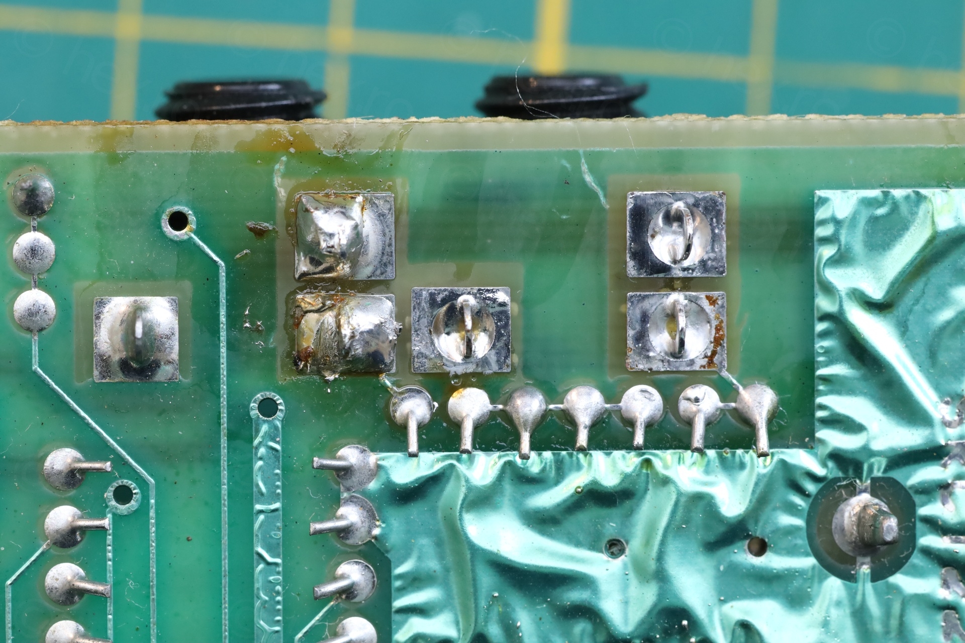
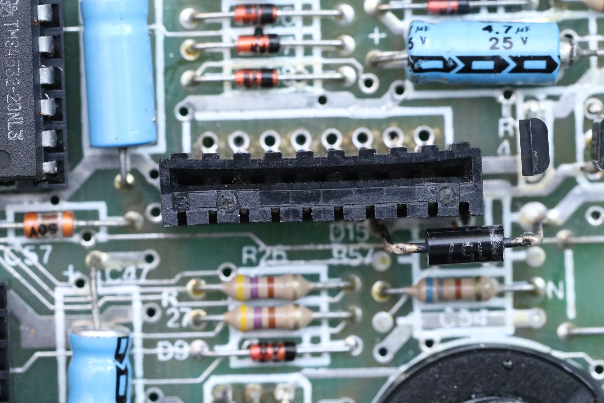
Keyboard connectors
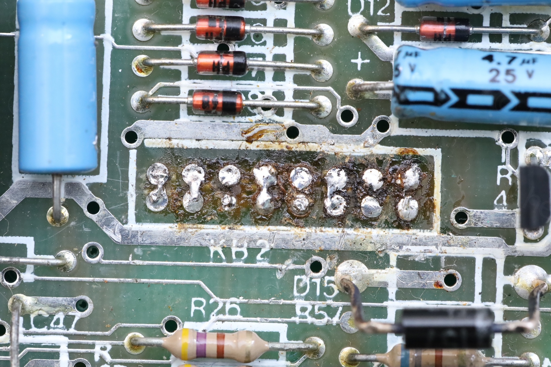
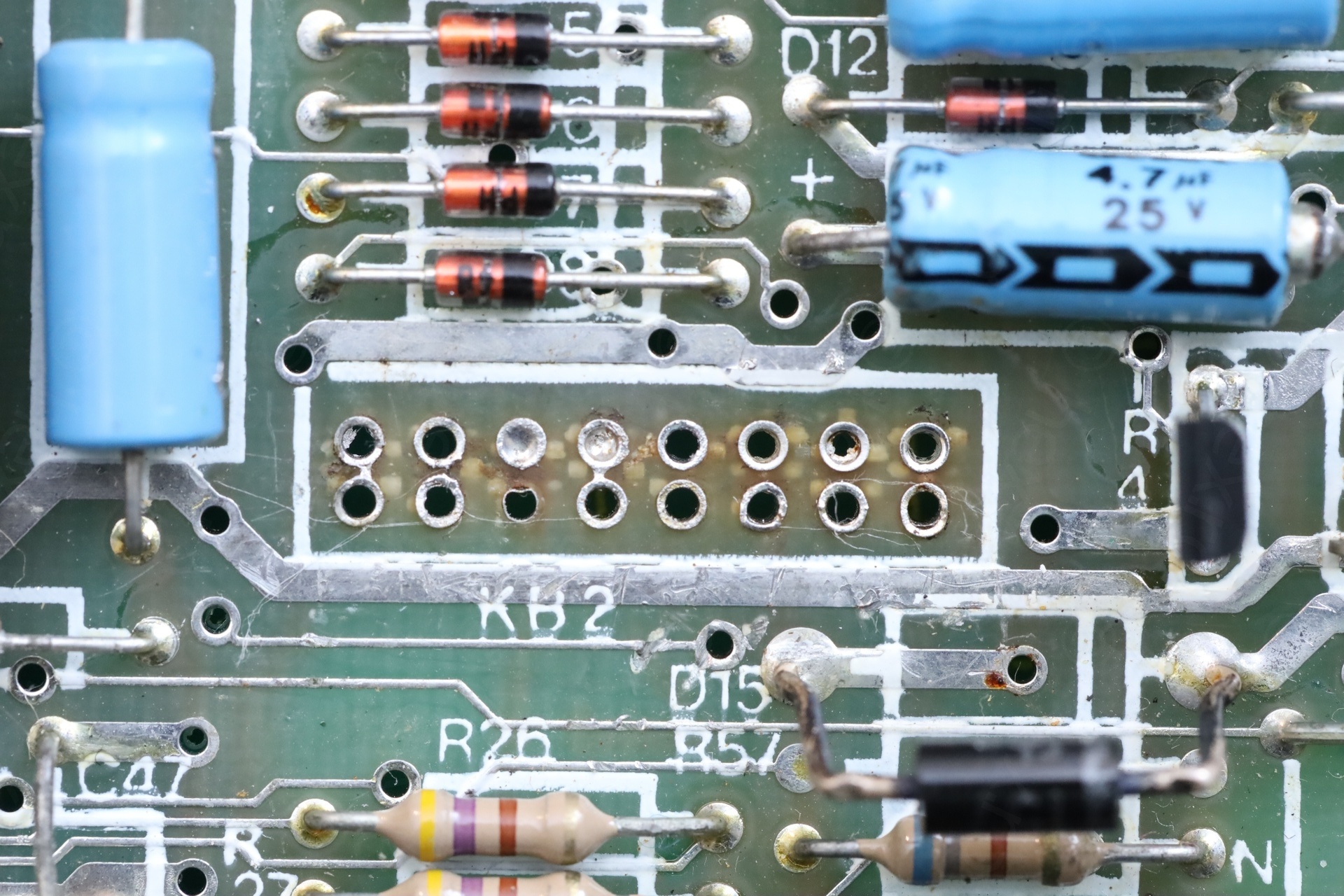
Before deciding what to do with the connectors, I first desoldered the ribbon cables and cleaned up the motherboard. Unfortunately, one of the pads was already lifted by whomever worked here first:
I found EU sellers that I could buy the connectors from, but expensive. They are sold cheap in UK, but then you have to pay some import and a minimum 15euros handling fee to the BPost.
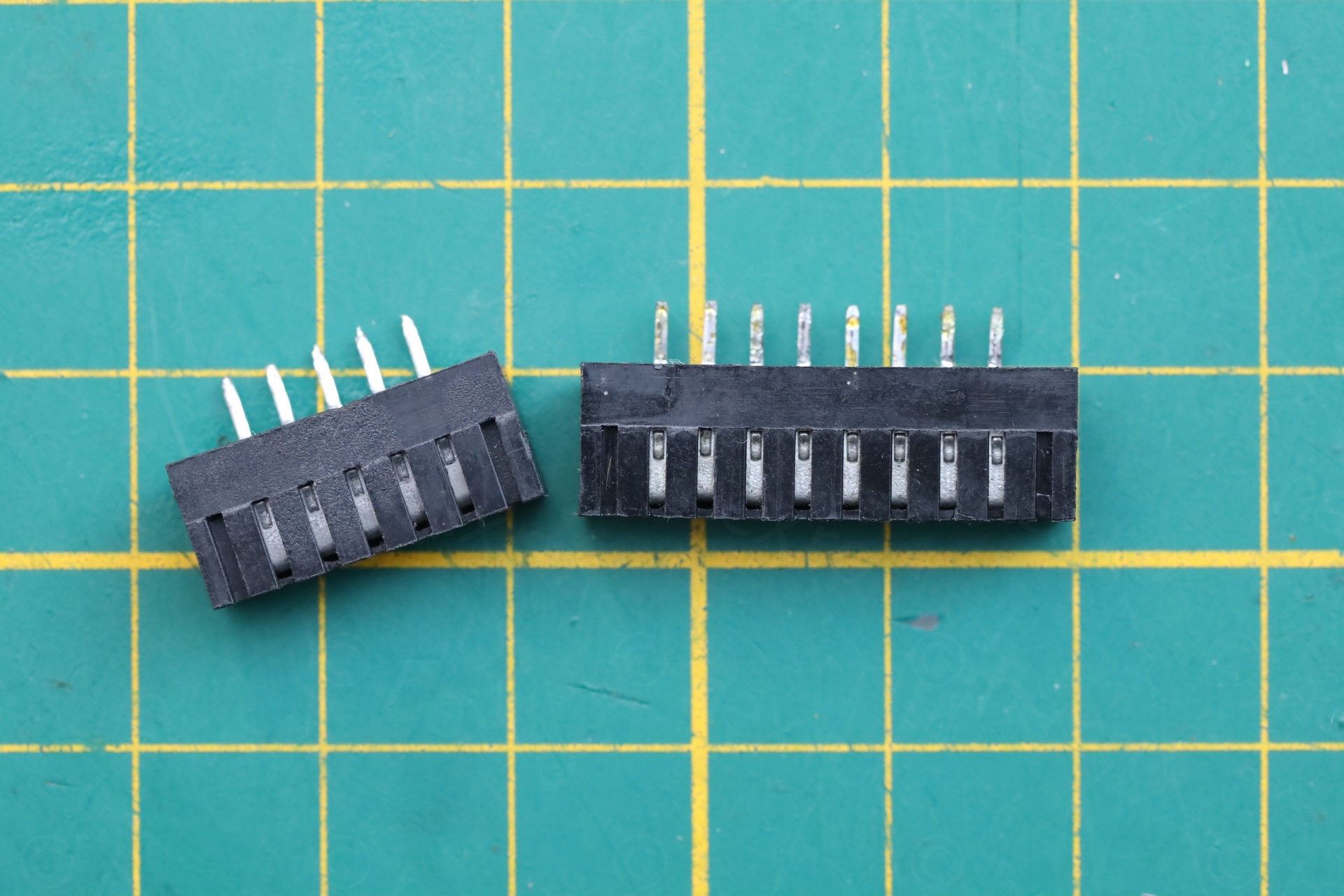
Was curious what exactly are these connectors, and through a Facebook post of people discussing possible replacements, I found these connectors on TME.eu:
DS1020-05ST1D | Connector: FFC/FPC; straight; PIN: 5; Non-ZIF; THT; tinned; 20mΩ
DS1020-08ST1D | Connector: FFC/FPC; straight; PIN: 8; Non-ZIF; THT; tinned; 20mΩ
However, before ordering, I ended up just plundering a donor board I had lying around. And payed attention to install them the right way round:
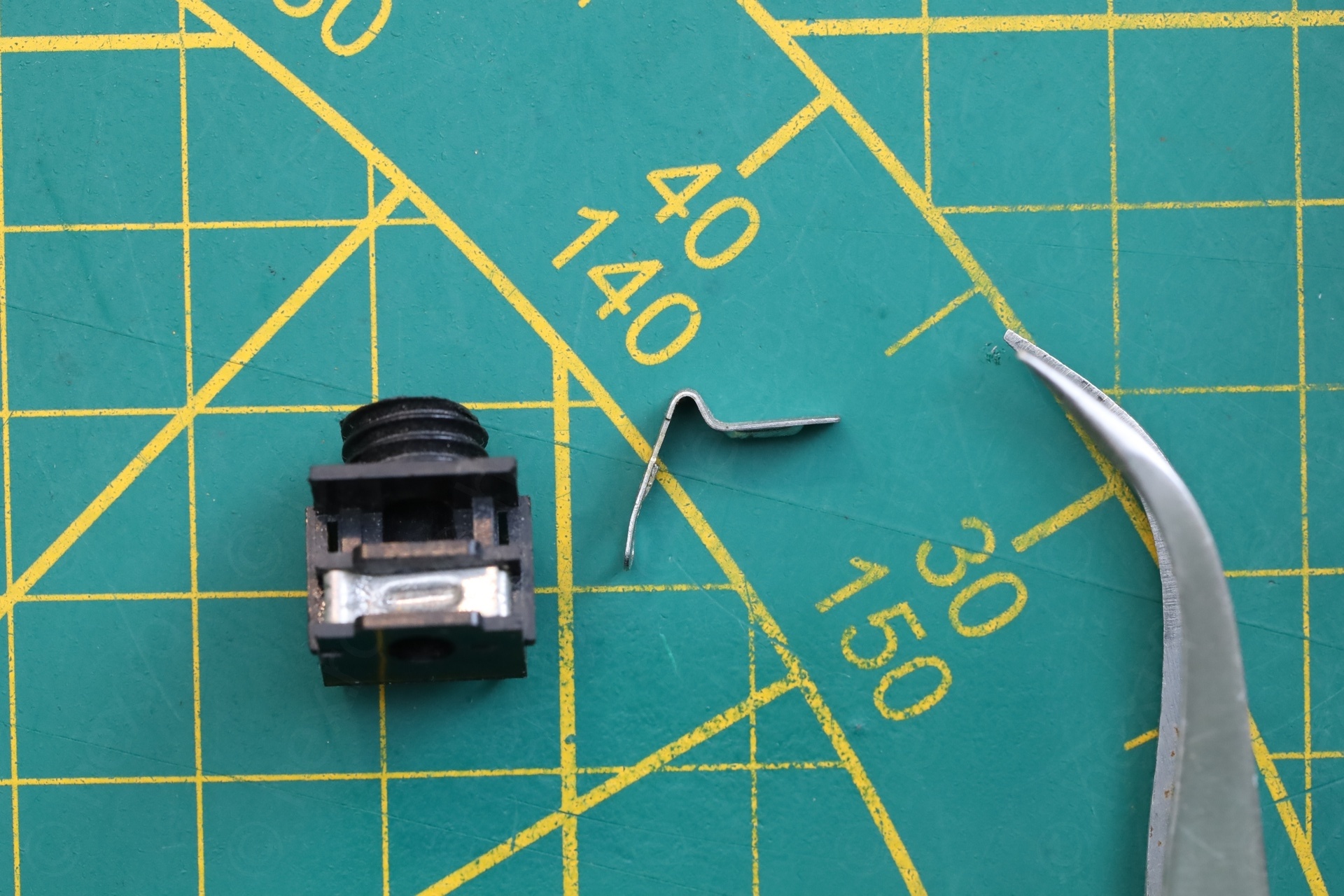
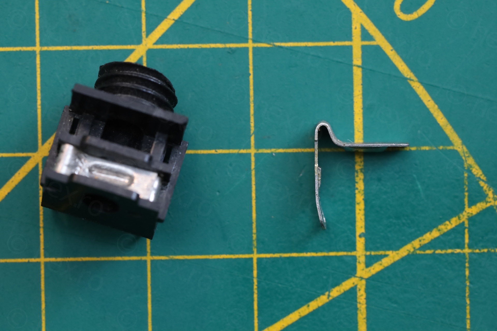
DC Power Jack
The DC Power Jack was very fiddly, just a touch and it would loose contact. I installed a replacement. The amount of heat required is tremendous … but I did manage.
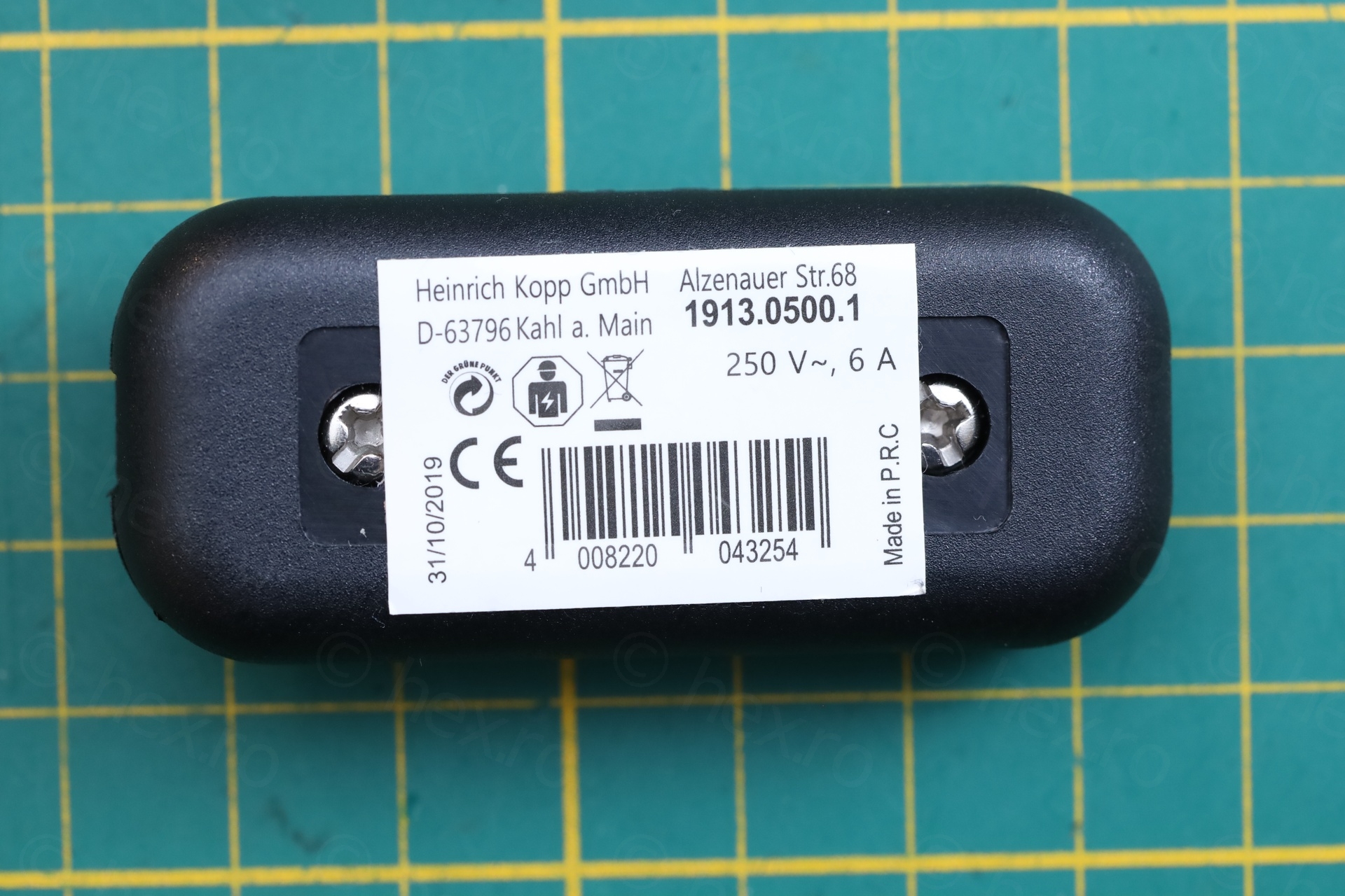
Power supply
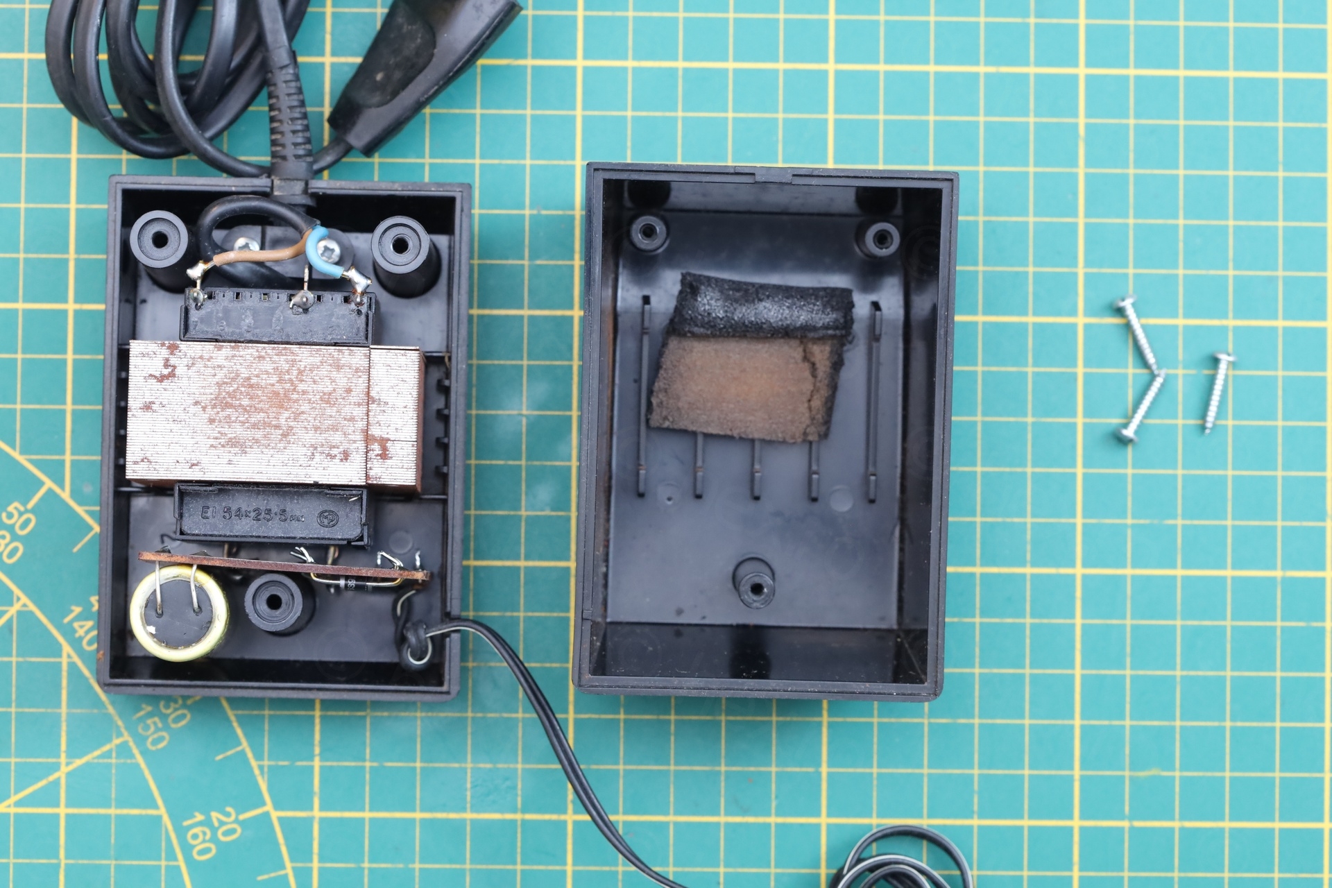
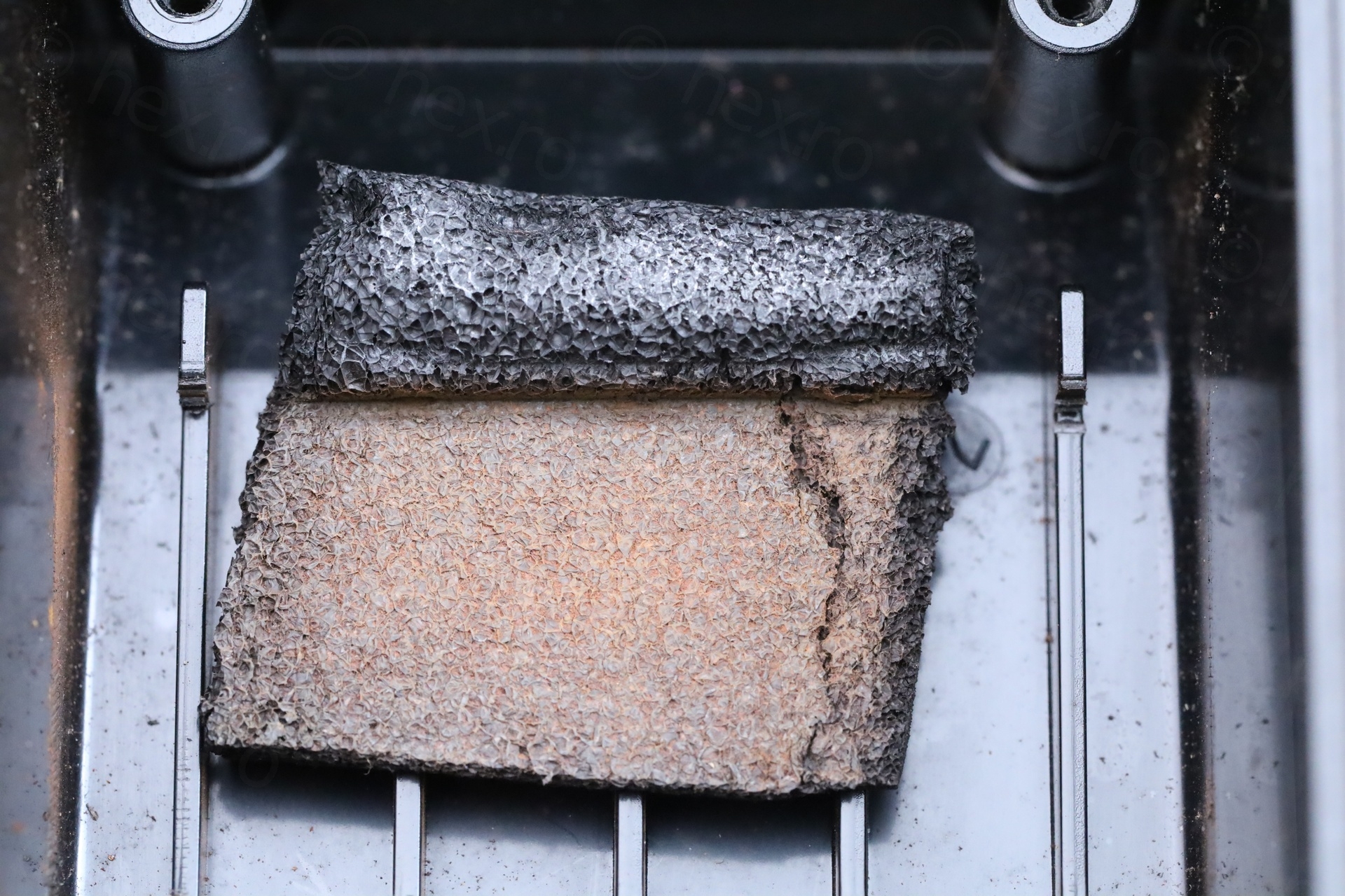
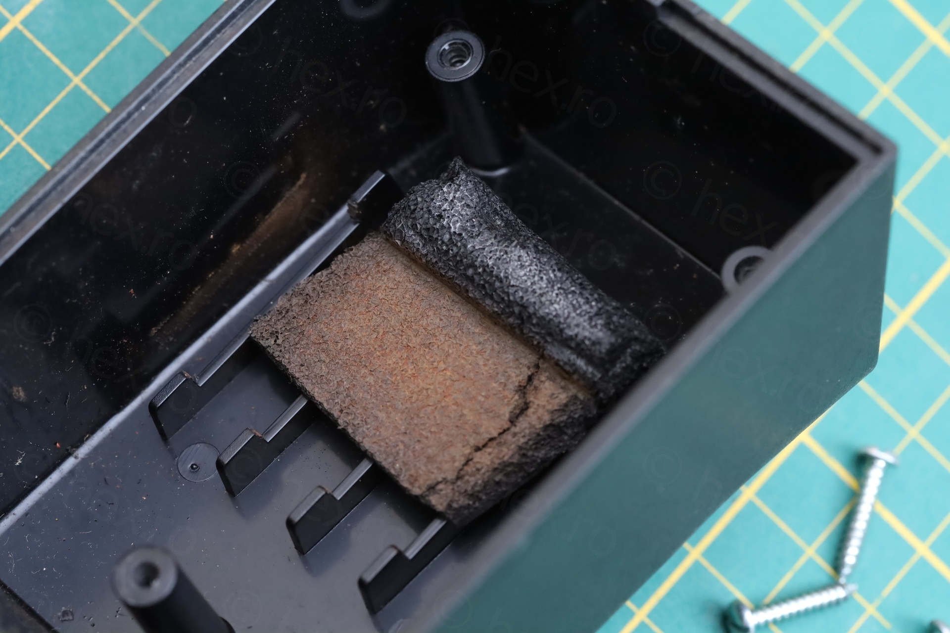
After so many improvisations, the power supply made my eye brow rise. What would lie there within ?! The transformer was rattling inside, feeling loose – and the inline ON/OFF button was not bouncing back properly.
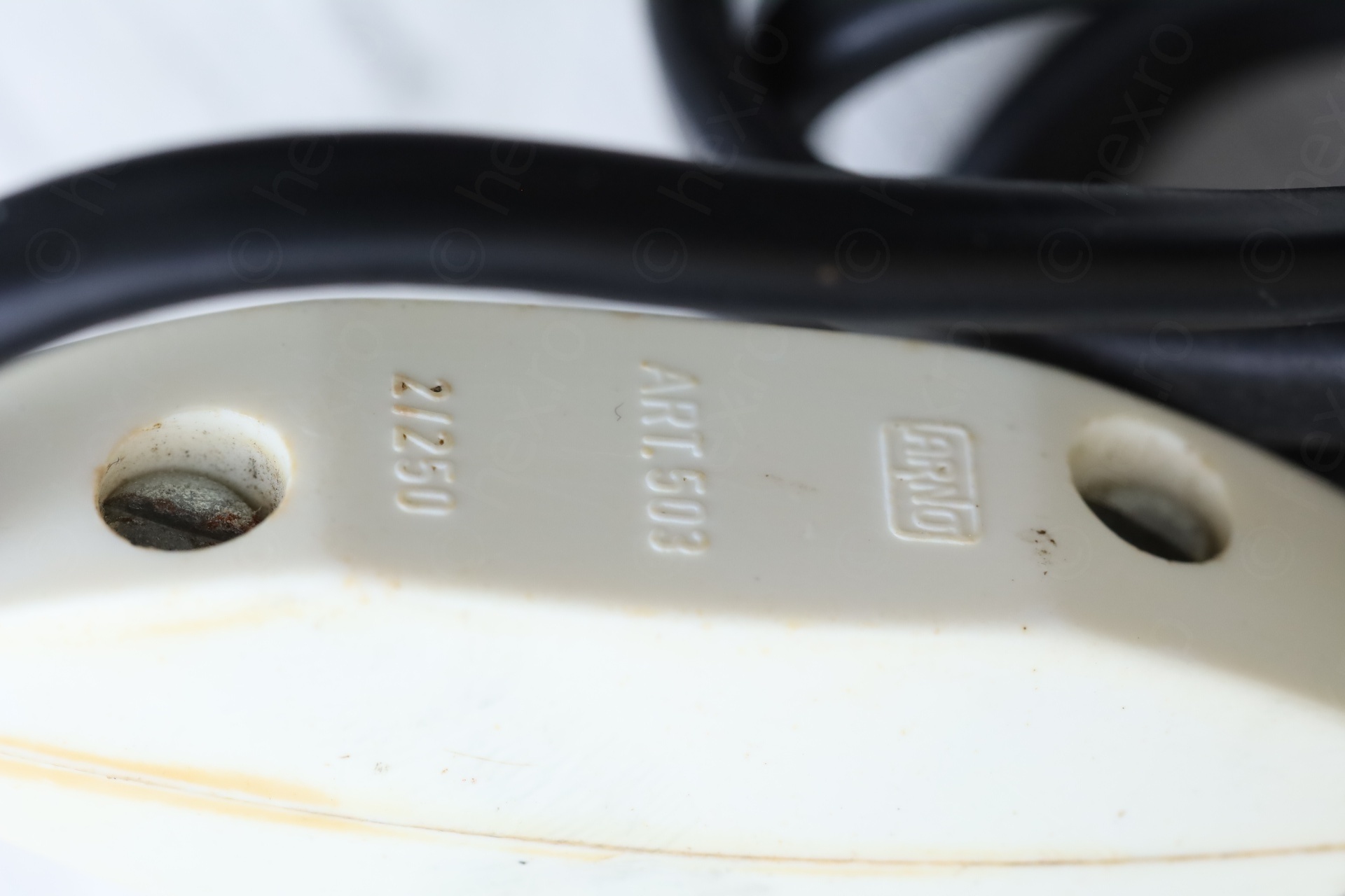
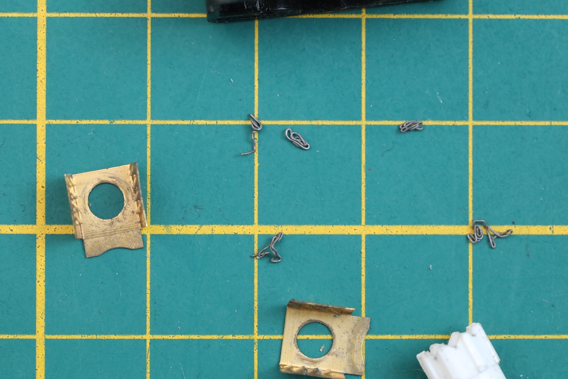
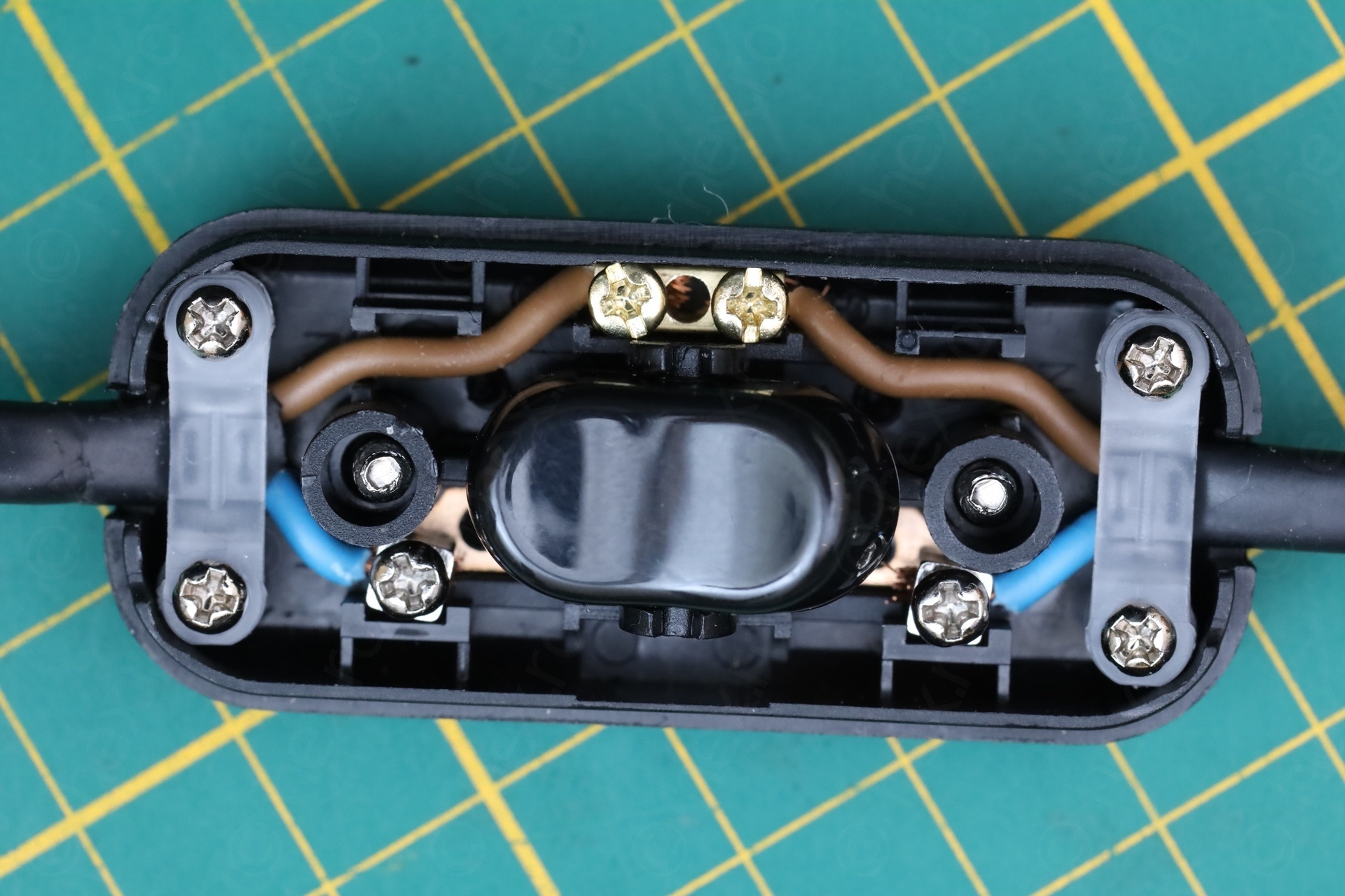
The ON / OFF switch was an old school one, without cable clamps. The wires were kept in by some tiny plastic pegs. Copper strands broke free in time and were jamming the switch – a prime example why cable clamps are mandatory for safety:
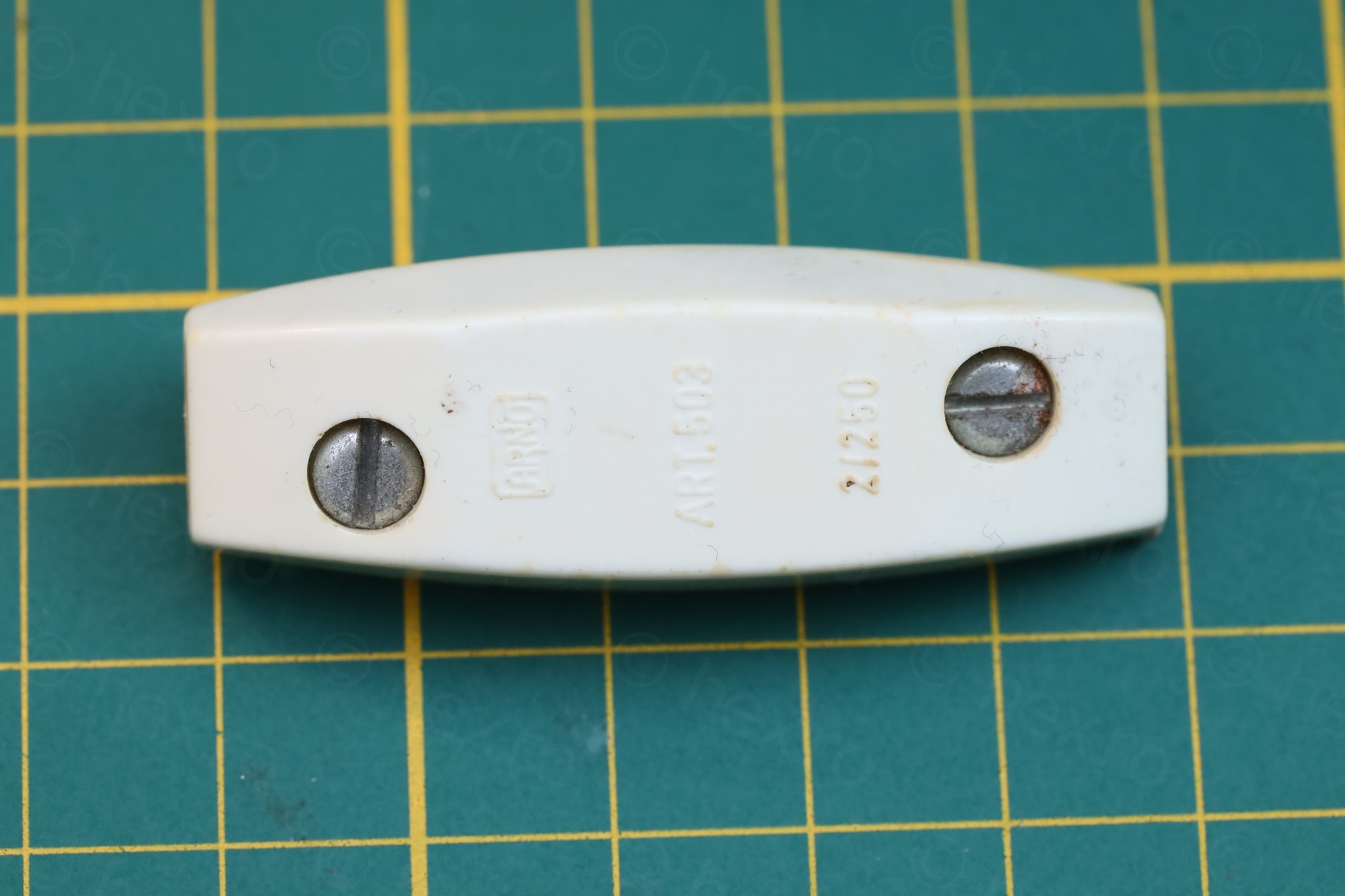
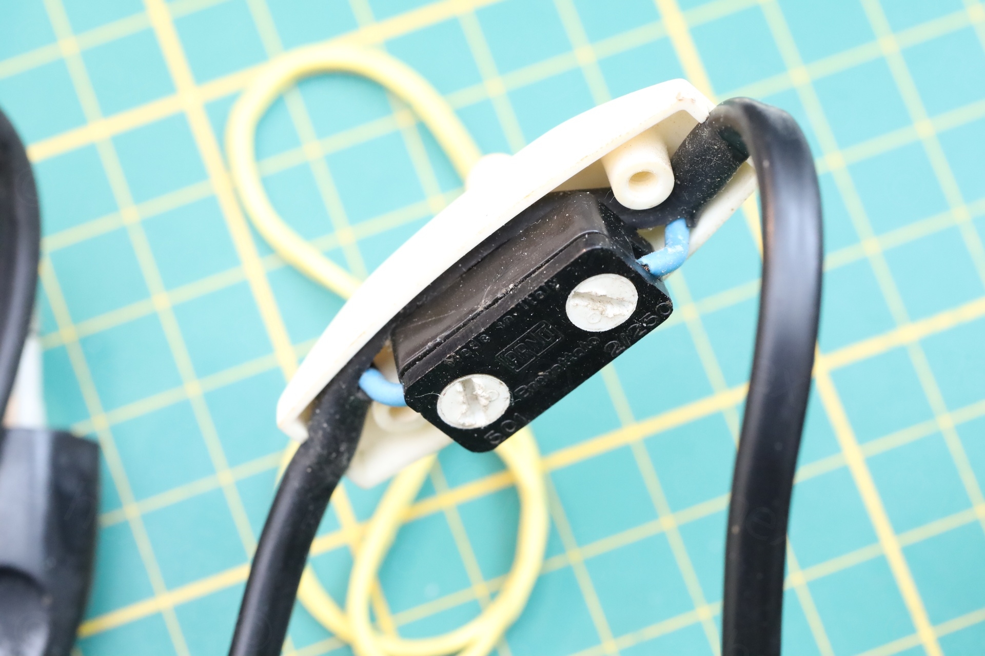
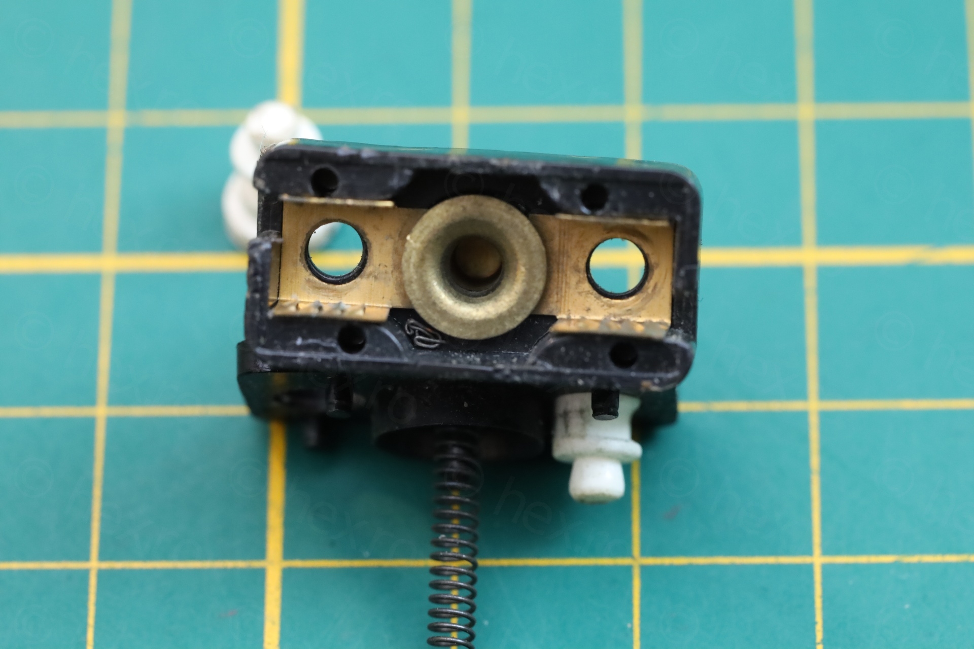
I decided to replace the switch with a new one with cable clamps:
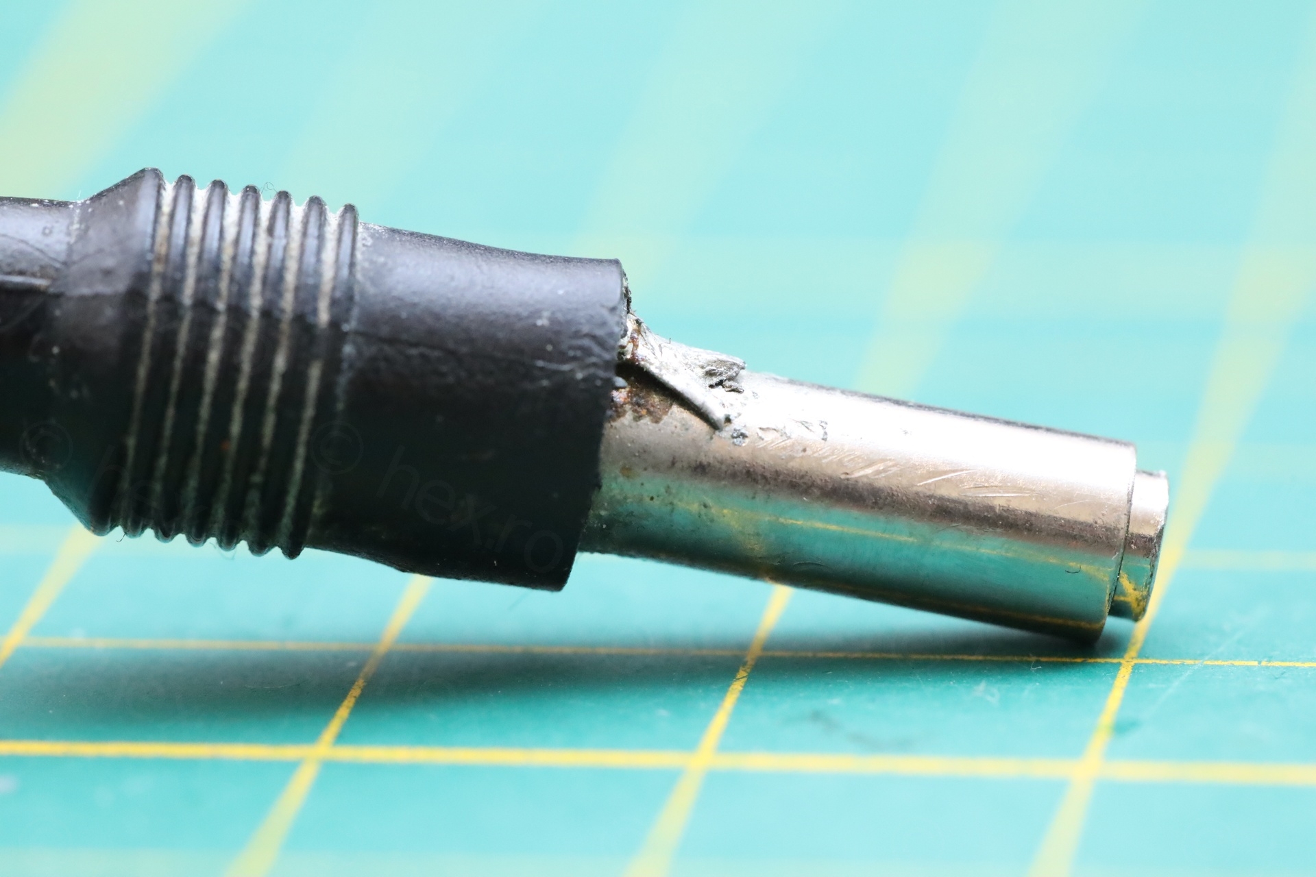
The power supply also go ta new DC jack – due to the soldering I saw on the barrel.
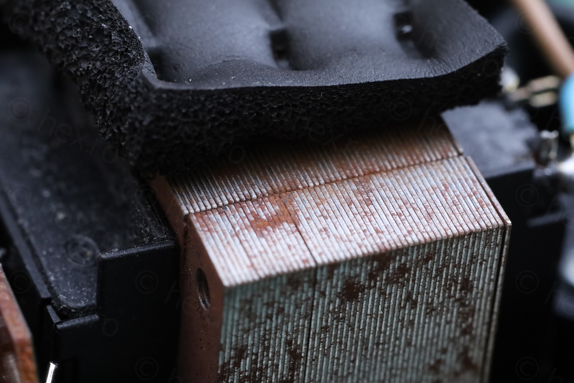
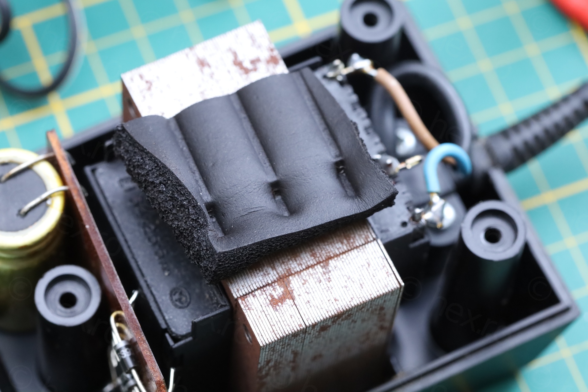
I almost forgot to write about the rattling inside. It was due to the foam being so squished in time – that it lost its “pressing” power. I was thinking to replace it with some neoprene – but eventually, I just rotated it with 90 degrees, there was still enough to keep some pressure. And keep more of the original:
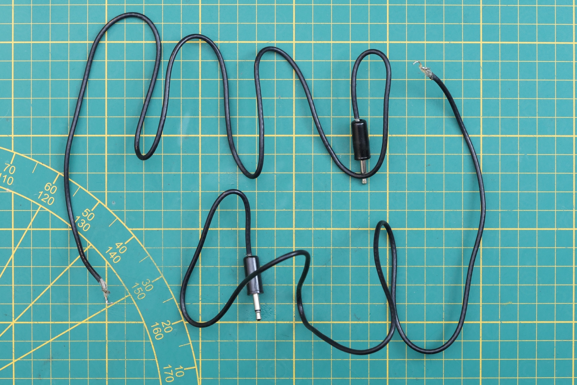
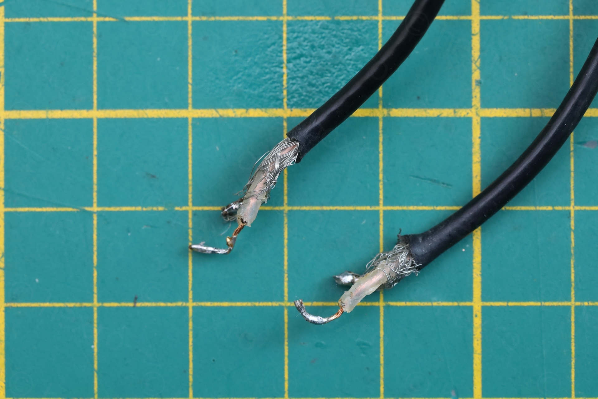
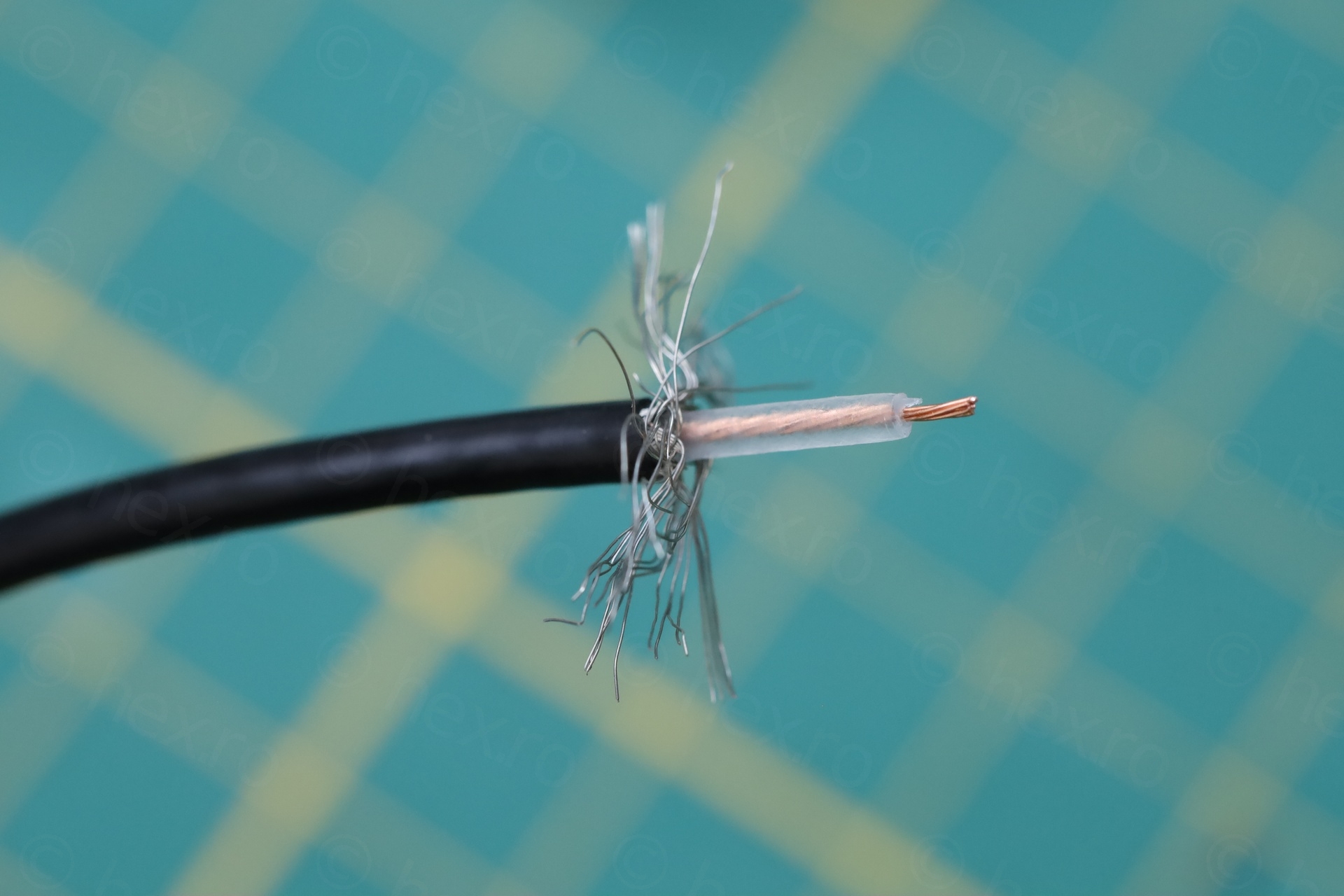
Audio cable – Reunited
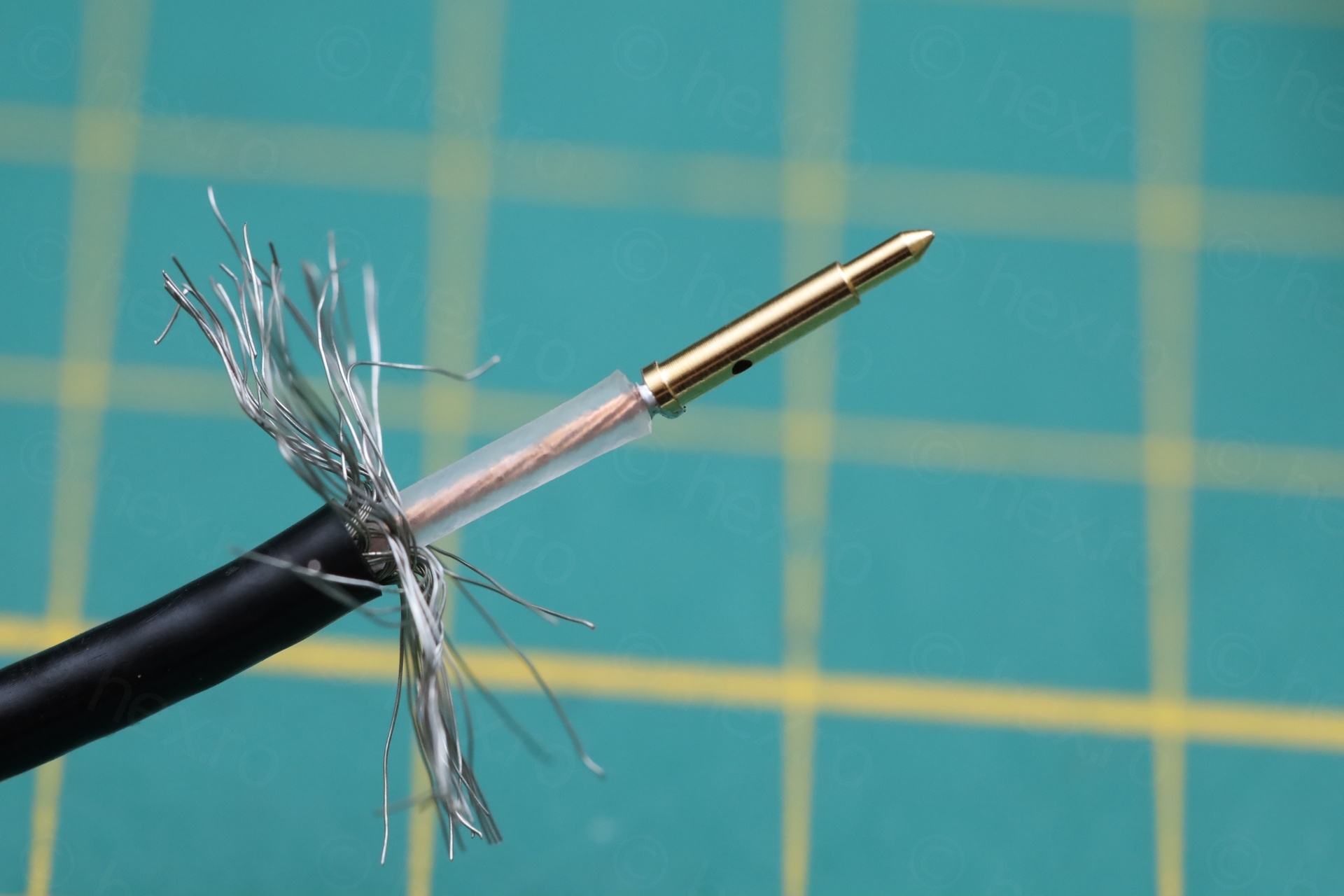
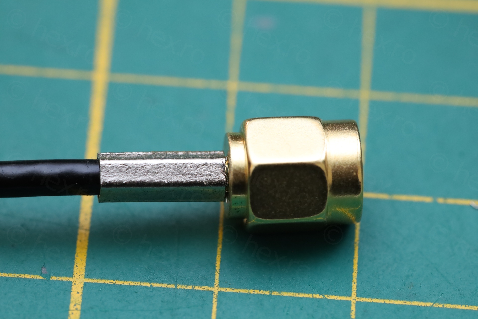
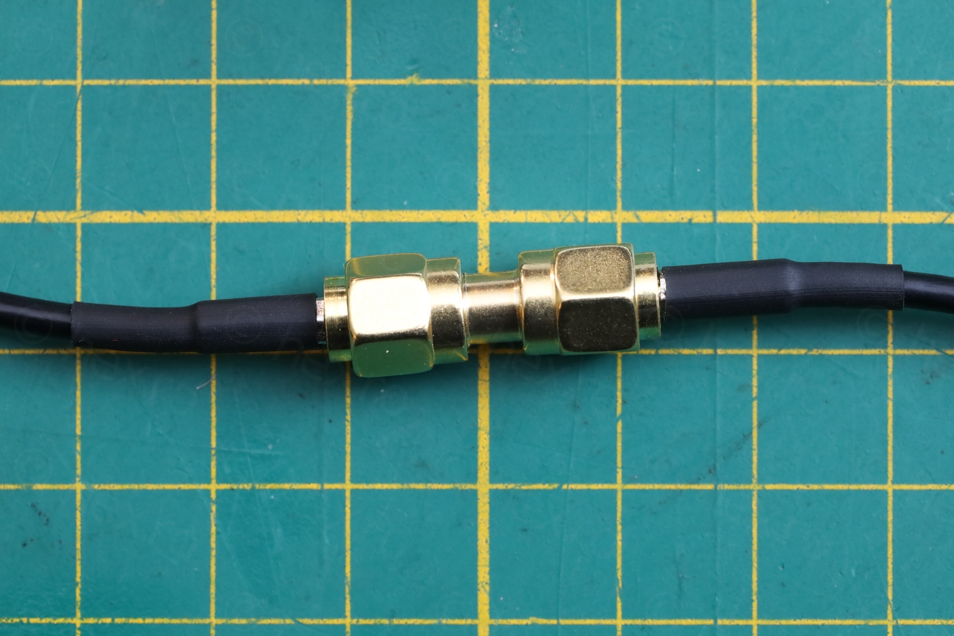
The motherboard had some audio cables directly soldered to it. I de-soldered them, but I realized those cables were in fact the two halves of an initial one. But I couldn’t just solder it back, felt bad for a coaxial cable. I decided to do it better, and here I am waiting for just one more order, this time for RG316 SMA connectors.
I didn’t crimp the center pin, just soldered it. For audio, it should be good. Another drawback in that now the ground of the circuit is exposed, and sometimes I have too many wires around.
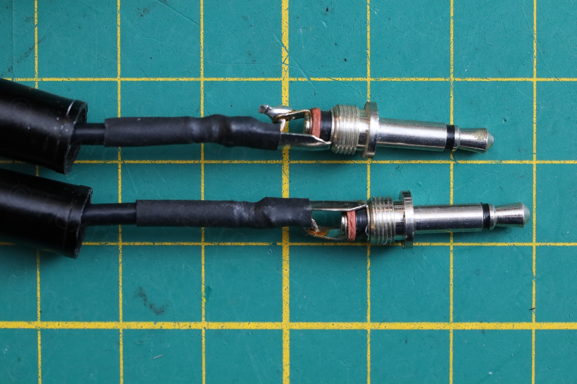
Also took care of isolating the mono jacks to give them a bit more strength and safety.
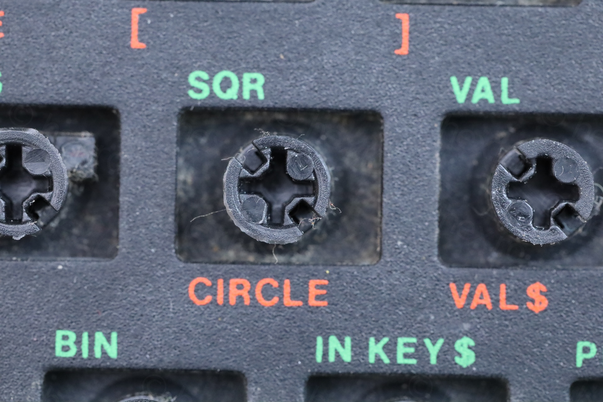
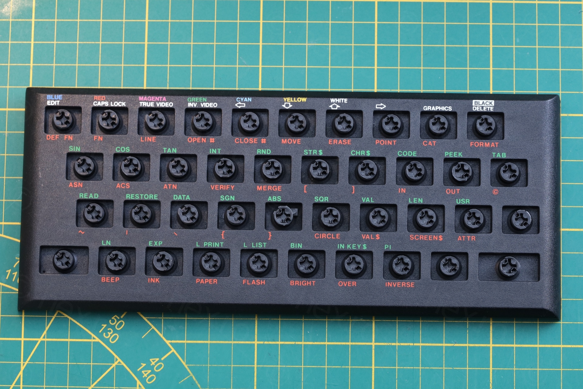
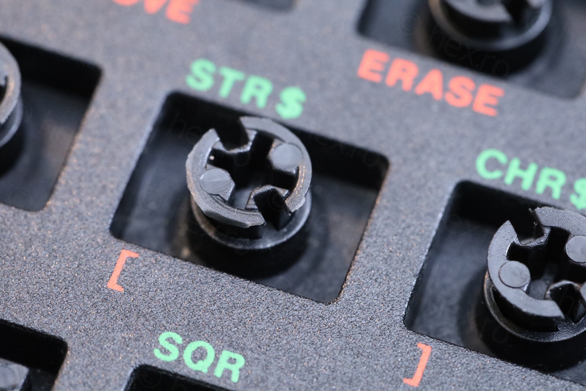
Teclado mecánico
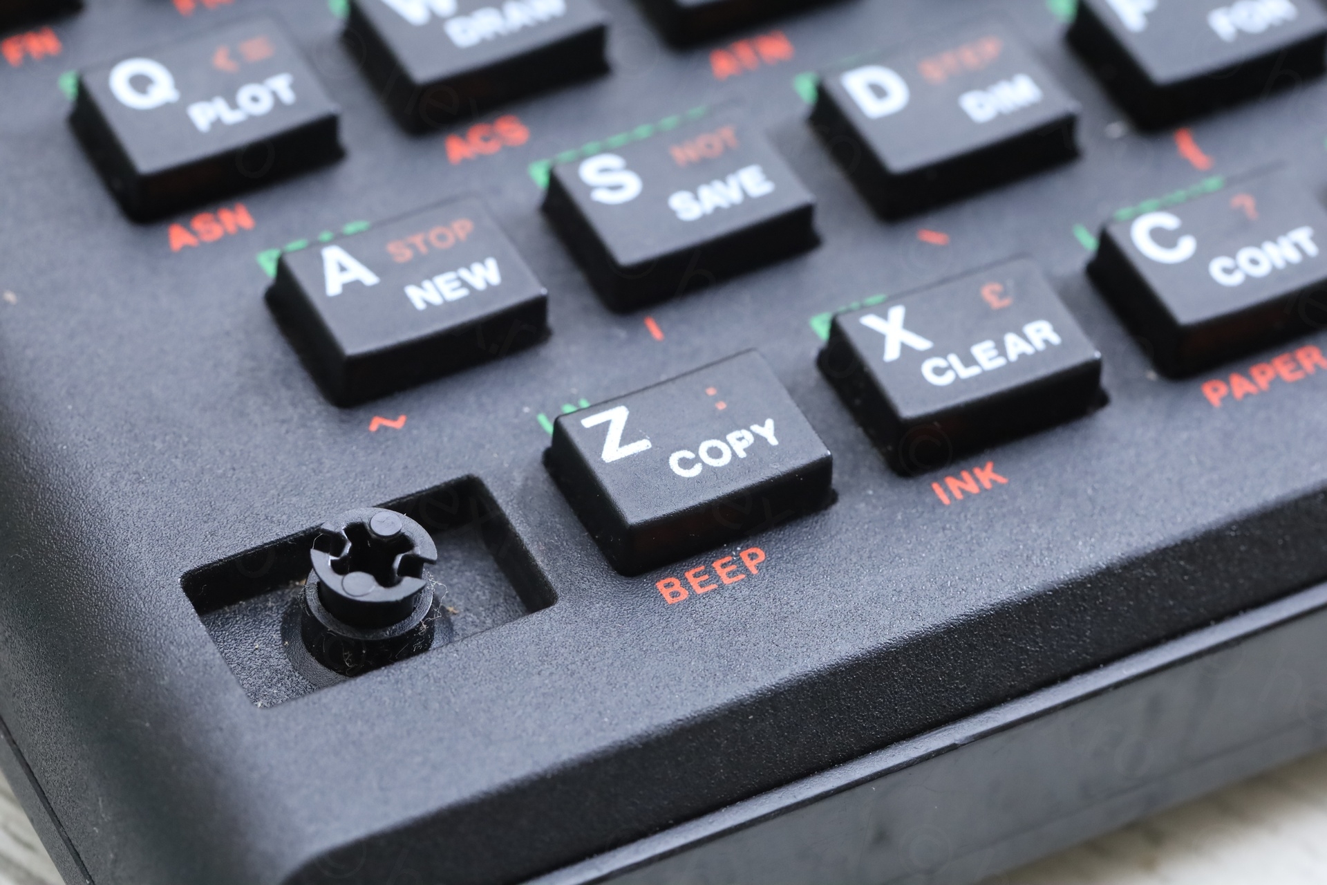
This keyboard posed some problems getting it to work as best as it can. From coming up with a solution for the missing CAPS button, to figuring out why some of the existing buttons get stuck when pushed. Finally to the screws that were too short (or their screw hole enlarged with time, and they could not bite enough onto).
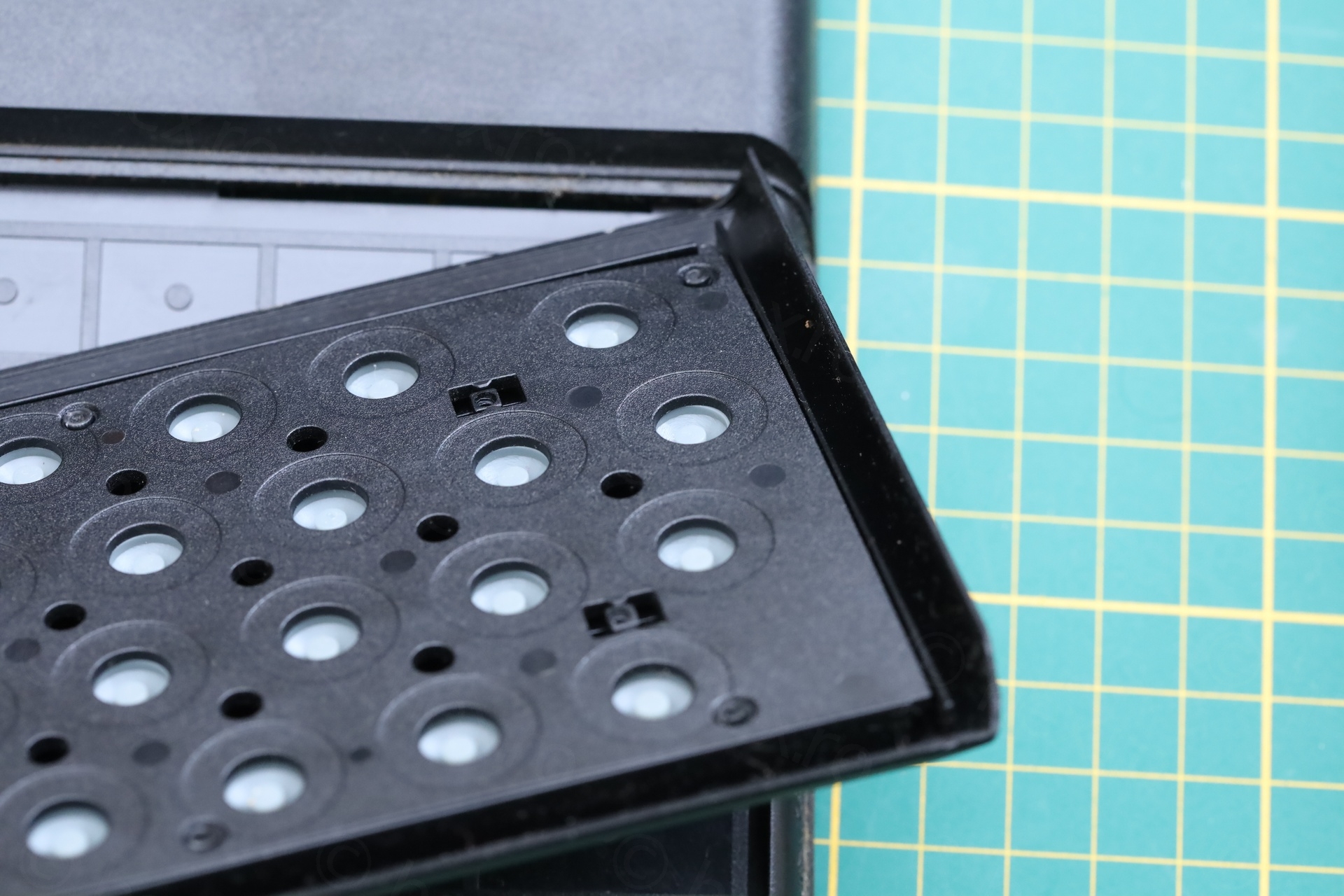
Cleanup
Although they keyboard itself was not looking dirty, there was still some cleanup to do.
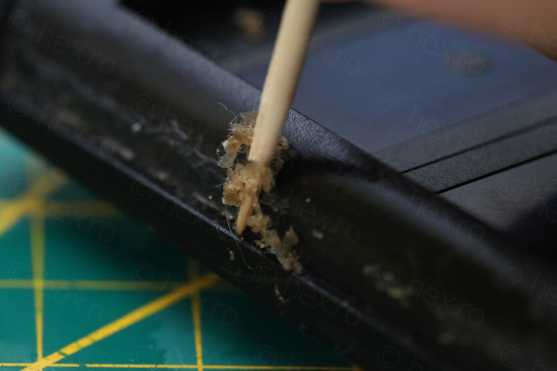
First, removing the remains from the sticky glue used to hold they keyboard down:

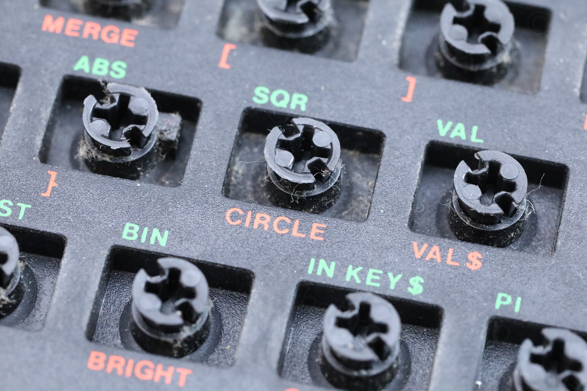
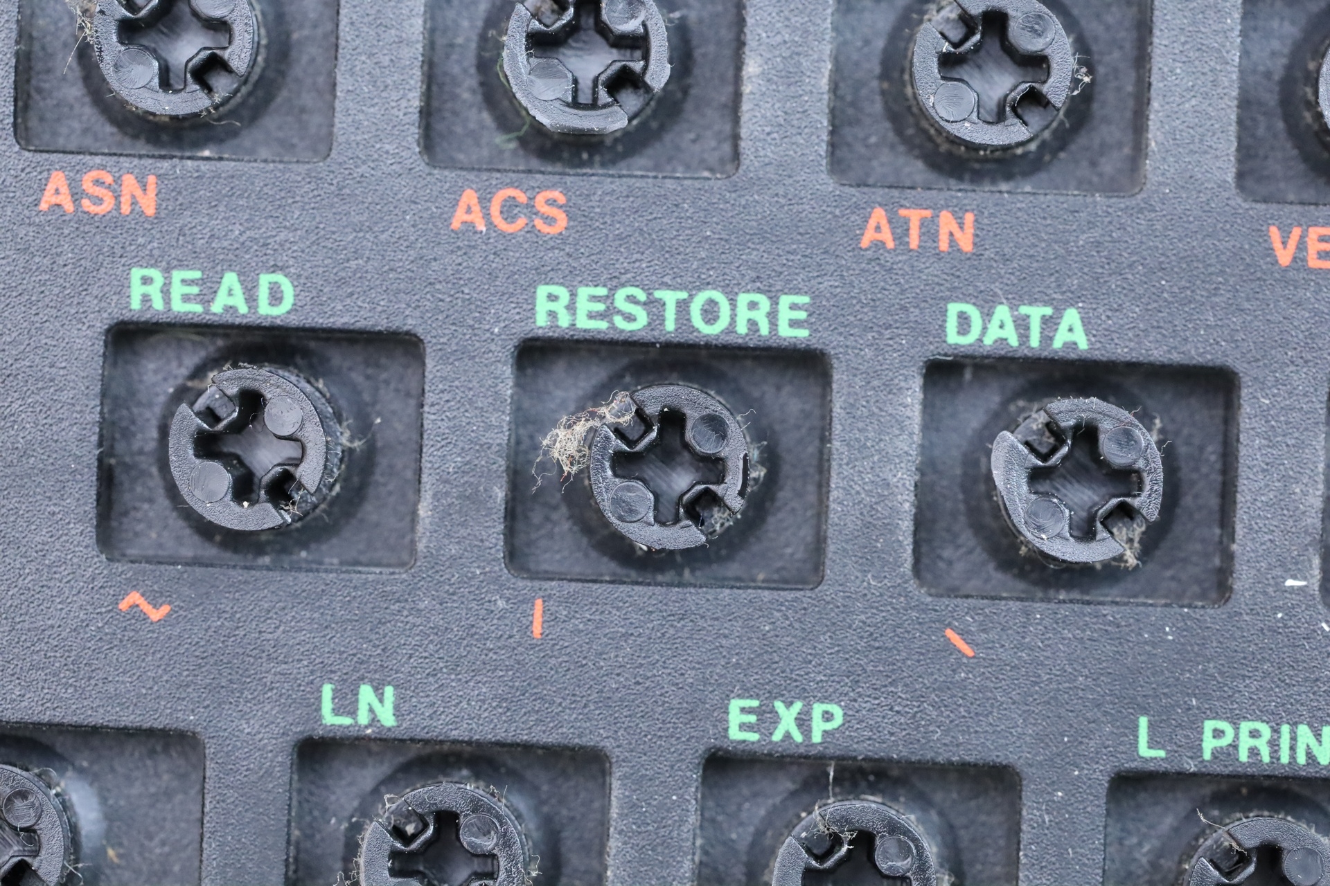
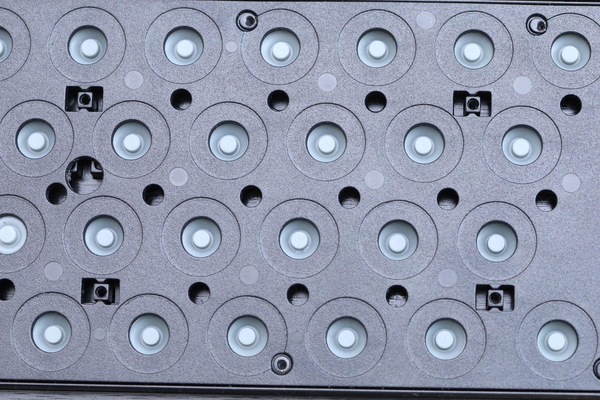
Second, I removed all the buttons, to inspect them. Some of them were getting stuck when pushed down, not bouncing back. Photos from the dismantling and de-dusting:
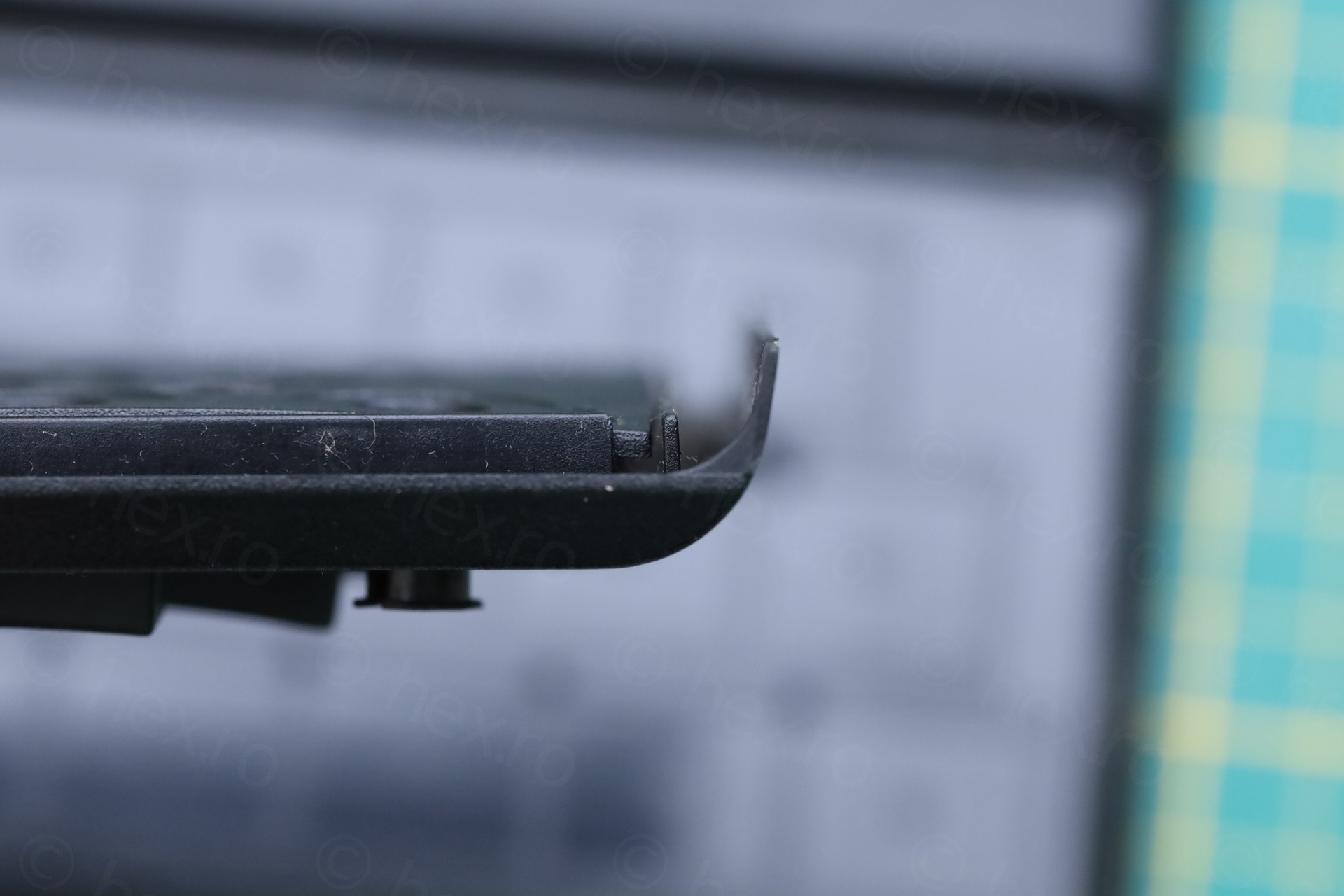
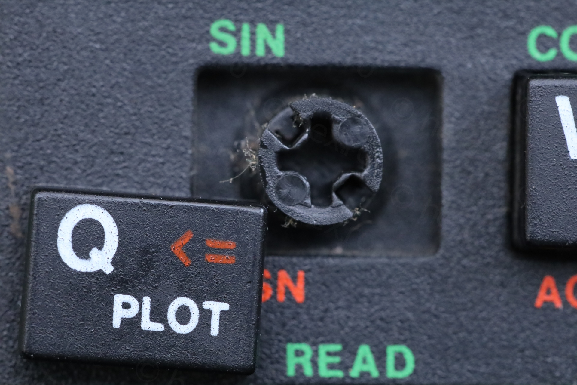
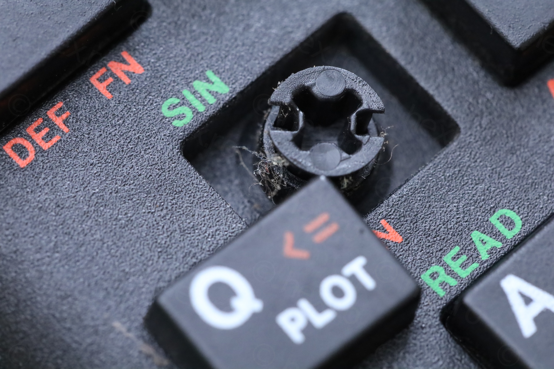
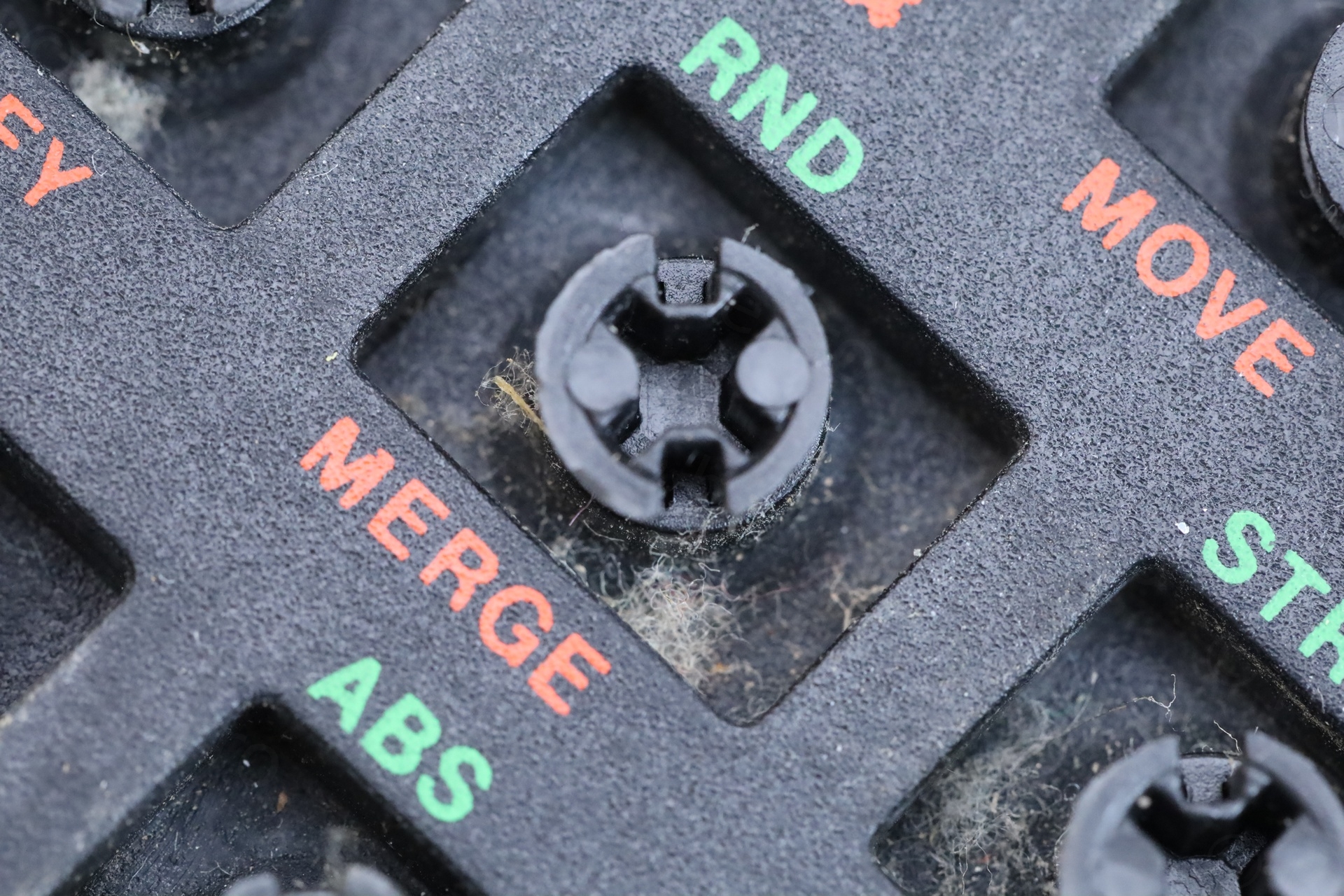
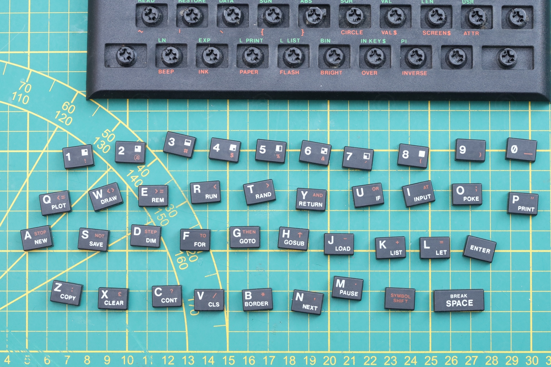
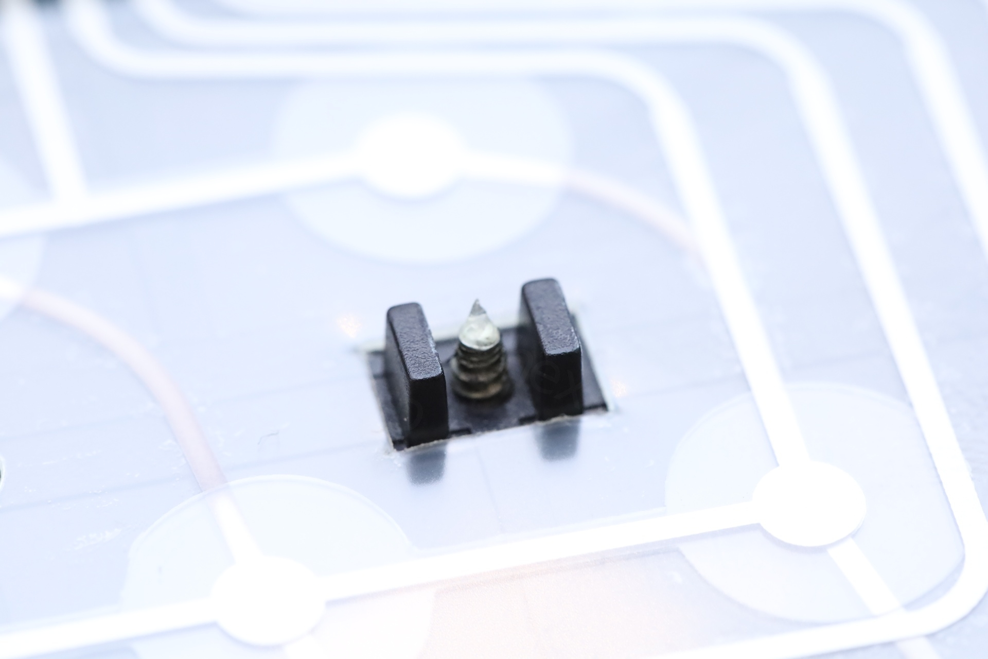
I thought a lot why the buttons would stick. Pushing down on the center post was easy. It was only with the plastic key cap that they were getting stuck with. Because they were rather wobbly and the key cap would jam itself into a corner. After some trial and error, I realized that its own rubber membrane must not go past a certain deformation, otherwise those buttons would just jam.
Eventually, I understood where the problem was. The body of the keyboard bowed upwards in time, allowing some buttons (especially towards the center, like the G or J) to travel downwards past the return point.
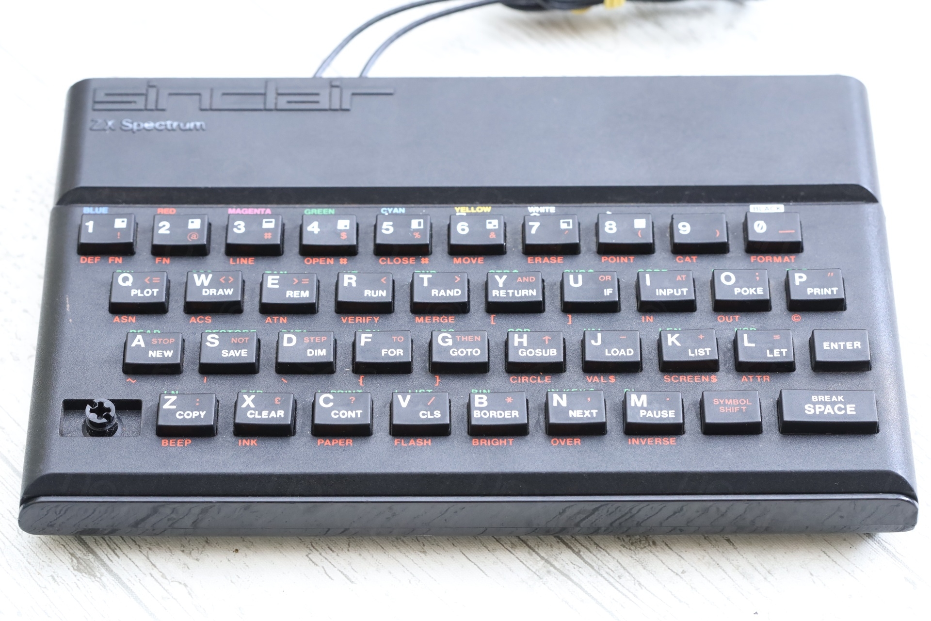
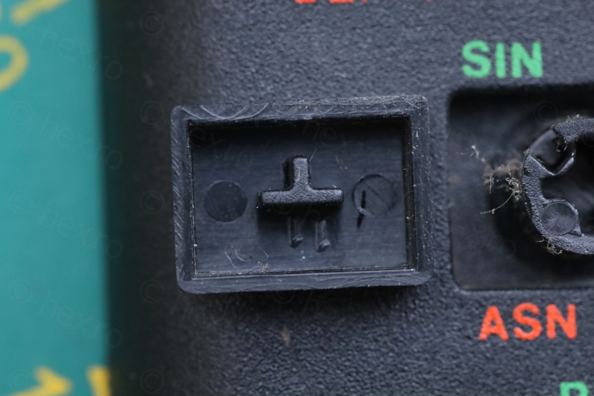
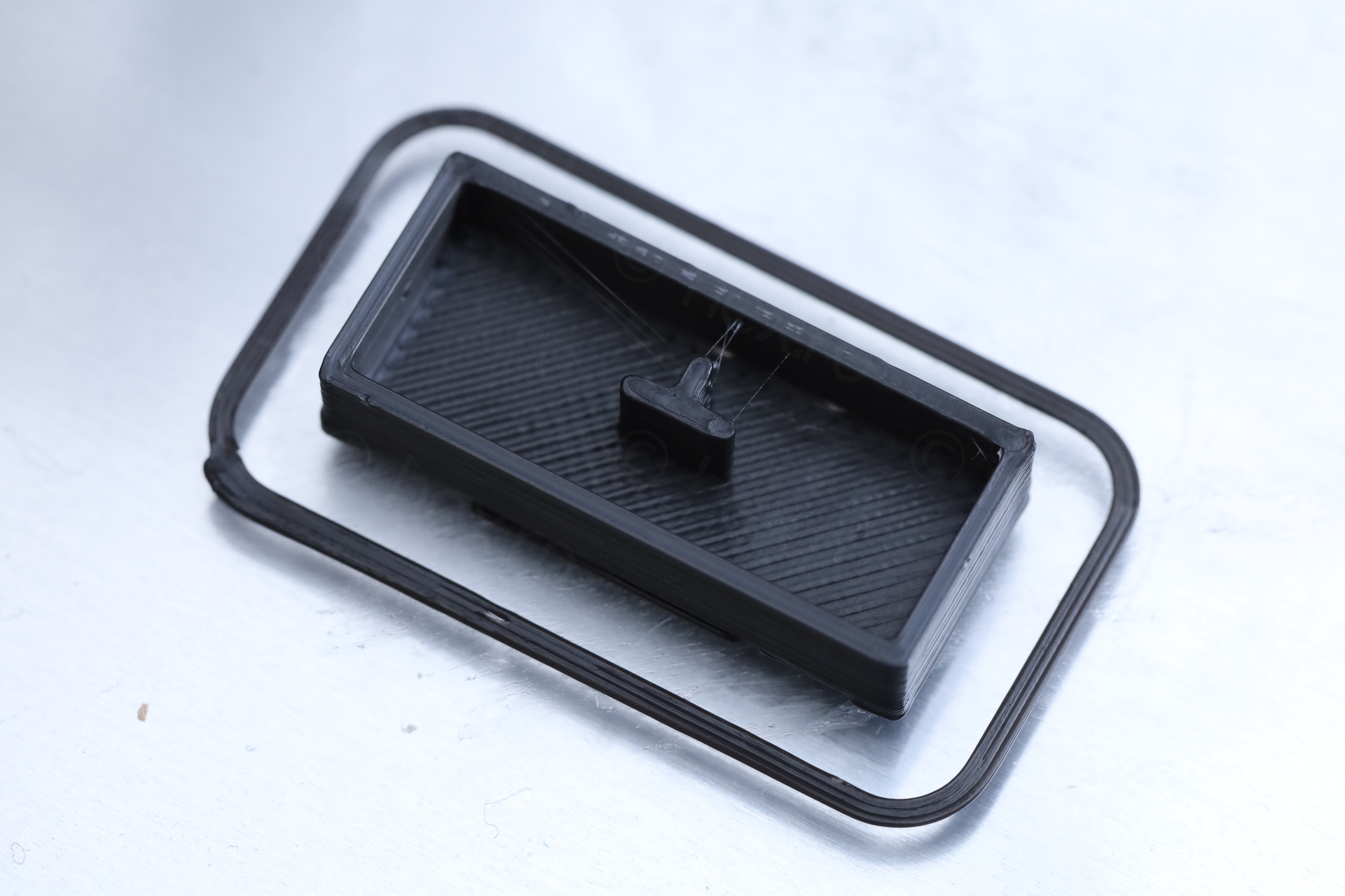
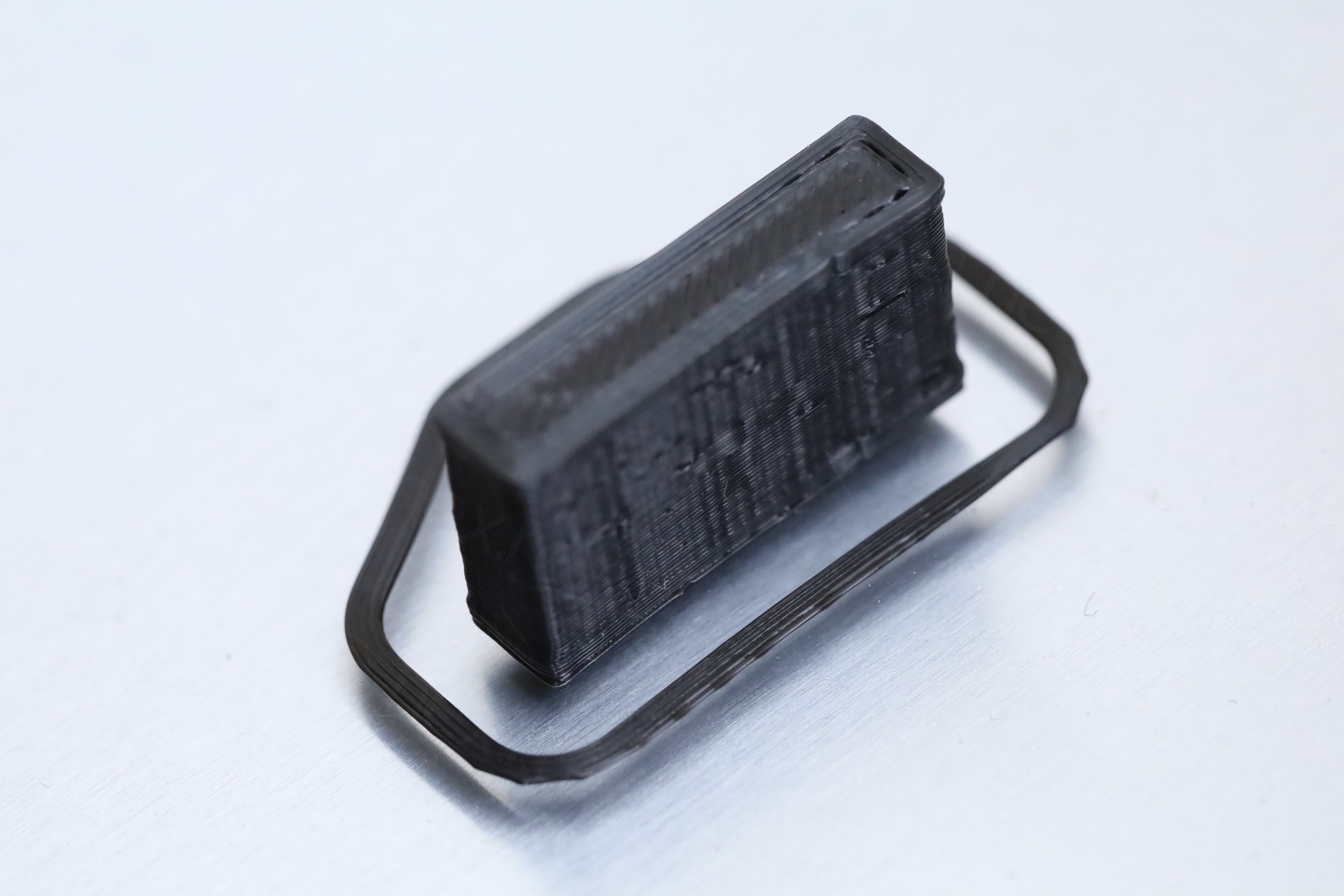
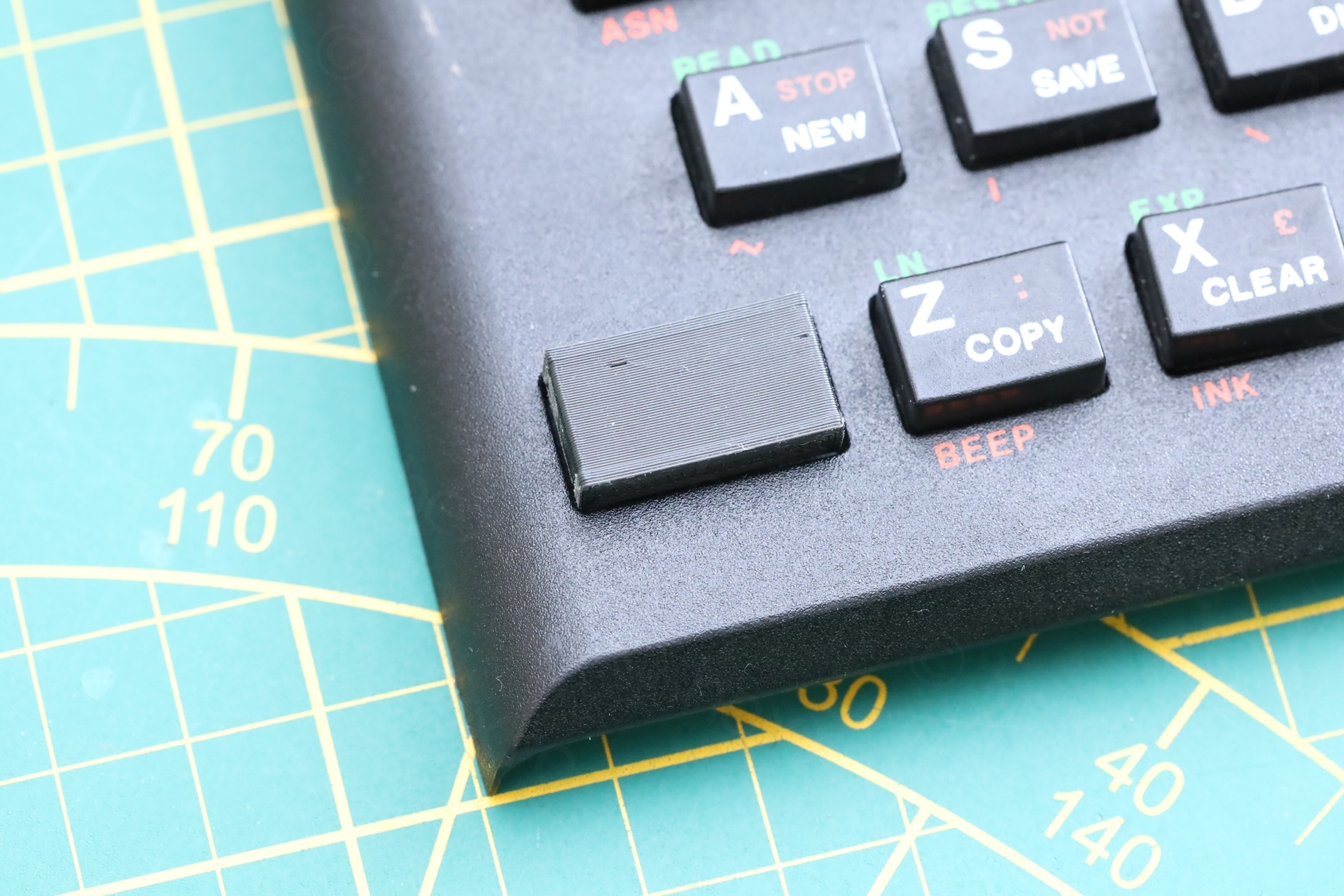
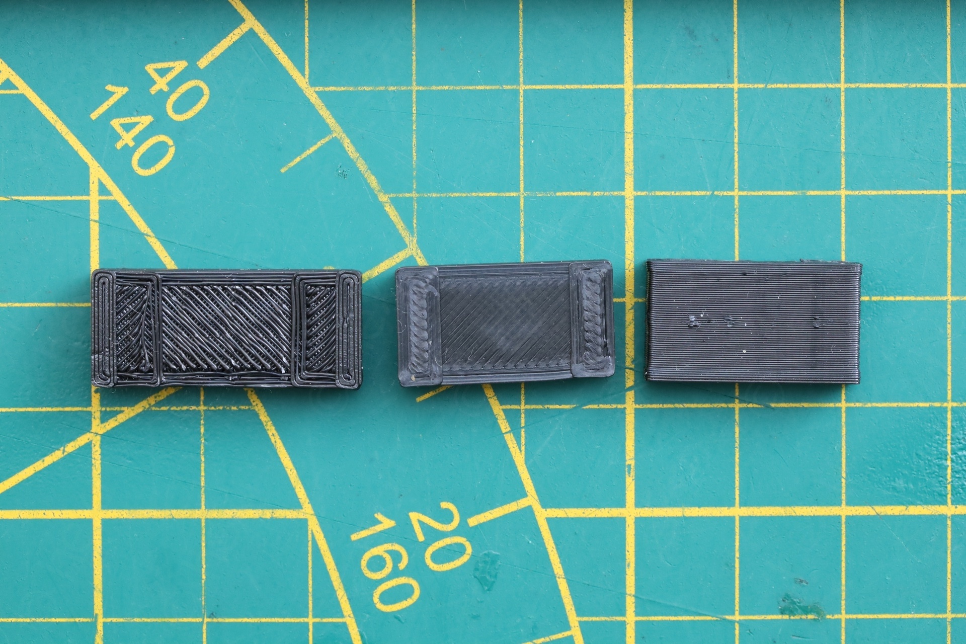
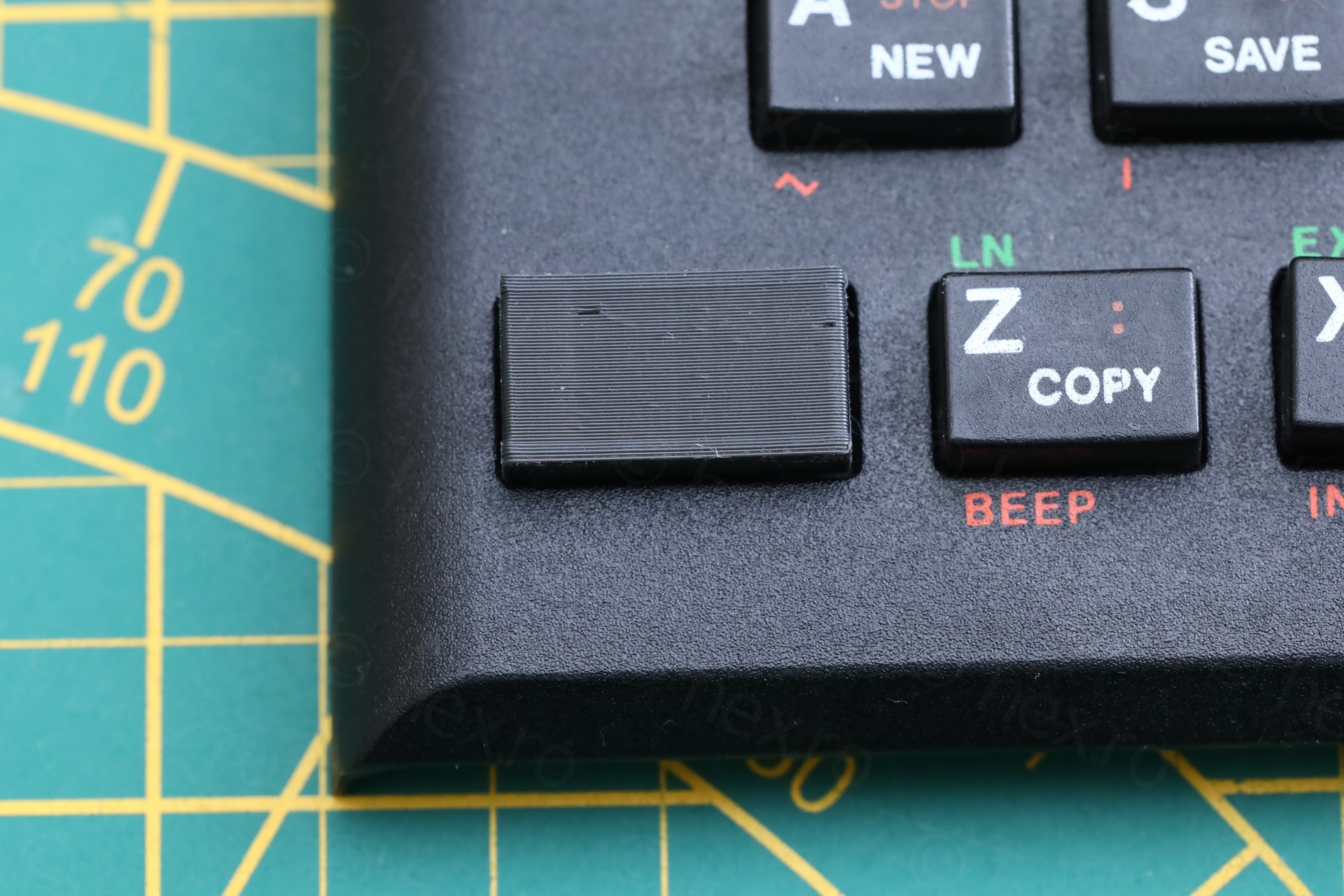
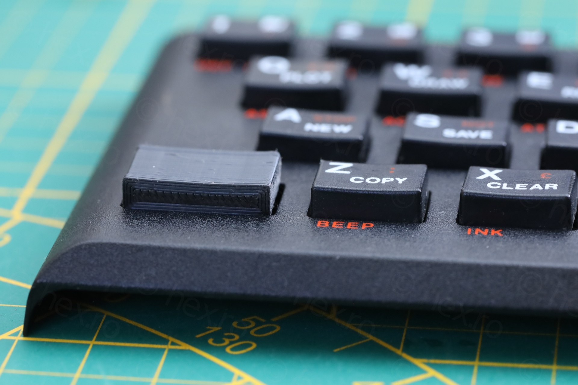
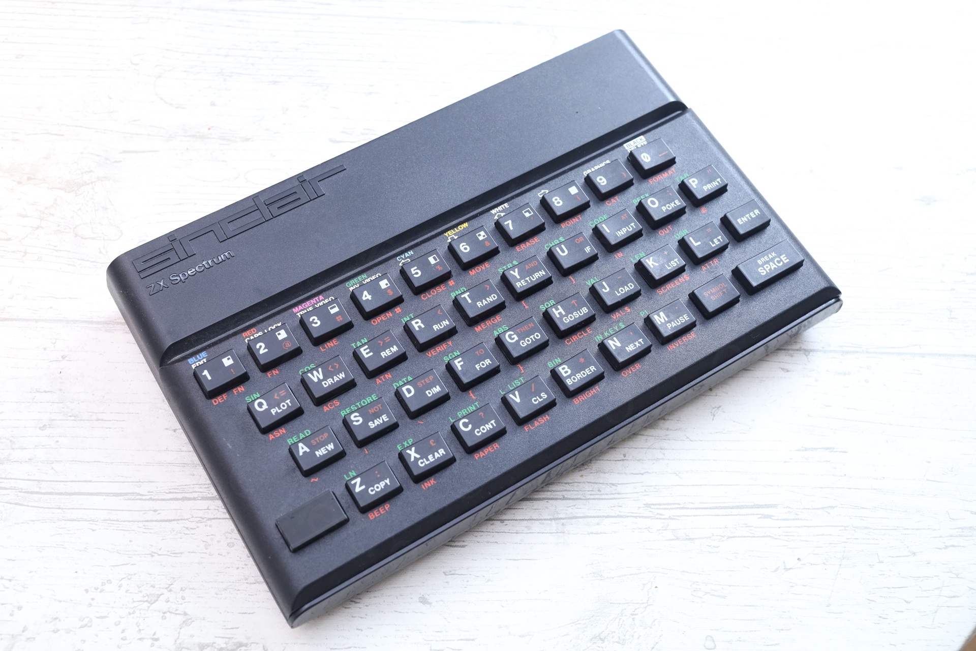
3D Printing the CAPS button
I decided to 3D print the missing CAPS button, since the design seemed pretty easy to duplicate. I had few trial runs, but ended up with a usable replacement:
Stuck buttons
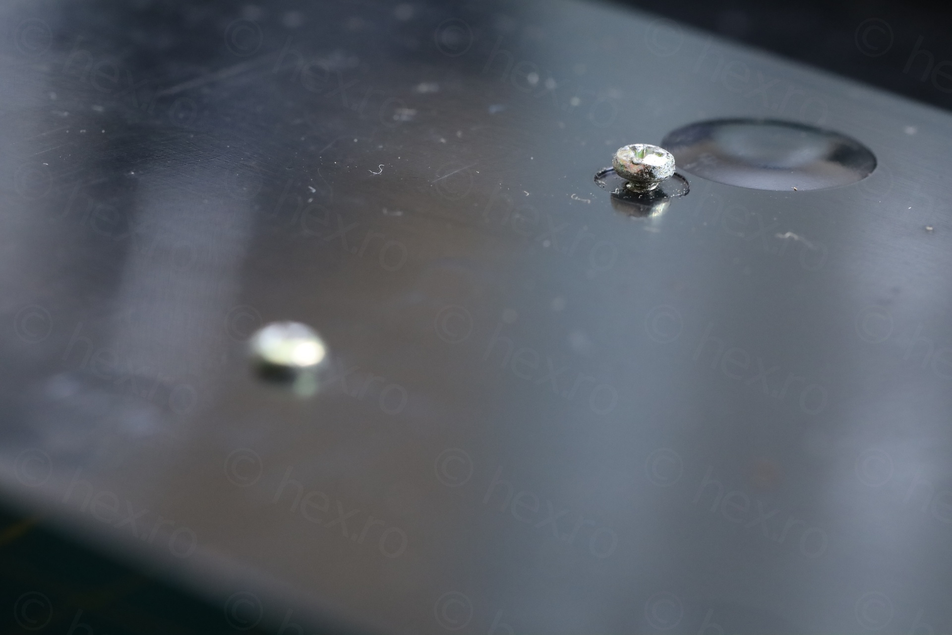
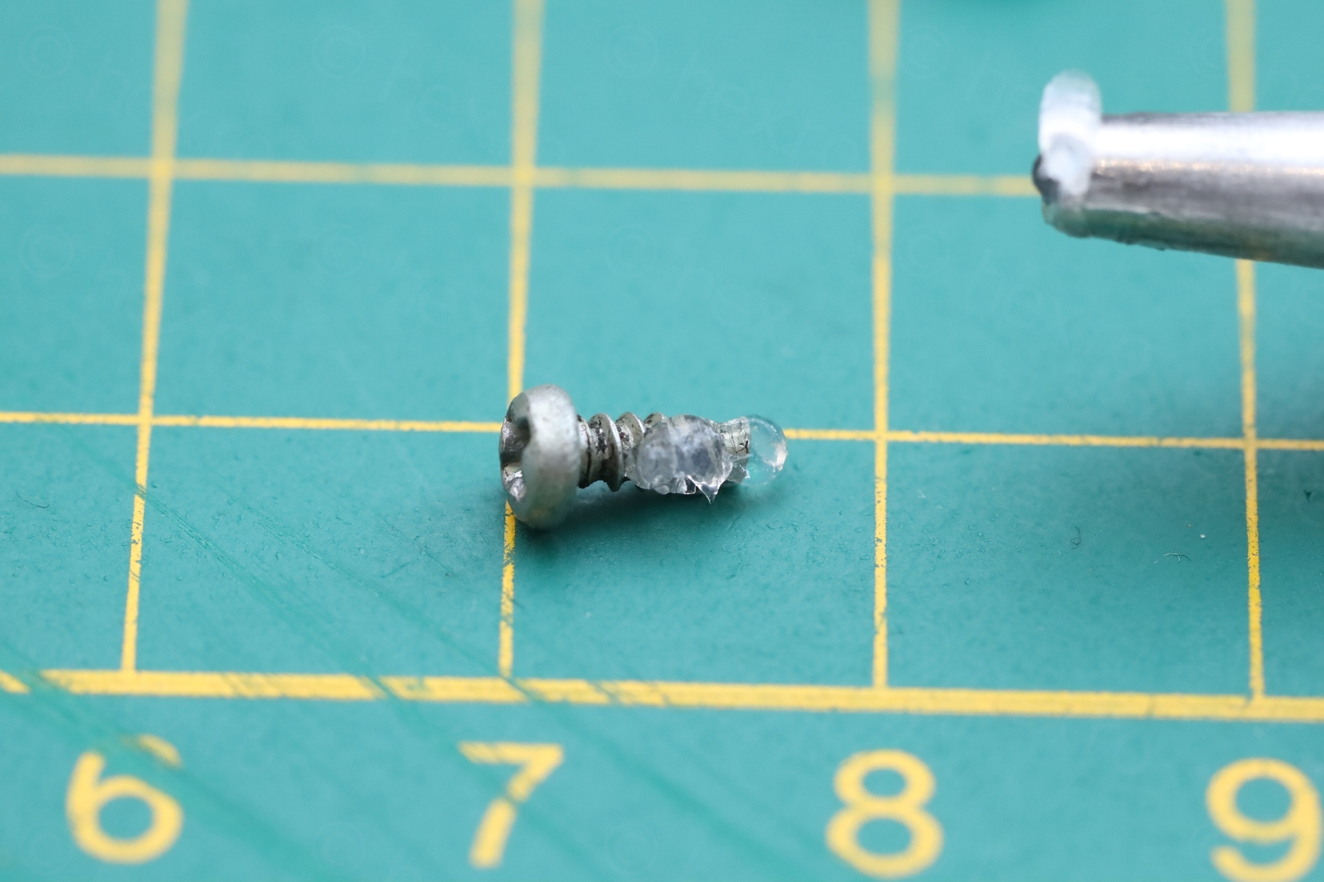
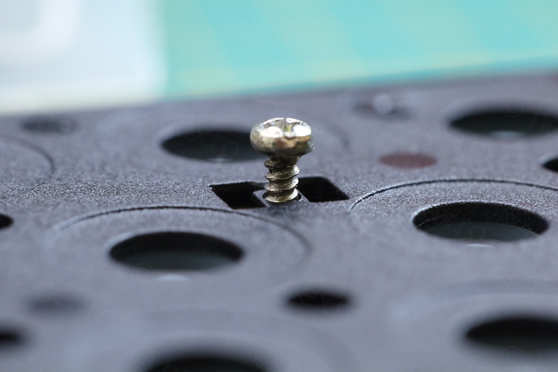
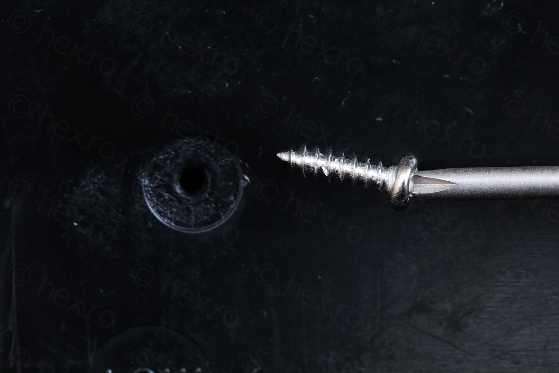
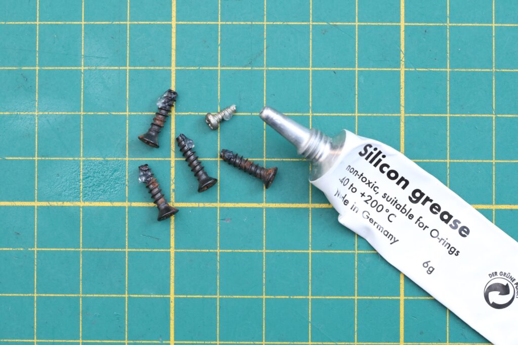
Was getting ready to finally put the keyboard back together. Installed new keyboard membrane, applied silicone grease on the screws, but, surprise. The screws were just turning in “air”, not gripping on anything, and especially, not pulling the “bow” down. The M2x6 screws were either not long enough or the screw hole were all stripped.
I found it difficult to believe that all screw-holes were stripped. The screws were also loose when I received the computer. Kept wondering what to do.
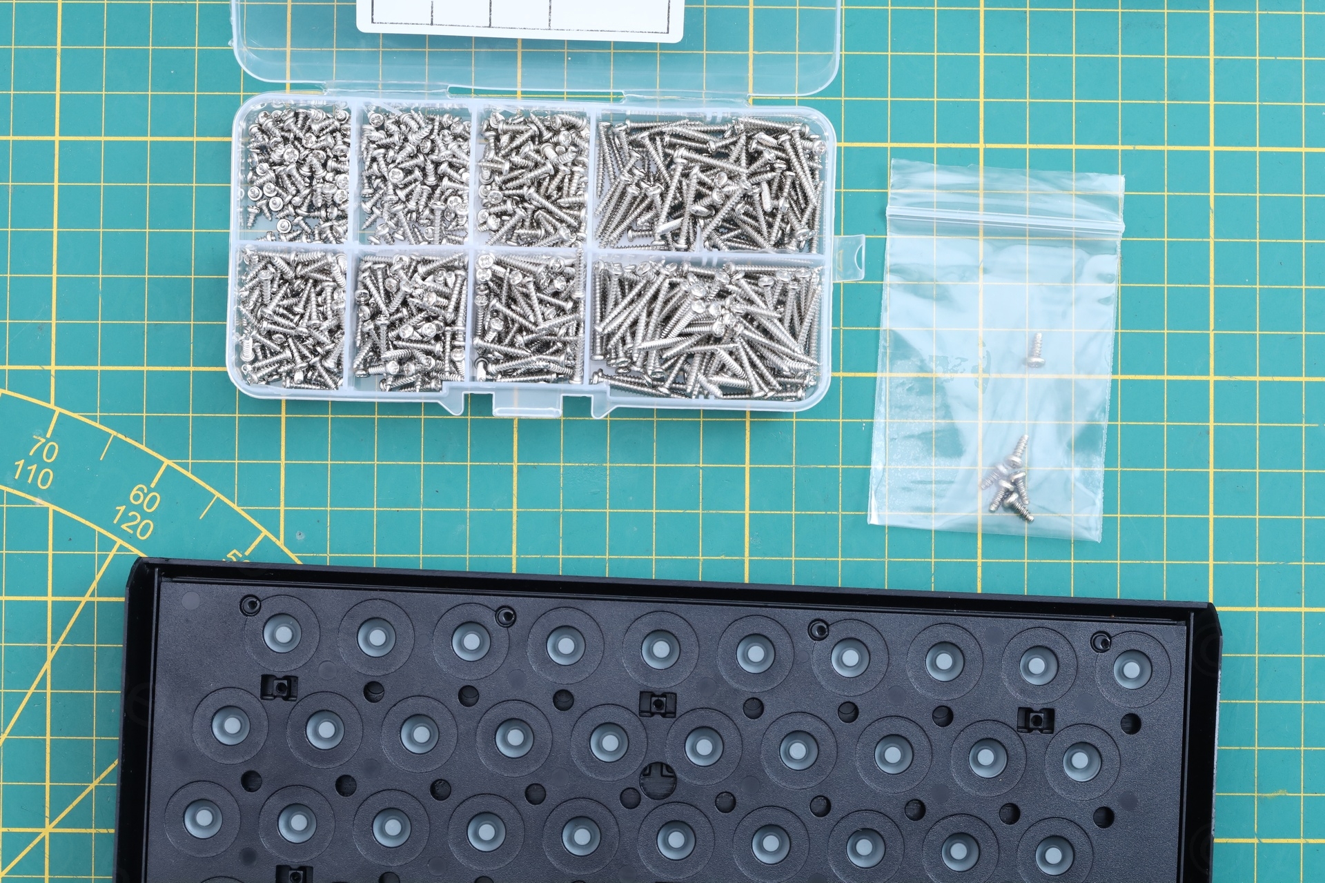
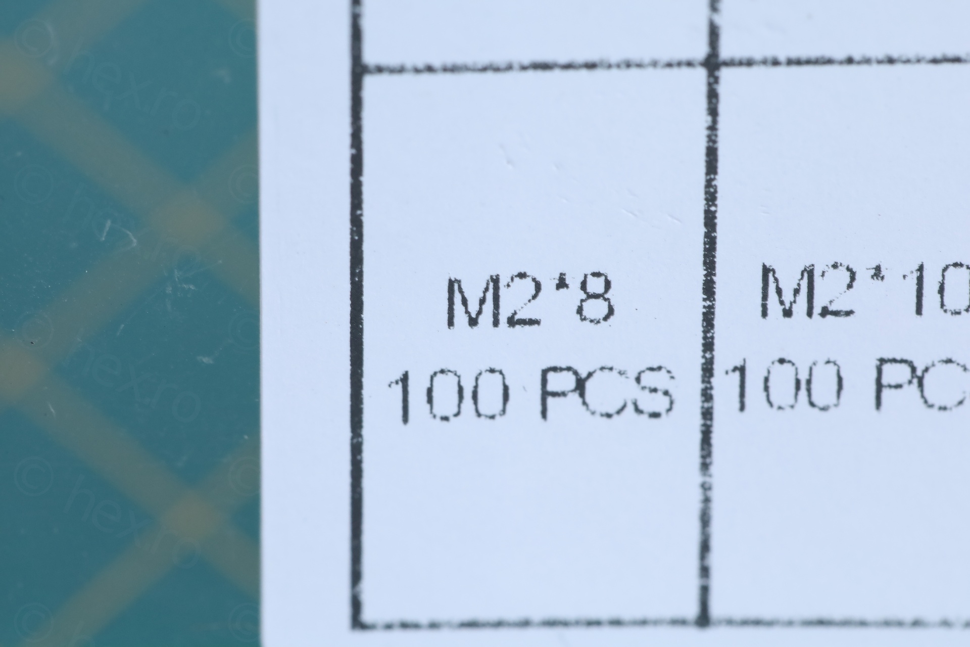
Ended up ordering a set of self tapping screws making sure they contain an M2x8 and M2x10 just in case. After more waiting, M2x8 worked perfectly. They keyboard now is well attached to the computer case and the keys don’t travel enough downwards and getting stuck.
Typing experience
The typing experience is very poor. Buttons are hard to press and unless you push exactly downwards on the center of the button, the button just tilts to the side. Thus, I agree with that info.txt mentioned in the beginning.
A small video executing a keyboard test:
Wrapping up
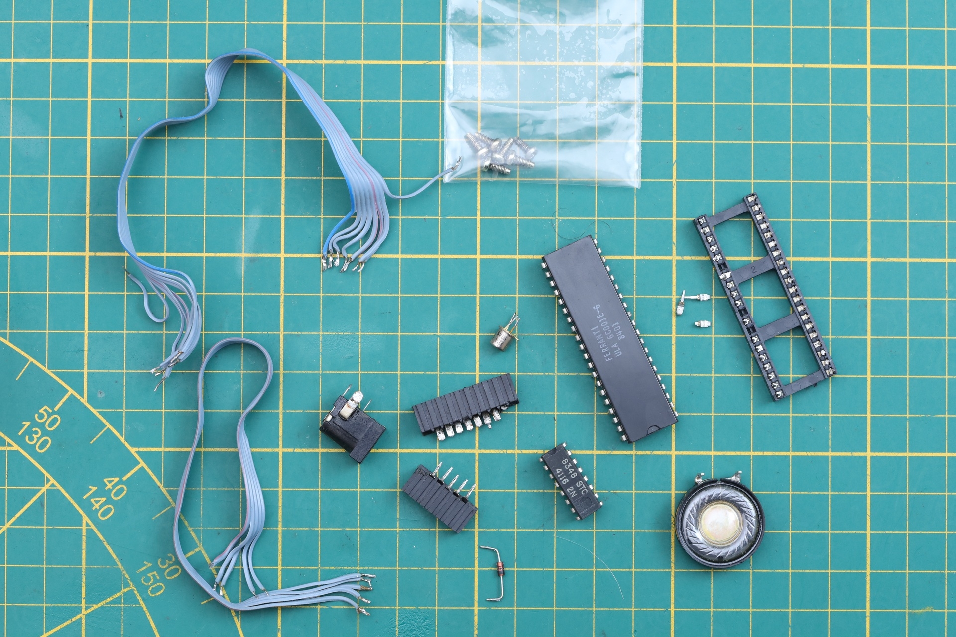
Managed to resolve all the issues. It was a very lengthy repair – order after order after order. Some of the parts removed are in the in the photo below. I ended up throwing the old speaker (along with the new one that I found open), and used a a different one in the photo, just as a reminder. I now realize I forgot to include the ON/OFF switch, as well as the DC Jack of the Power Supply. The case screws were greased with silicone grease.
Few more shots with the assembled spectrum:
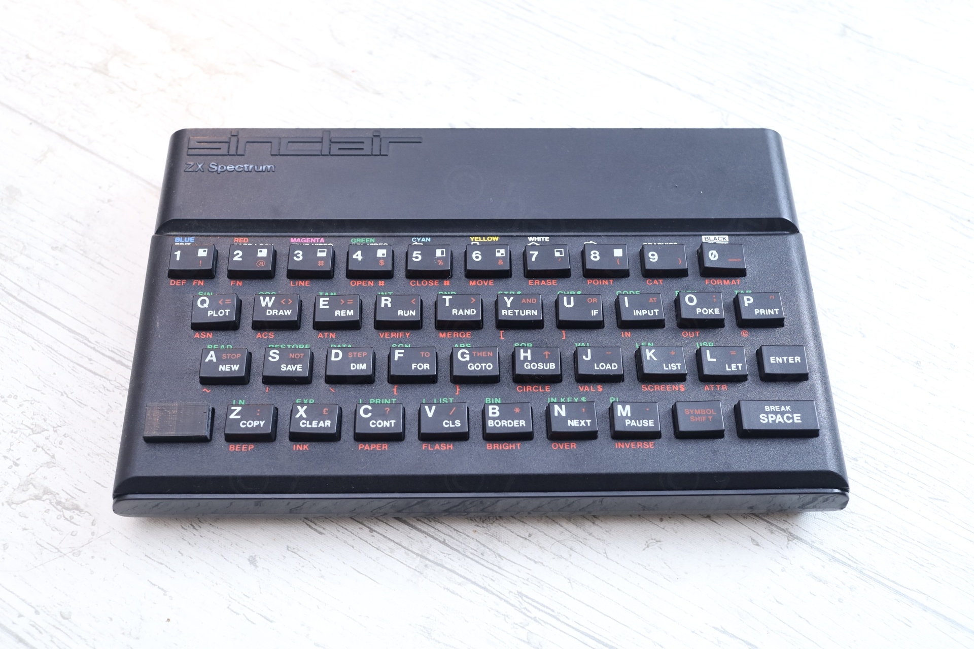
A poor computer that was used, broken, fixed, used more, broken more, then still used for profit. I wanted to preserve this piece of history that I didn’t even know I bought, until I had it.
João Diogo Ramos
Very nice work! Congrats.
To add to the information, it is a pretty common model assembled at TIMEX Portugal. The keyboard is not very good indeed and keys fall very often.
There is documentation about this and many others things in, for example, our LOAD Museum website, specifically in the https://loadzx.com/timexcomputerworld
Wish you an amazing 2025.
Regards.
João