
Table of Contents
Introduction
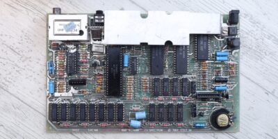
I was working on a Issue 3 Sinclair ZX Spectrum motherboard and noticed that the R55 still gets hot even after replacing D15. Replacing D15 did help reduce the temperature from >100C down to about 75C, but 75C is still too hot.
I suspected something was wrong, but there aren’t many resources to read from when trying to understand how the DC-DC converter circuit works …
https://www.tablix.org/~avian/blog/archives/2006/05/spectrum_dc_to_dc_converter/
https://www.eevblog.com/forum/beginners/zx-spectrum-dc-dc-inverter-citcuit-how-does-it-work/
… and I was a little lost on how to approach the problem.
The easiest way would have been to start taking parts out of the circuit and measure independently. The computer does run properly and passes all the diagnostic tests though, what if the problem is not a faulty component ?
If I could I simulate the DC-DC circuit and start crosschecking voltages with the real board, maybe I’d avoid butchering the board and hone in onto the bad part.
DC-DC Circuit Simulation
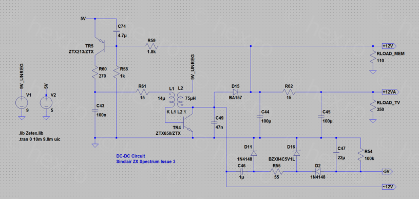
I transcribed the DC-DC circuit in LTSpice XVII:
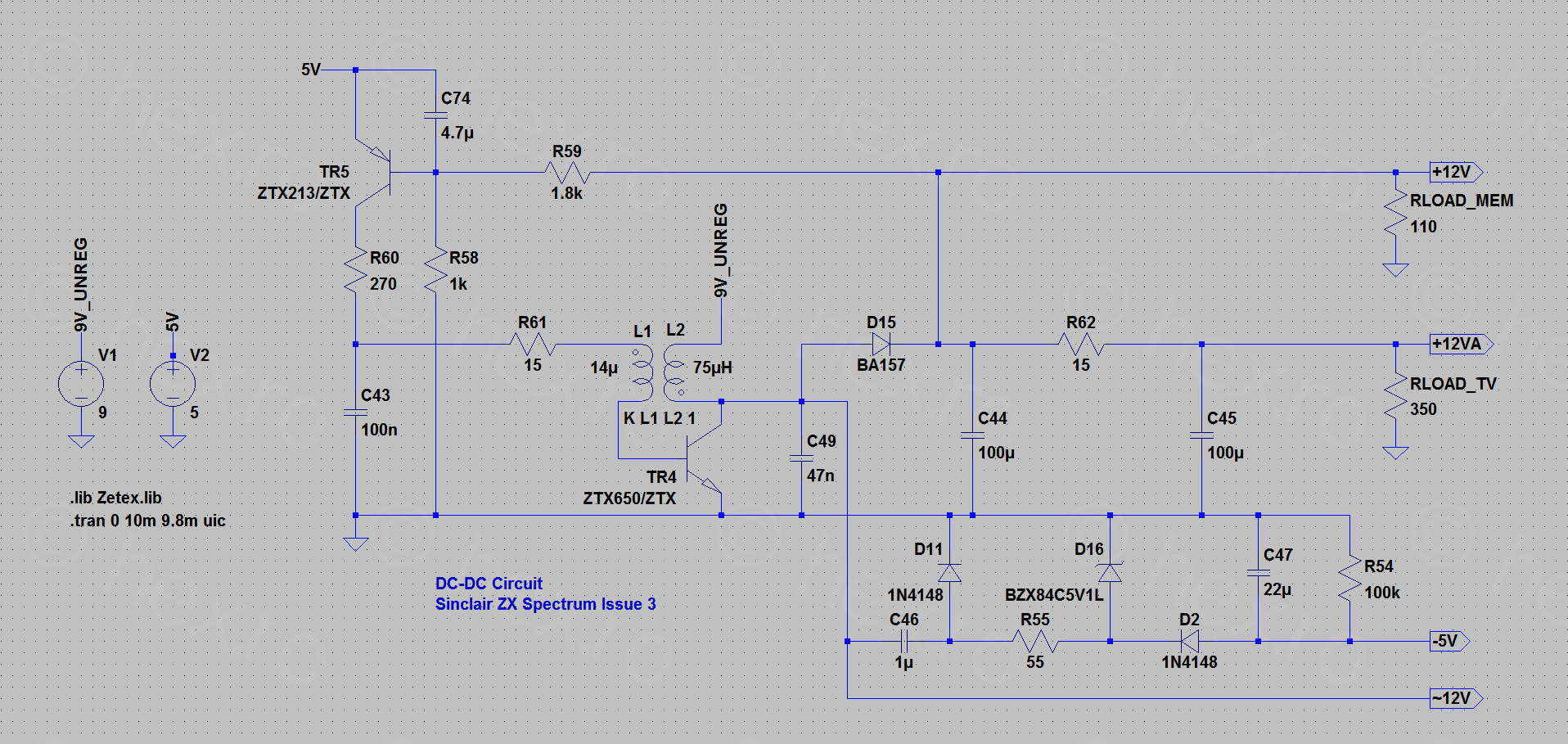
As reference, I used the Issue 3 schematics published here: https://spectrumforeveryone.com/technical/zx-spectrum-pcb-schematics-layout/
I had to overcome some hurdles though.
D16 – 5.1V Zener Diode model
My LTSpice XVII installation did not have a 5.1 Zener Diode model. I used the definitions published here https://www.eevblog.com/forum/beginners/lm317-dummy-load-circuit/msg1478818/#msg1478818 by Ian.M – by appending them to c:\Users\...\Documents\LTspiceXVII\lib\cmp\standard.dio file and restarting LTSpice. Then, I could set D16 to be BZX84C5V1L.
D17 – BA157 Diode Model
This was the most difficult to handle, since there is no model available for LTSpice XII. I had to transcribe my own using the PSpice model published by Vishay here: https://www.vishay.com/docs/87043/_p_ba157.txt
Transcribed for LTSpice looks like below. Not sure if transcribing is good, but it seems to work accordingly in the simulation:
.model BA157 D(Is=28u N=2.434 Rs=35m Eg=1.11 Xti=3.06 Cjo=21.8p M=0.6 Vj=1.97 Fc=0.5 bv=440 Ibv=0.42 tt=370n AF=1 KF=0 mfg=Vishay type=Switching)
TR4 / TR5 Transistors models
For the ZETEX transistors (ZTX213 / ZTX650) models, I used the library published here: https://github.com/juanbravo/LTSpiceIUT/blob/master/Lib/IUT/sub/Zetex.lib
This was a bit more cumbersome to setup. After copying the Zetex.lib file to the project and the importing using the “.op” button with the “.lib Zetex.lib” Spice Directive, I still had to Ctrl-Right Click on the transistors to paste the correct symbols ZTX650/ZTX and ZTX213/ZTX accordingly (with the /ZTX ending included)
Once I had the parts, I the remaining unknowns were the coil and the load on the circuit.
Coil
I feel bad to take components out if they are still working. Thus, I measured the two sides of the coil with the VICI VC480C+ milliohm meter as well as with MULTICOMP PRO MP700434 LCR Meter (Inductance mode, 100kHz).
One inductor measures 0.060Ω and 13.6µH, the other inductor measures 0.220Ω and 75.2µH. The coils on two other boards give similar results, thus, for the simulation, I went with 14µH and 75µH respectively, while setting the “Series Resistance” accordingly.
Loads
By now, the simulation ran fine producing the required voltages (+12V, -5V), but I had no clue on what would be some suitable load resistors.
For the load on the +12AC line (going to the TV circuitry), I went by the datasheet of LM1889N stating that the average current draw is 35mA. Thus, a RLOAD_TV of 12V/0.035A ~= 350Ω.
For the load on the 12V (memory), I initially guesstimated that the memory draws 100mA and started off with 120Ω for RLOAD_MEM.
This was a very good approximation, finally going with 110Ω to get the simulation to match the waveform shape present on the board:
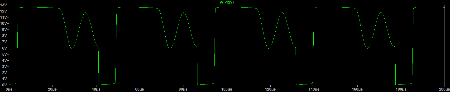
The remaining discrepancy is that the signal period is 45µs in the simulation, but 35µs on the real board. For the purpose of having a better understanding of the circuit, this is not a problem.
Findings
The Service Manual states that all resistors are rated for 1/4W (250mW) unless otherwise stated. Nothing additional stated for R55 .. thus, it is rated at 250mW.
R55 does run hot
First finding was that R55 runs hot even in the simulation!
If you Alt-Click on a component, LTSpice will plot its dissipation (power). In the plot below, I have Alt-Clicked on the R55:
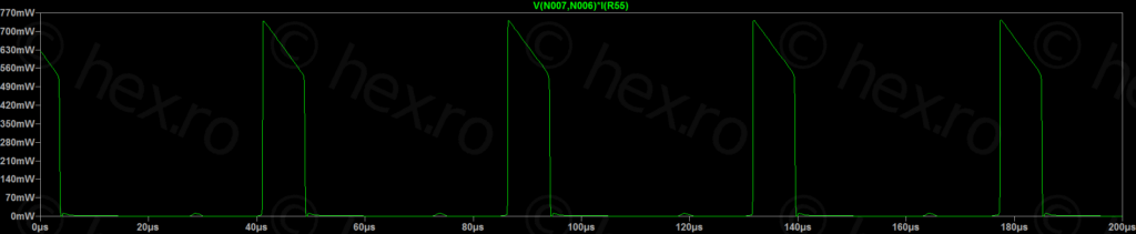
It can already be seen that during those ~8µs peaks, the dissipation exceeds the rating of the resistor (770mW peak vs 250mW rated).
If you Ctrl-Click the Waveform label, then LTSpice calculates Average Power, and surprise: 111mW of average power:
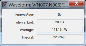
Even in the simulation, the poor R55 resistor has to dissipate almost half the power it is rated at. Thus, 75C in reality doesn’t seem wrong. The real motherboard is working fine.
DC-DC circuit runs better at 10V
The case of Sinclair ZX Spectrum computer shows “9V DC” above the power input jack. The schematics mention 9V. Many online shops are selling 9V power supplies specifically made for Spectrums (with center pin negative). 9V everywhere. All this time, I was powering the board with my desk bench power supply set at 9V.
While de-cluttering the schematics and moving the power supplies to the left, I wanted to test that everything still works. I upped the simulation voltage to 10V (instead of 9V) just to make sure results are different. They were different, but …. “much better” different!
The frequency of oscillations of the DC-DC circuit reduced quite a lot:
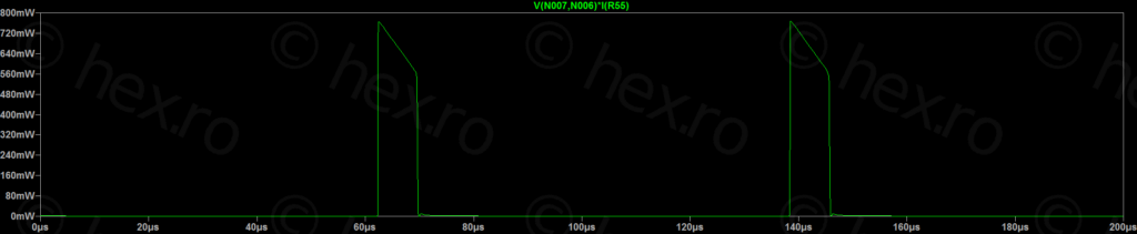
This was very very interesting. Extending the plot interval to 1ms to have a better average:
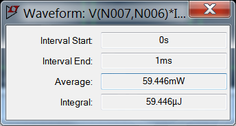
This is a big improvement, for R55 to drop to an average 60mW (when the board was powered with 10V) from an average of 110mW (when the board was powered with 9V).
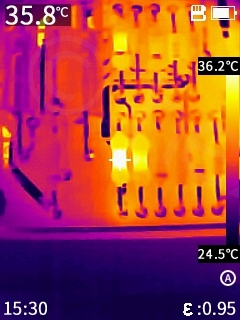
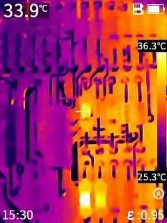
Testing it live by rising the power supply to 10V – I took a temp reading and soon after, I lowered the input voltage to 9V and checked what happened with the R55 temperature:
Almost 20C more just from 1V lower on the power supply!
Below a small table with the Input Voltages vs Power Dissipated by R55 (over 1ms interval) that I ran through the simulation:
| Power Supply Voltage | R55 Dissipated Power |
| 7V | 237.51mW |
| 8V | 156.17mW |
| 9V | 102.51mW |
| 10V | 59.446mW |
| 11V | 48.491mW |
Original Power Supply
Another problem, also visible in the simulation, is that at more than 12V input voltage, the DC-DC circuitry stops oscillating. It ill not produce the -5V needed by the memories. Thus, I would not get close to 12V.
Initially, I wrote the text above, based on the simulation results. However, I had the chance to test an original Sinclair ZX Spectrum power supply – EURO 1400 – with an Issue 3 board.
The original power supply runs at 12.35V once plugged onto the computer (measured on the Input pin of LM7805). The line voltages are the following:
- -5V -> 4.73V
- 12V -> 12.34V
- 5V -> 5.01V
The Sinclair ZX Spectrum coil is also buzzing (I can hear it now).
Thus, it is not true that the DC-DC circuit shuts down, it still oscillates (at least at 12.34V) but much slower – however, most likely the draw on the -5V line is so little, the -5V capacitor can still hold enough power not to starve the memory circuits.
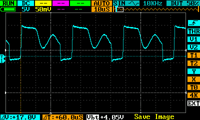
Oscilloscope shots from the left terminal of C46 (Issue 3 board) – but this time, 100uS time division. The frequency is allover the place, I had to pause the run and came up with the 3 samples below:
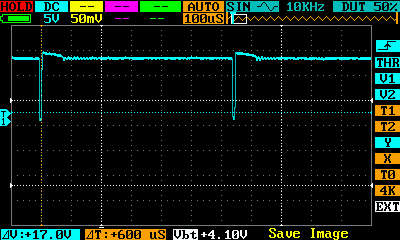
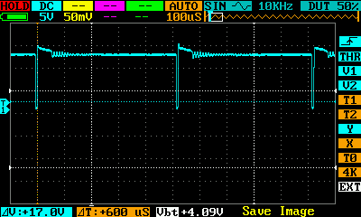
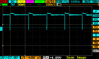
The DC-DC circuit still oscillates, but slower, it is closer to shutting down. In the simulation, at 12.7V it still oscillates at 733Hz, but at 12.8Hz it already has a weird waveform.
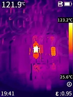
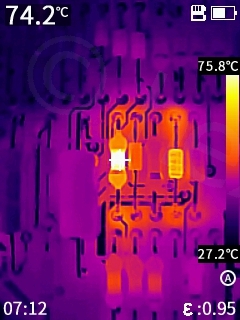
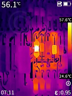
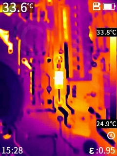
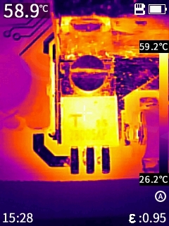
The Infrared temperatures at 12.34V on the In of LM7805 using the original power supply:
Conclusions
There are few forum posts (here, here, …) where people ask what would be the ideal power supply voltage for a Sinclair ZX Spectrum. The board issue is not specified. Some replies state that 7V is still acceptable, based only on the fact that 7805 would still be able to generate a stable 5V. One more stated advantage is that the 7805 would run cooler. These replies are partially correct. They are true for 7805, but the replies neglect the fact that the DC-DC circuit has to work ‘harder’ to generate the 12V if you lower the input voltage. This additional “work” (frequency increase) – at least on Issue 3 board – puts a lot more stress on the -5V line Zener diode which in turn makes R55 run much hotter.
Based on the simulation, the ideal power supply seems to be around 10V. The LM7805 won’t get much hotter (it has a heat-sink anyway), but the R55 will run much cooler.
This simulation is based on an Issue 3 board. Since the power supply circuity changes between various issues, I can’t generalize to others.
If your R55 gets too hot, maybe check the Input voltage on LM7805 input pin. I wasn’t doing that, trusting the little SMPS output reading of 9V. What I didn’t know was that the two crocodile leads were each approx 0.9Ω (now measured with VICI VC480C+). At 0.55A power draw, the voltage drop on the leads was 2*0.9*0.55A ~= 1V -> thus, the board was only receiving 8V.
Krzysztof Arciszewski
Viulian, would you be able to share the ltspice model descibed? That would help me much fixing faults with my spectrum. Thx.
viulian
Hello, thank you for writing!
I have on my TODO list 🙁 but not sure when I’ll get to it. I would like to host it on bitbucket, but I need to write the README file etc. I’ll respond with a comment, but it will take some time. What is the problem with your Spectrum ?
Best regards,
Krzysztof Arciszewski
TR4 keeps overheating and fails.
I have recreated the DC DC coverter on breadboard with the coil soldered out from my spectrum and again TR4 overheats. All the components are new but the coil. Loks like there is no proper oscillation on the coil. So I try to understand how it should work.
Krzysztof Arciszewski
I have rewound the coil but it does not change anything. Looks like large current simply flows thru the coil so it overheats TR4.
1024MAK
Given that the current requirement for the -5V rail in an unexpanded ZX Spectrum is quite low, the value of R55 could have been a bit higher (hence reducing the power dissipation). In earlier versions, the equivalent resistor was 2.2kΩ.
R55 running at 187mW (250mW with a suitable derating to take account of the inside of the computer being hotter than 25°C) or lower is well within it’s rating.
Later revisions add capacitor C78/C80, this prevents DC from flowing from the +9V (nominal) rail through the coil and into the +12V rail. Hence reducing the problem if the +9V (nominal) rail is higher than 12V.
See my blog post here: https://8and16bit.blogspot.com/2019/08/zx-spectrum-16k-48k-and-plus-models-dc.html
Most U.K. Sinclair UK1400 PSUs (rated input voltage 240V AC) typically have an on load output voltage of between 10.5V to 11.9V (with just a ZX Spectrum connected).
Keep in mind that if the mains voltage is higher than the rated input voltage, the output voltage will also be higher. There are also slight differences between PSUs as they were made by a number of companies for Sinclair.