


Introduction
The AI Sol Nano LED light fixture installed over my mini reef has one very nice feature – “fade in” to a set brightness in the morning and “fade out” to Moon light in the evening. I wondered if I can build something similar for the 3 other LED lamps I own, a Dennerle PowerLed 5.0 and two Dennerle Style Led L.
Dilemmas
The standard way of controlling the brightness of an incandescent light bulb is using Pulse Width Modulation (resistive load, voltage source). LEDs are best driven by constant current source and if Dennerle built it like this, then there could be drawbacks in using PWM to alter the brightness (see Is It OK to PWM a current source?).
Since I didn’t want to dismantle the power plugs, the only remaining thing was to try things out – maybe Dennerle build something that has no problems being driven with PWM ?
Hardware choices
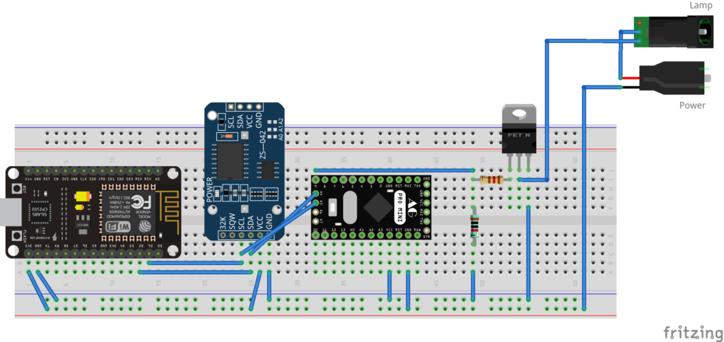
I had few Nodemcu V2 CP2102 available (ESP8266), some RTC modules and a bunch of IRLZ44N MOSFETs.
I decided from the beginning to go with an RTC module, mainly as redundancy. A bad scenario could be power loss. ESP8266 boots much faster than the WIFI router, and then it would need to keep trying to fetch the time. Or what if there is a bug in the router, I’m not home to reset it, and then the lights are out until I can intervene ? Thus, the control module should be as independent as possible and very rarely to need WIFI.
The RTC modules are the infamous ZS-042 DS3231 which need a trace being cut otherwise they keep on trying to charge a normal (non rechargeable) CR2032 battery. However, reading more topics online, I found out that you can disable the charging circuit just by de-soldering a specific SMD resistor. I went with the de-solder, less destructive than cutting a tiny trace.
I chose IRLZ44N because of VGS(th) of 2V, low Rds(on) = 0.022Ω and large ID = 47A. It can be easily opened by 3.3V (at least according to the schematic I found online) thus there should be no problem controlling it. The lamps consume much less than its maximum specs. The power brick of Dennerle Power Led 5.0 the is rated for 21V @ 0.22A and rated 13V @ 0.55A for Dennerle Style Led L.
Once the prototype was taking place, I discovered that the ESP8266 is not so good at handling PWM. At low duty cycle the lamps would flicker. Even with the latest library, but they would still flicker while I was changing the duty cycle from 2% to 1% for example. This wasn’t such a big issue, as they were not supposed to stay lit at 1% for long, but still frustrating.
On top of it, another problem: at the lowest duty cycle the LEDs were still bright! I could not get them to be just dimly lit. Turns out it is because ESP8266 has a lower resolution PWM, and according to a topic here by Ingo, no such problem exists on Arduino, as Arduino has 16 bit PWM is available. Hmmm …
As it happens, I also had some Robotdyn (Arduino) Pro Mini 3.3V lying around! This confirmed what Ingo said, at 1% the lamps are very dim and … surprise surprise, no more flickering! Decided to bite the bullet and include an Adruino Pro Mini into the build.
In summary: the ESP8266 will host a small webserver (and keep track of Wifi connections / NTP updates) and will also calculate the PWM duty cycle depending of the time of day and the ramp-up/ramp-down settings. ESP8266 communicates using I2C with both the RTC module as well as with Arduino – the Arduino communication is ‘send’ only -> the PWM duty cycle. It is then up to the Arduino to execute the I2C command. The MOSFET pin is connected to Pin 9 of the Arduino (the TIMER1 / configured for 16bit PWM) output pin.
Software
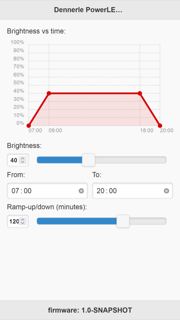
As you can see, the interface UI very simple. A chart to show a representation of the light intensity pattern, the Maximum Brightness, the on / off time, as well as the Ramp-up/down value. I have not implemented the ‘moonlight’ feature, although this would not be so hard now.
The algorithm is simple:
* if time is available from RTC module, calculate the PWM duty cycle and send it to Arduino
* try to connect to WIFI and then periodically to NTP server, if all is ok, refresh the RTC time, if not, try all again later.
* start a Web Server where a small jQuery (if jQuery can be considered small) + jQuery mobile interface is served from the SPIFFS file system
* on submit -> update the values in the configuration file
As libraries, I have used jQuery 1.10.2, jQuery Mobile 1.4.5, jquery ajaxmanager and Chartist.js 0.11.4.
Network setup
I decided to put the NodeMCU modules in their own VLAN. Using OpenWRT is pretty straightforward – the boards do not have internet access, although I can still connect to them to reach the UI.
3D printed project box
As an aquarium owner for many years now, I know that the place around the aquariums is prone to mini accidents. Maybe some drops of water, maybe some food package can be dropped, etc. Figured out from the beginning that I would also 3D print the cases for the projects.
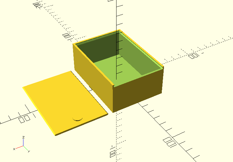
It was a bit difficult to find the right box, so many choices, but I settled on a “Parametric slide lid box (by koehn)” that was made in OpenScad. Very easy to configure exactly to what was needed.
I have also 3d printed 4 small supports for the motherboard, so that the movement inside is reduced, and also, that the bottom wired part is not rubbing against the case. You will see them in the gallery below mounted on the left most circuit board.
Problems / Limitations – 1 year mark
ESP8266 is extremely slow in handling Ajax events. It is so slow I had to use jQuery ajaxmanager to prevent concurrent Ajax calls. Thus, the sliders are rather slow, much faster just to type the value in the input field. I did consider at one moment to use Raspberry PI Zero for this project, but I didn’t have 3 available, and rationally, NodeMCU was much cheaper and does the this job.
In 1 year there was only one single problem. One of the modules become very slow to the point where not even the UI was loading anymore. Hard to understand why – especially since nothing is provided by default for debugging or “post mortem” analysis in this micro-controllers world. The easiest was just to power cycle it (would it have been better to use a RPI Zero – easier to monitor, keep track of resources, etc ?).
Except this lockup, everything works well. The power transformers of the lamps do not get warmer. I still have this nagging feeling that what if the power bricks are not meant to be controlled via PWM and maybe I’m pushing it ? I’m sharing my findings here, but if you decide to build it yourself, you assume the risks …
Photos / Videos
Gallery:
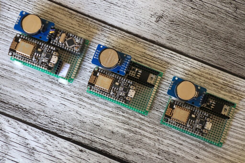
Work in progress … 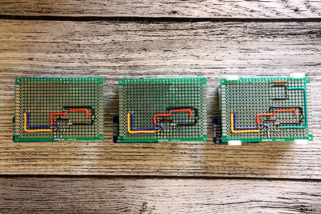
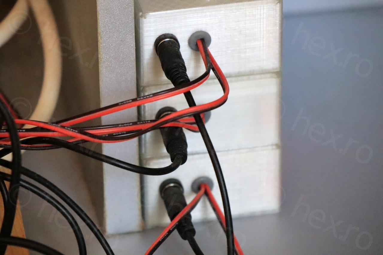
Back side. 
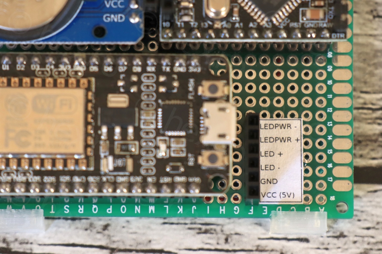
Tiny matching legend. 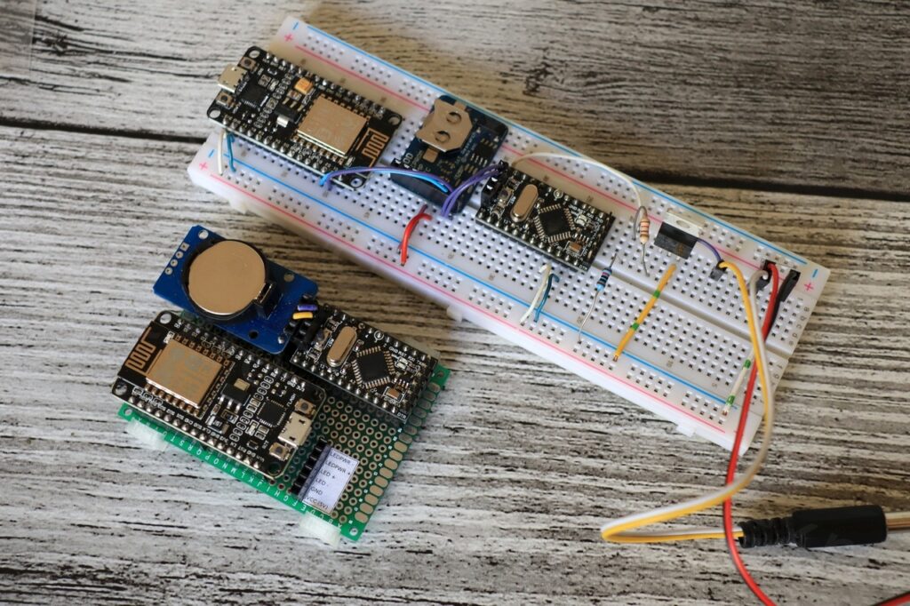
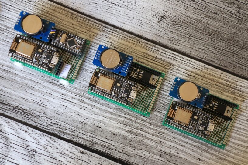
Prototype vs Finished. 
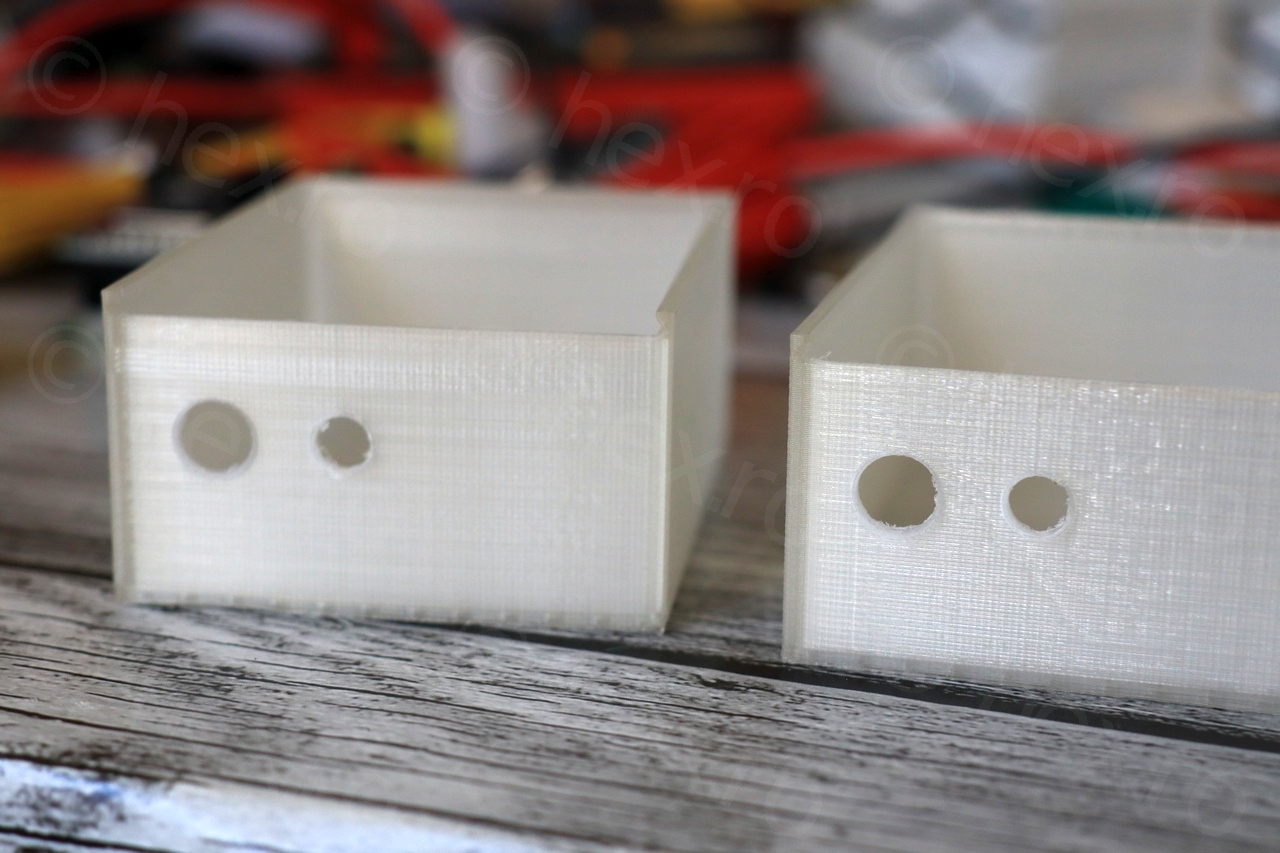
3D printed boxes. 
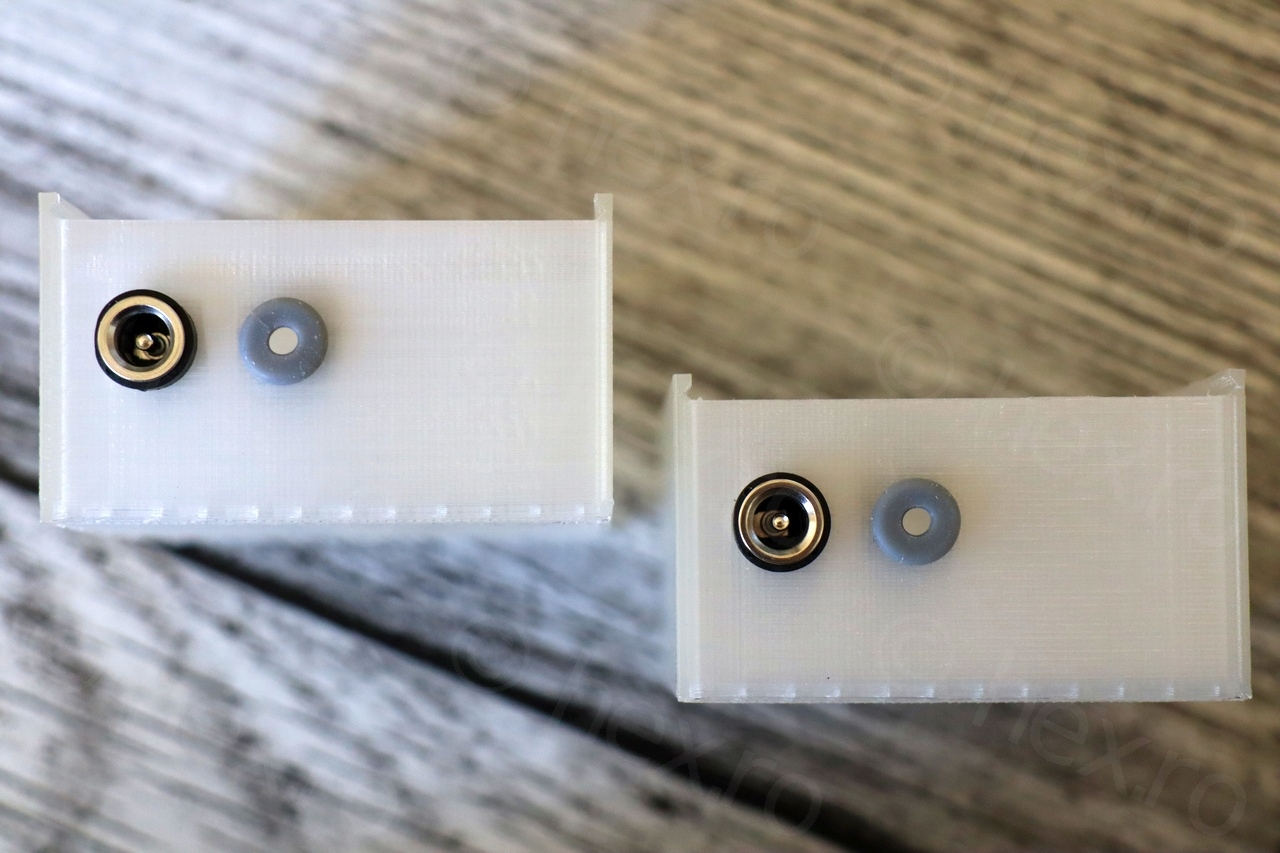
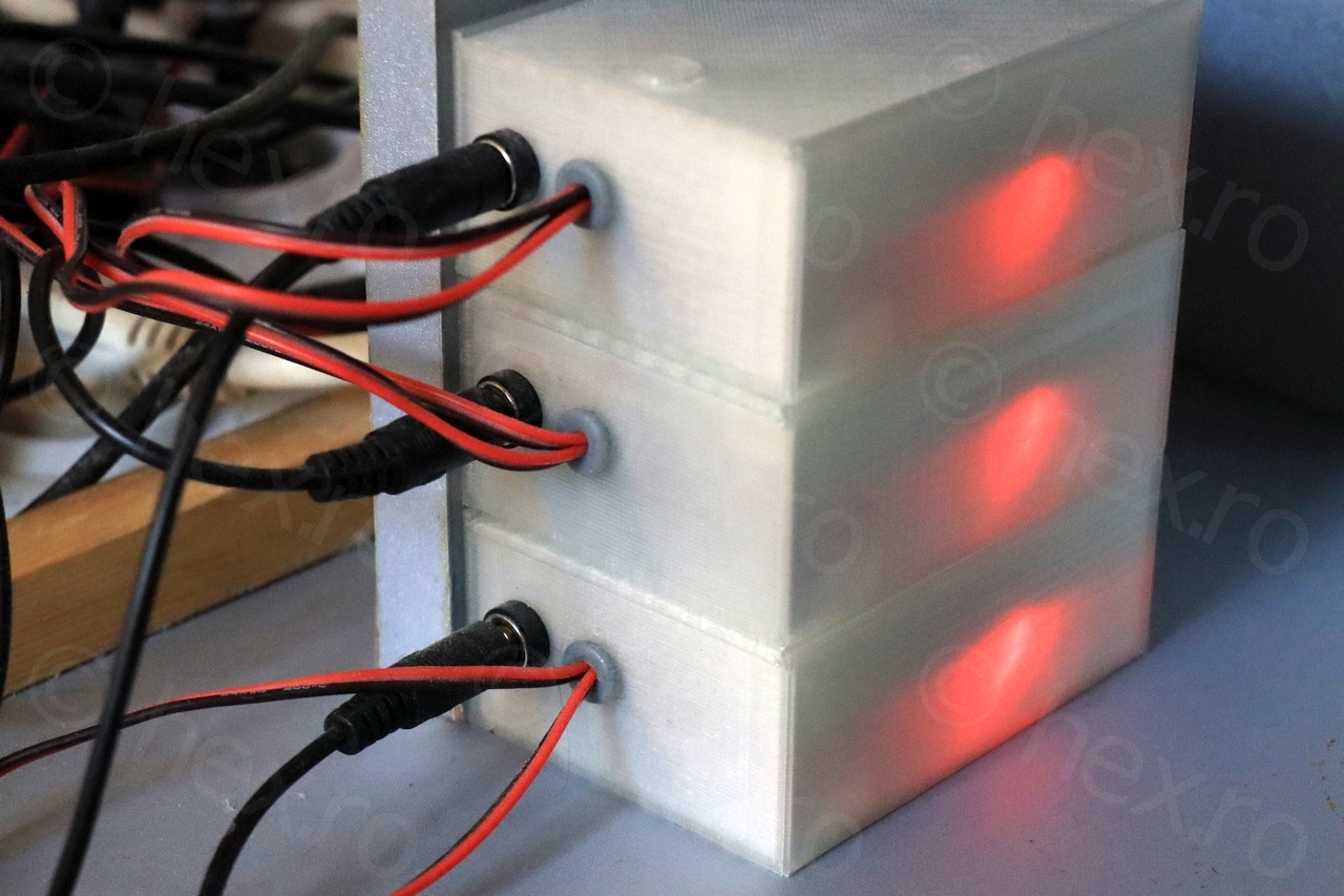
Power plug + cables port with rubber gasket. 
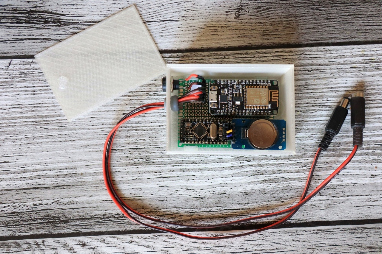
Packed inside and wired. 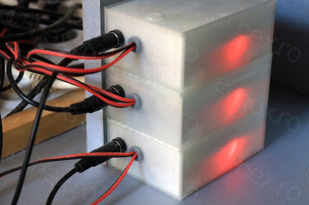
After 1 year. 
After 1 year.


kerboull
hello,
i am interresting with your project ‘DIY WiFi Dimmer for my Dennerle LED lamps’.
its possible to send to me the programme .
Best regards