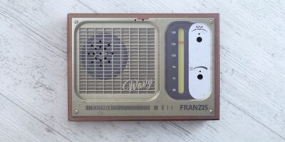
Found this tuner at a local second hand shop and decided to purchase it based on two factors – was able to find its service manual online and according to the manual, there was an old school tuning capacitor inside.
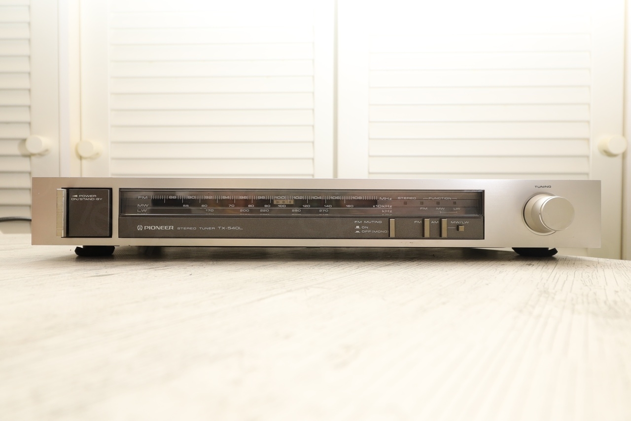
Once I got home, I discovered the radio was not tuning properly. It has an interesting design – the tuning pointer comes with 3 LEDs, two red arrows and one green and round in the middle. The red LEDs indicate where to move the tuning knob to tune into the station (either to the left or to the right).
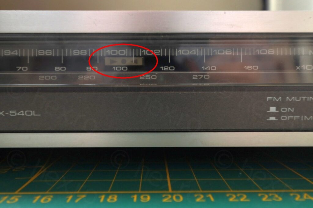
This particular tuner was showing that you have to tune a bit to the right, to get to the station, but:
a) just before tuning into the station, the audio became very noisy
b) once tuned into the station, the audio was very weak.
c) only the left LED was turning on (not the green, nor the right LED).
I’ve recorded the behavior:
Opening up
This looked like a very good opportunity to improve my ‘repairing radios’ skills. Radio was the first thing that opened my curiosity to electronics – life took a different path though – and now trying to catch up with that very old itch 🙂
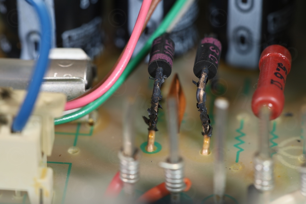
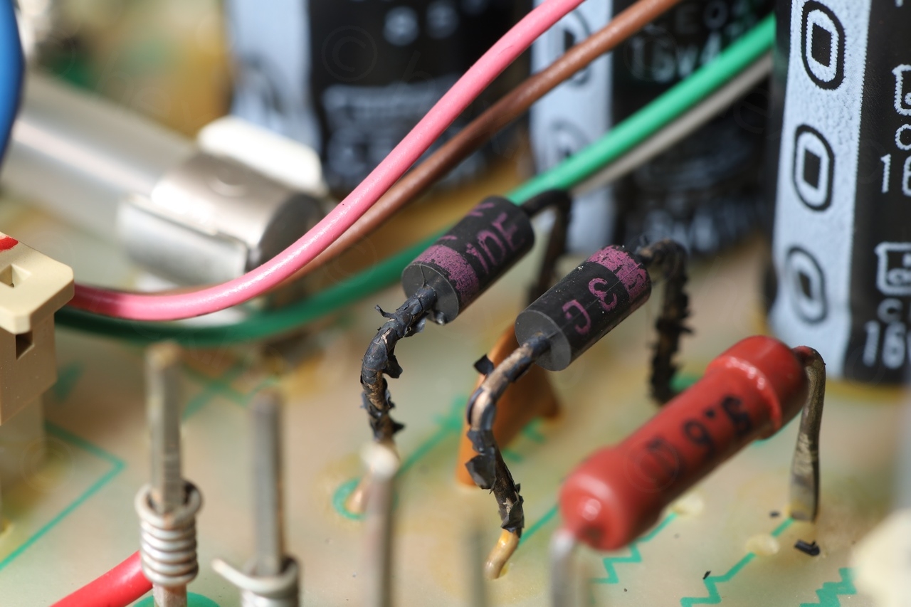
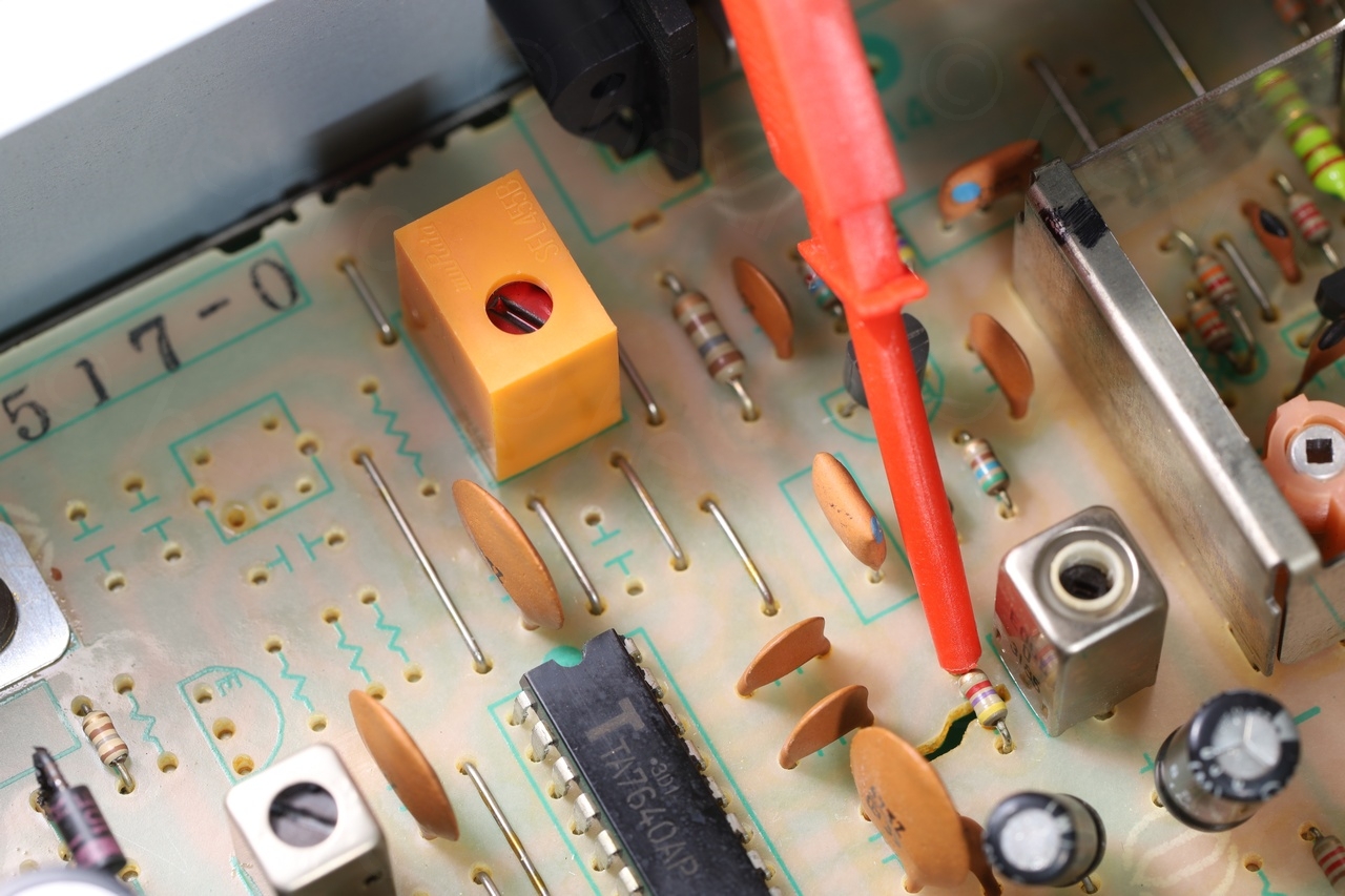
At first view, the radio looked very clean inside, and except some diodes that looked like they were overheating, nothing else special:
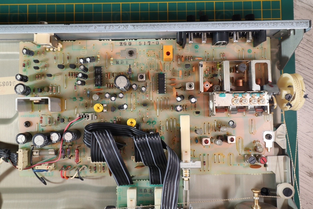
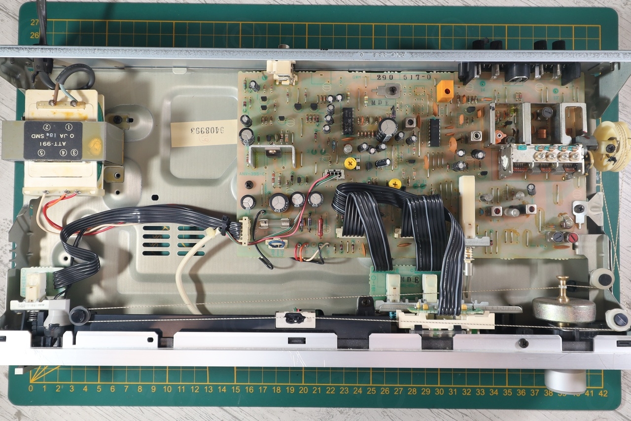

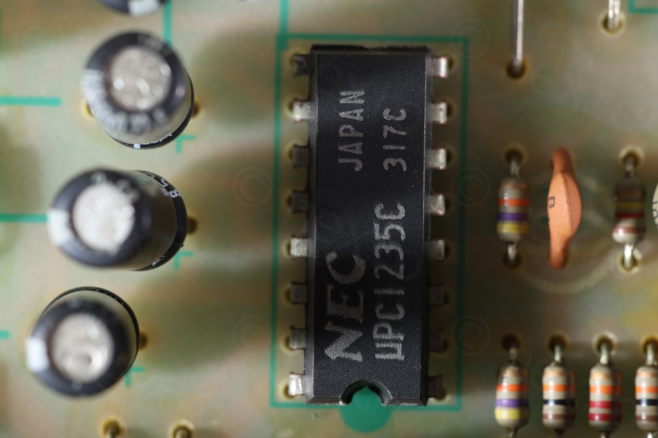
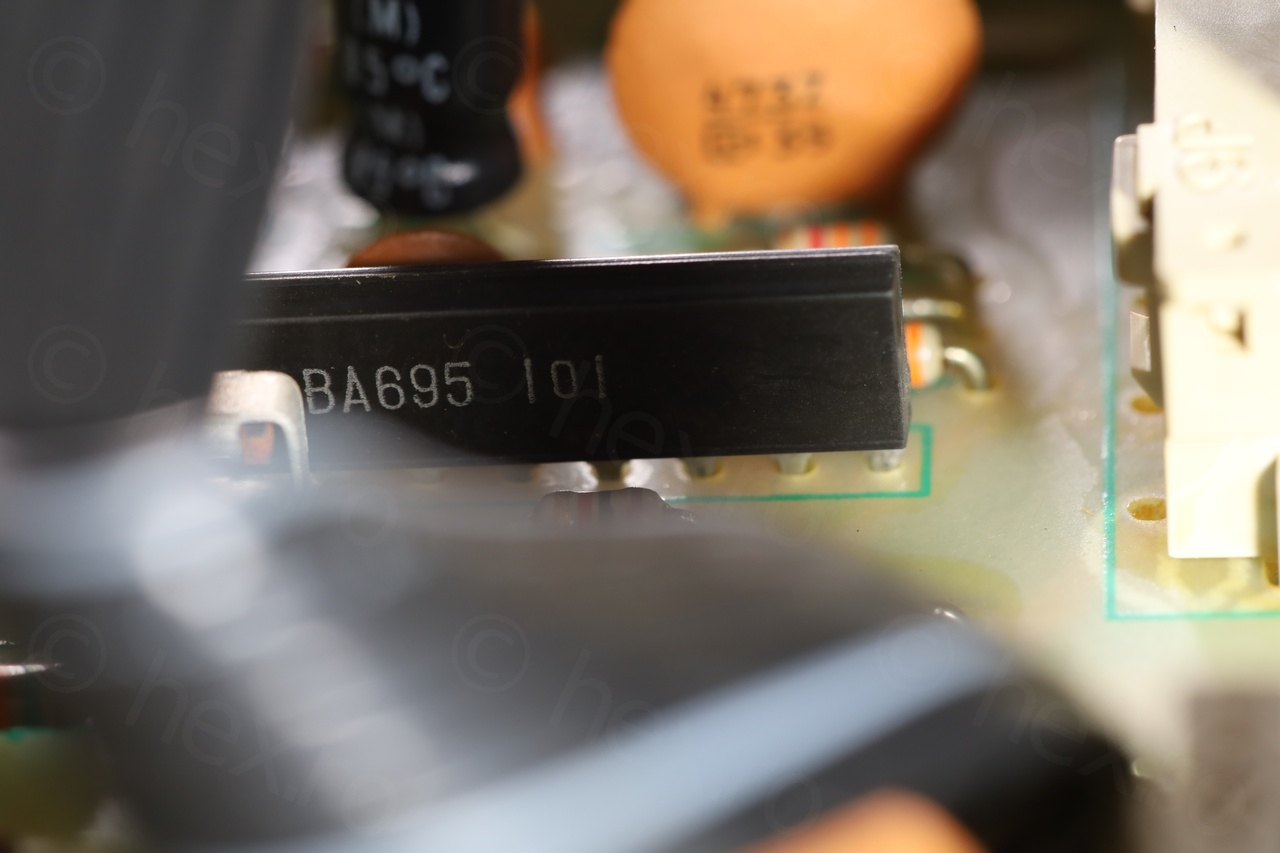
Below few more pics with the ICs, the burnt diodes and the two 10.7MHz ceramic filters:


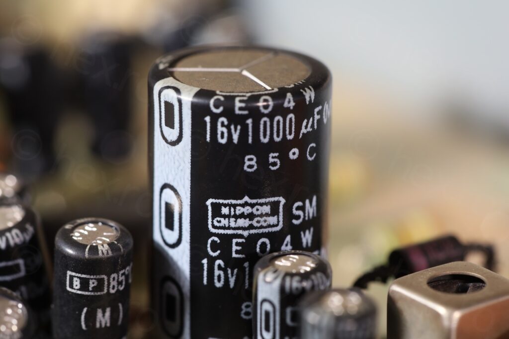
Since many repair videos on the internet suggest to just replace electrolytic capacitors before any other diagnosis, the surprise was finding Nippon Chemi-cons inside. This is a reputable brand, measured the larger ones in circuit using ESR meter and they were fine, thus, this looked like a dead end. A great time saver, but it dawned on me I will have to do real diagnosis.
Diagnosis
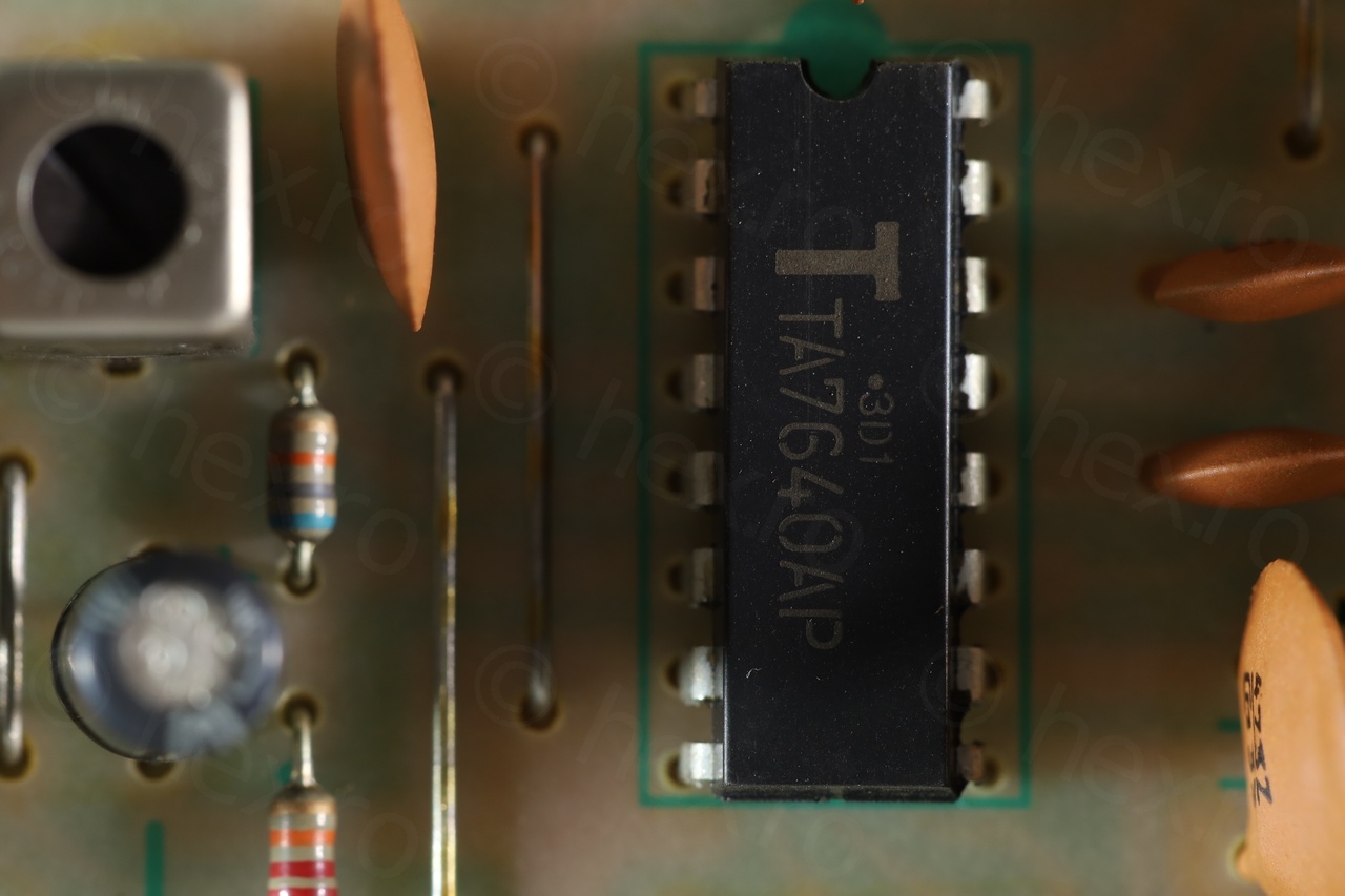
I’ve started by measuring the voltages on the FM Detector IC ( TA7640AP ). They were good. At this point, I could not decide what would be the way to continue the diagnostic. I would have wanted to have an FM emitter to be able to emit a sine wave, but without … I could only try to see how the signal looks at the output of the ‘FM front end’ (which arrives to PIN 15 on the TA7640AP).
I have connected oscilloscope’s Channel 1 to PIN15 (FM IF IN) and Channel 2 to PIN9 (DET OUT). In the video below, Channel 1 looks green and Channel 2 looks purple.
I couldn’t make sense of what exactly was arriving on PIN15, but as I was tuning into the station the signal just increased in amplitude. It was obvious the signal is properly arriving to the IC. The signal on PIN9 looked like audio signal – and just as by ear, the oscilloscope confirmed: when signal on PIN15 was maximum (tuned into the station), the audio level dropped significantly – but was much stronger and noisier just navigating left or right of the station:
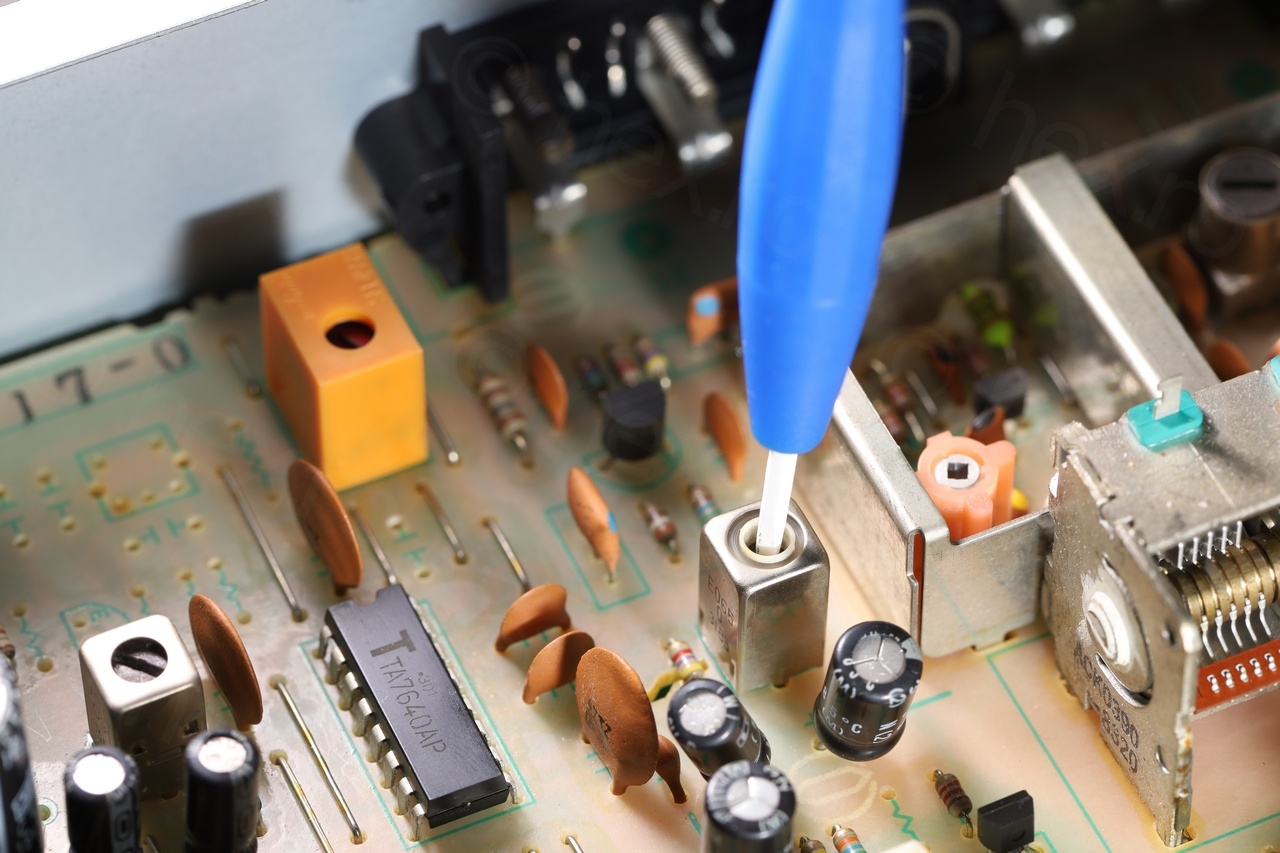
I was trying not to de-solder any component – to continue the diagnostic as is. Without really understanding nor knowing how to test the inner workings of the IC, I tried to see what other signals are present. An interesting PIN to look up was PIN11 as it was going to an external FM Detector Coil.
To my surprise and luck, probing the pin with a 10x probe made the audio work perfectly! Not only that, but holding the probe onto the pin, the LEDs of the tuning pointer started functioning properly, the center one was lit Green, confirming that station is properly dialed into!
Why would an oscilloscope probe make a difference ? Probing with the probe set to 1x made the audio totally disappear, but switching to 10x just magically fixed everything. Hmmm. In a moment of insight, I realized that it may be the probe’s parasitic capacitance was interfering with the small capacitor inside the FM Detector coil (T101):
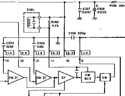
In the datasheet of the IC, the FM detector was described as having a 47pF capacitance, thus, a very small value. If the hypothesis that a small additional capacitance ‘re-tunes’ the coil, then not only a oscilloscope probe should work – but also just piece of wire!

And it worked too! Now the radio was tuning perfectly and audio was working. The video above also shows the behavior with the wire added to the R110 resistance.
Fix
I was reluctant to start messing with the FM detector coil, but on the other hand I had no other instruments that would help me test its behavior. I took note of its position and started turning it slowly. Audio became stronger and stronger until it peaked. Turning it a little around the peak would lit up either the left LED or the right LED.
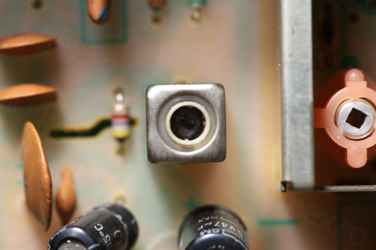

While taking a macro shot of the detector, I saw that one part of it was chipped (you can notice in the last photo above). Not sure if this is a manufacturing defect, or if somebody else was inside the radio trying to fix it ?
FM Scale alignment
Even before fixing the reception, I noticed something is also weird with the dial pointer – it was indicated let’s say 102MHz but the radio station was in fact emitting at 102.8MHz. This was consistent across the FM band, the lower side was off by around 0.6-0.7MHz, the higher frequencies were off by 0.7-0.8MHz.
The LW / MW bands were unaffected, I tested them with a Siglent Arbitrary Waveform Generator. Also, when the tuning pointer was at the extremes, the tuning capacitor was indeed either fully meshed or fully open. So there was nothing wrong mechanically …
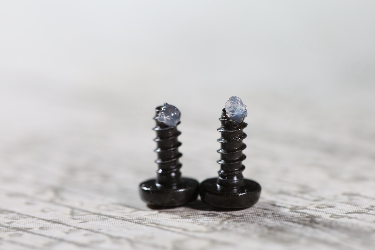
I observed that in the FM “front end” stage, there were two tunable parts, a coil + a small capacitor in the area designated as “Local Oscillator”. Below, it is indicated as TC3 (lower left):
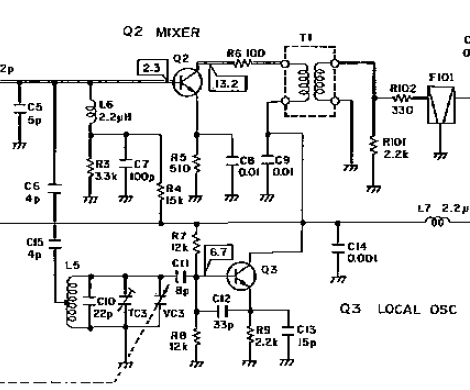
TC3 is the gray capacitor with an arrow. It was very touchy, but using a ceramic screwdriver I was able to turn it a bit to the left (moving a tiny bit, retune the radio, etc), until I got the dial pointer to indicate correctly on the scale:
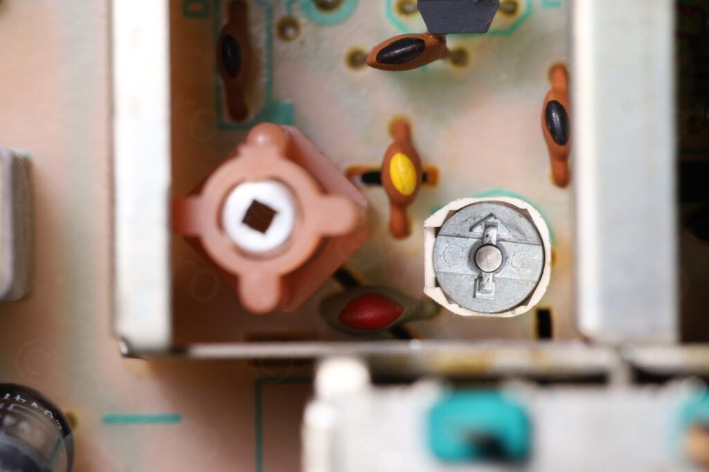
Reassembling the top was easy, a little silicone grease added on the screws and that was it:

Here are the results:
Happy I found this radio and that I learned a little more. I would still like to buy a spectrum analyzer with a tracking generator, to confirm diagnostics of filters and so on, but for now, I can’t justify the investment..
Hope this helps somebody,
Mohamed
Merci BP, moi aussi la même chose, vous m’avez simplifié la route.
Pedro
Hi
I have one TX-540 that tunes the station (green led in the pointer lights on), but stereo red led is off (it starts to light on near the tuning point but as tuning point is reached it turns off). What could be?
Best regards
viulian
Hello,
On my device, the Stereo indicator started working after aligning the FM Detector (attempting to fix the Left / Center / Right LEDs and the audio distortion). In yours it seems that LGR act properly, but not the stereo indicator. I am sorry but I don’t know what could it be.
Camilo
Hi, thanks for your blog and I love what you explained, I have that same radio and model but I would like you to help me with a question. Every time I turn off the radio, the FM tuner runs its frequencies that is if that station is 105.9 FM ends up on the dial 95.9 FM. I confirm that I have moved the TC3 as you did and it does work but after turning off the radio sometimes it gets detuned again. In your knowledge could you tell me what else I could do?
viulian
Hey Camilo, I am sorry, but I don’t know what to suggest … Random problems are hard to hunt down, even with the device in front of you. Is it a temperature issue ? I’d just take more measurements and compare with when it is acting up. But these are generalities, and it may be that you have checked this already, thus, that’s why I am saying it not sure what to suggest. Hope you find the problem!