


Found this interesting piece of equipment stacked together with many other old measuring devices. The “Vide-maison” company seemed to have emptied house of an technician… Most were oscilloscopes, but I found a PAL Signal Generator too. The pile was impressive and electrifying to look at, few days before Christmas and I had a joyful feeling of “Christmas is here!”
Looking through all the other many boxes scattered around, I started to find old handwritten agendas, then the photo of an old person on a long expired public transport subscription, then… a bag full of medicines.
Surrounded by the equipment that once belonged to him, and seeing that bag of pills, the layout felt like a realistic depiction of ‘Memento mori’ paintings…
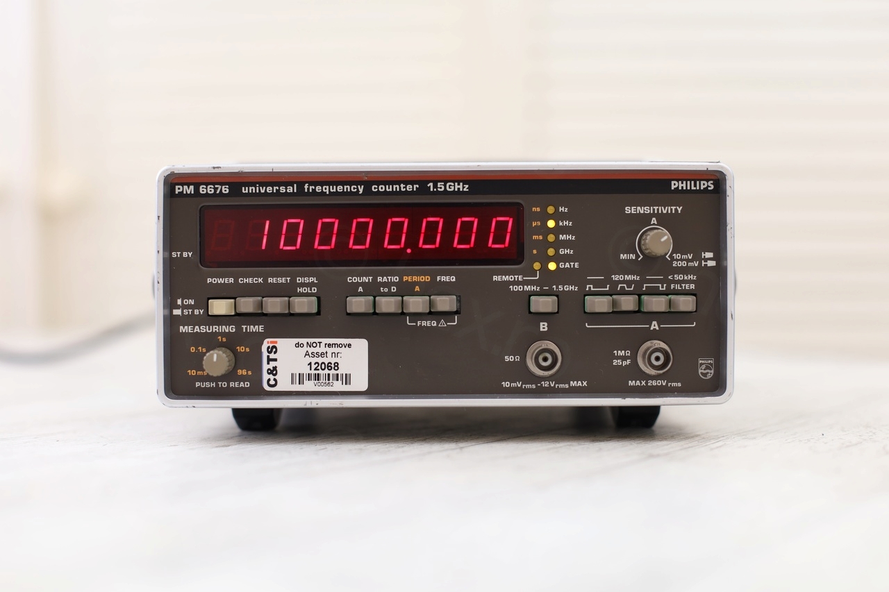
Here I am, trying to rescue this Philips PM-6676 Frequency Counter and keep the legacy going.
Table of Contents
- Overview
- Evaluation and Initial Troubleshooting
- Locating the short
- Replacing the shorted ROE Capacitor
- Replacing the thermal fuse
- Testing
- To do
- Update 1 – GPSDO has arrived!
- Update 2 – PM9679E seems stable (28 Jan 2023)
- Update 3 – Stable at 10000.0008 (26 March 2023)
- Update 4 – Stable at 10000.0008 but … (10 June 2023)
Overview
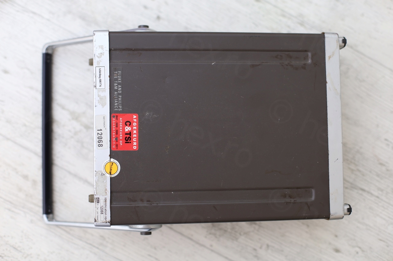
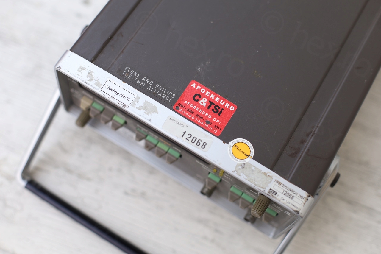
The device was rather dusty and had few stickers on it. One green, on the back, that is has passed a Safety Test in 2008, and another red on the top, that it was rejected in 2010. There are two identification numbers – as if it belonged to two different calibration laboratories ?
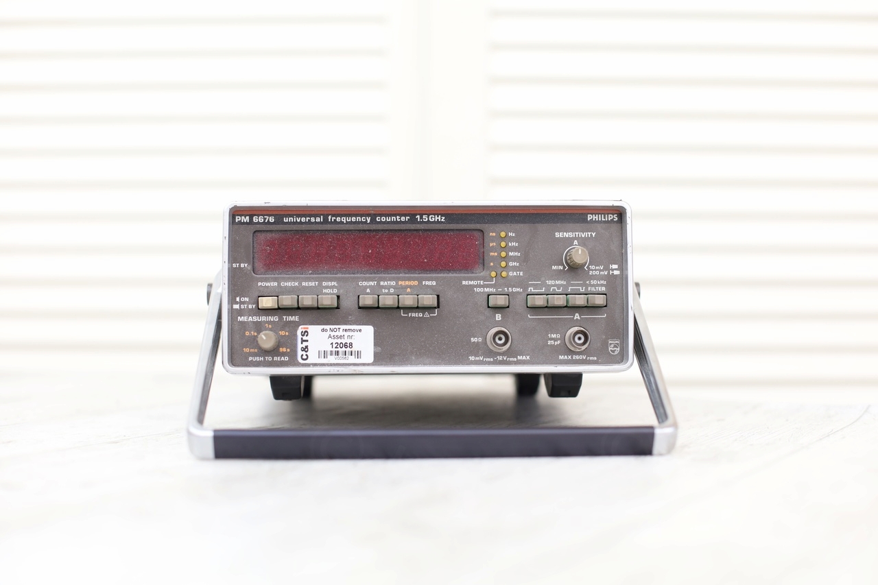


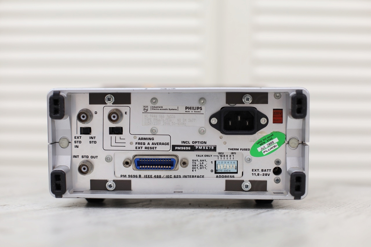
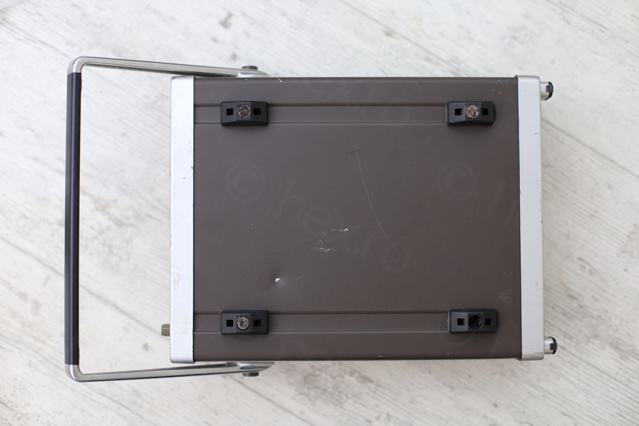
According to the information on the back, it comes with two options: PM9696B (IEEE 488 / IEC 625 Interface) and PM9679 (10MHz OCXO).
Evaluation and Initial Troubleshooting
I decided to try to power it up directly, see what happens. And surprise, nothing happens as you can see below:
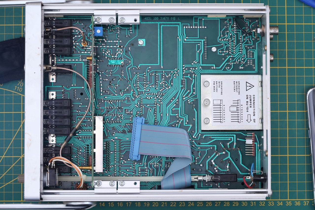
I decided to take it apart and have a look inside:
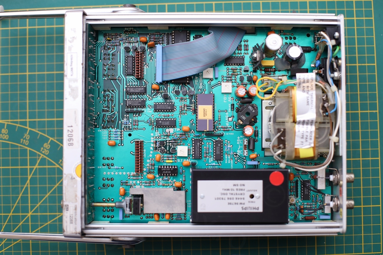


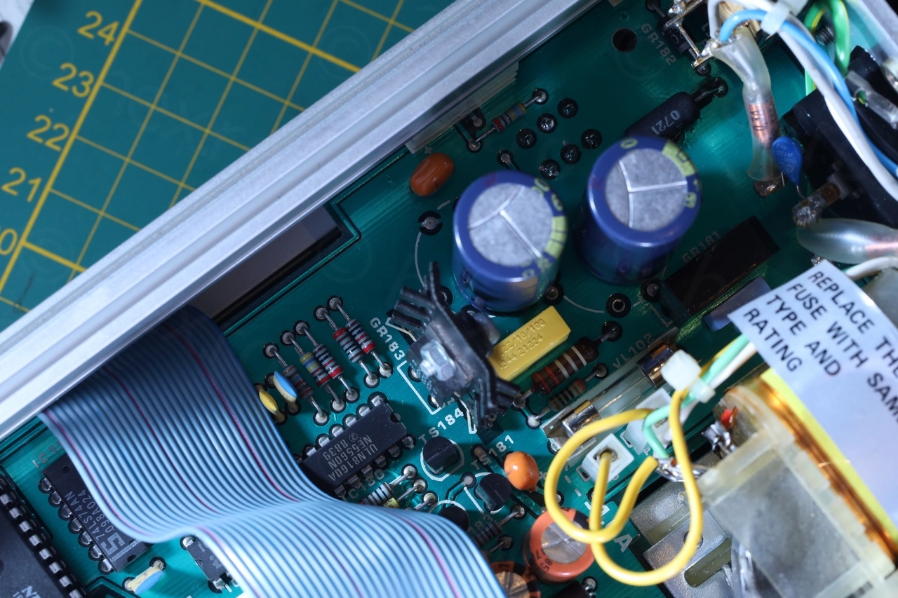
I found too many things at once:
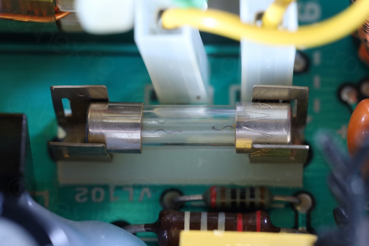
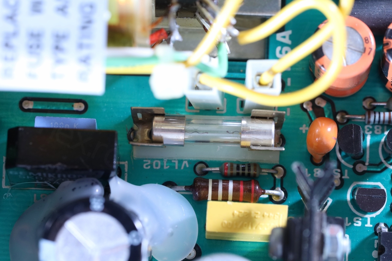
- Blown 1.6A fuse
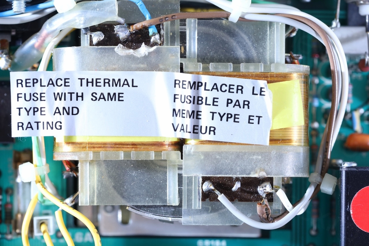
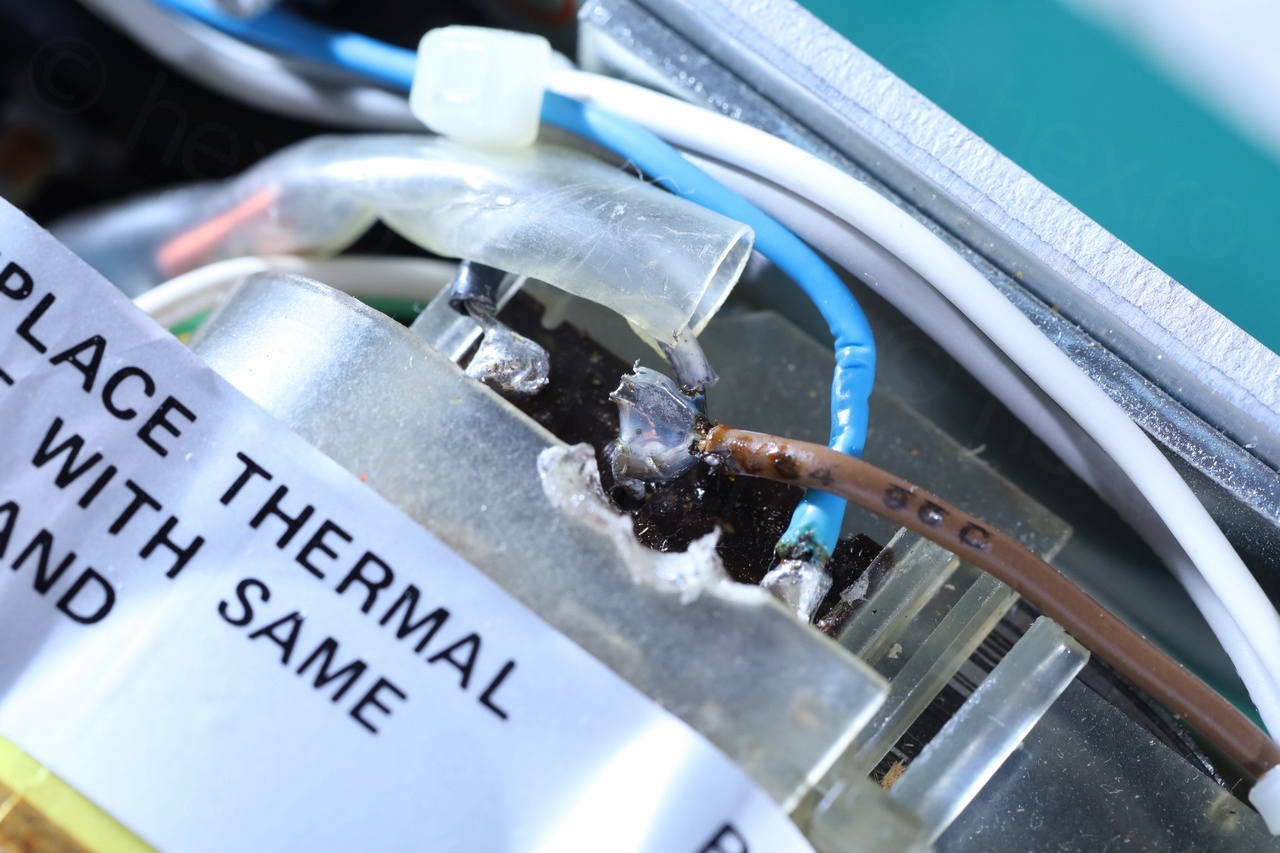
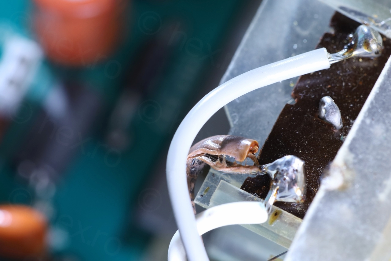
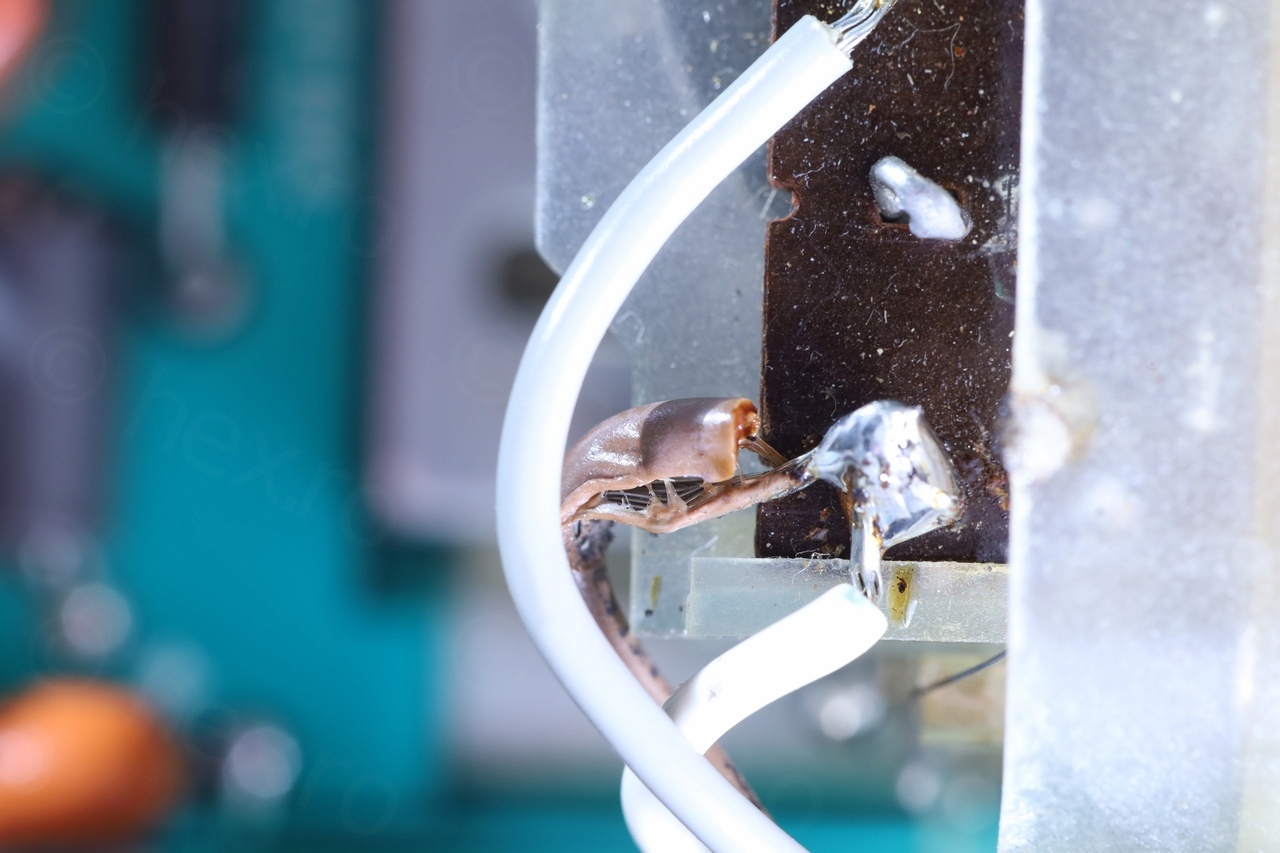
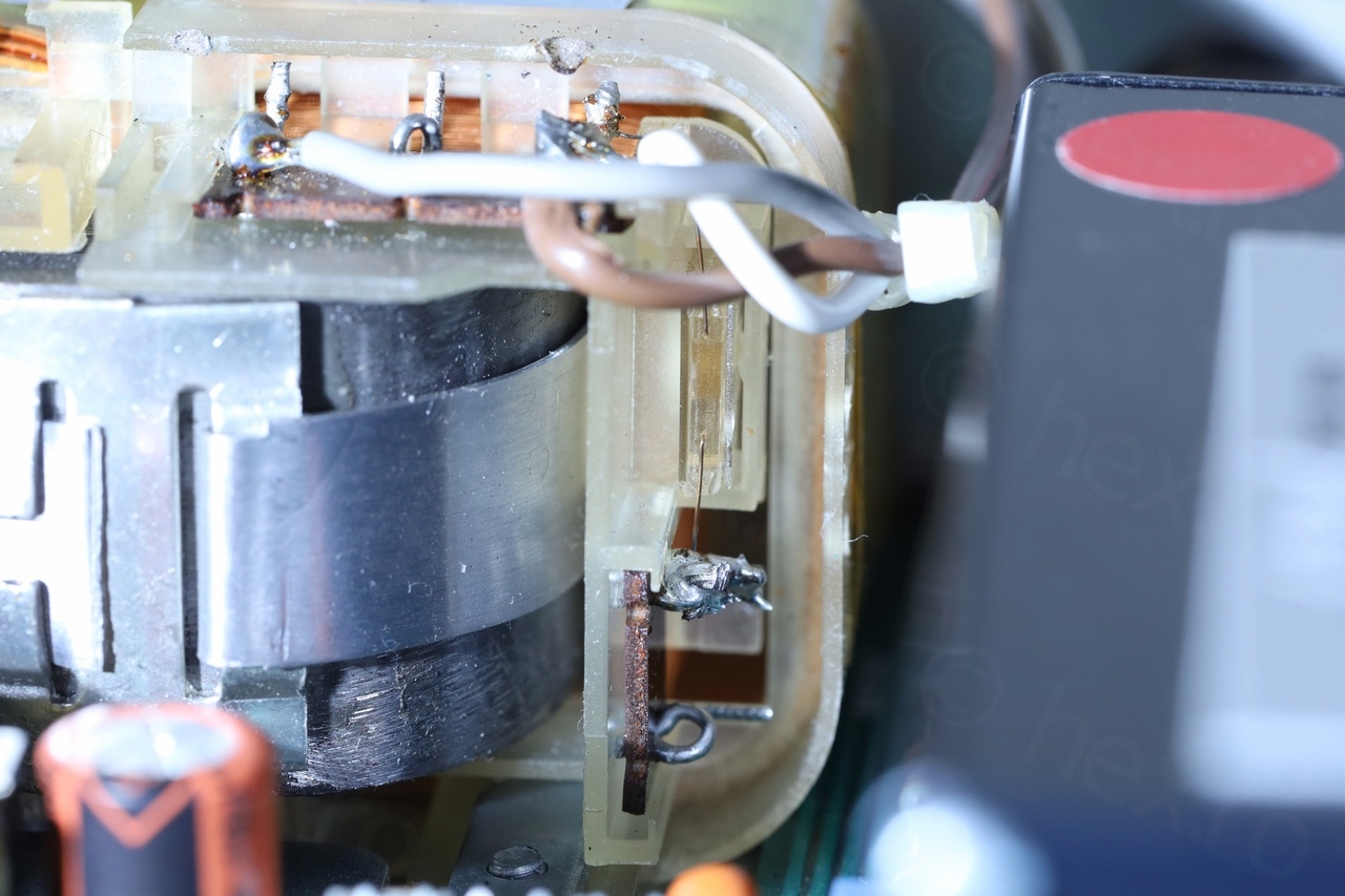
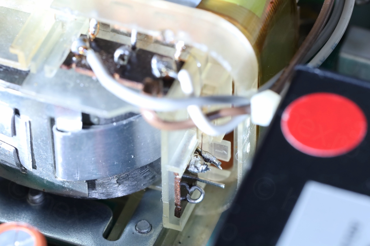
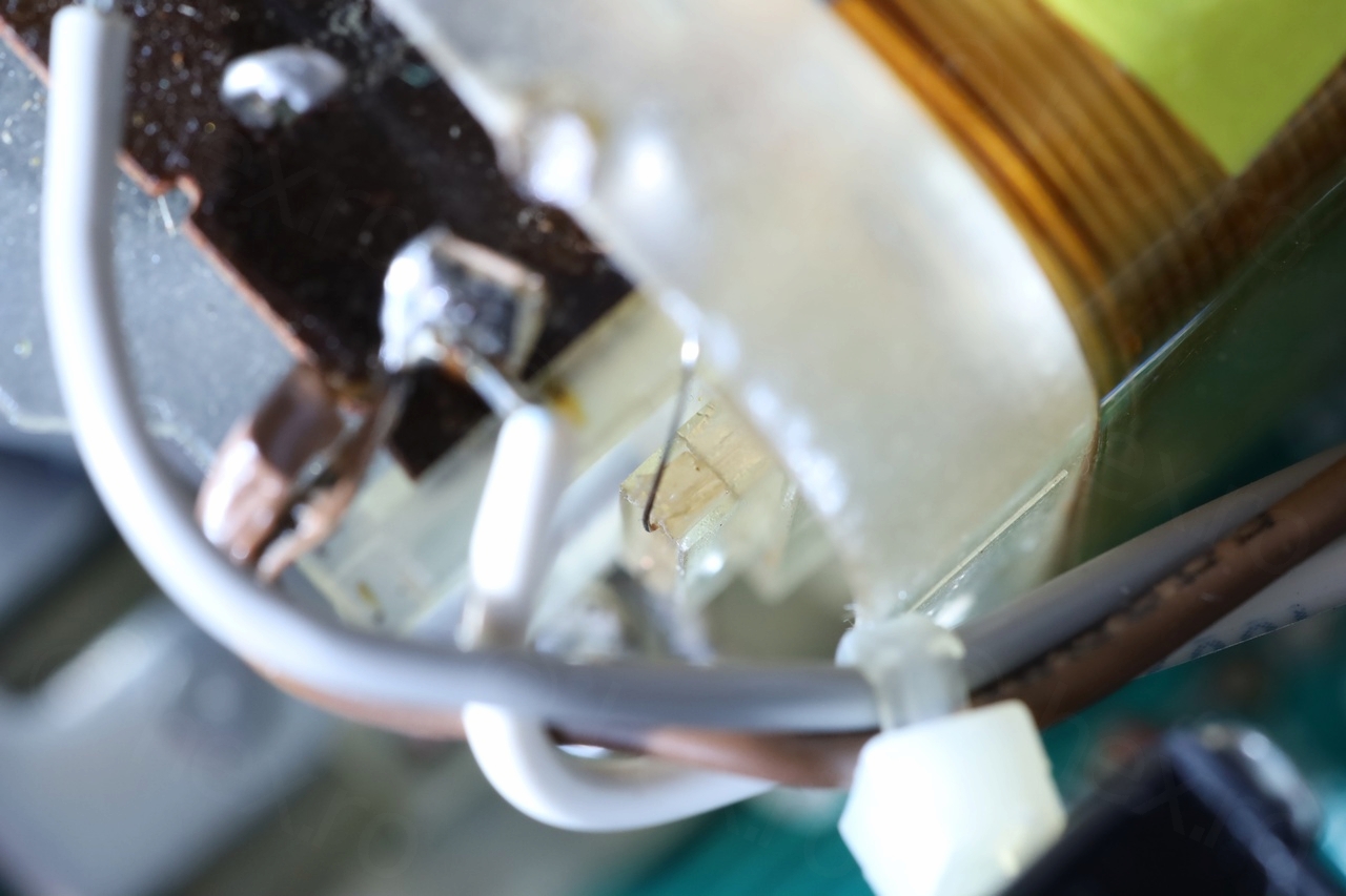
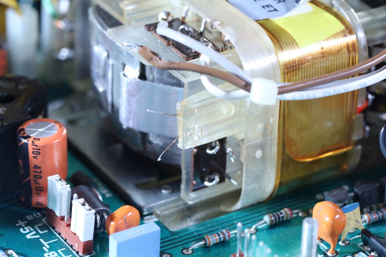
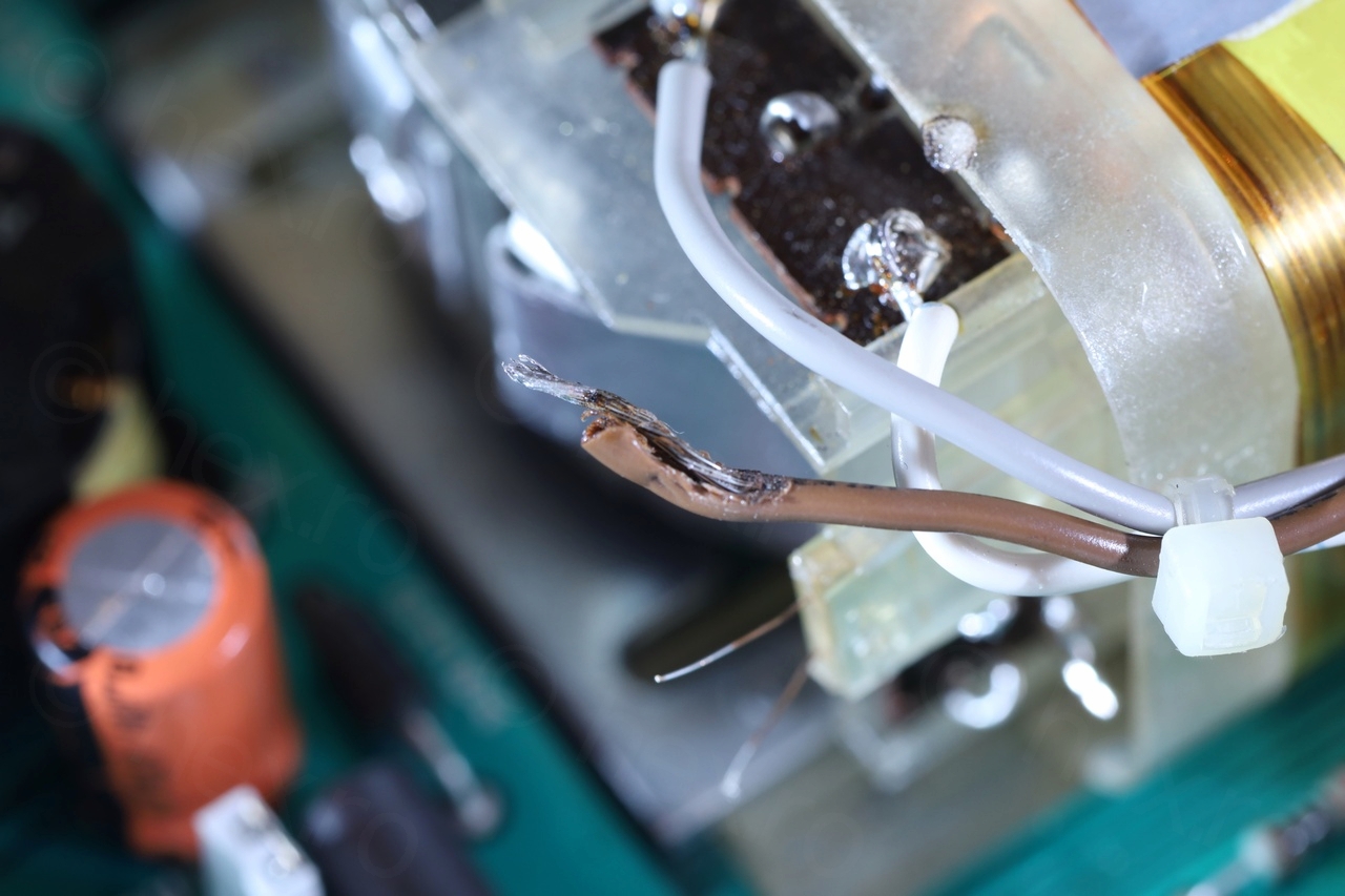
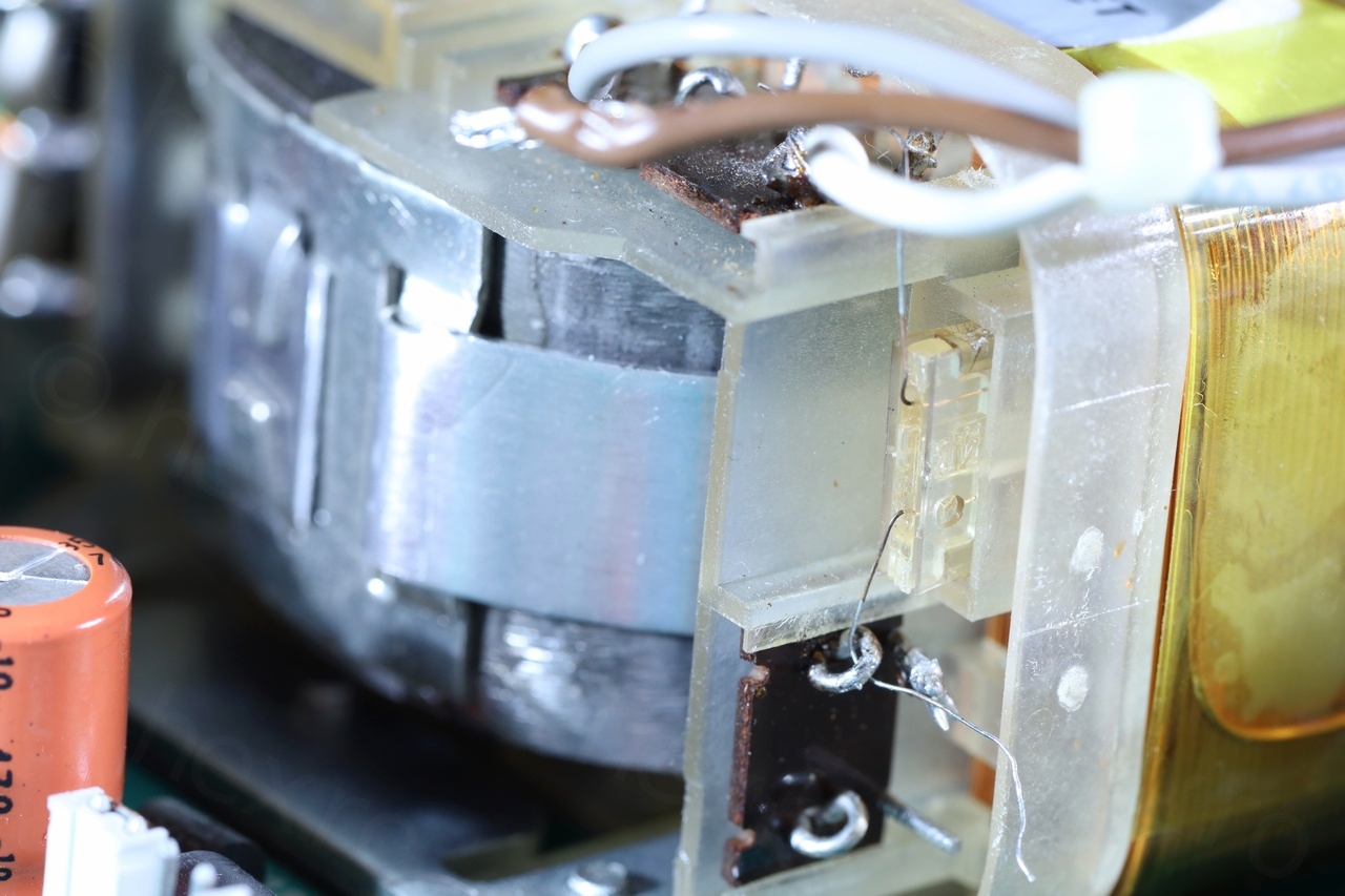
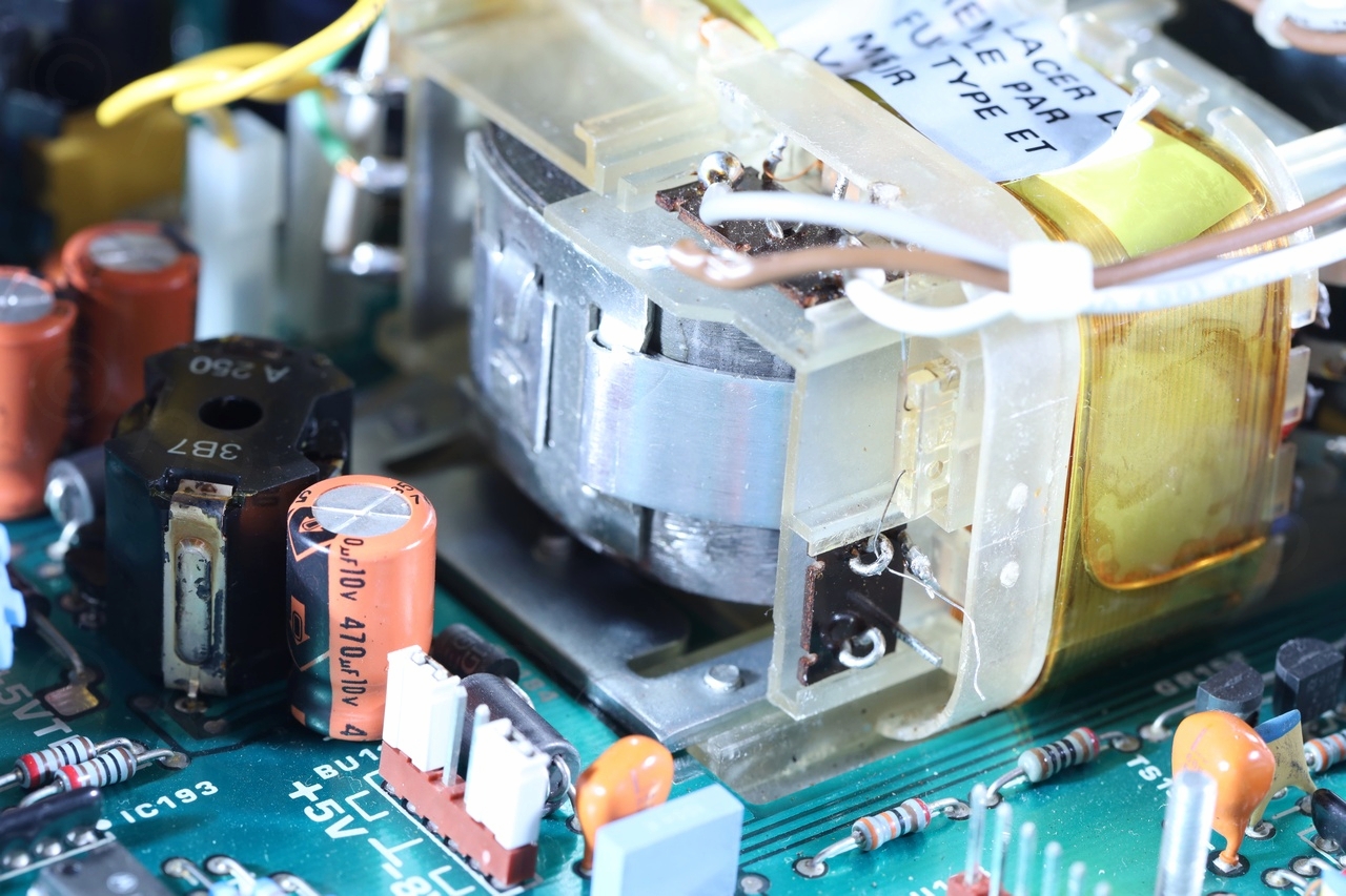
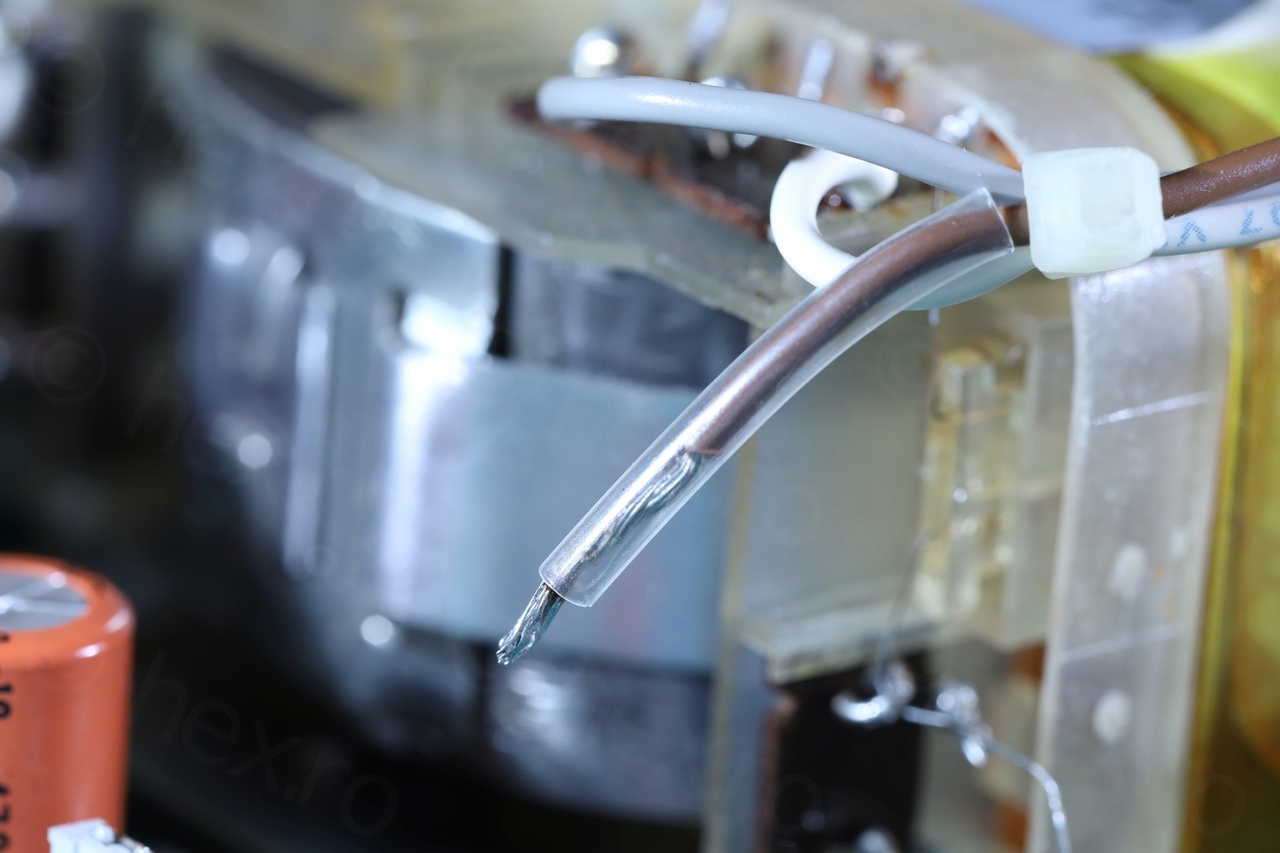
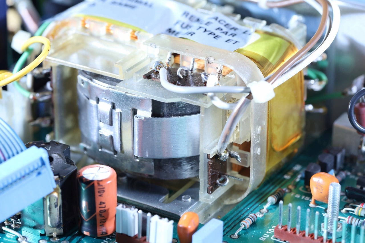
- Signs of previous repair attempts: circuit board scratches, transformer plastic was melted by what looked like a soldering gun, melted sheath of the Brown wire
- One big filter capacitor looked newer than the other one. Existing one was a ROE capacitor, the newer one was a Jamicon.
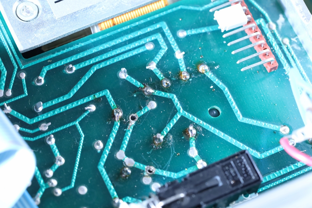
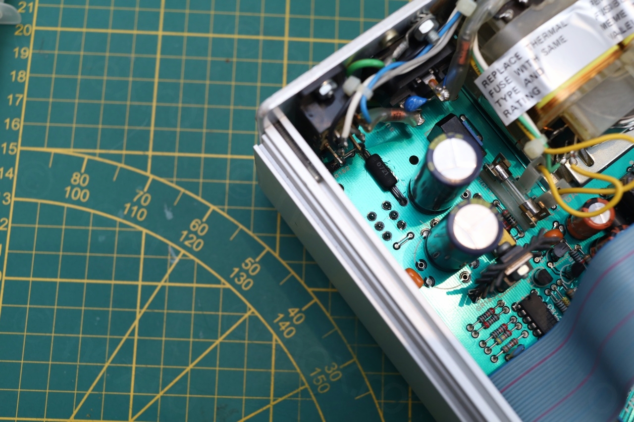
I took out the bottom board (the GPIB interface) and had a look underneath too – to find more signs of repair attempts: soldering that looks different than factory, the bridge rectifier also seems re-soldered (thus probably replaced). Also some unpopulated holes:
Conclusion is that something dramatic happened in the Power Supply area. By this time I had already downloaded the service manual and identified the PS schematics.
Studying the schematic, it seems that applying power via the external battery plug (confirmed center positive with the continuity meter) -> bypasses all transformer circuitry and arrives to a diode and then to the blown fuse.
Decided to replace the fuse (1.6A, fast – required by manual) and power the circuit with 14V via the battery plug, but with current limited to 0.6A. And surprise, even with the device off (power button NOT pressed), the desk bench power supply goes into protection mode maxing out at 0.6A. Hmmmm.
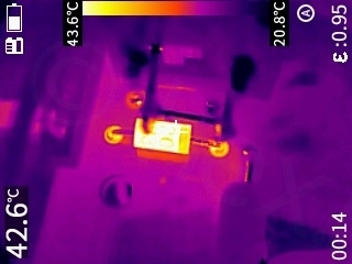
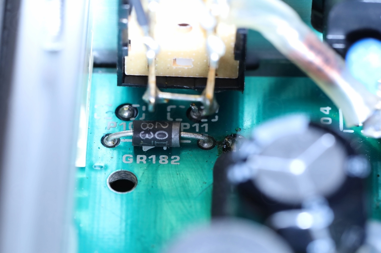
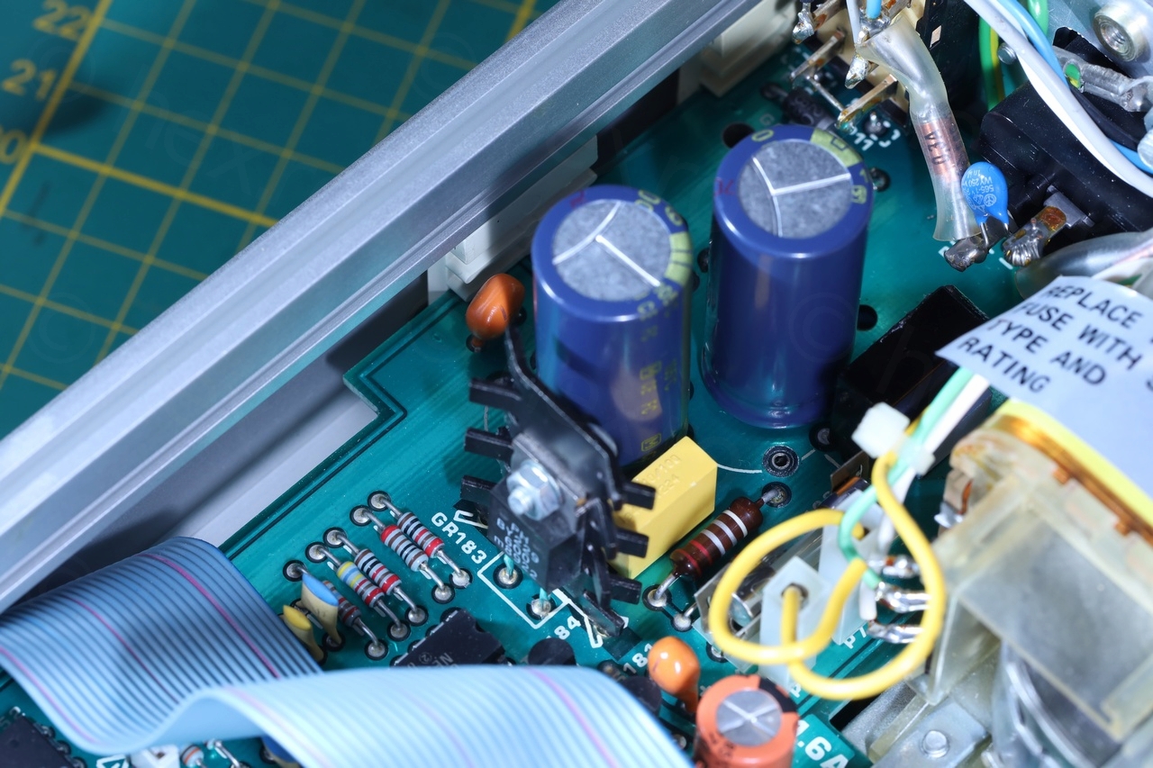
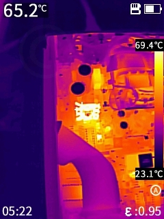
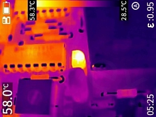
Checking with the thermal camera -> GR182 gets hot instantly:
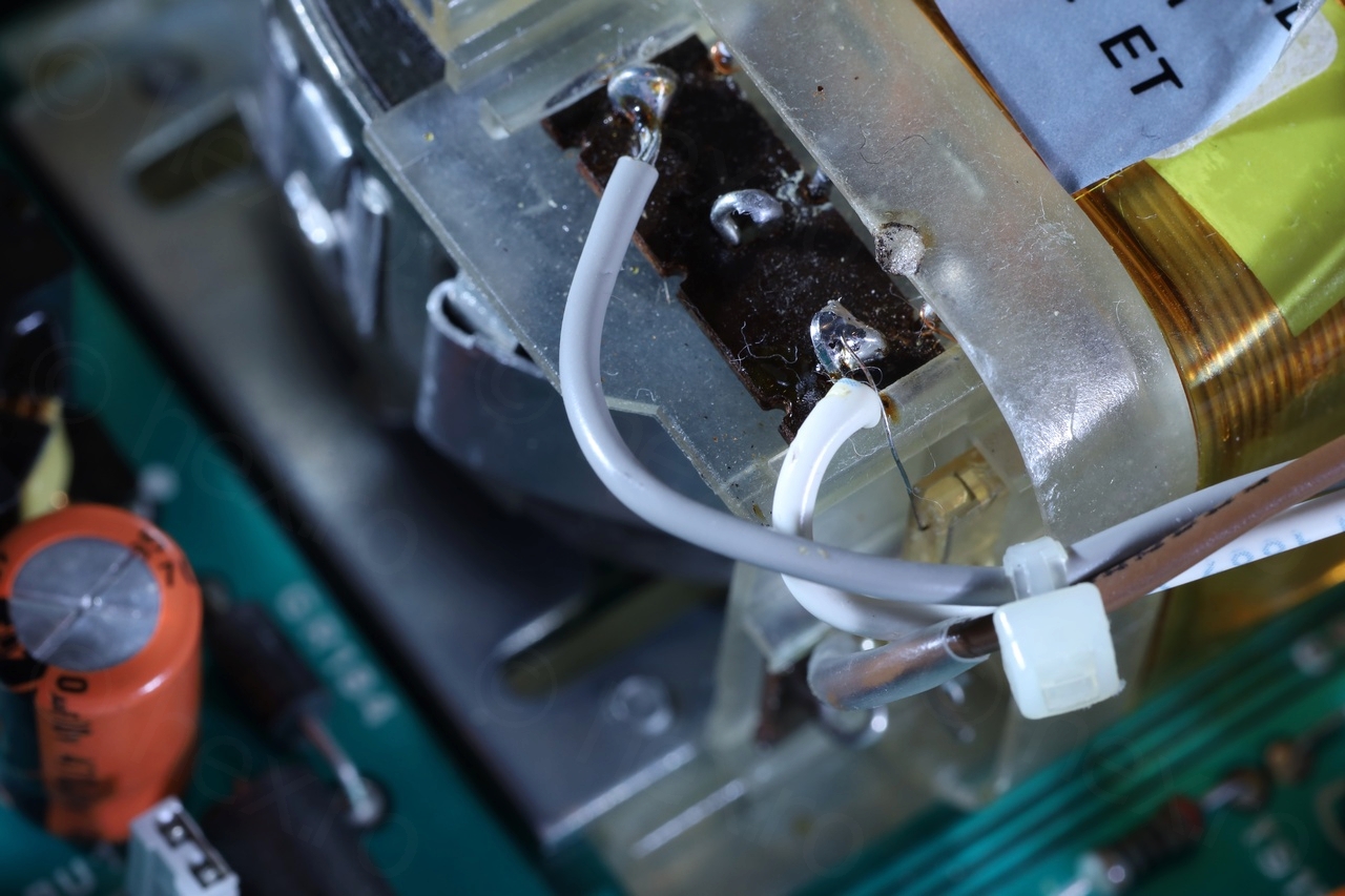
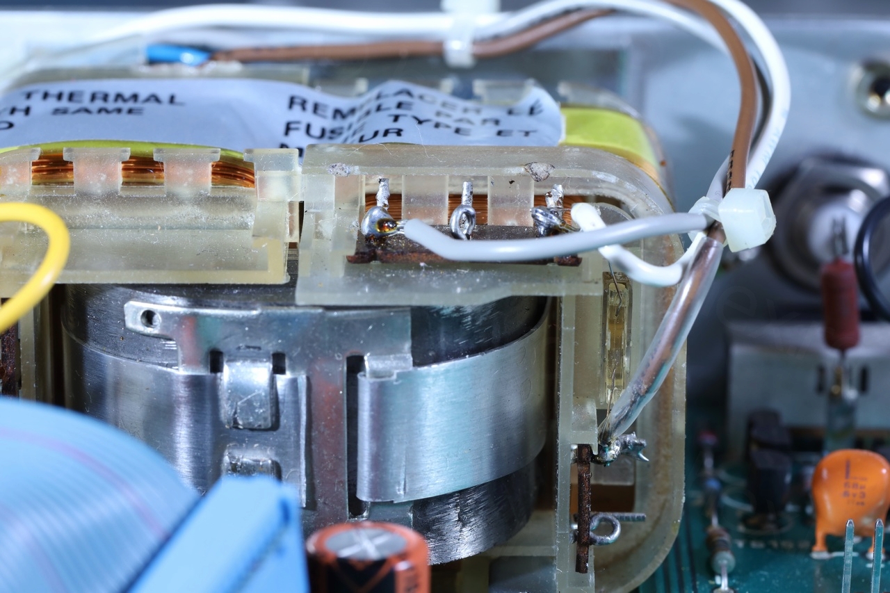
By this time, I was already more familiar with the schematic. I have realized that the Brown cable was not where it was supposed to be. It was moved from position 12 to position 1, to bypass the VL101 thermal fuse that is part of the transformer body. This fuse too was blown, and somebody moved the Brown cable, physically by-passing it. This also explains why the Brown wire was melted. More proofs of attempted repairs.
Locating the short
The first step would be to find the short. Since the diode was getting hot, I took the fuse away, since the short could have been before or after the fuse. Either inside the bridge rectifier and the shorted diode (to the ‘left’ of the fuse), or somewhere after the fuse. With the fuse removed, the my Desk Bench Power Supply supply did not get into protection mode! The short was definitively after the fuse.
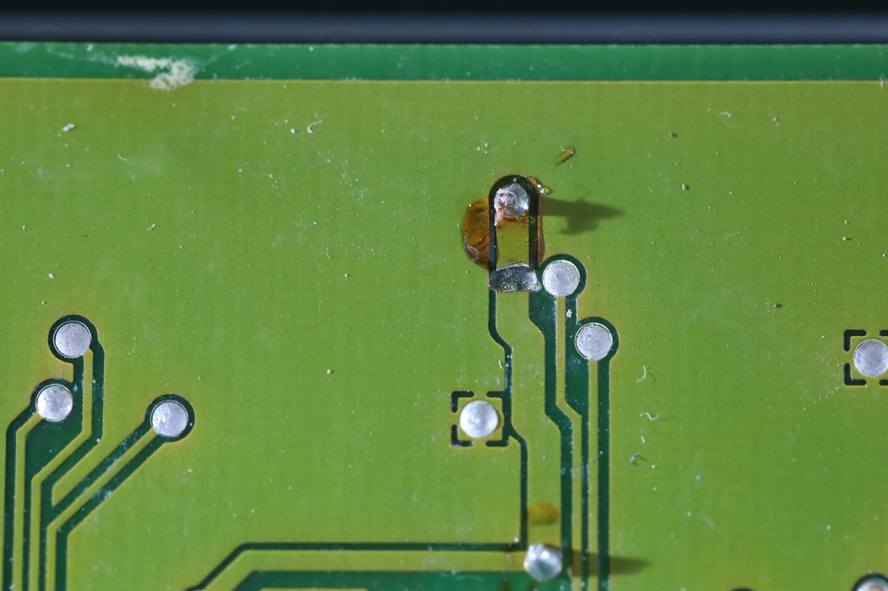
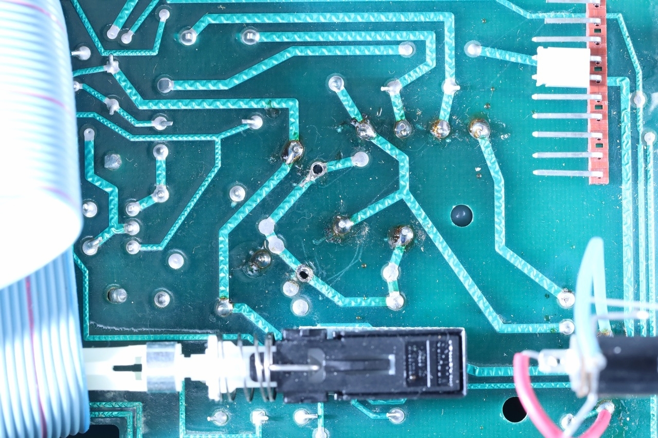
The point with the red arrow is shorted to ground:
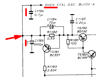
Since the Oven XTAL Osc. BU103:4 (the 10Mhz OCXO) can be removed, I took it out. Short persisted.
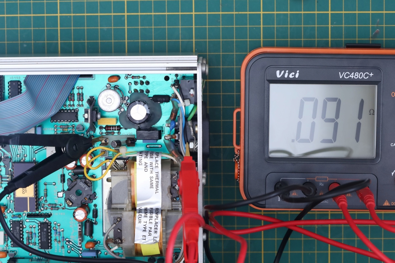
Since R1182 is small at 0.33Ω, I did not know if the short is after it, or before it. Fluke 116 would report it as shorted (too little resistance) so I took out the milliohm meter to measure it. It measured 0.25Ω in circuit. But since the resistance from the red arrow node to ground was 0.091Ω, it means the short is before R1182!
Thus, one of the C1194 or C1183 is shorted (since the OCXO was out), but which one ?!
From the Red Arrow to GND there was a resistance of 0.091Ω, however, C1183 was measuring 0.032Ω to ground, while the C1194 was measuring 0.092Ω to ground. C1194 measured higher since, I figured, it is the resistance of C1183 to ground + the trace resistance to C1194. C1183 was the culprit!
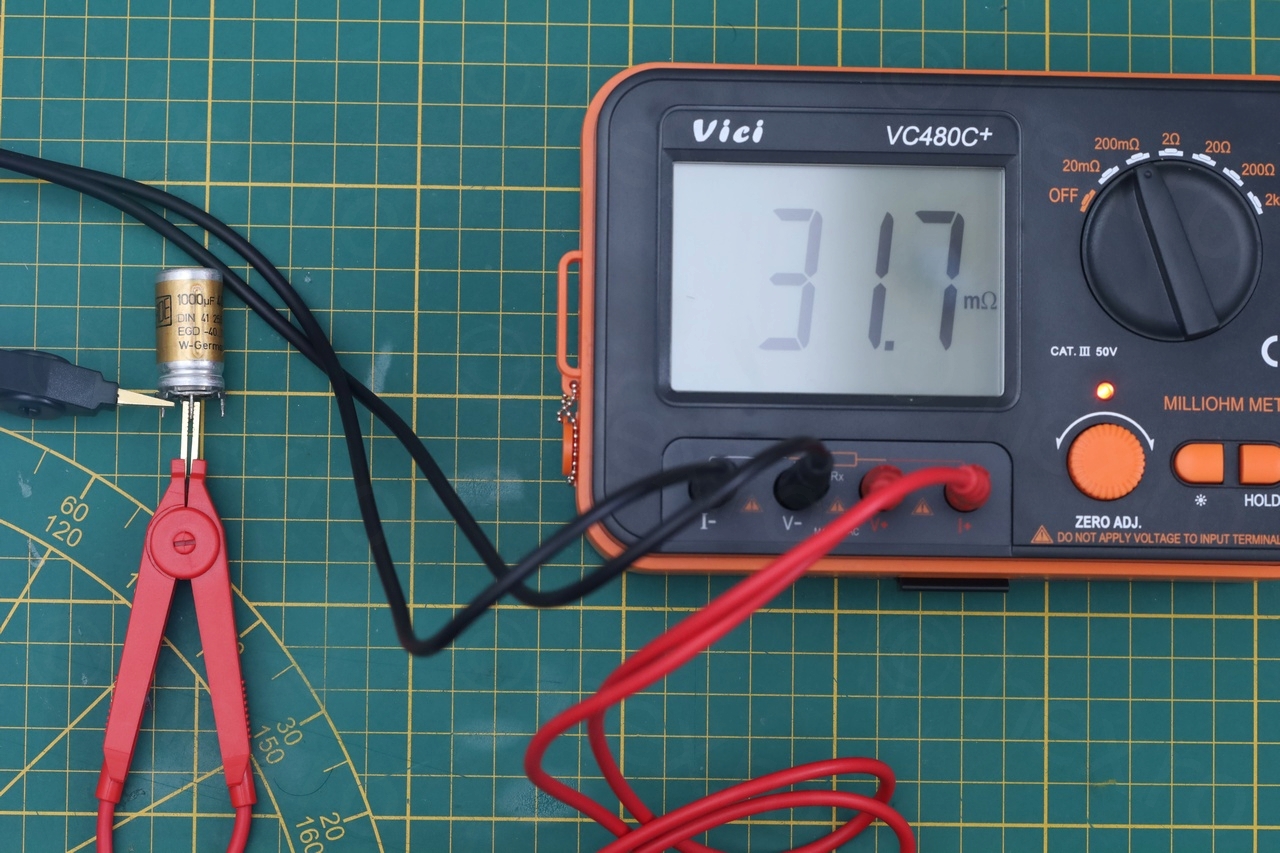
C1183 was in fact the ROE Capacitor being short circuited. Most likely the previous one (now a Jamico in its place) was a ROE too, with its 4 pins (3 are ground, and center one is positive). That’s why there were the unpopulated holes on the circuit board.
I decided to swap them both, and ordered 2 Panasonics, 1000µ at 63V (even if the existing ROE cap and the Jamicon were 1000uF @ 40V).
Replacing the shorted ROE Capacitor
Remove the second ROE Capacitor was not easy, due to one of its pins hidden under the On/Off plastic rod that is connecting the front panel down to the actual button switch on the back of the board. It was easier for me to de-solder all of the 6 pins of the switch instead of messing with the rod trying to detach it from the button.

The two Panasonic caps are rated at 63V:

The device started working after this. One thing to note – it does not start without the OCXO installed (I’ve first tried powering it without the OCXO, which was out to allow me to narrow down the short). But only the stand-by LED comes on, no other reaction from the buttons without the OXCO.
Replacing the thermal fuse
By this time, I had already tested the device with Mains power and it worked. So the transformer survived the initial incident, most likely due to the Thermal Fuse.
The manual asks for 4822 252 20007 thermal fuse. I could not find anything related to it at first. I considered a lot of options on how to adapt / insert a modern fuse. But it felt bad to bodge something up, not to mention that I had no idea of the specifications of the original one! While looking for possible specifications, I landed on a single thread on vintage-radio.net which opened my eyes to the situation, a real AHA! moment. I am grateful for the members there that commented and offered catalog information and specifications, along with a huge hint:
Philips has been using the same thermal fuse in many many devices of the era. If I could get my hand on an old Philips that has a Mains connection, I may be lucky enough to find a thermal fuse and just swap them.
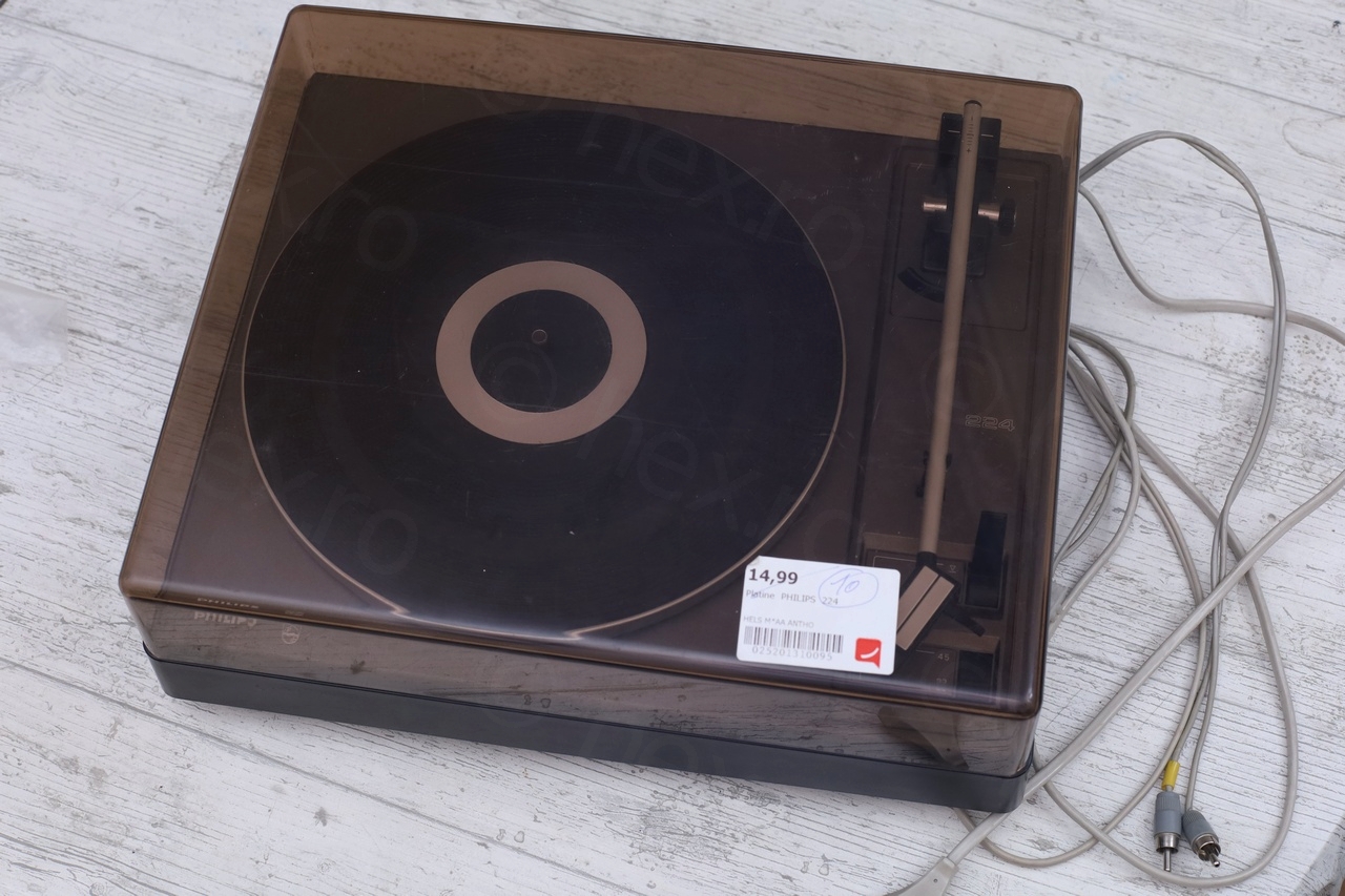
And as luck would have it, I did find one! In one of the local second hand shops I spotted a beaten down old Philips Turntable – model 22GA224. I whipped out the phone to try to locate the service manual for it, but was only able to find the one for 22GA222 model. What was the listing showing for the “Trafo fuse” ? 4822 252 20007! Without a stylus and with some bodged wires, the shop was even kind enough to offer a discount. All the way home I wished that the 224 model was very similar.
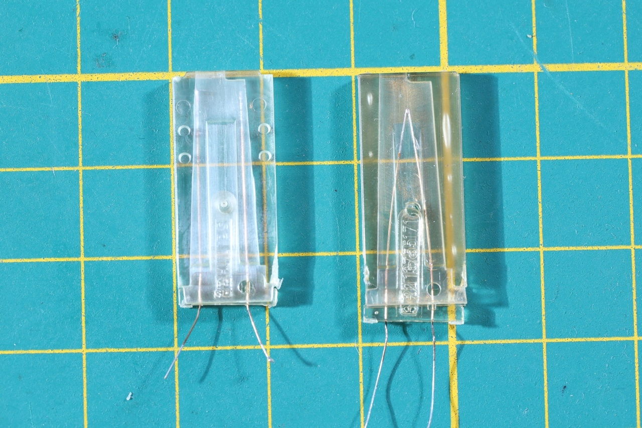
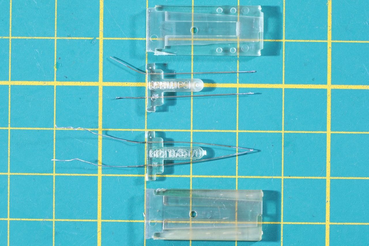
Taking it apart was easy. I could not savage the transformer, had to break it apart to be able to extract the fuse – it was buried too deep.
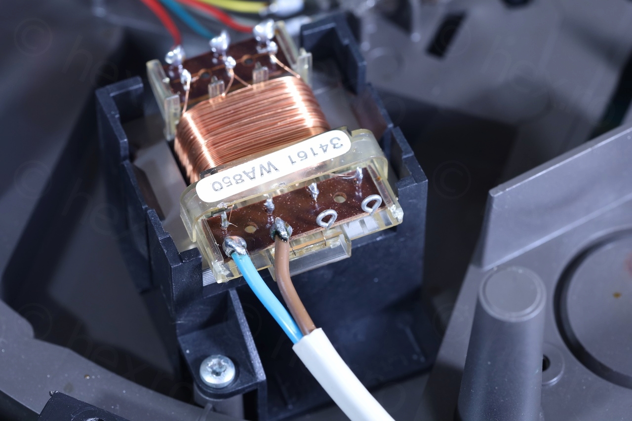
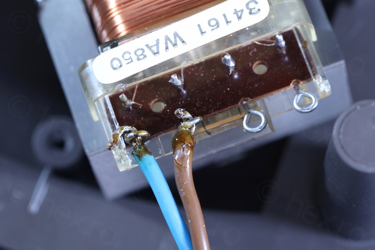
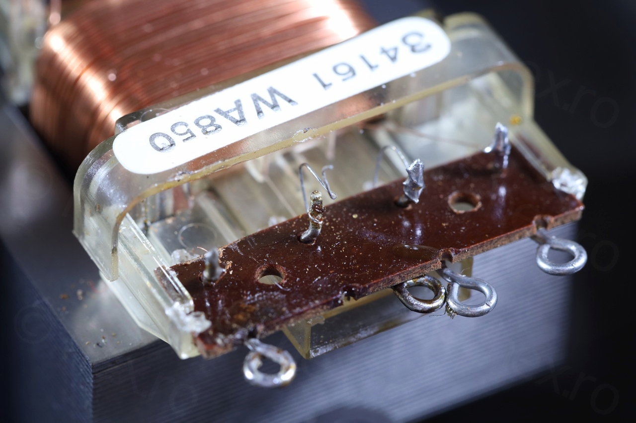


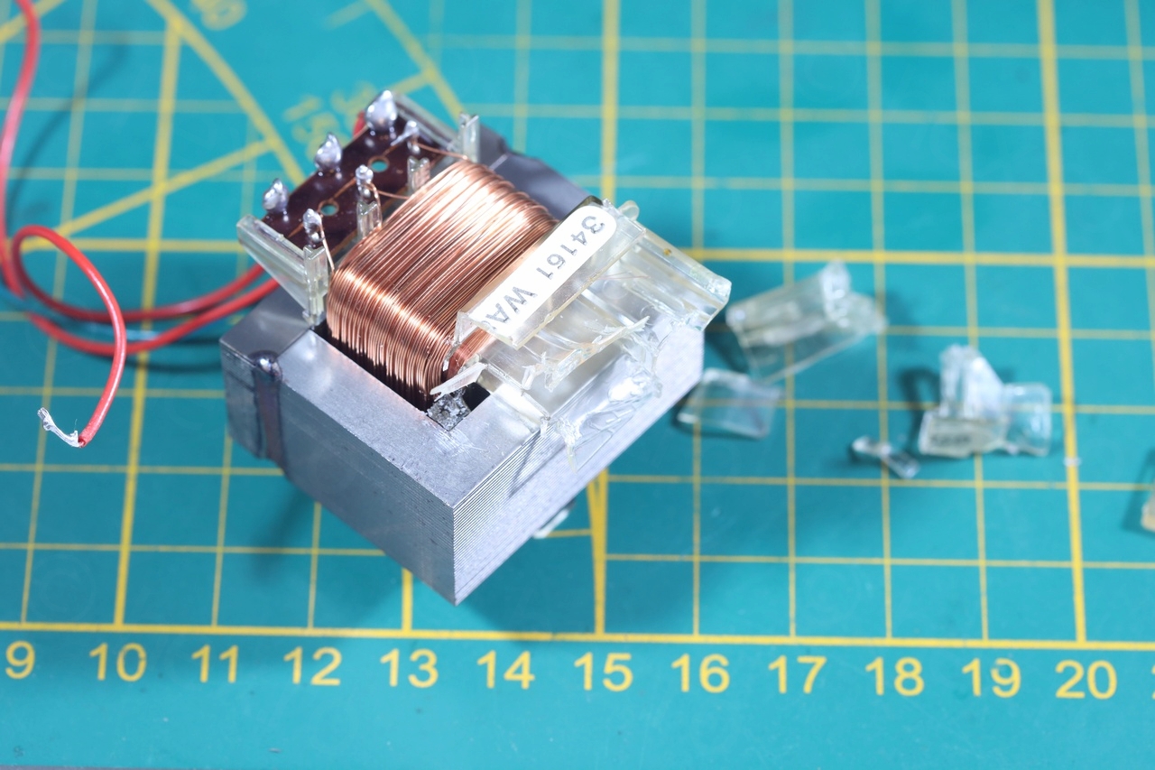
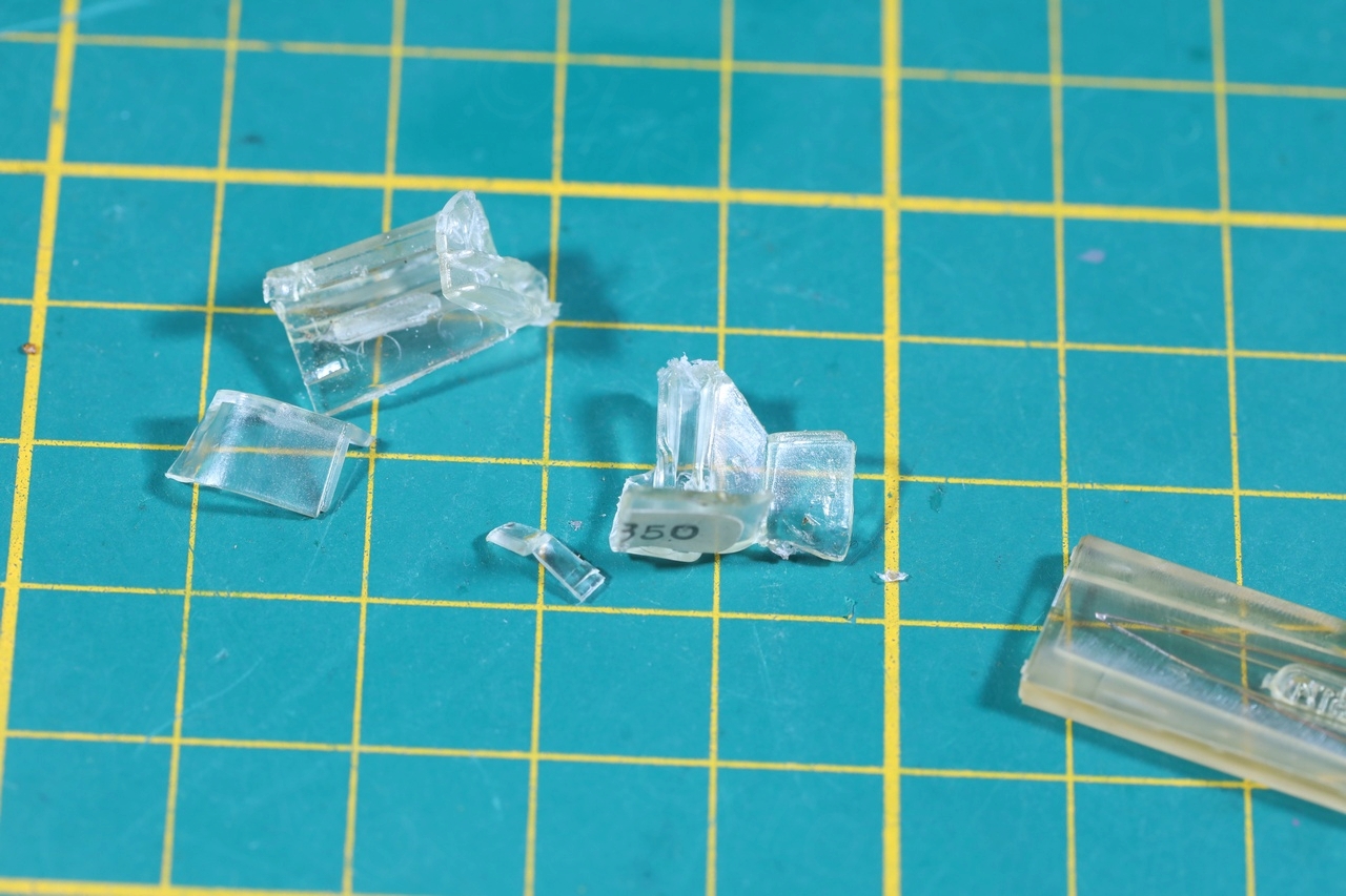
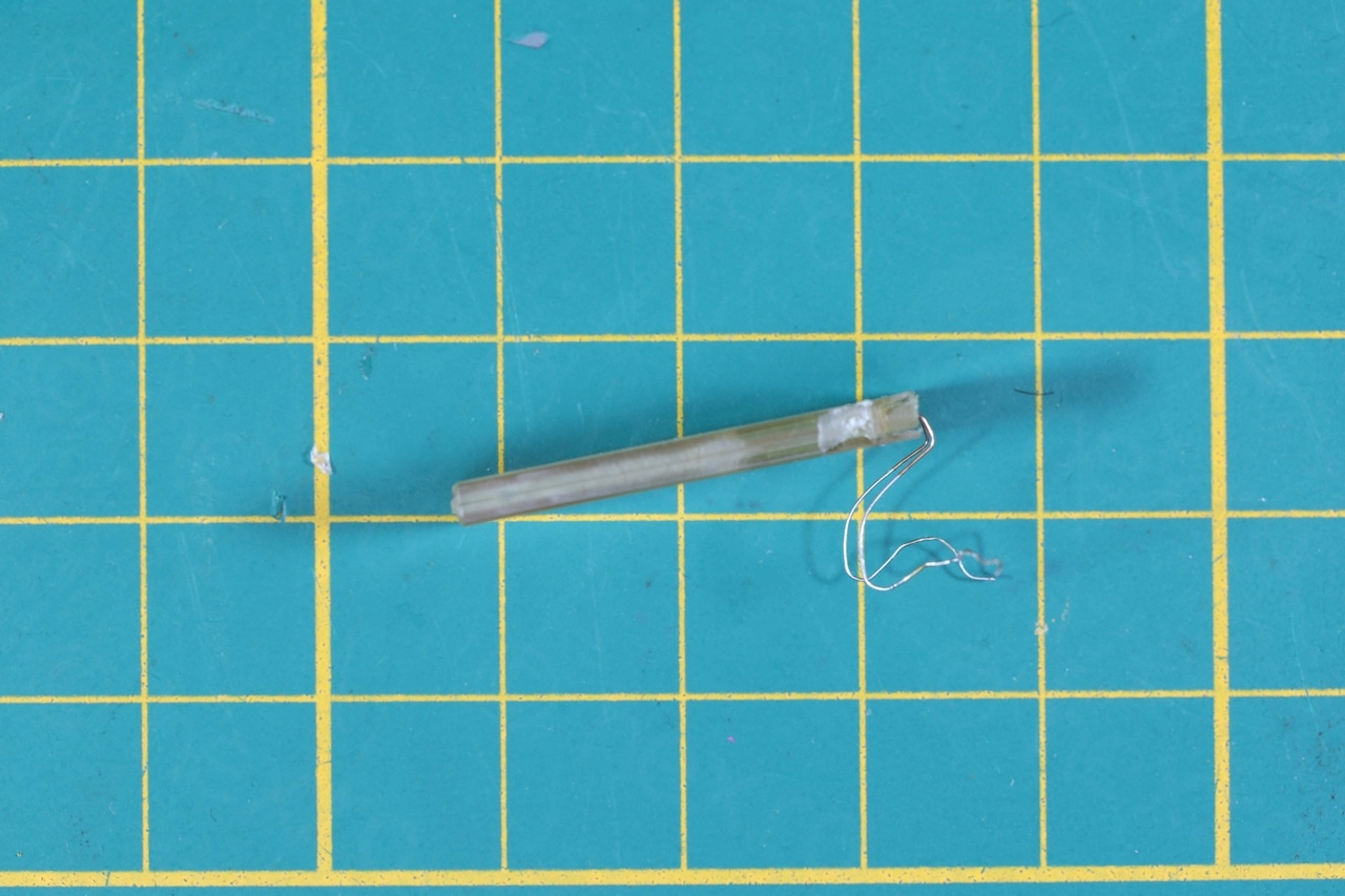

Luckily, this thermal fuse had long enough wires and I payed a lot of attention not break them and salvage them intact. The fuse in the Philips PM-6676 was much easier to get out. I soldered the replacement on the outside binding posts – since I did not have easy access under the plastic shroud of the transformer to access the initial binding post.

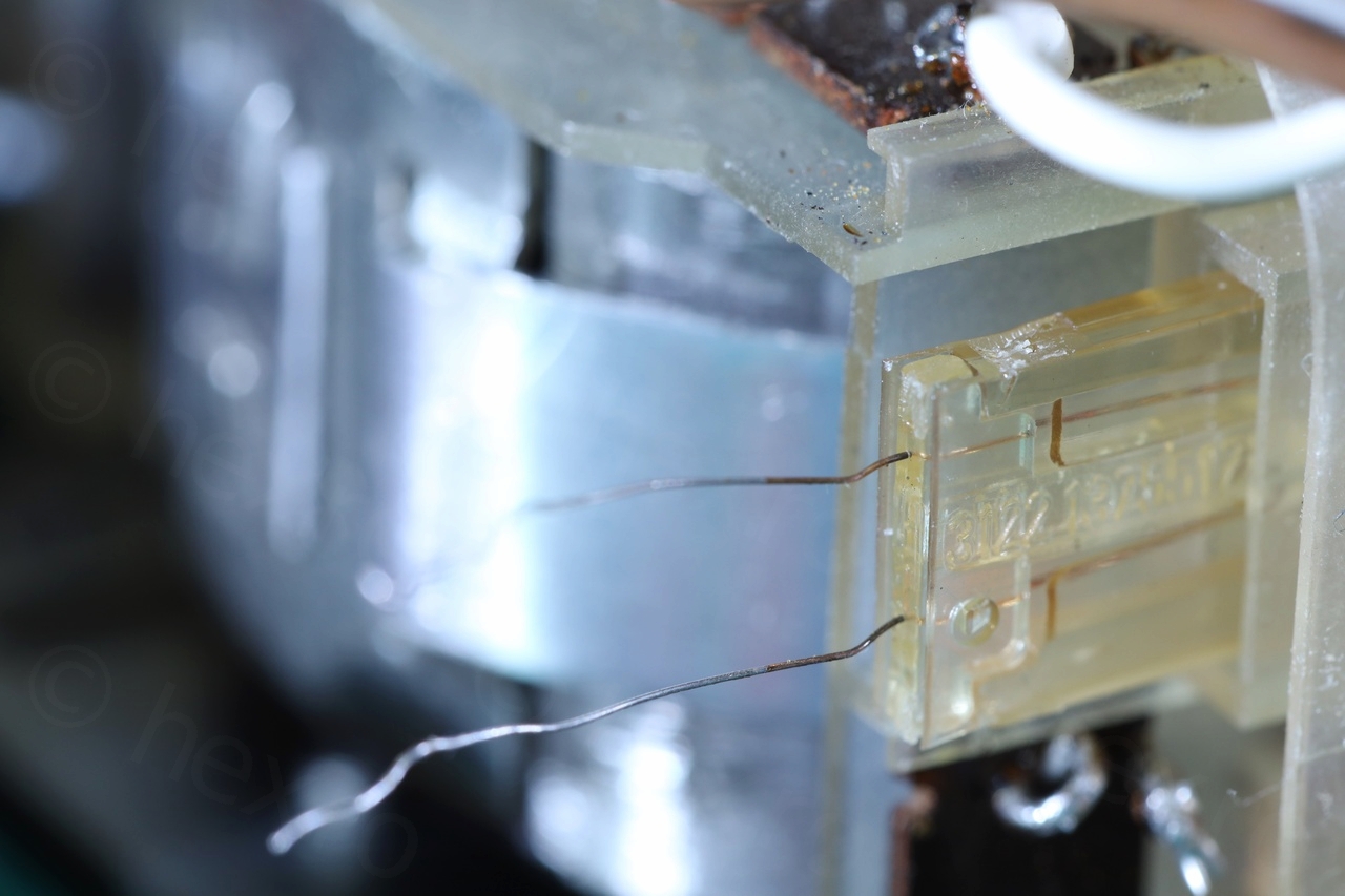

The Brown wire could now be moved to its initial position, but not before I inserted an isolating transparent sheath to insulate its damaged one:

It was already working, only now it felt … fixed.
Testing
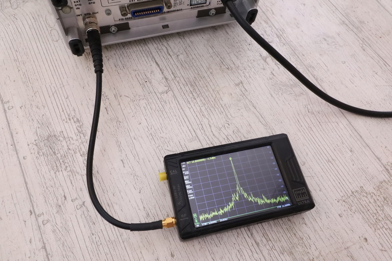
Since I don’t have a GPSDO – thus, no accurate 10MHz reference, the next best thing after doing a self check was to use the TinySA Ultra Spectrum Analyzer. Both to generate some high frequency signals, as well as checking the internal reference 10MHz reference on the “INT STD OUT” connector on the back of the device.
Self checks:
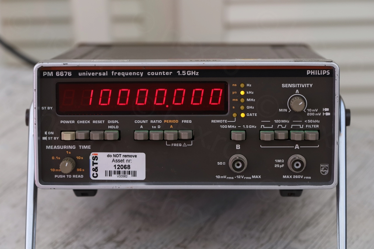
Second, checking the “INT STD OUT” 10MHz output with TinySA Ultra. It reports “10.00000MHz” in Spectrum Analyzer mode – I was impressed:

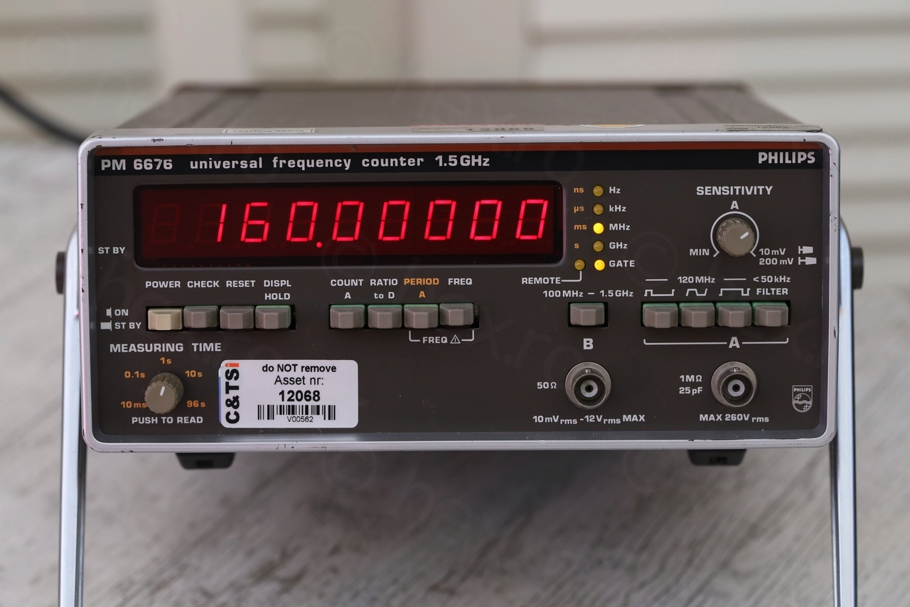
Then, generating few frequencies with TinySA Ultra as “Signal Generator” with the Output set to “Highest accuracy”:
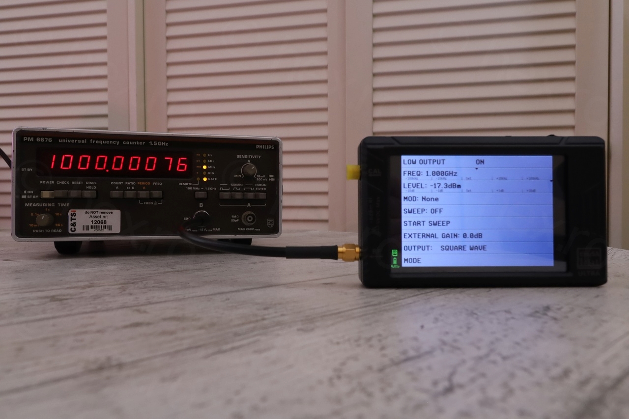
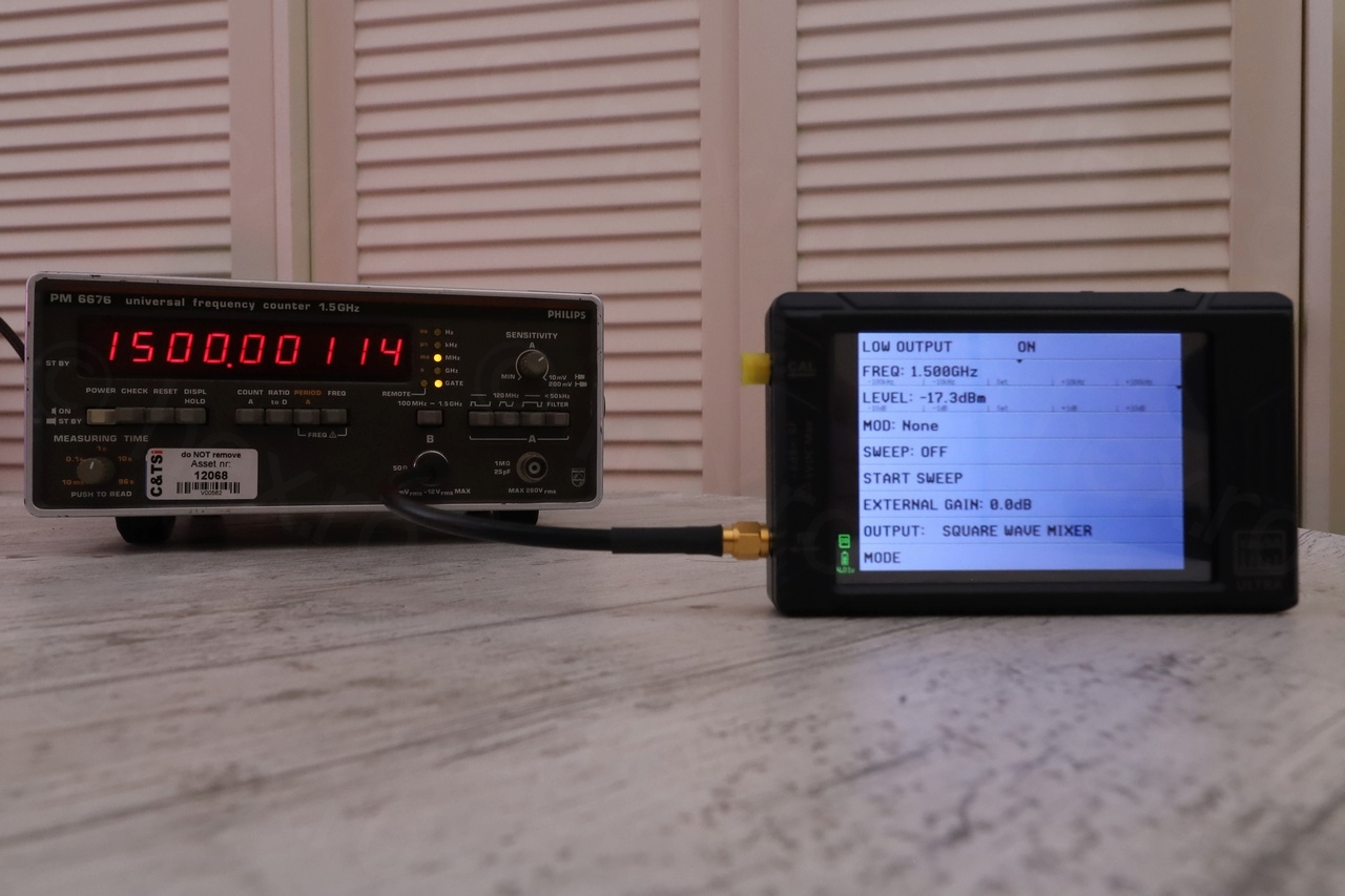


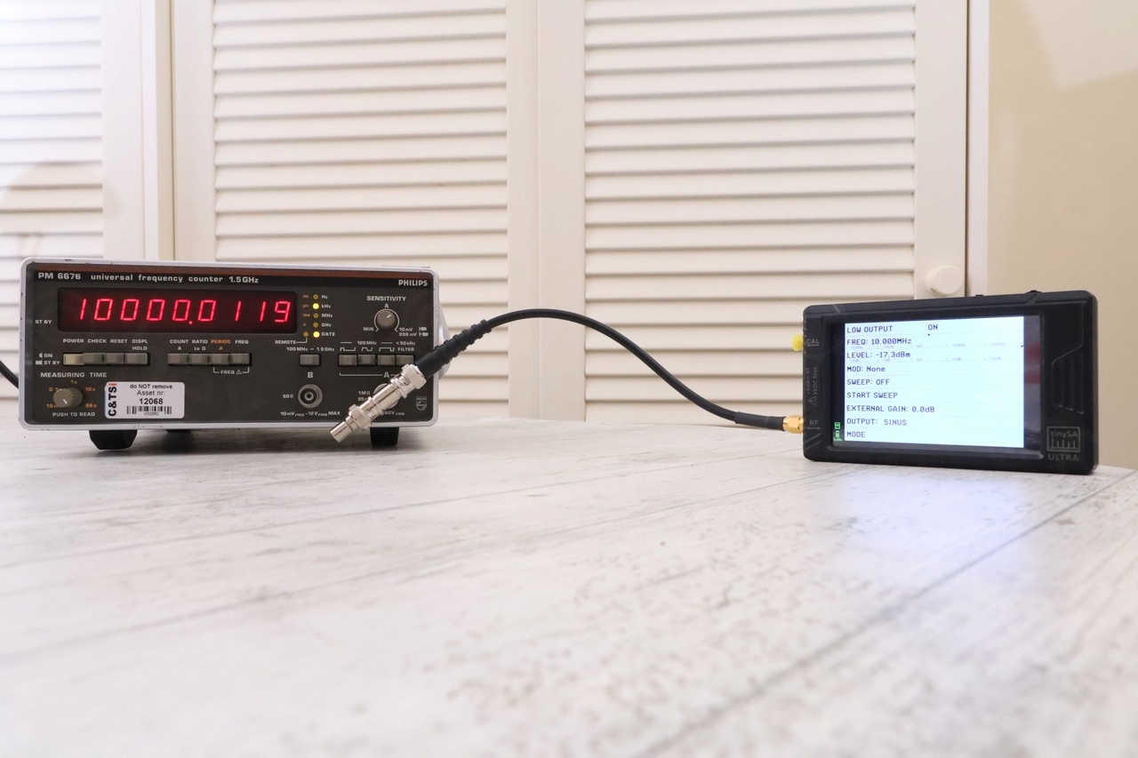
Without a GPSDO it is hard to say which one is more correct – but both are good.
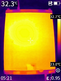
Some more infrared photos (room at 22C, Philips uptime was more than 1h):

To do
There are still few remaining things to do:
- Not sure if I should silicone the capacitors down. Is not like I’m going to use the device in a portable mode, to transport daily or submit it to vibrations. I should probably test how easy is to remove the silicone once it sets, by using a pre-drilled circuit board with some test capacitors.
- There is a very informative video of the tear-down of a Philips PM-6672: EEVblog #265 – Philips PM6672 Timer Counter Teardown where an insulating plastic covers the high voltage area of the device:
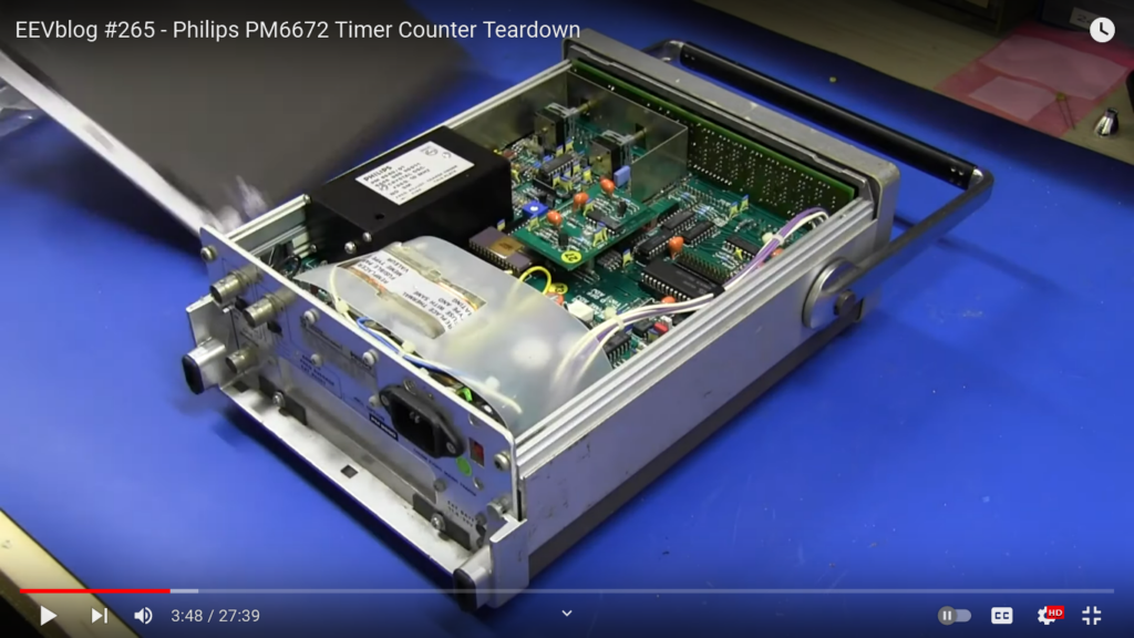
Unfortunately, I didn’t find one in my device. I kept thinking what would be the best to use as a replacement – but I have no plastic large enough that could serve as flame retardant / high voltage protection / cover. Some larger SMPSs (power bricks) that I took apart had a thick plastic wrapping the circuitry inside, I may reuse from one of those when I get my chance. For now, I just put the cover on.
Another interesting details in Dave’s video is that the transformer plastic (close to the White wire) appears to be melted too.
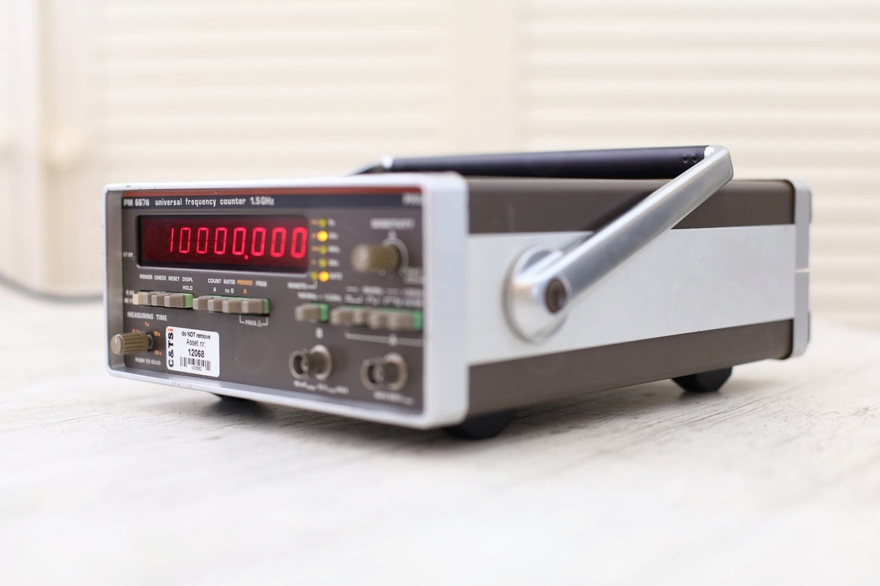
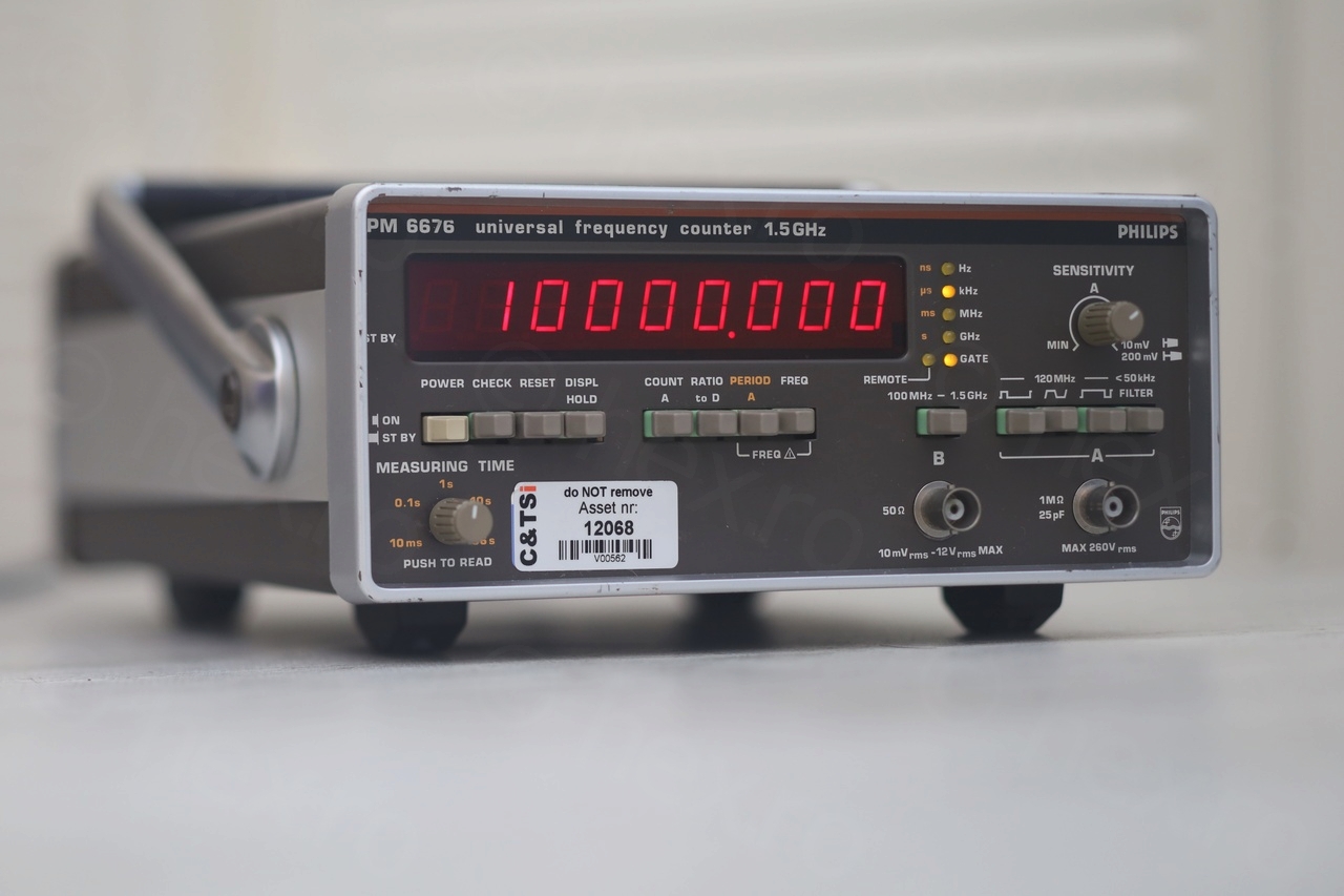
Some photos with the rescued device now cleaned:

Update 1 – GPSDO has arrived!
Since this Philips contained the Philips PM-9679 oscillator, I did some reading about ovenized crystal oscillators and their stability. And more reading about calibrating them. Long story short, I bought a GPSDO from DX-Patrol / Portugal and now I am having doubts if the this PM9679 works properly. Doubts are also because I lack experience working with frequency counters and I don’t know how to interpret its behavior.
According to the service manual, the PM-9679 achieves accuracy of < 1×10^-7 after 10 minutes, but when calibrating it, one must keep the device running for minimum 72h.
But what I observed is that after settling down, the counter was indicating 10000.0070 kHz, maybe 15 minutes after startup. Throughout the next 24h, the measured frequency decreased towards 10000.0045 kHz. After more than 72h, the value stabilized to 10000.0030 kHz. This means about 4kHz difference in > 3 days, which is a drop of 4 * 10^-7.
And this where it gets confusing, if less than 1×10^7 should be achieved in 10 minutes, why does it decrease with 4 * 10^-7 after 3 days ?
To add more to the confusion, there is a red sticker on the oven itself:
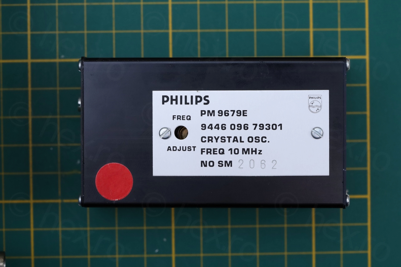
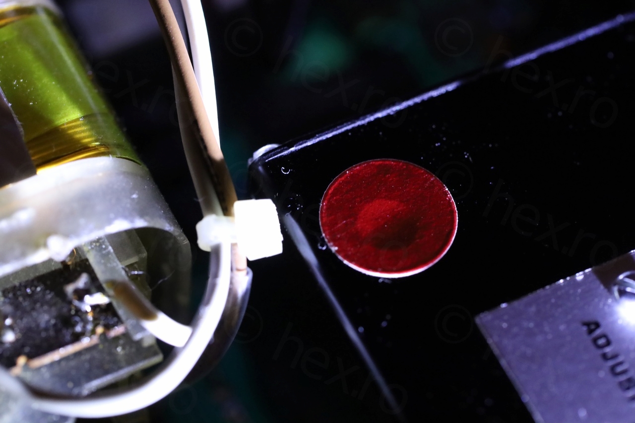
In EEVBlog video, the oven there did not have a red sticker. There seems to be a hole underneath this red sticker, but is not the one related to Frequency Adjust. Thus, is this red sticker a rejection mark from the calibration lab ?
I cannot find the schematics of the oven oscillator, except a mention by Philips that they can’t be serviced and you have to send them back to them. I guess this explains why no schematics …
The search was not fruitless though, I landed on a different topic on vintage-radio.net where the user dinkydi mentions that there are tantalum capacitors inside (visible also on the EEVBlog video, for the PM 9690 oven oscillator). I have no clue if possible bad tantalum capacitors could cause this 4*10^7 drop in accuracy over more than 3 days running. Before I open it up, I would probably have to build my own oven with an OCXO and compare the behavior of the two. Since right now I don’t even see the point in trying to calibrate it. If I make the 10000.0030 show 10000.0000, do I have to wait 3 days from cold start to get the value ?
Update 2 – PM9679E seems stable (28 Jan 2023)
I kept the counter running almost constantly for almost two weeks now. The frequency from the GPSDO is shown as 10000.0024 kHz. In a week, it decreased from 10000.0030 to 10000.0024.
If I leave the counter off through the night and start it in the morning (from cold), it starts at 9999.9xxx then it overshoots at 10000.0071 then it starts counting down and reaches 10000.0030 in less than 10 minutes.
If I continue to leave it on for days, it keeps decreasing slowly. Currently it shows 10000.0024, but for about two days it stayed at 10000.0026.
According to the manual, it should reach < 1*10^-7 accuracy after 10 minutes. Decreasing from 10000.0030 to 10000.0024 = 0.6*10^-7 thus it still behaves correctly. What bothers me is that I expected better stability. A very cheap 8 bit frequency counter (clone of PLJ-8LED) shows 1000000 from the moment I plug it (of course, I had to calibrate it to the GPSDO first).
Update 3 – Stable at 10000.0008 (26 March 2023)
In the last few weeks, the meter has arrived to what it considers the 10MHz of the GPSDO to be: 10000.0008
With gate time around 10-15 seconds, it either shows 10000.0008 or 10000.0010 but with the gate time to 96s, it shows 10000.0008. This hasn’t changed in the last 2 weeks at least, so it has finally converged (after about 2 months of being constantly on).
I’m not going to try to calibrate PM9679E just yet, but build an equivalent board that I could play with first. Depending on the stability of this new board, I may decide to fiddle with the original OXCO.
Update 4 – Stable at 10000.0008 but … (10 June 2023)
I decided to end the run on 10 of June … the meter was stays mostly at 10000.0008 but it descends to 10000.0007, the lowest I have seen it being 10000.0006. Thus, one day is at 0008, then maybe a day is spent at 0007, just to go back up again for 2-3 days to 0008.
For now I have packed and stored it away, other projects got my attention …
Christian
Hello viulian,
good job, a vintage device well worthy of the repair and fine treatment it got.
Below the red sticker is the “fine adjust” 10-turn potentiometer. The kind of sticker is sometimes called “tamper evident seal”. It has probably been put there the last time the ocxo was adjusted, for compliance with some regulations. Crystal oscillator technology has come a long way since these OCXO were built. Even though it’s not uncommon for them to take a while (days) to settle after a long rest, your’s seem to have taken quite a while longer. But if it is settled again now, as it seems, you should be fine to adjust it to your GPSDO. I have a request – would it be possible to get a picture of the top side of the GPIB board and (hopefully) even a rom dump of IC33 (Intel D2716)? The GPIB option isn’t that common and even though schematics can be found, without that ROM content, recreating one is impossible.
Kind regards.
viulian
Thank you very much for the kind words and the explanations!
I uploaded the component side of the GPIB board here: PM9696B but unfortunately I have no means of dumping the content of the ROM. And if I would, I don’t even know whom to contact to see if distributing the ROM image is permitted. It seems few components on the board are missing (not sure if they were pulled by the previous owner, or if there are more ‘complete’ versions of the board out there).
Christian
Many thanks for the photo!
Philips (or rather Fluke now, since Philips sold their T&M branch to them in the late 80’s) probably don’t care about an ancient ROM for gear they neither sell nor support anymore (and haven’t in a long time). Pretty sure Philips stopped selling these even before being sold to Fluke (the PM6666 was out by then and was sold under Philips and Fluke branding). You could always upload the image to http://www.ko4bb.com if you don’t want to host it yourself. Note that he has an impressum and doesn’t seem to be regularly pestered by T&M manufacturers for providing ancient roms and manuals. I understand it’s a bit different for old gaming consoles and cartridges? I own a “TL866II plus” programmer and even though it might seem a bit “far east”, it’s doing it’s job quite well. It’s successor model “T48” is well worth the price (about 60€) to save old gear and computers from bit rot. It can also test 74 logic and sram for function, a nice addition.
Christian
Hello viulian,
just a heads up: my colleague has a Philips PM6654 counter with OCXO. His unit did exhibit an OCXO behaviour broadly similar to your description. Today, when removing the OCXO to take dimensions for a replacement, I noticed it rattling inside. Turns out, an 2.2uF/35V bead tantalum had blown up (seemingly a long time ago) and it’s remains where on the loose! With it replaced, the OCXO behaves much more stable now. It was located on the small PCB with the regulator, behind the lid where the connector is located, not “inside inside” the oven part. Be careful with the flex cable, all 5 screws from the lid on that side need to be removed. If you want to push out the foam with the oven inside, remove the screws with the metal label before – they stick into the foam!