

I found this mini CRT inside a JVC GR-FXM373E camera. I was surprised by the exterior aspect of the camera bag, it was awfully dirty but the camera inside was spotless. So either the camera was that good in keeping the dust and water out – or the seller just decided to drop the camera in some dirty bag he had, and sell them together ?
Camera

DELSEY Camera Bag 
DELSEY Camera Bag 
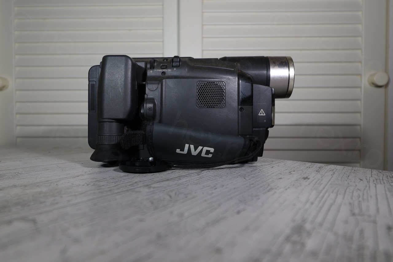
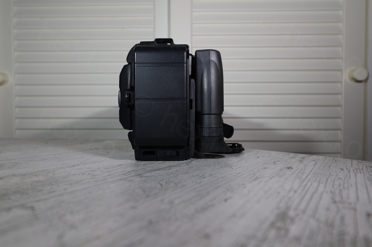
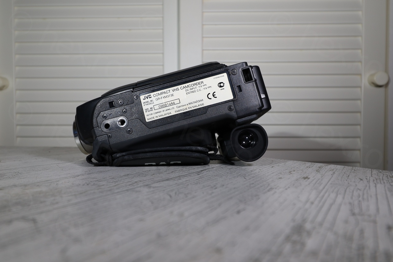
JVC GR-FXM373E


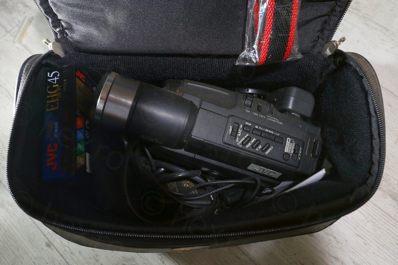
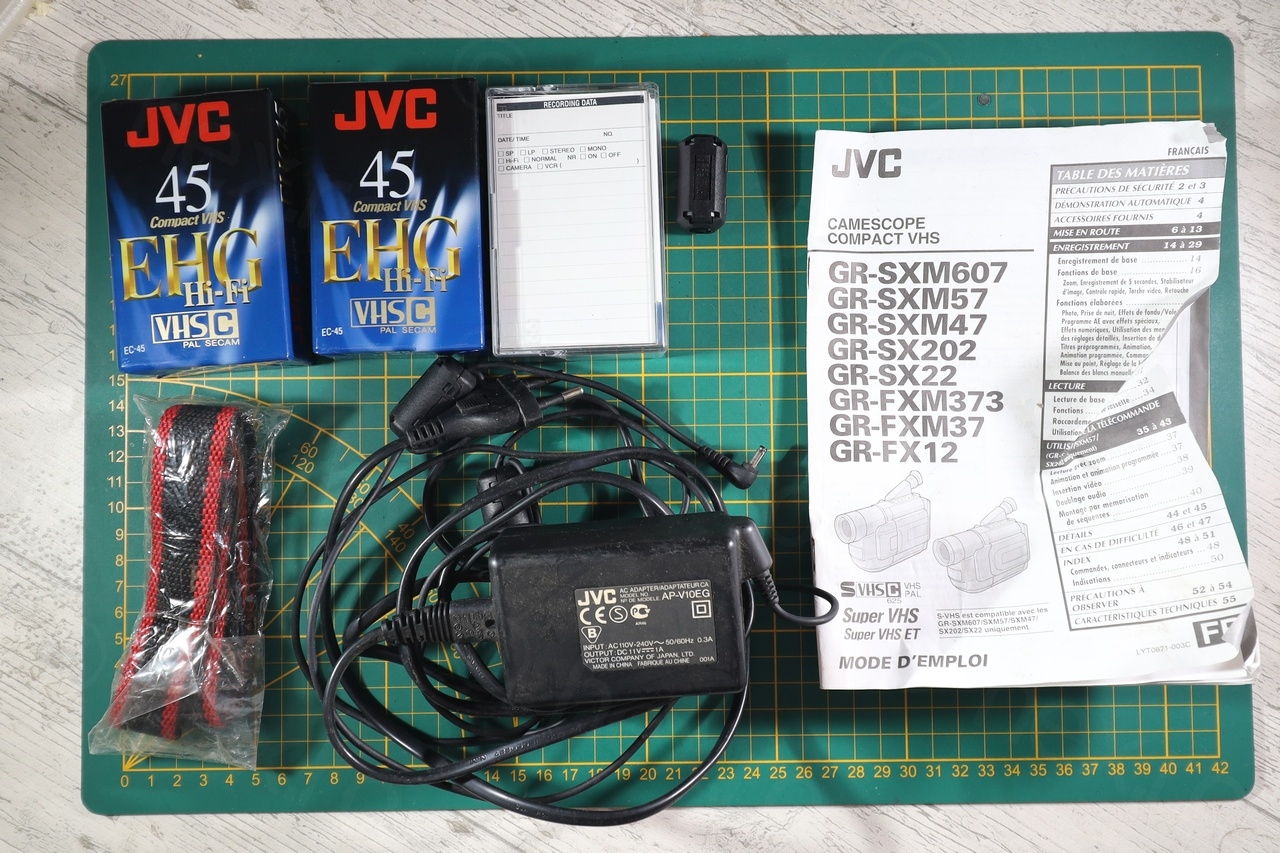
The bag also contained two new tapes, an empty box for another tape, the charger and a battery. But first a little overview of the camera:


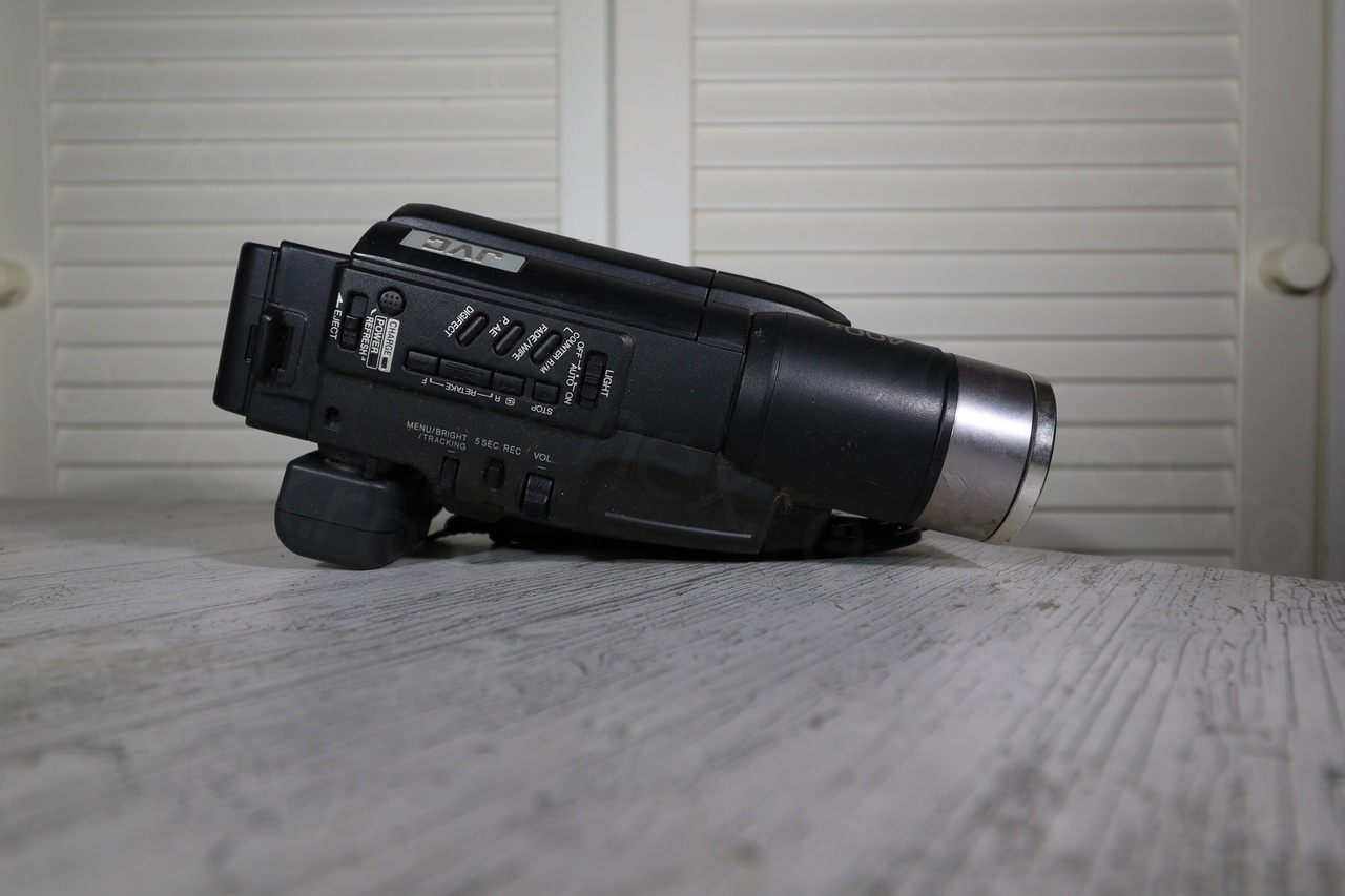
Surprisingly, the camera still worked. I never try to charge old batteries, but since the power adapter was included, I plugged it in. The camera has a flip out LCD screen which acts like a view finder – and when the LCD is out, the monochrome CRT viewfinder shuts off. There was also a tape inside containing family memories.
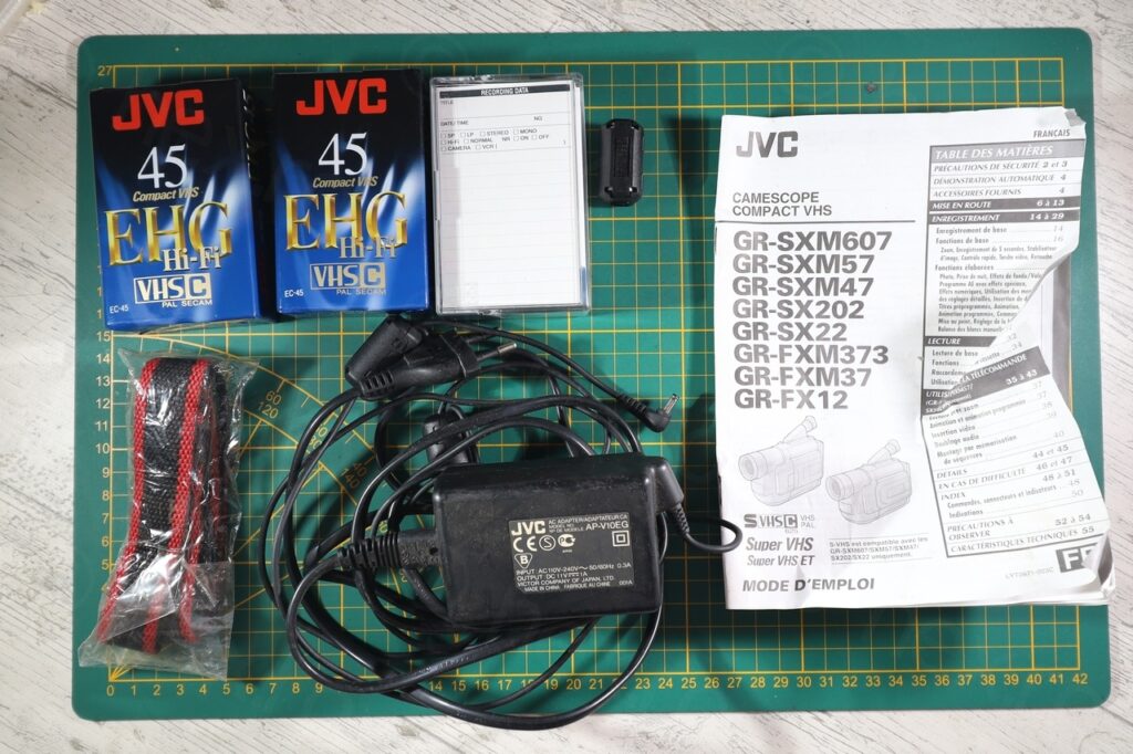
Contents of camera bag 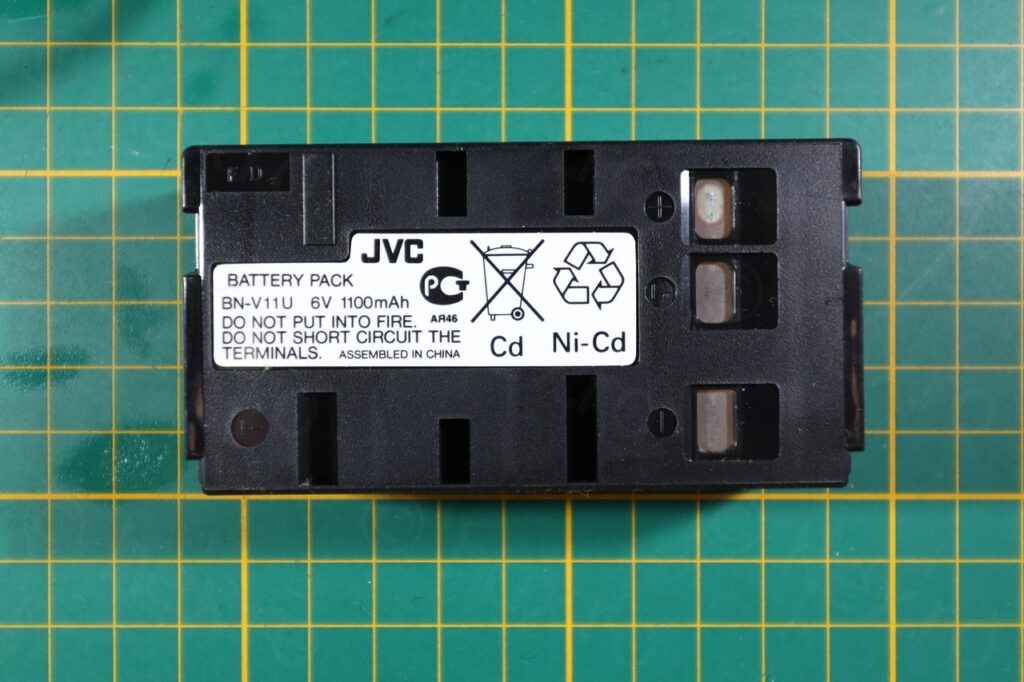
JVC BN-V11U 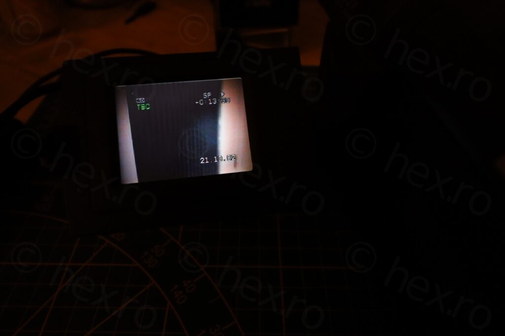
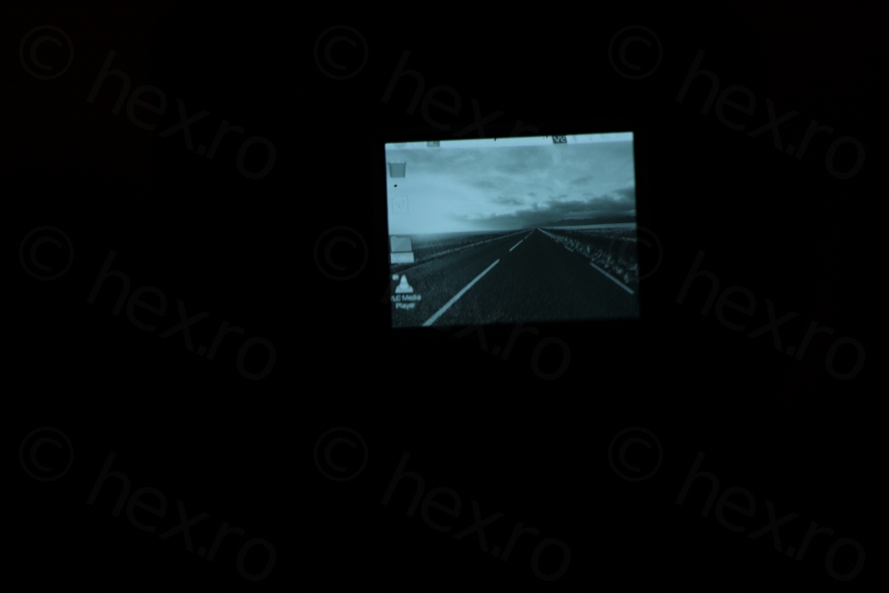
Capture from LCD 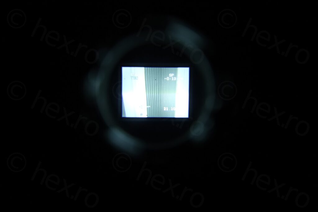
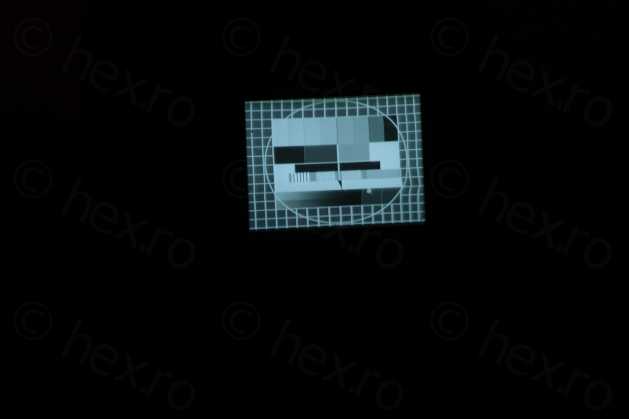
Capture from CRT View Finder 
Tape ejected


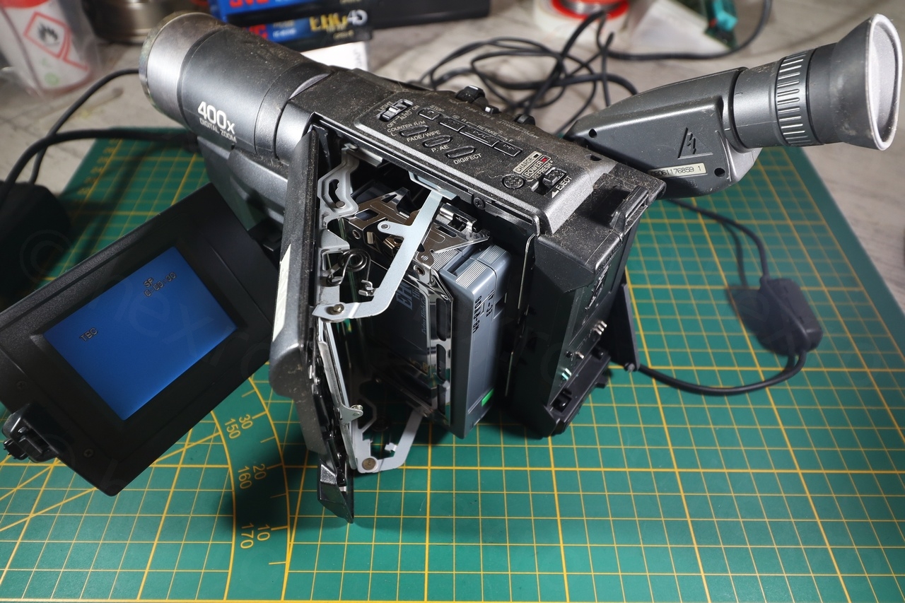
The camera was very easy to dismantle to get to the EVF unit. Having a 5 wire connection cable, this looked good and easy enough to try to power the CRT independently of the camera:
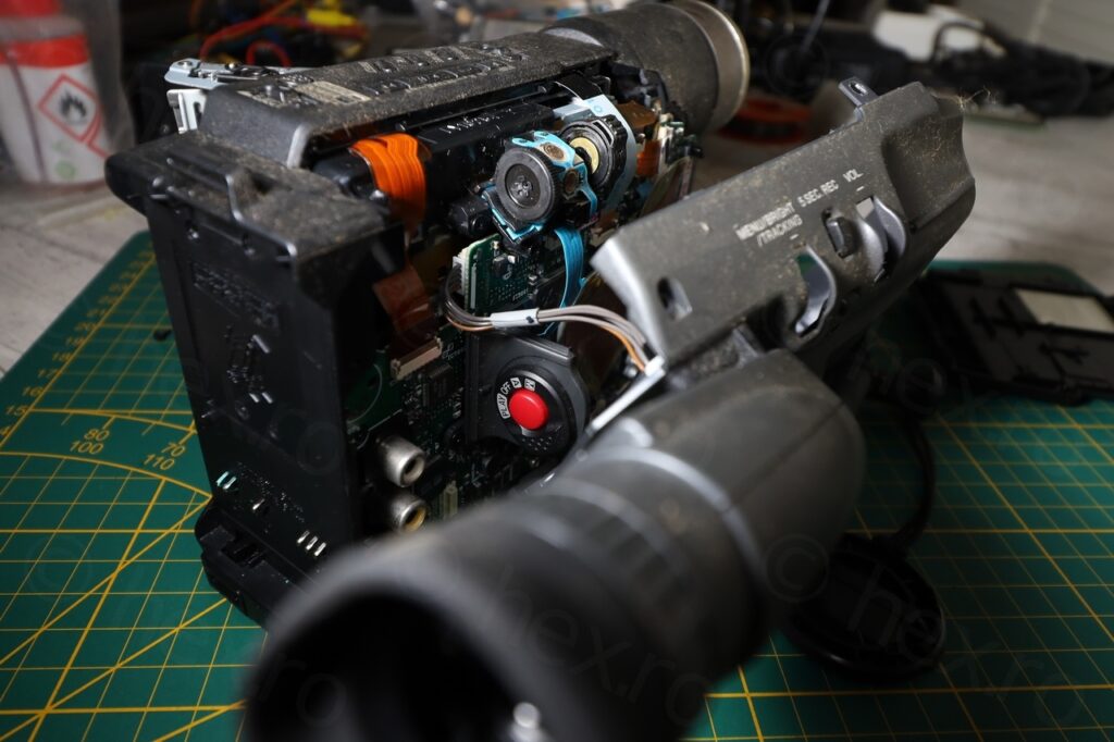
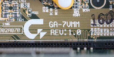
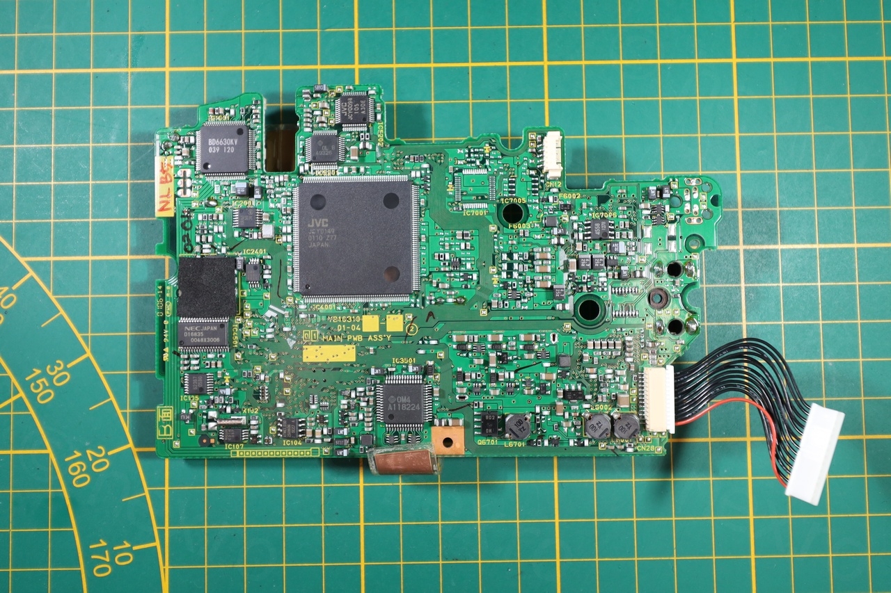
Camera seems to be a new camera (compared to others that I have took apart), made in March 2001. The insides were very clean, almost a single board camcorder.

Date Code 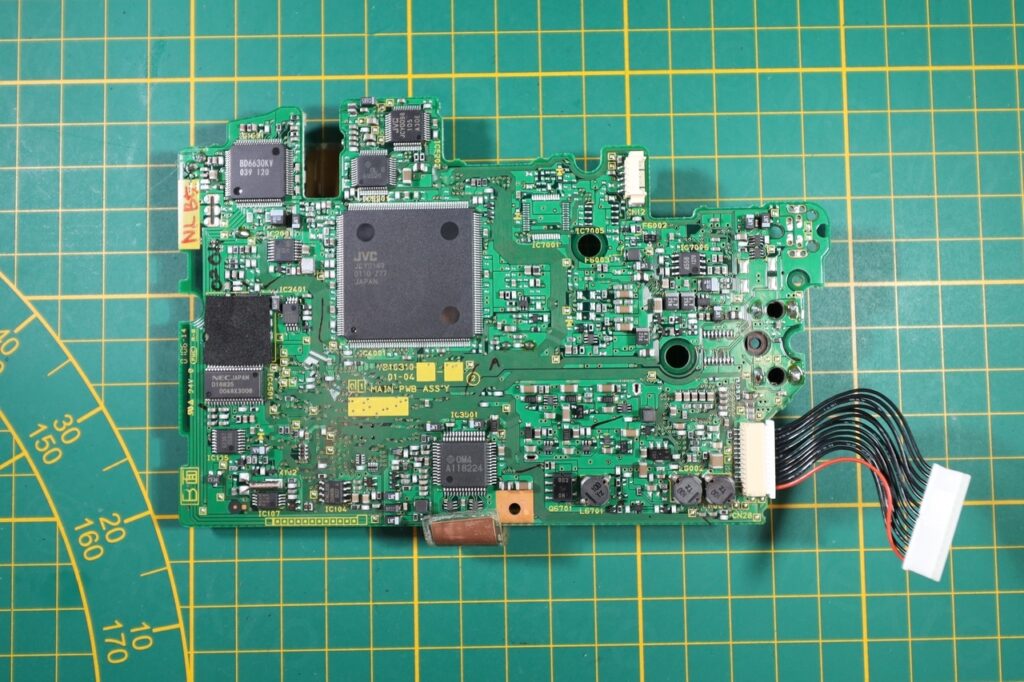
Motherboard
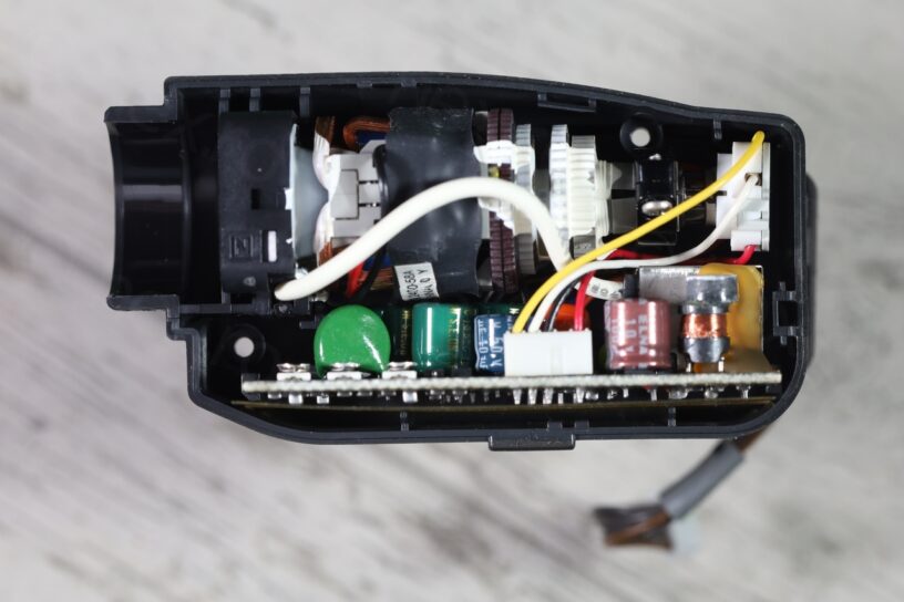
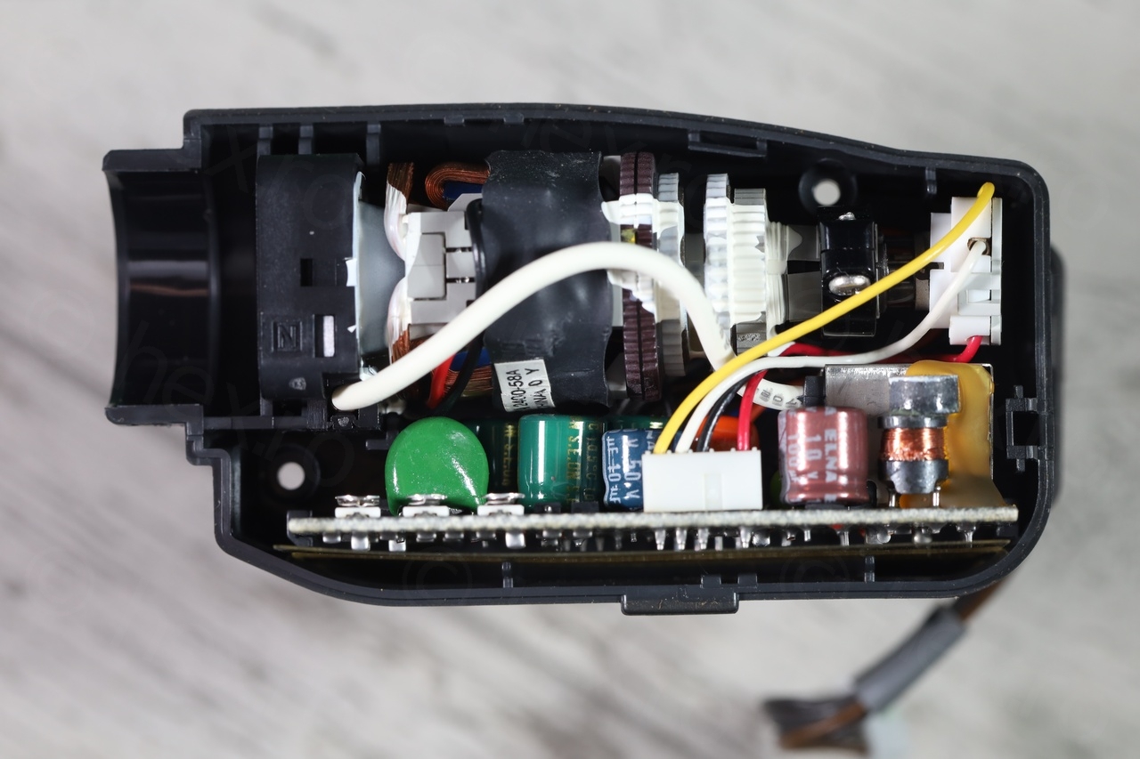
Electronic View Finder
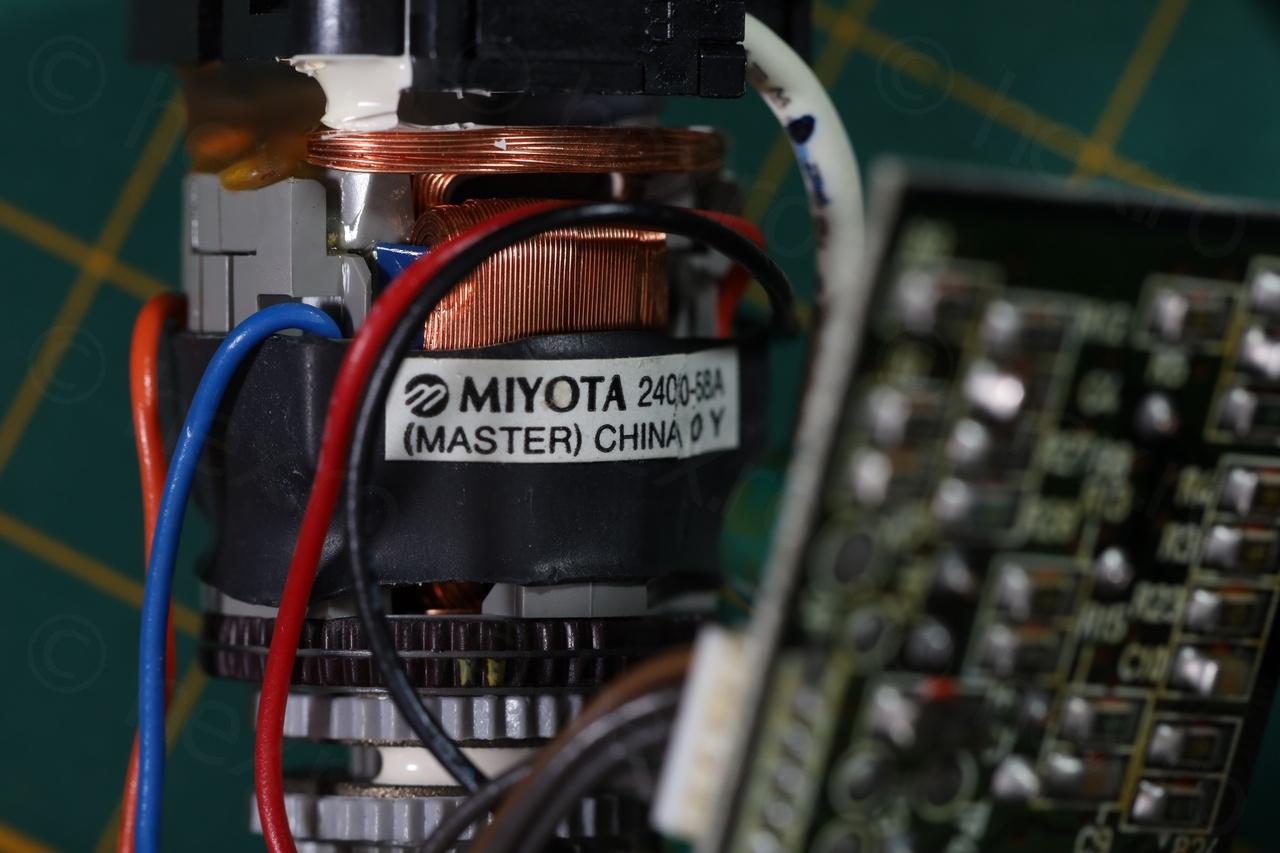
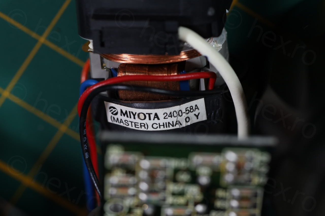
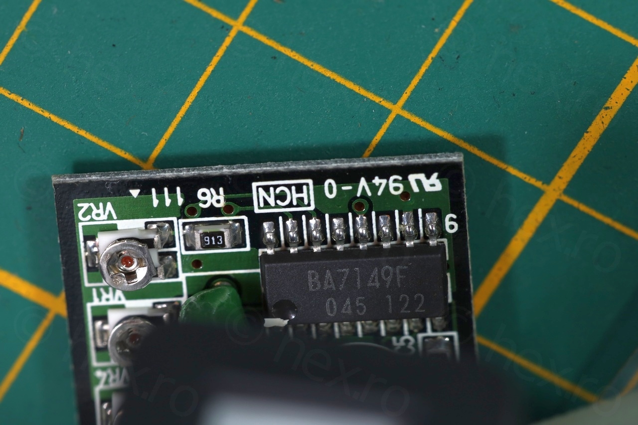
The EVF unit has no external markings except a serial number, but the model or voltages are missing. Inside I found a Miyota 2400-58a CRT driven by BA7149F driver IC:

EVF Unit 
Miyota 2400-58A 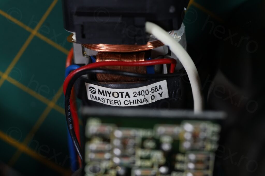
Miyota 2400-58A 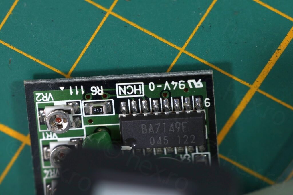
BA7149F 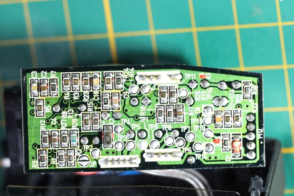
EVF board

Identifying the signal pins was a little more tedious than usual – there was a small frustrating catch. There are 5 wires, so this should be easy I figured. GND was connected to the Fly Back Transformer case, and 3 other pins of the FBT had continuity to a different wire on the connector -> this is a dead giveaway that should be VCC.
I’ve tried probing the 3 remaining wires with a Video IN signal, but nothing would happen, so I was stuck. Is the board defective ? This was not the first board that would not turn on when given VCC and GND, some very old cameras had an ‘Enable’ signal, active low, which would activate the EVF unit. And then I remembered that when opening up the LCD viewfinder, the CRT view finder would turn off (I assume to save battery). So what if one of the wires also was an Enable signal ? I went for the active low, trying to connect GND to one of the remaining 3 wires and success! The CRT turned on 🙂

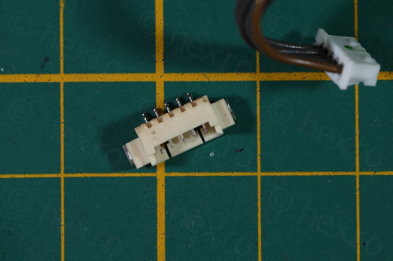
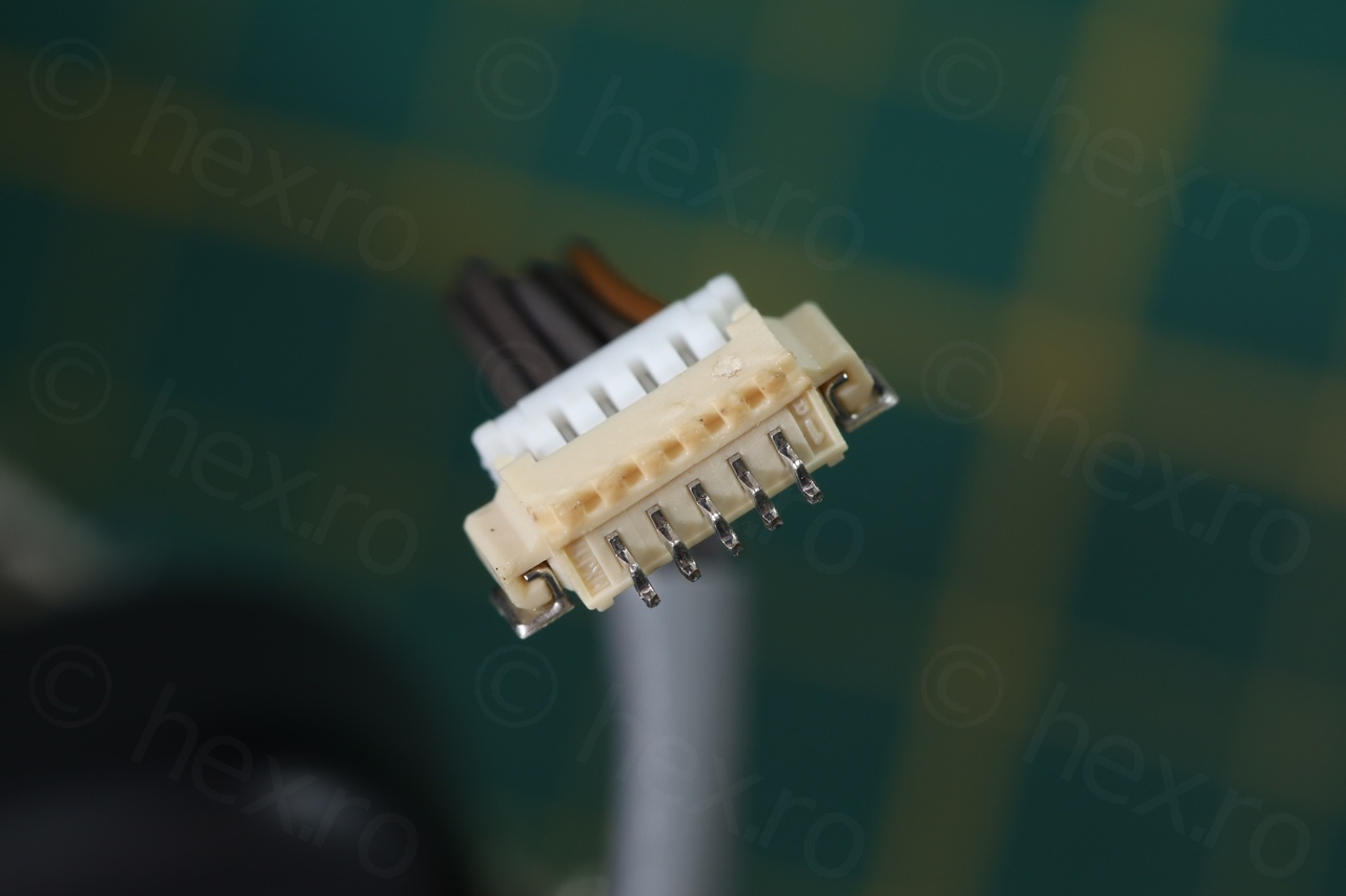
Connector desoldered 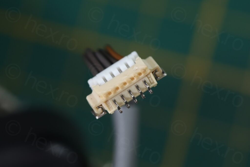
Connector plugged onto EVF cable 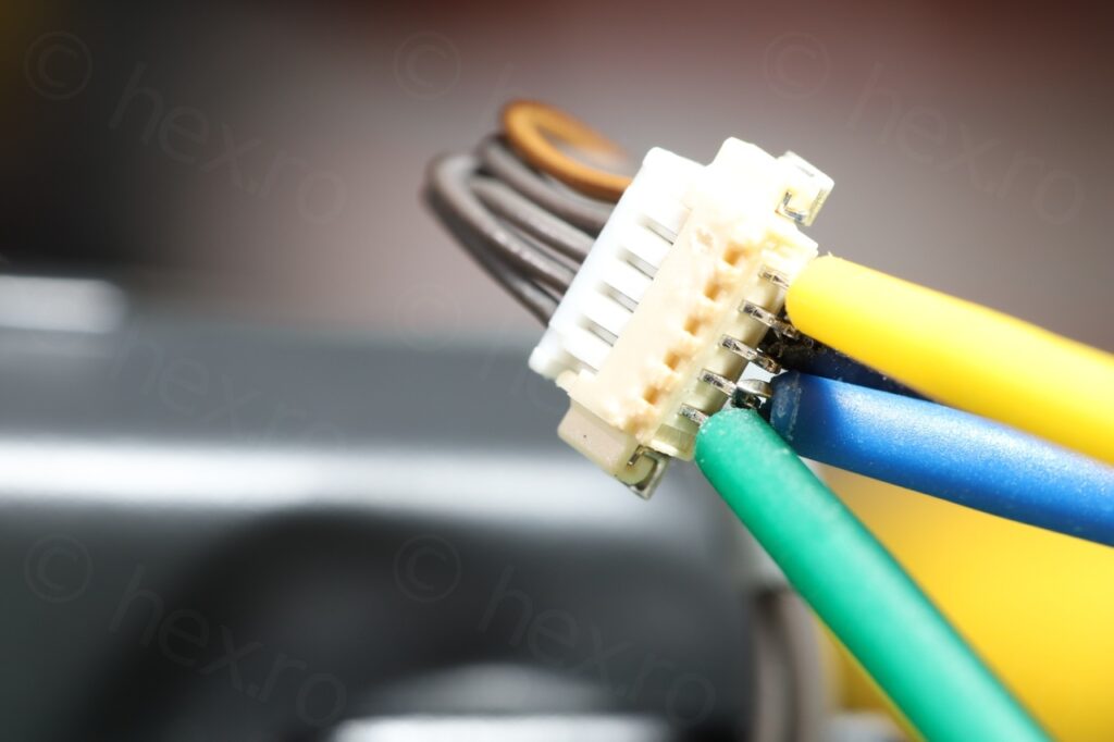
Green = VCC, Blue = GND, Black = GND, Yellow = Video IN

I have not identified the middle pin (out of the 5 of the connector), so the active low, Enable signal, is on the second pin from the right.
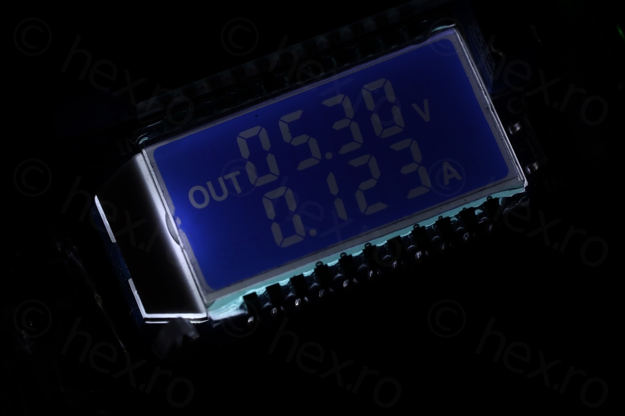
The EVF needs 5.3V and draws about 120mA. This is a little more than what I expected as consumption is around 80mA on other driver boards. It may be that the Enable pin needs a resistor ? Without a schematic (was not able to find one online) I have no idea.
There is also a weird effect, as the voltage lowers, there is a ‘white glow’ that starts smearing from the ligher colors towards the darker areas of the image. Other boards just become more blurry.
But the CRT works and I did not have to swap leaky electrolytic, so that is good 🙂
Leave a Reply