

Introduction
There seem to be two types of sellers at the flea markets, some that I call “mercenaries” and some normal ones. I call first ones mercenaries as they are very ruthless in going for the “kill” – it can only profit them. Even if I could buy a CRT camera from a normal seller at a normal price (let’s say, 5 – 10 Euros), mercenaries will ask 30+ (sometimes 80). They have nothing to loose.
However, negotiating with them at the end of the day may help – it is not true they have nothing to lose, they had a reason to come, to setup, so I guess going back home empty handed is not so great ? At the end of the day they are willing to listen to arguments and sometimes they do drop the price to the normal one. Otherwise, I’m not buying – not looking to reinforce a predatory behavior.
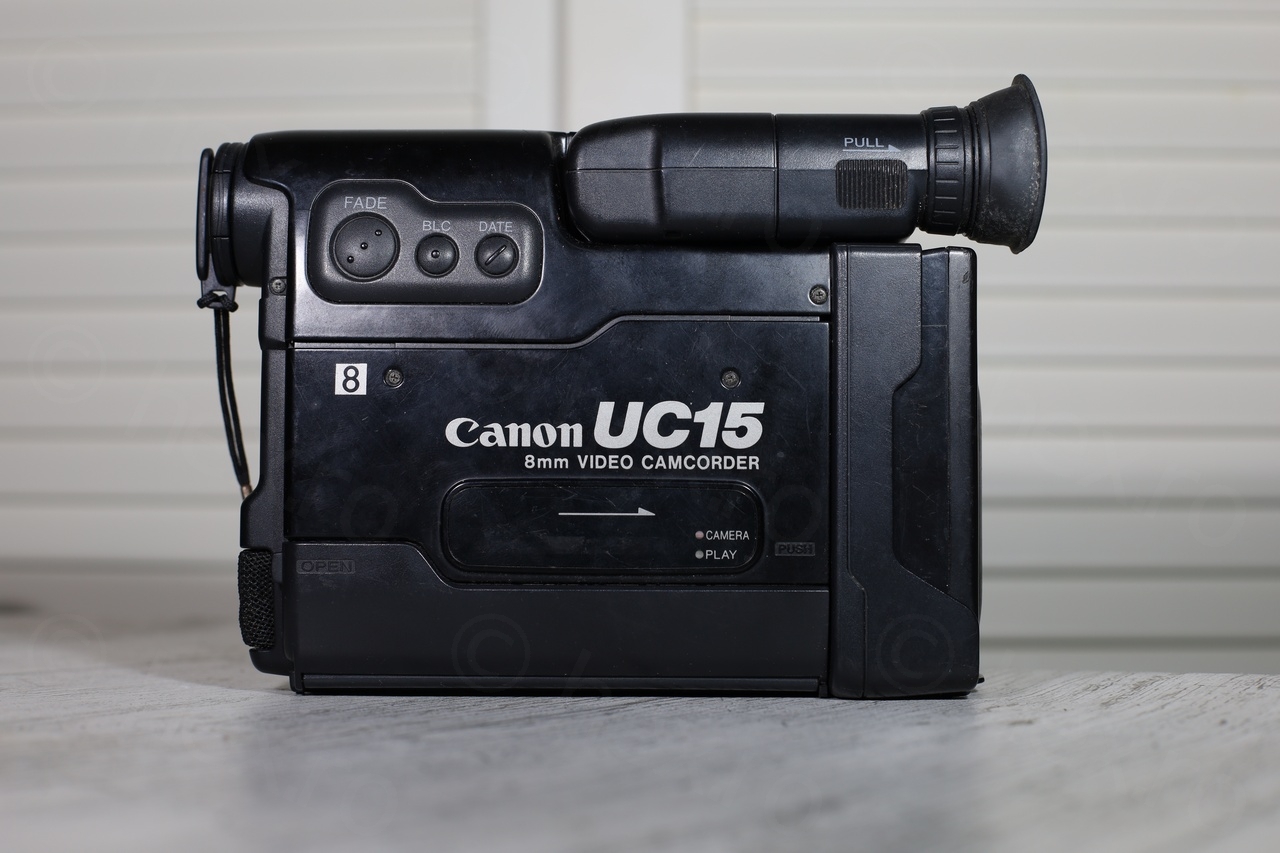
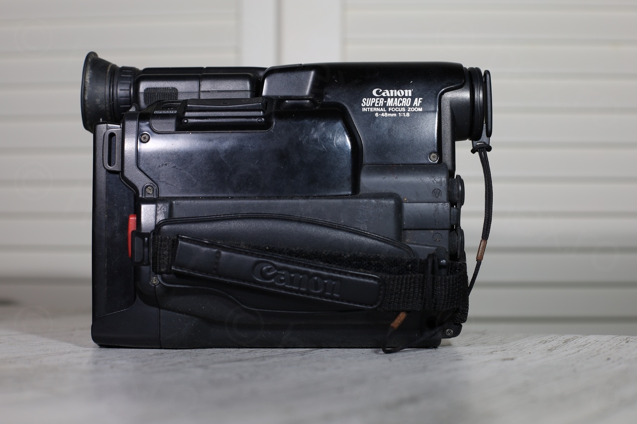
I bought the Canon UC15E camera from a mercenary seller at the end of the day 🙂 but I am not always lucky.
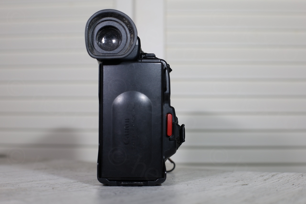


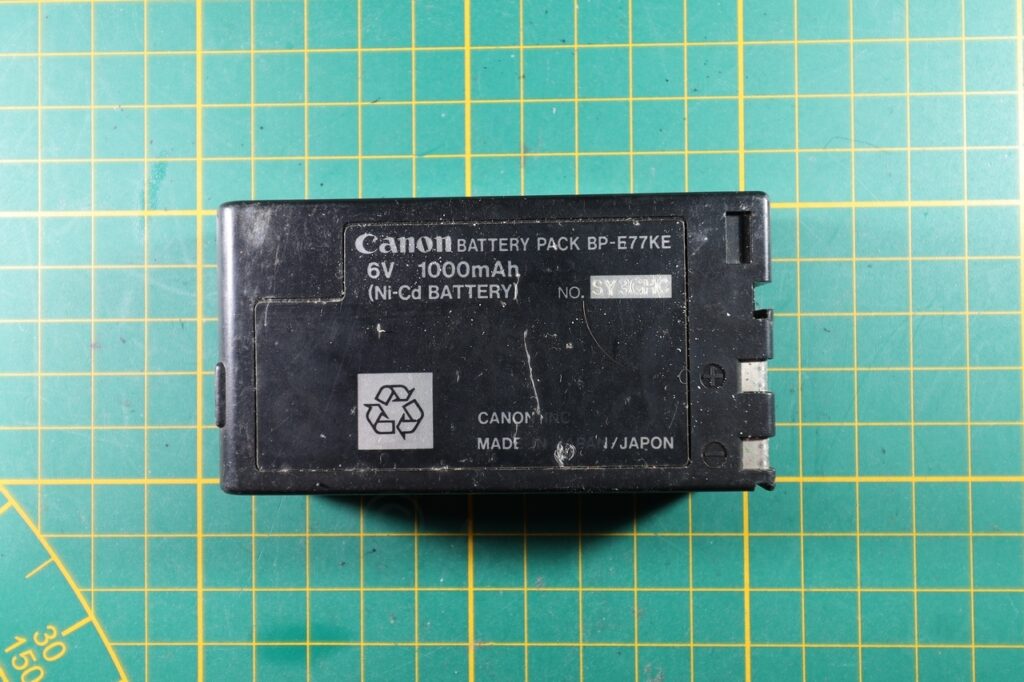
It also came with a battery – of course I’m not going to touch it – but it is good to see what the camera expects from the battery.
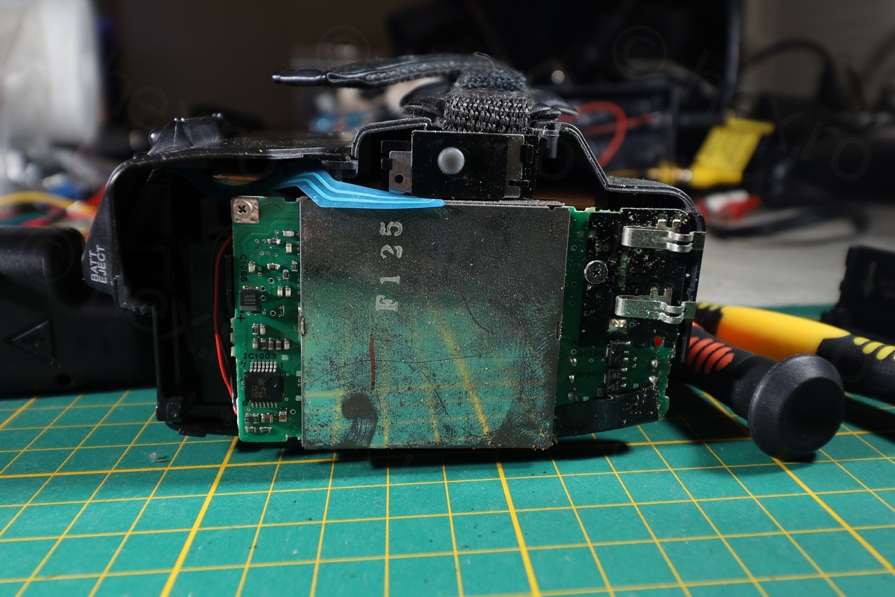
I tried to power on the camera with an external power supply but there was absolutely no sign of life. Even the current meter was showing no current was going through. I was worrying that all capacitors were leaky, maybe even the ones in the Electronic View Finder ?
One of the reasons I was curious about the camera was that the mini CRT seemed really mini. Visually it was tiny compared to others from similar cameras. I was curious to get to it ASAP.

Rusty fingerprints! 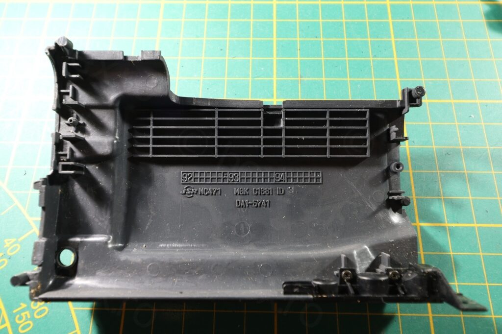
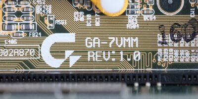
Date code: May/June 1992

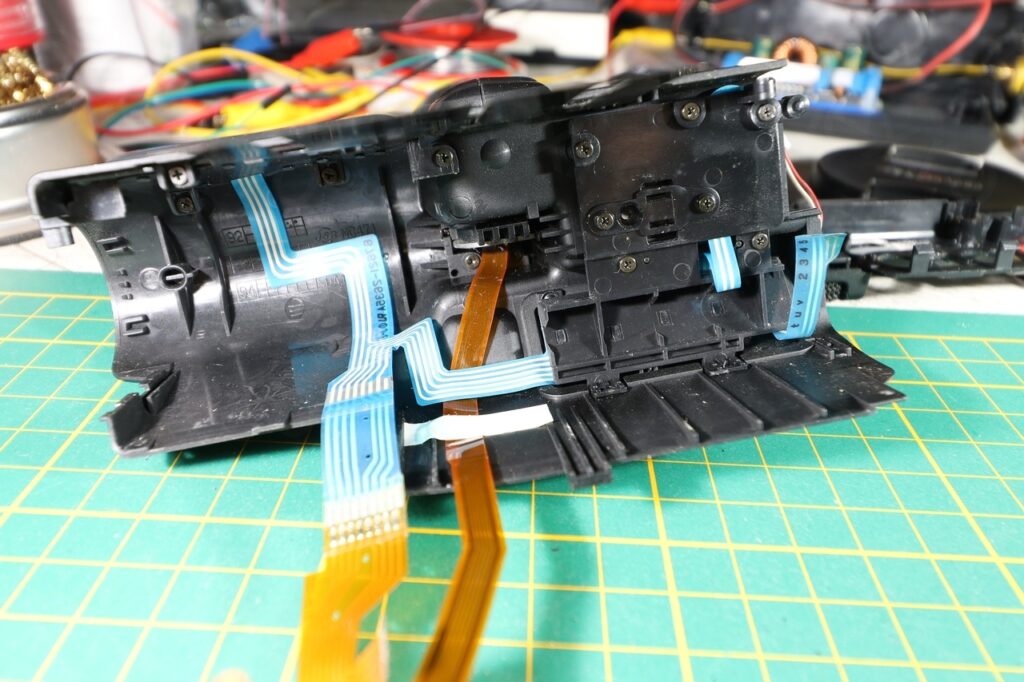
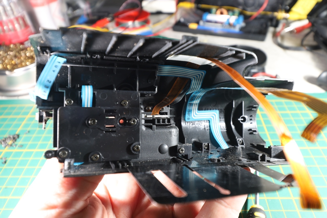
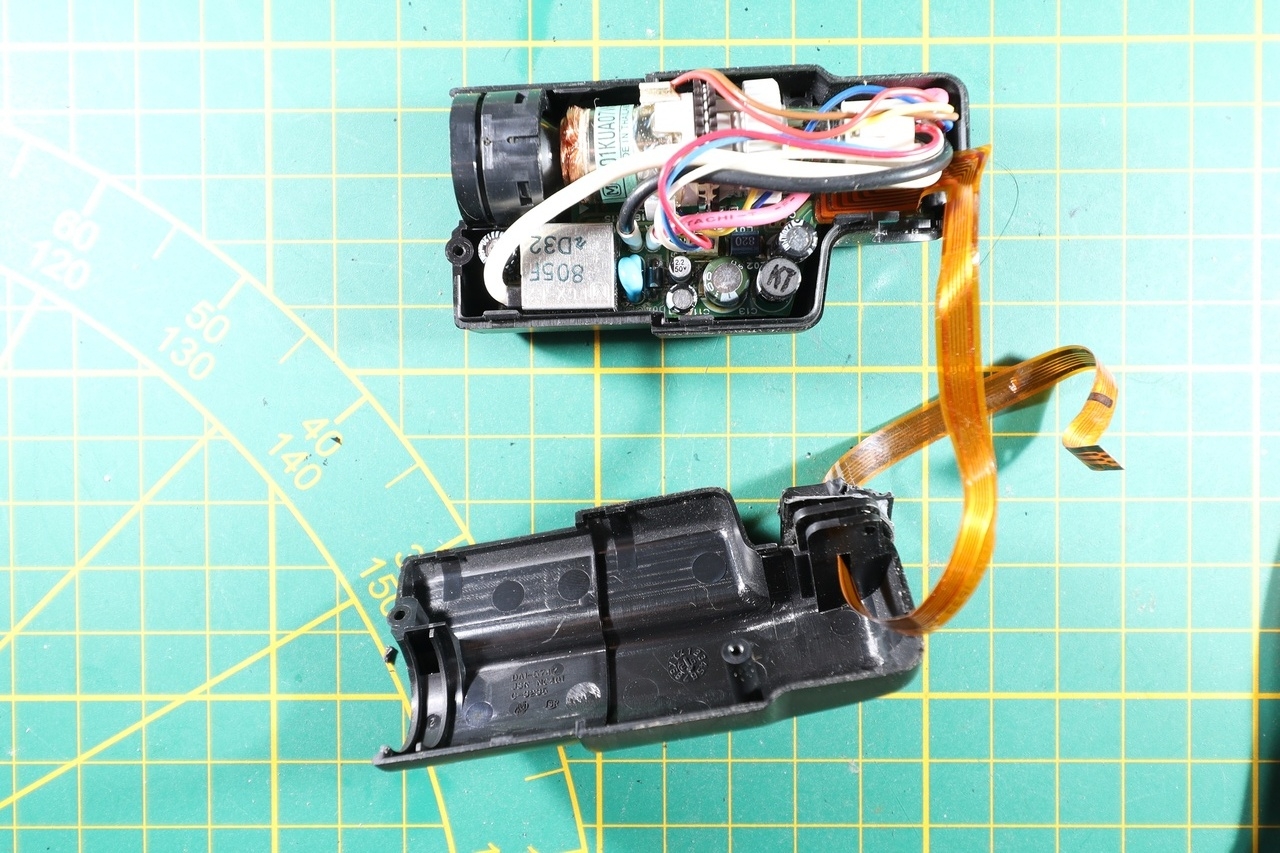
Getting the EVF unit detached from the camera was a real puzzle. I had to crack the plastic to be able to detach it, and I believe there were some retaining metallic balls that were locking into place. I did not spot them before (or maybe I didn’t pay enough attention), but one thing that I did pay attention to was not to break the connecting flat cable:

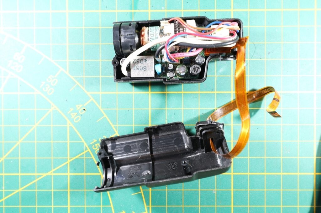
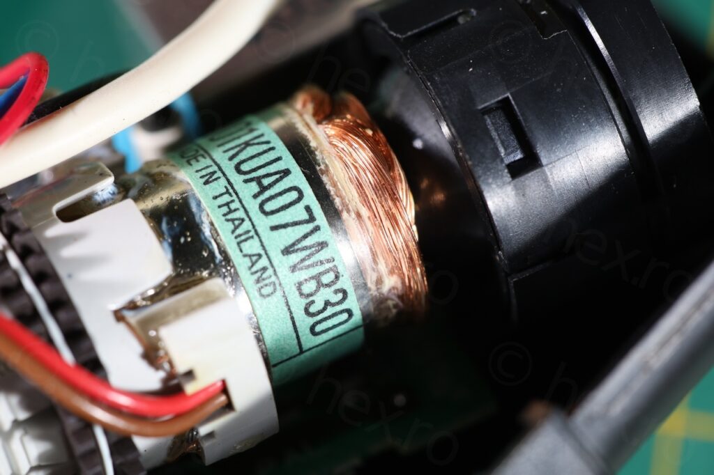
The thing IS tiny!

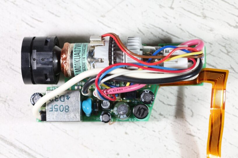
I would prefer not to have to open the EVF unit to test it, but unfortunately it is the only way I can identify the signal pins. And surprise surprise, this is the first driver board that seems to have a bodge – a wire connects the EVF IC back to a capacitor on the top side of the board:
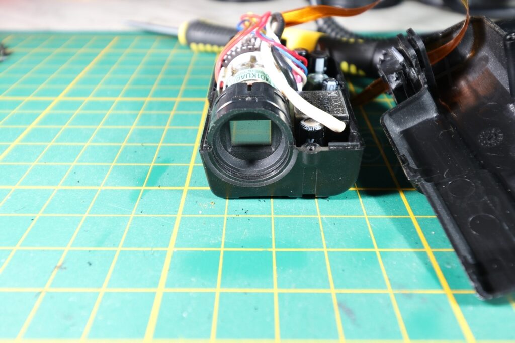
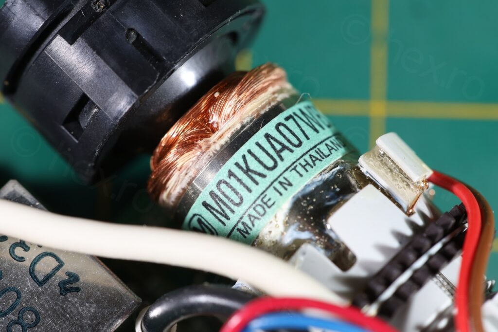
Width seems smaller than 10mm 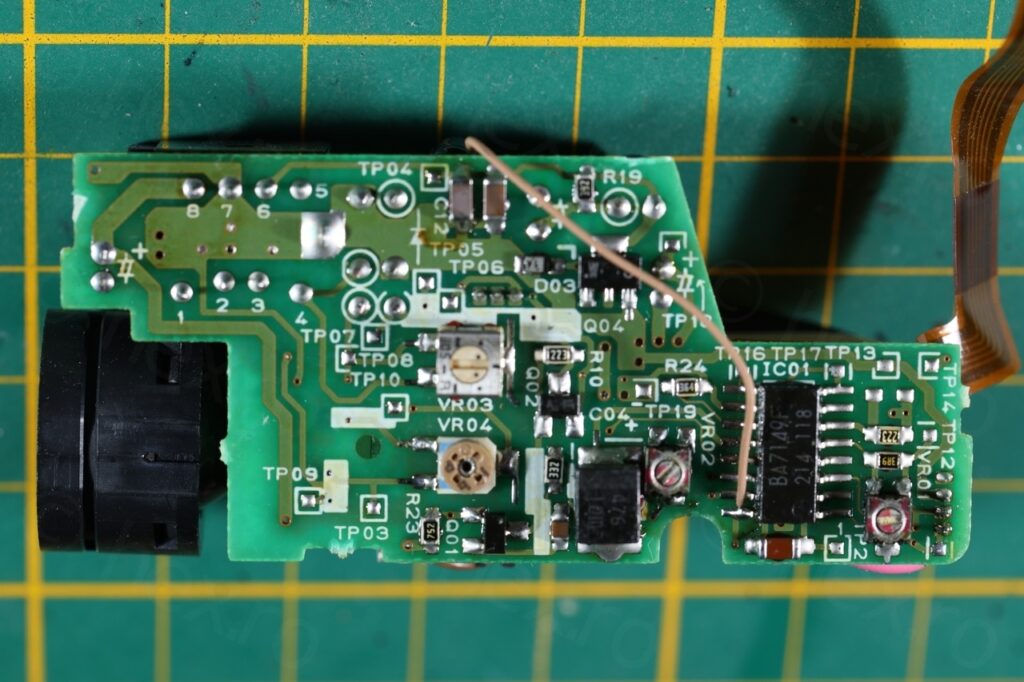
Back of the driver board 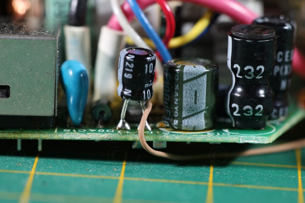
Bodge wire 
BA7149F EVF driver

Identifying the signal pins is easy with these boards. GND is always connected to the FBT case, and some of the pins of the FBT are connected to VCC. So this way I could identify the VCC and GND. Once powered up, identifying the Video IN can be done through trial and error on the other pins.
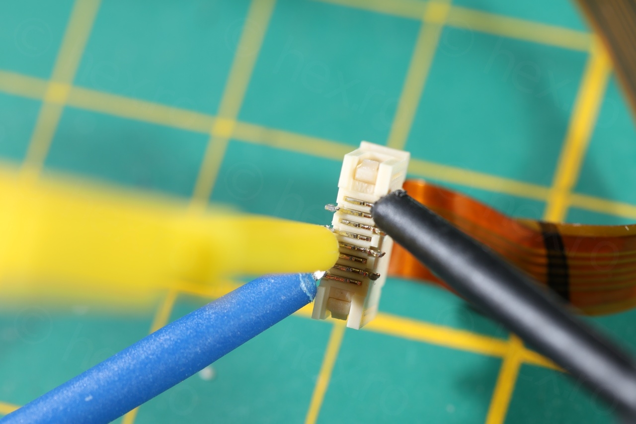
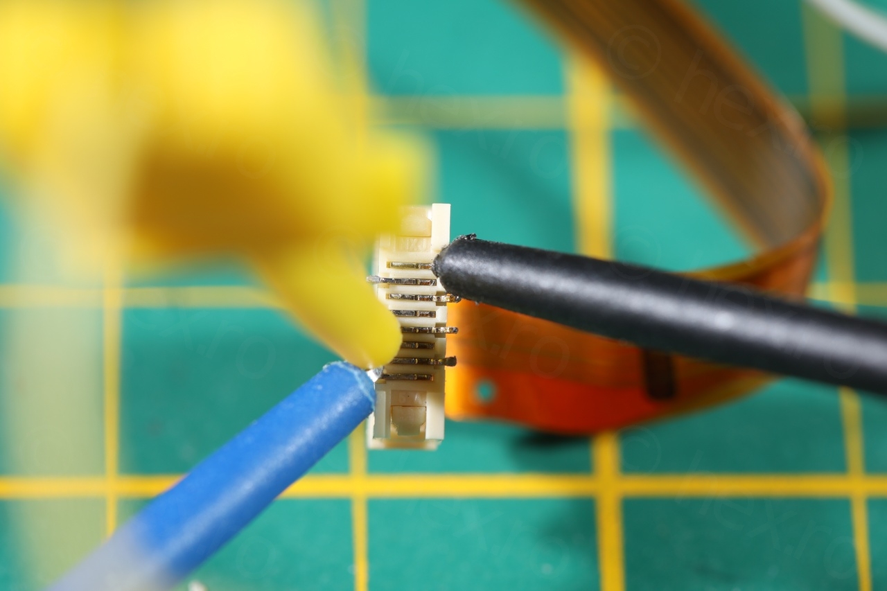
I have also decided to salvage the connector where the EVF flat cable was attached to. It makes it way easier to connect the mini clamps – instead of fiddling with the flat cable.
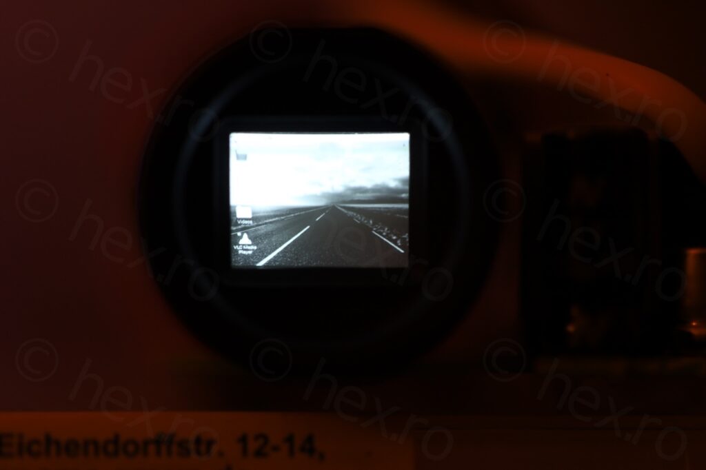
Raspberry PI desktop 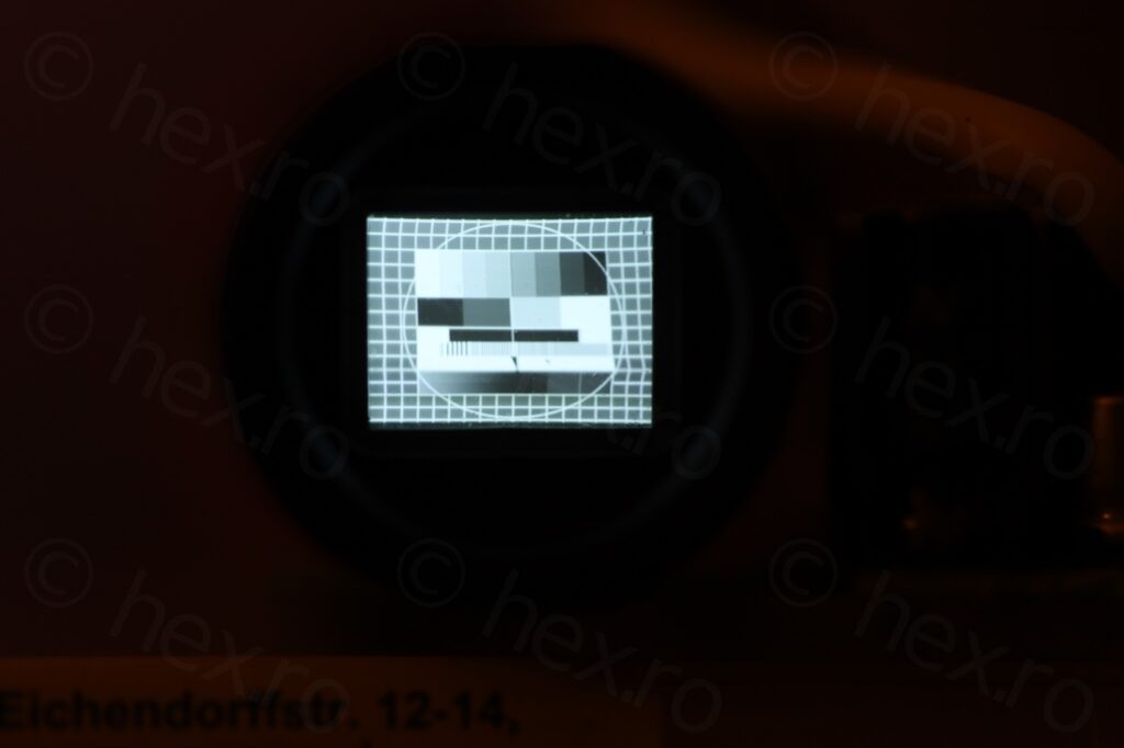
TV Pattern

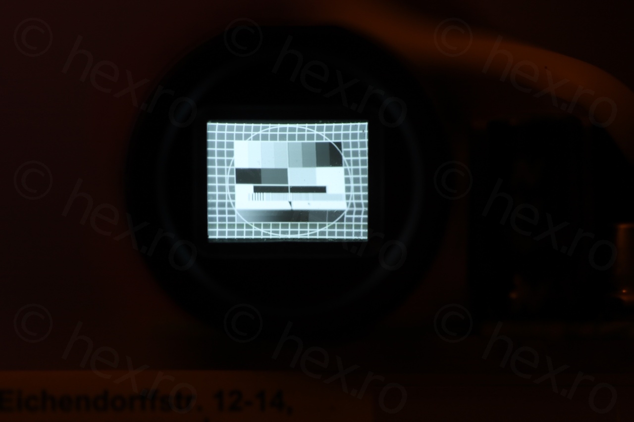
There seems to be some distortion of the image especially in the lower right corner. Not sure if recapping would fix this, but if it still works like this, I prefer not to touch. The board is really tiny too and there is a small electrolytic capacitor very close to the FBT. I would have to de-solder some other components just to get access to the tiny pads.
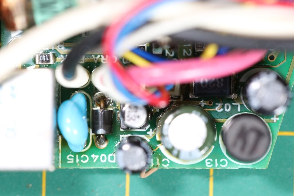
Very dense layout 
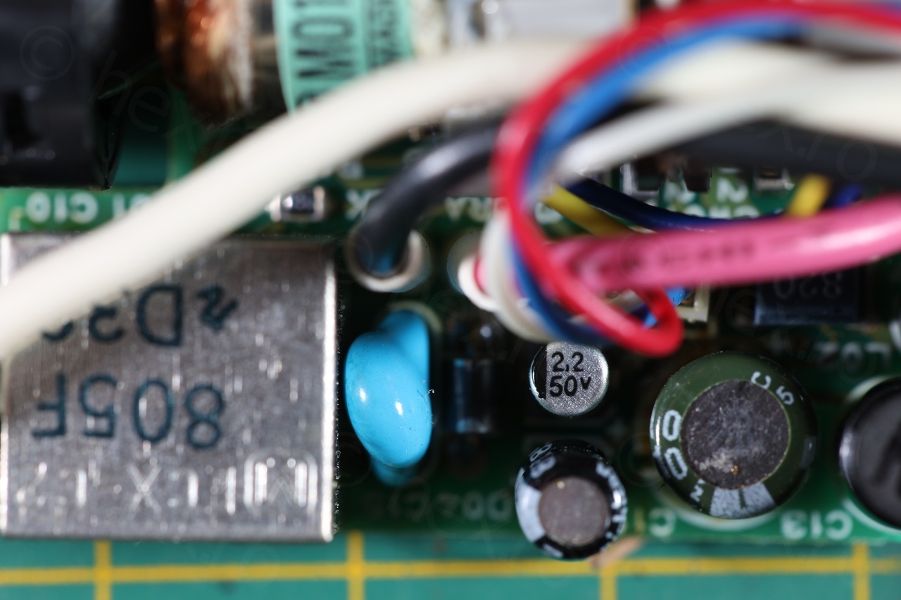
Capacitor on Top Right of FBT

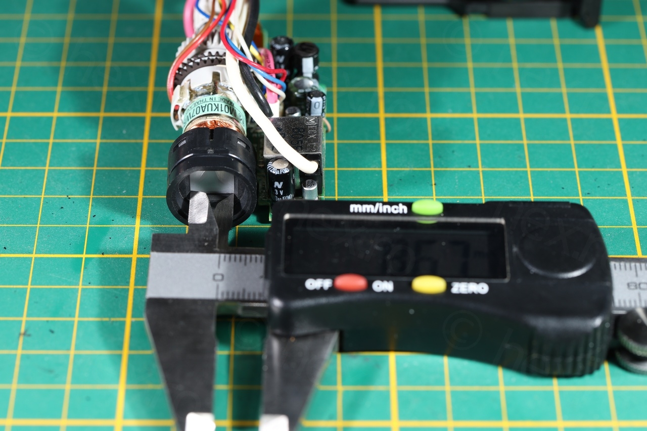
Out of curiosity, I have decided to measure the screen (the opening):

Width is approx. 8.67mm 
Height is approx: 6.49mm
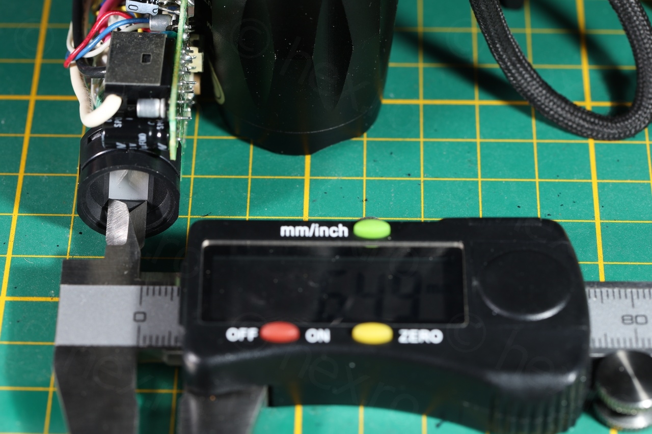
This makes the CRT having a usable diagonal of 10.8mm.
I have found a Japanese blog – where kamomesan (hope I got the name right) used the same CRT to create a DIY audio frequency indicator. Very cool idea for a future project, although I think I am lucky having a working driver board. This way I can use directly RPi to generate the audio waveform instead of having to wind the transformer myself.
Tehan
hi! I am pretty sure the actual diagonal length crt is much larger when the plastic mask infront of the crt is removed. so why would they intentionally reduce the viewing area of the crt (they could’ve made the square mask larger right)?
Tehan
how much did you pay for it though?