


Found this mini CRT inside a Panasonic NV-A1F that I picked up at a flea market.
Camera
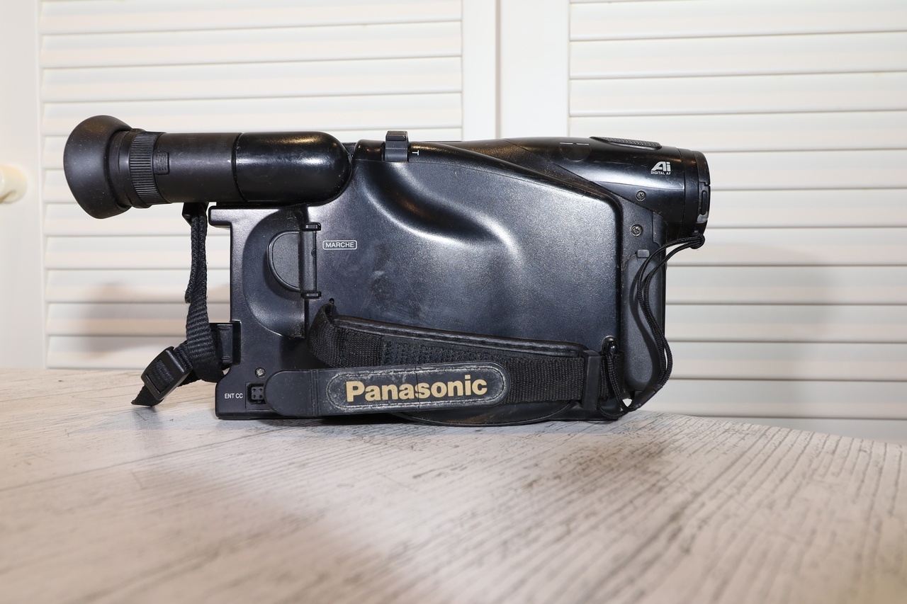
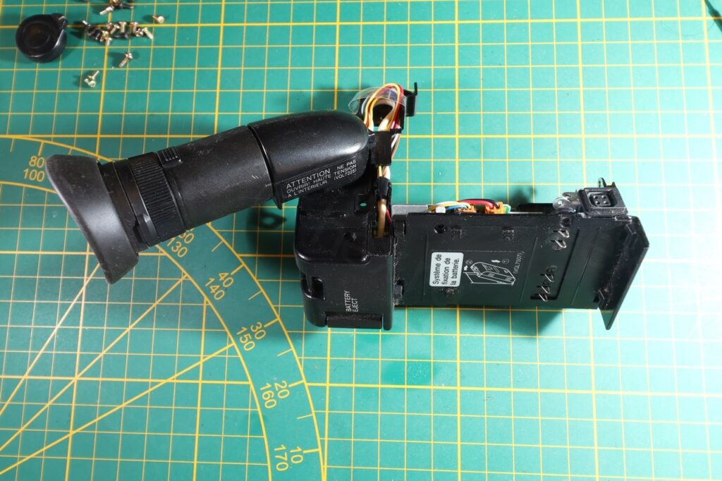
Camera looked nice and slim:
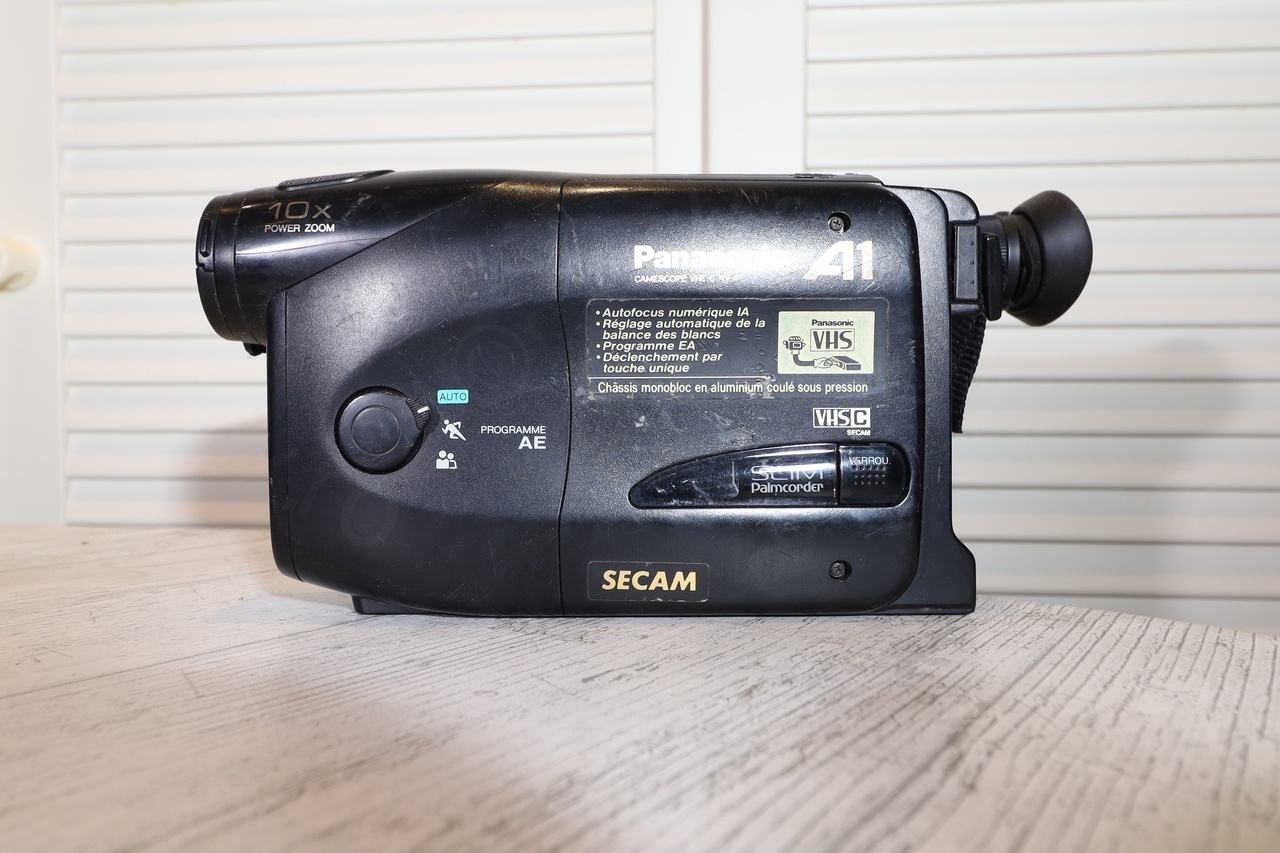
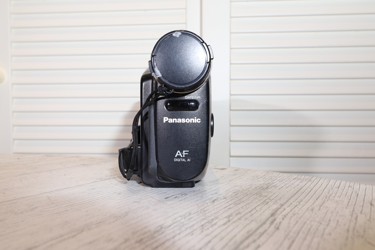
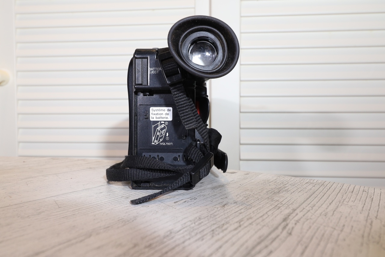

I’ve tried testing it. While initially it worked fine (for 2-3 minutes) just see that the view finder is good, the camera eventually stopped. Same voltage was provided externally, but now a RED led was blinking fast while only a clicking sound was heard from inside.
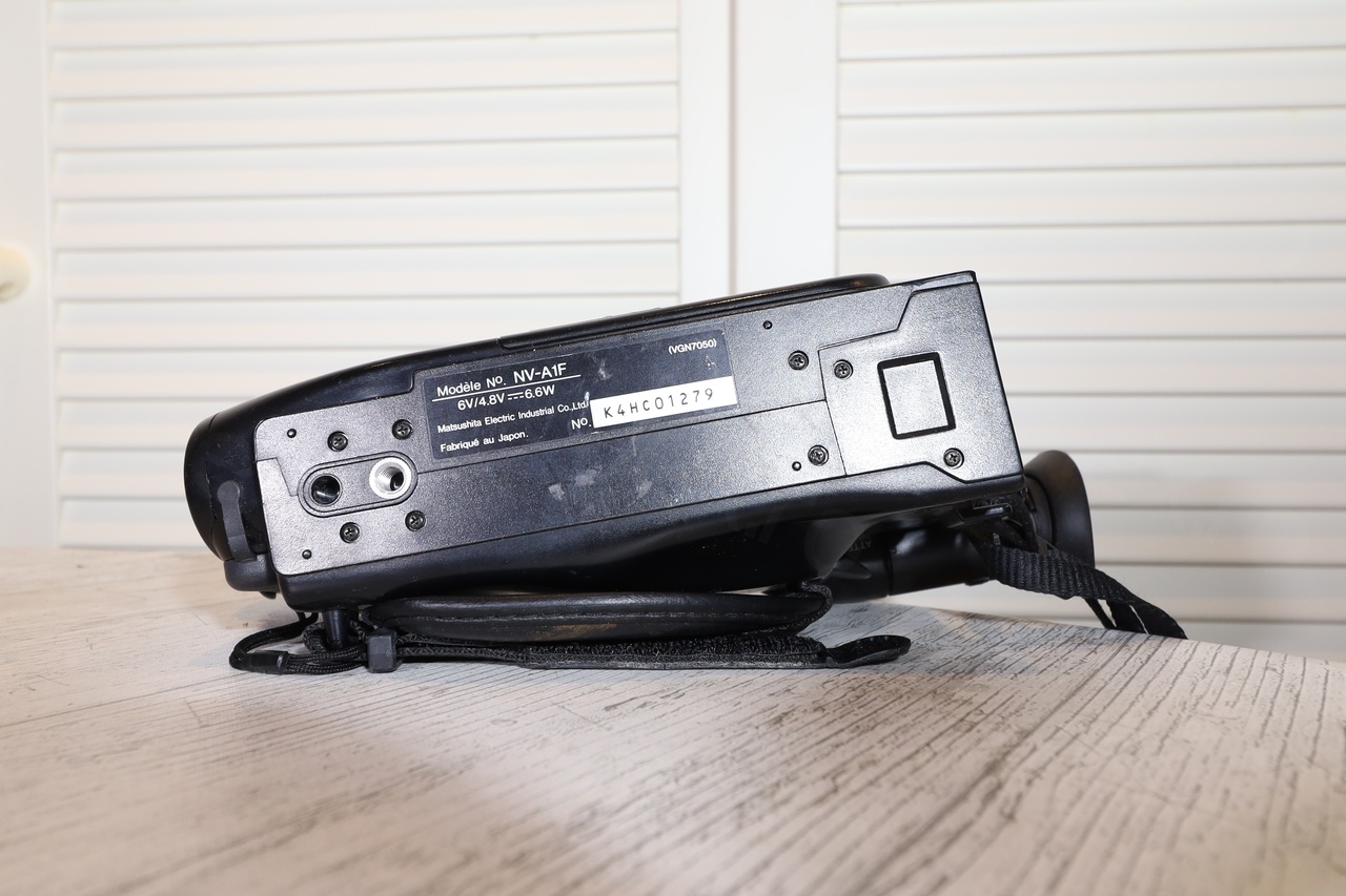
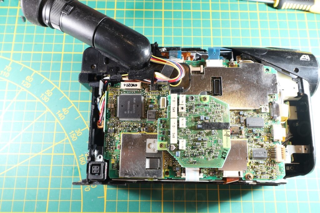
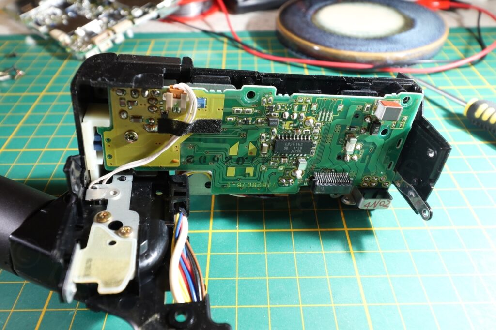
Taking apart the camera was very easy – and only an addon board had some bodges on the under side. Manufacturing date is Oct 1994:

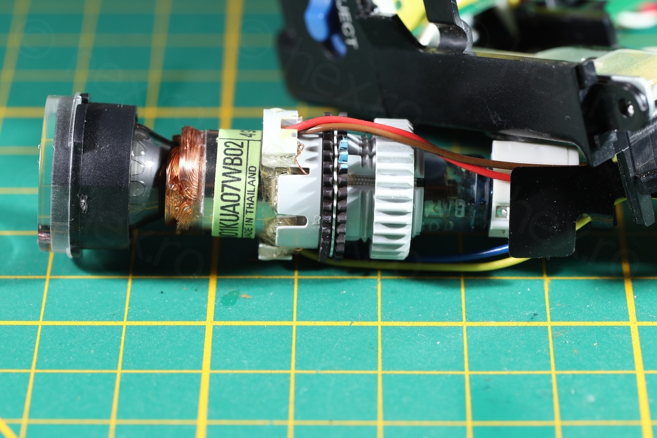
Electronic View Finder
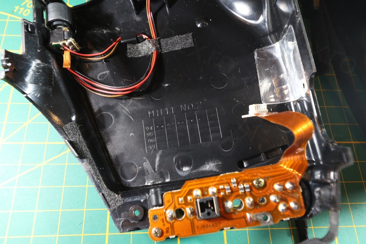
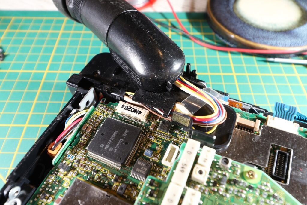
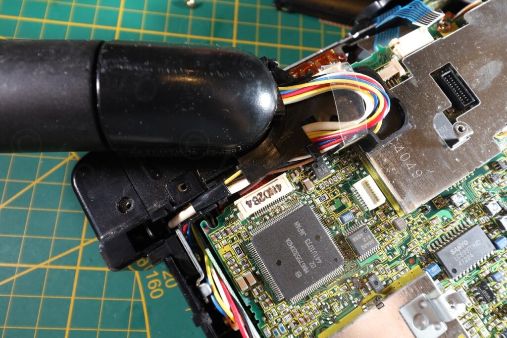
The EVF was tiny. I was expecting a very small board inside, similar to the recent Canon I took apart – but reality quickly set in. Instead of struggling to make a small EVF driver board, the EVF unit only housed the CRT! Long wires were routed to the driver board which was inside the camera!
Getting the CRT to run was challenging now, from few points of view:
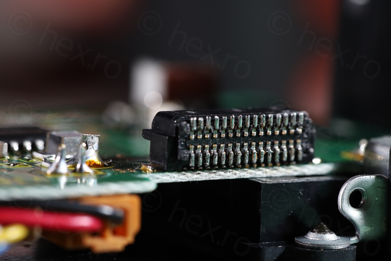
- During testing, camera CPU seemed to control the EVF unit (instead of it being permanently on). I needed to find the control pins.
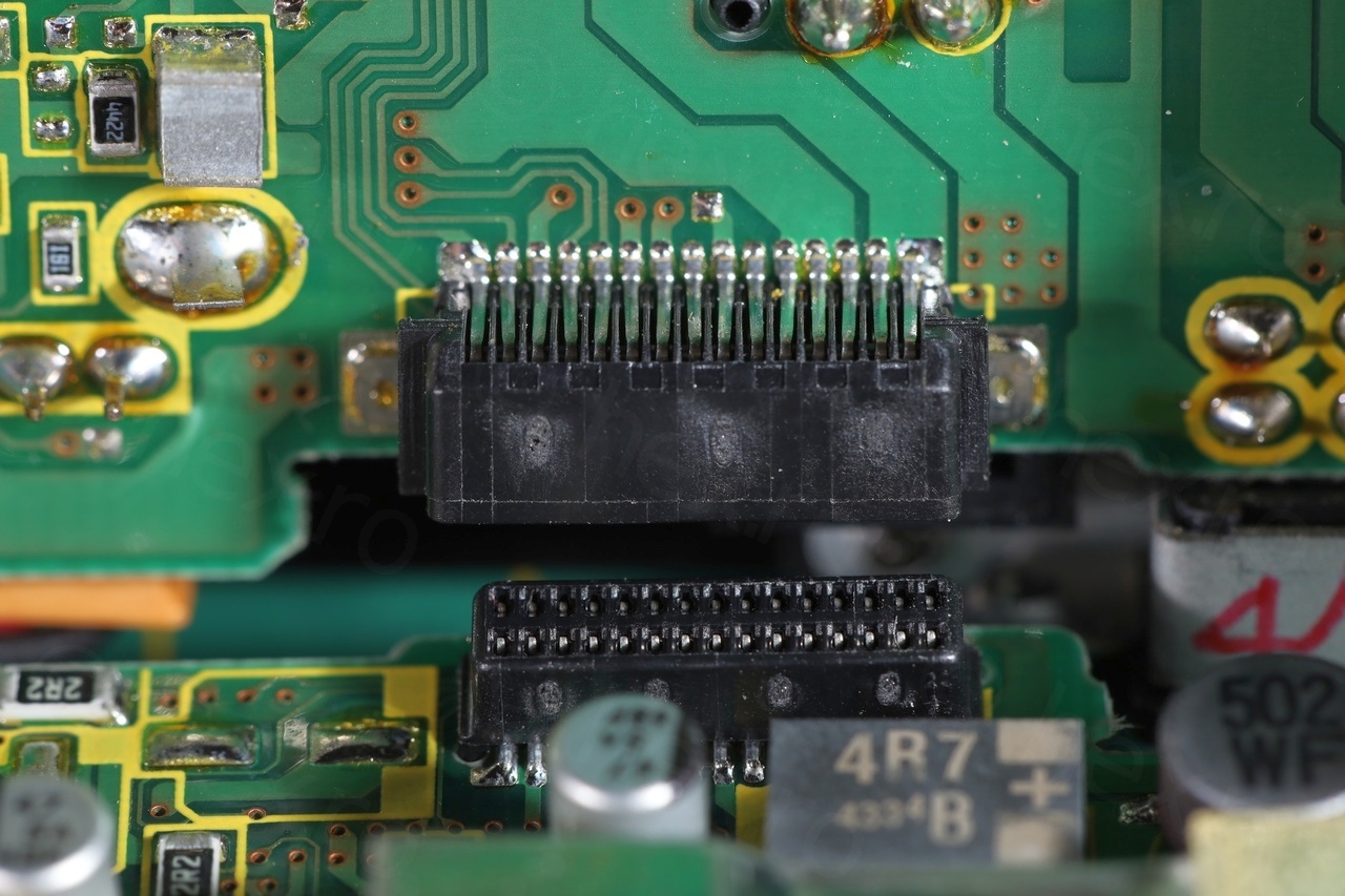
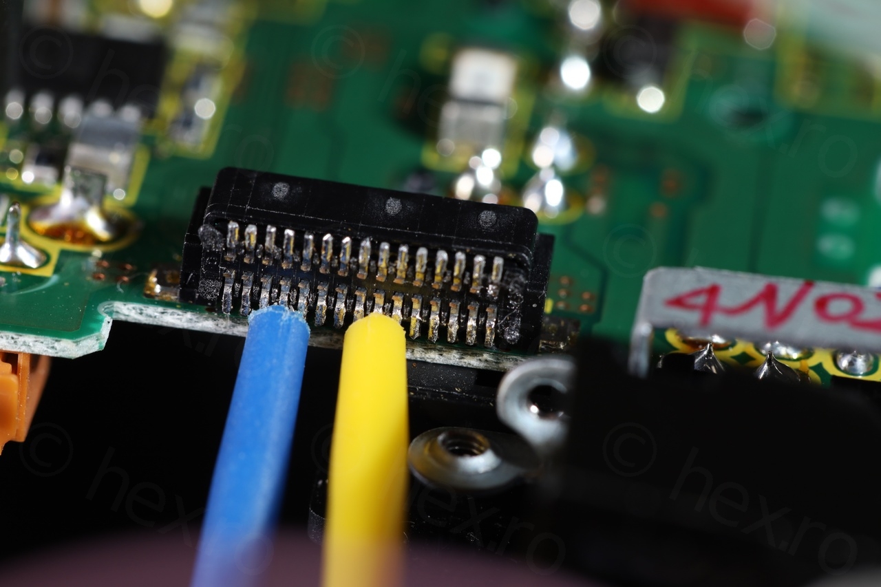
- But the motherboard connector had 30 pins.
Luckily, I was able to find the schematic of the camera online – and the 30 pin connector was there. While this simplified everything by a huge factor, I was not quite there yet:
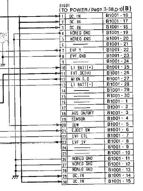
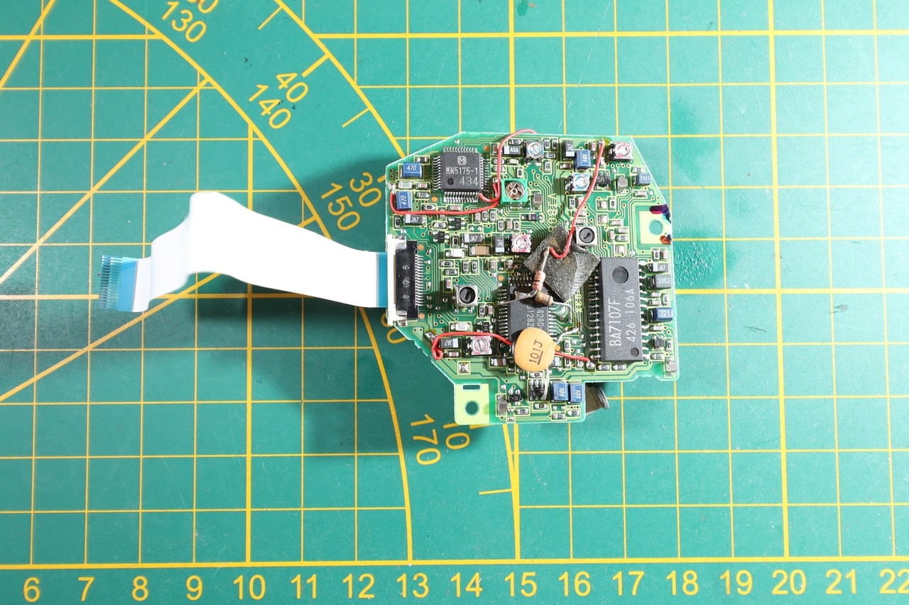
There are 4 pins having EVF: EVF Y (pin 7), EVF GND (pin 8), EVF CTL (pin 22), and EVF 5V. Provinding power was easy, at the 5V line was going directly to the IC / Fly Black Transformer. On some other circuit boards there can be an Enable pin that stops you from powering up the IC directly, as other parts of the board would still be un-powered. Here at least, I could try to power in the IC directly and it would work without me having to try to hook up to the 30 pin mother board connector.
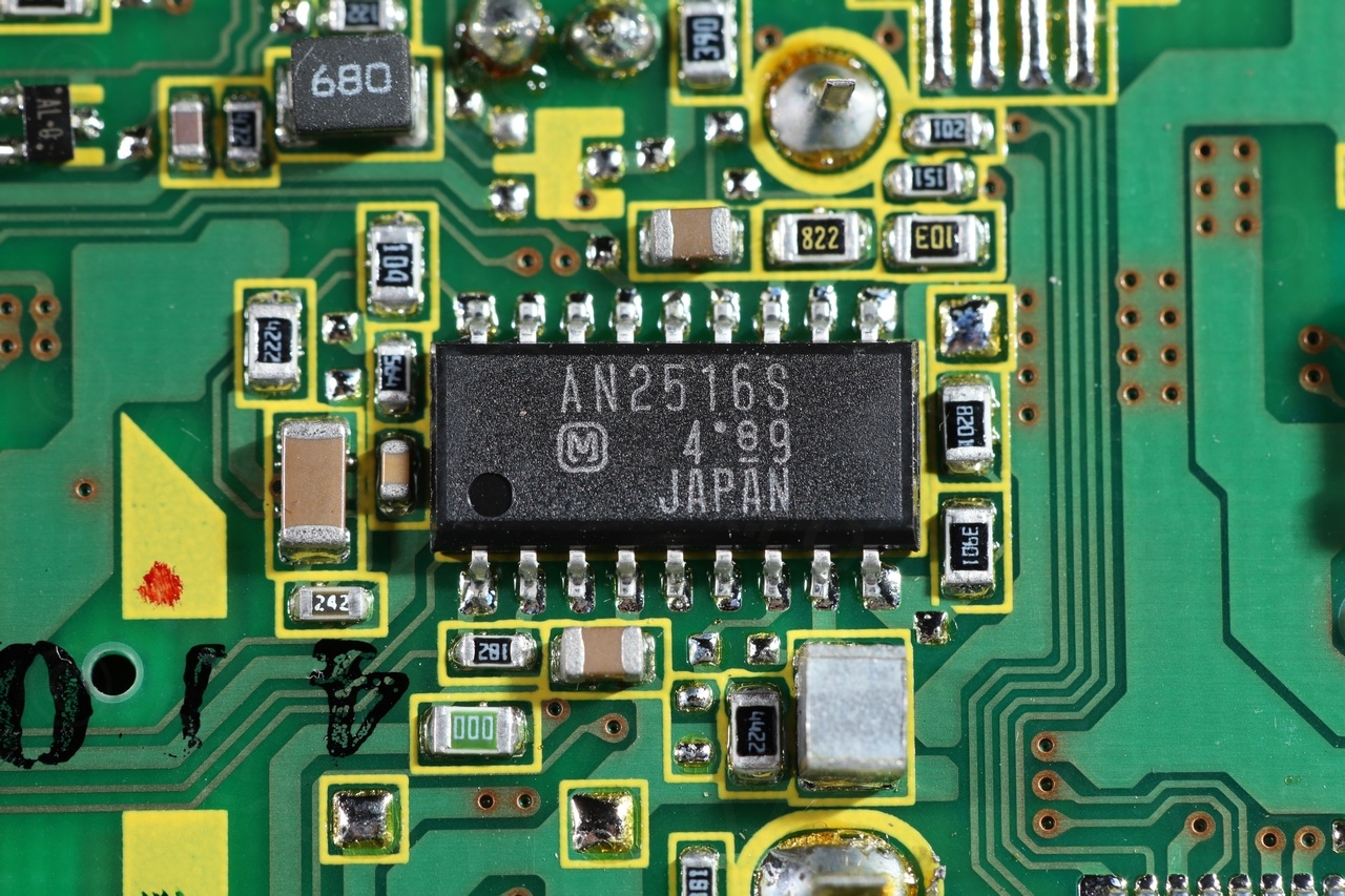
Pin 2 of the IC is VCC, Pin 4 is GND:
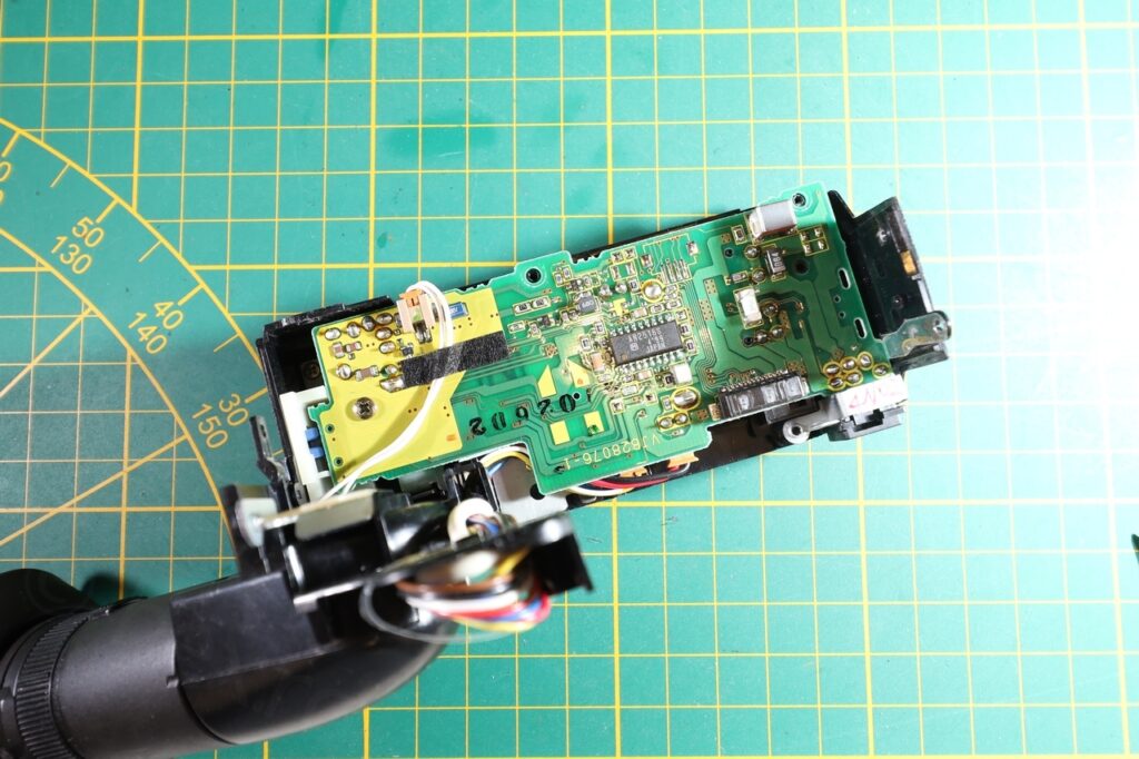
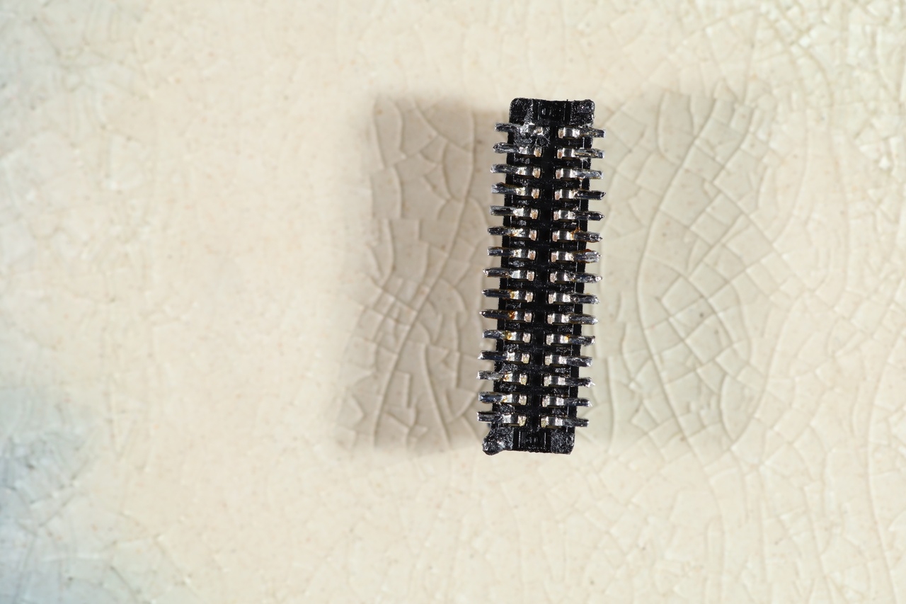
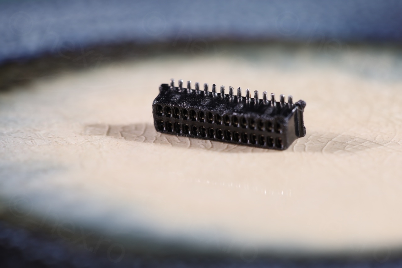
CRT was alive finally, the next step being making it show a real image. This is where things got complicated. I was not able to get it to show an image, even if I did identify a test point where I could provide the EVF Y (Video) signal. I had to desolder the motherboard connector and try to hook some tiny test clamps to it:
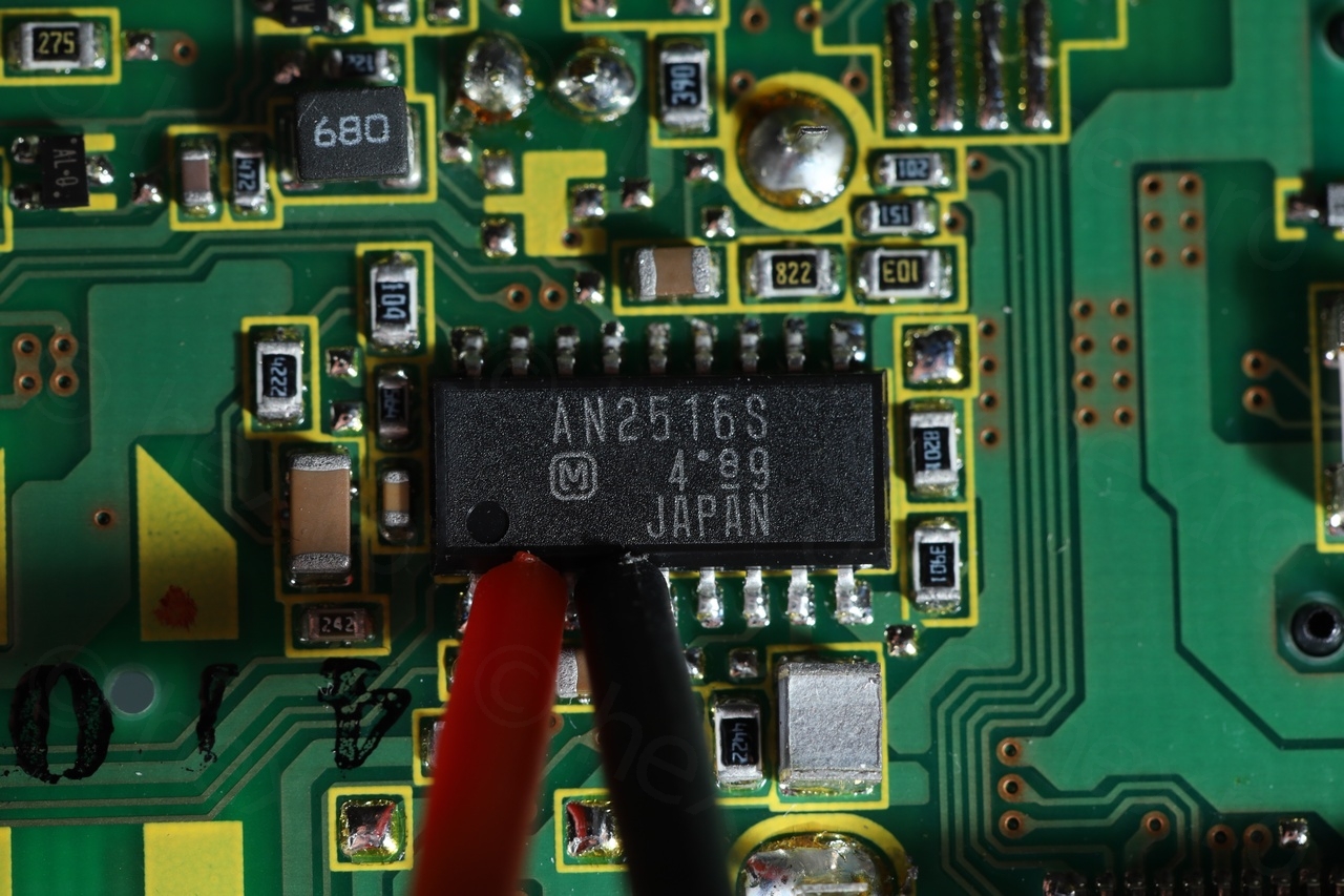
By trial and error, I have identified 2 pins that were having an impact on the image. Pin 7 (EVF Y) but surprisingly, also Pin 12 (MIXR.N.D). This Pin 12 was very puzzling. It was connected to the driver IC directly, on pin 10 of the IC (C MIX):
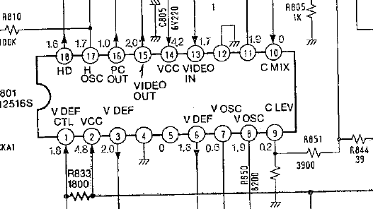
In the schematic of the AN2516S, the recommended test circuit shows C MIX as being connected to GND, but Panasonic decided to route it independently and call it MIX N.R.D ? Very confusing. I was able to locate a different Panasonic schematic which at least clarified that MIX N.R.D stands for Mix Non Rec Data. I thought that maybe the camera had to provide some type of signal, like date or battery level, information that the IC would overlay on top of the ‘Rec Data’ (the Video being recorded).
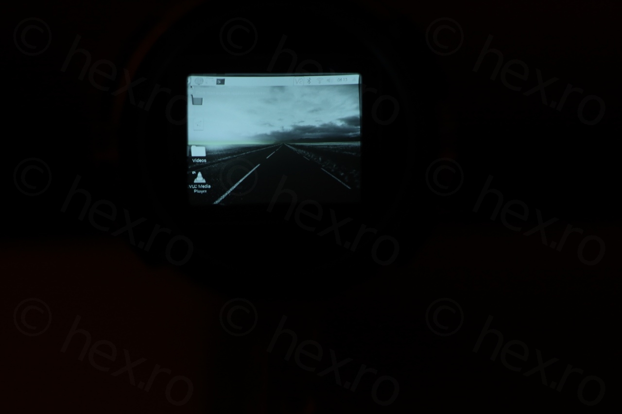
Without it connected to GND, there would be no image on the CRT though, even if Video IN signal was provided to Pin 7 of the camera (EVF Y). Without Video IN also, the CRT would flicker, but with signal present on EVF Y, the CRT stops flickering but shows no image (just white). I switched to NTSC signal and same issue, no flicker but with a black border on the bottom. So the driver IC knows there is a Video signal there, respects it, but shows no image.
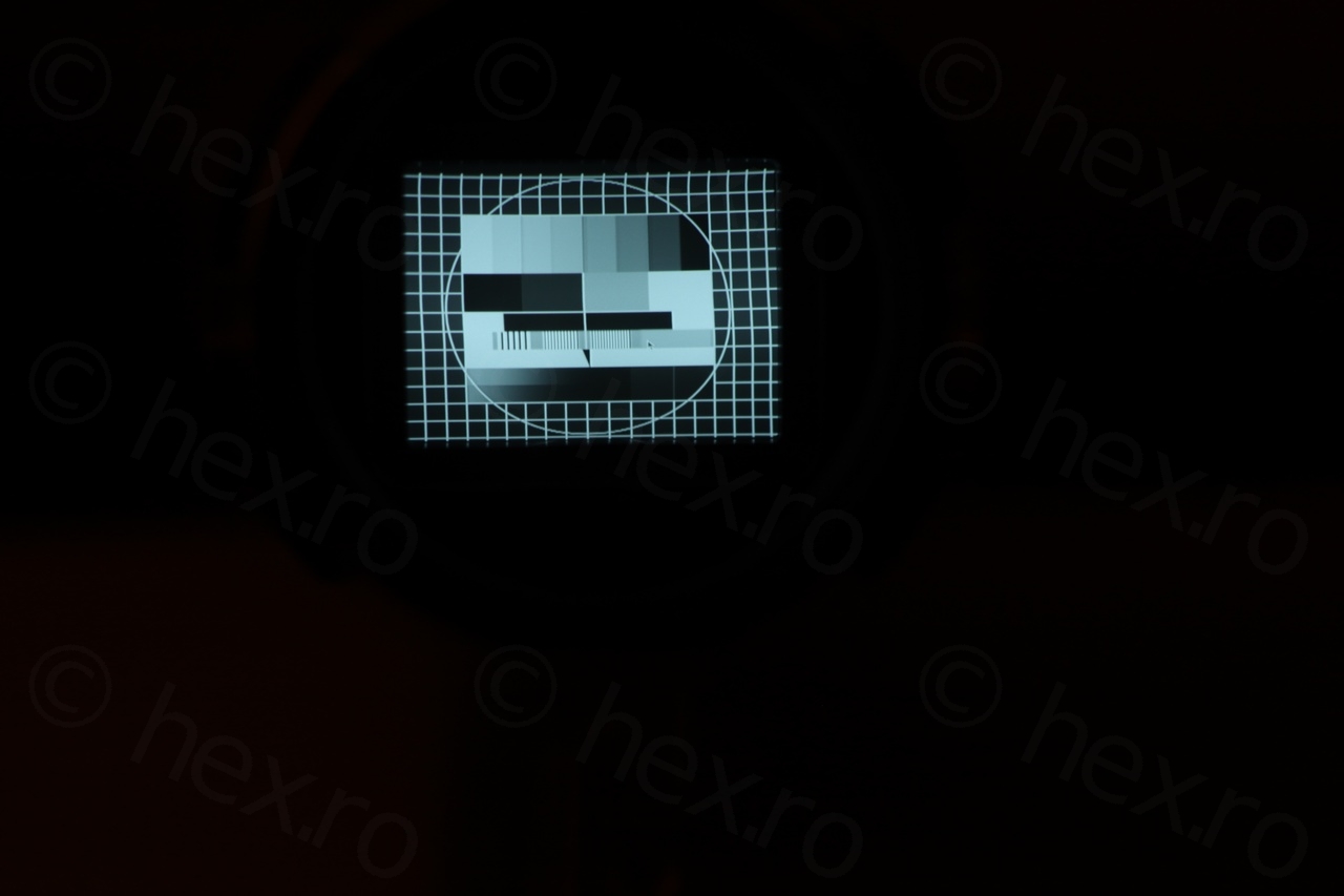
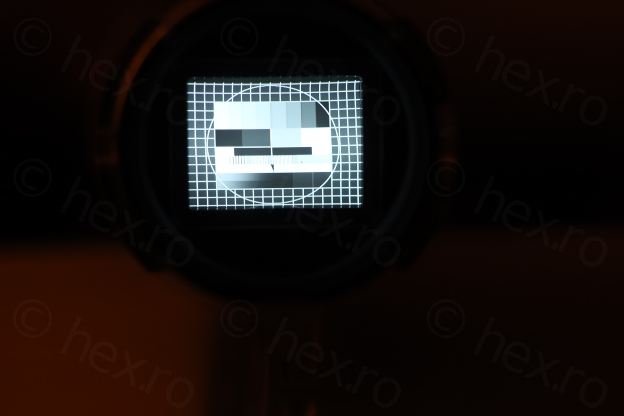
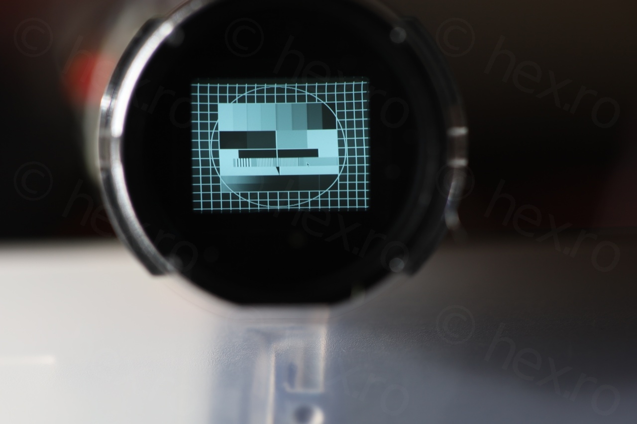
Only after connecting MIX N.R.D to GND I was able to get an image:

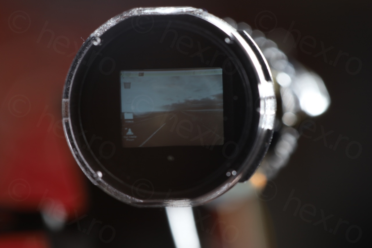
Few close ups with the CRT unit:
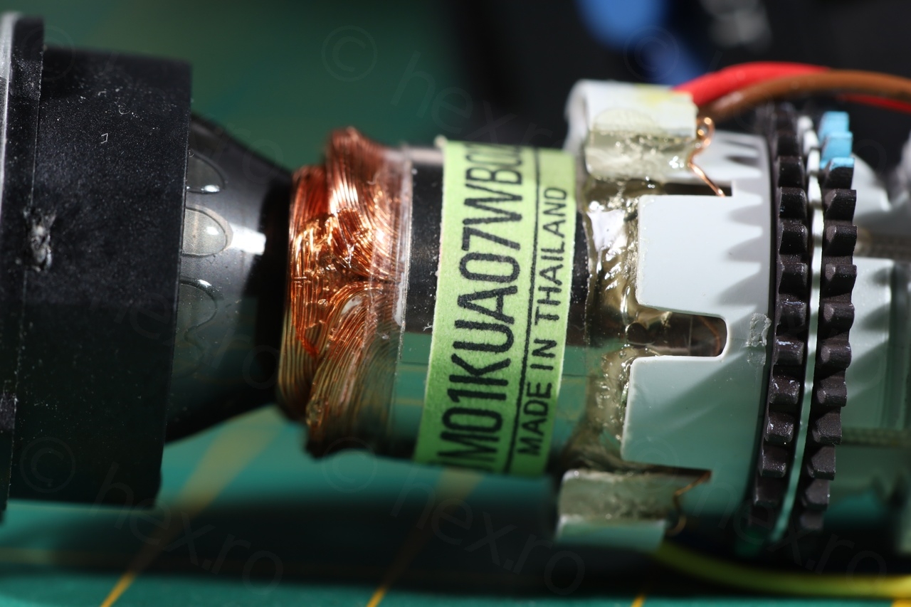
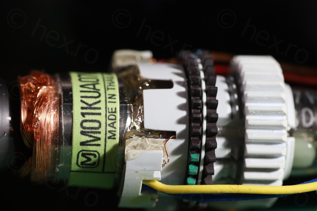
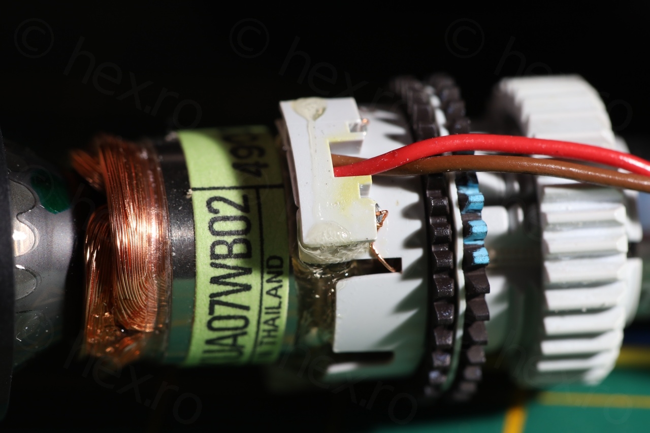
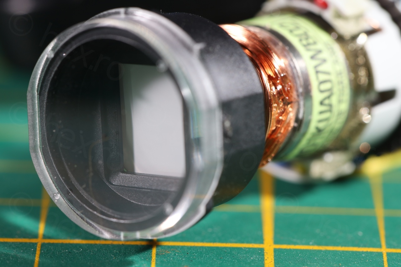
After struggling for a while trying to piece together all the details, the results feel and look good:

I guess by 1994 Panasonic realized that these drivers boards are not so fragile to need servicing often and to house them into the EVF unit for easier replacement.
Tehan
Hi! what is the diagonal length of this crt ?
i am really interested!
Tehan
i ment the diagonal length of the screen
viulian
Hello, I do not know the screen dimensions. And is a challenging task to find this specific CRT in storage..
Tehan
Alright its okay then . but what is the smallest crt you have seen?
is it the M01KUA07WB30 with a diameter of 10.8 mm?