

Introduction
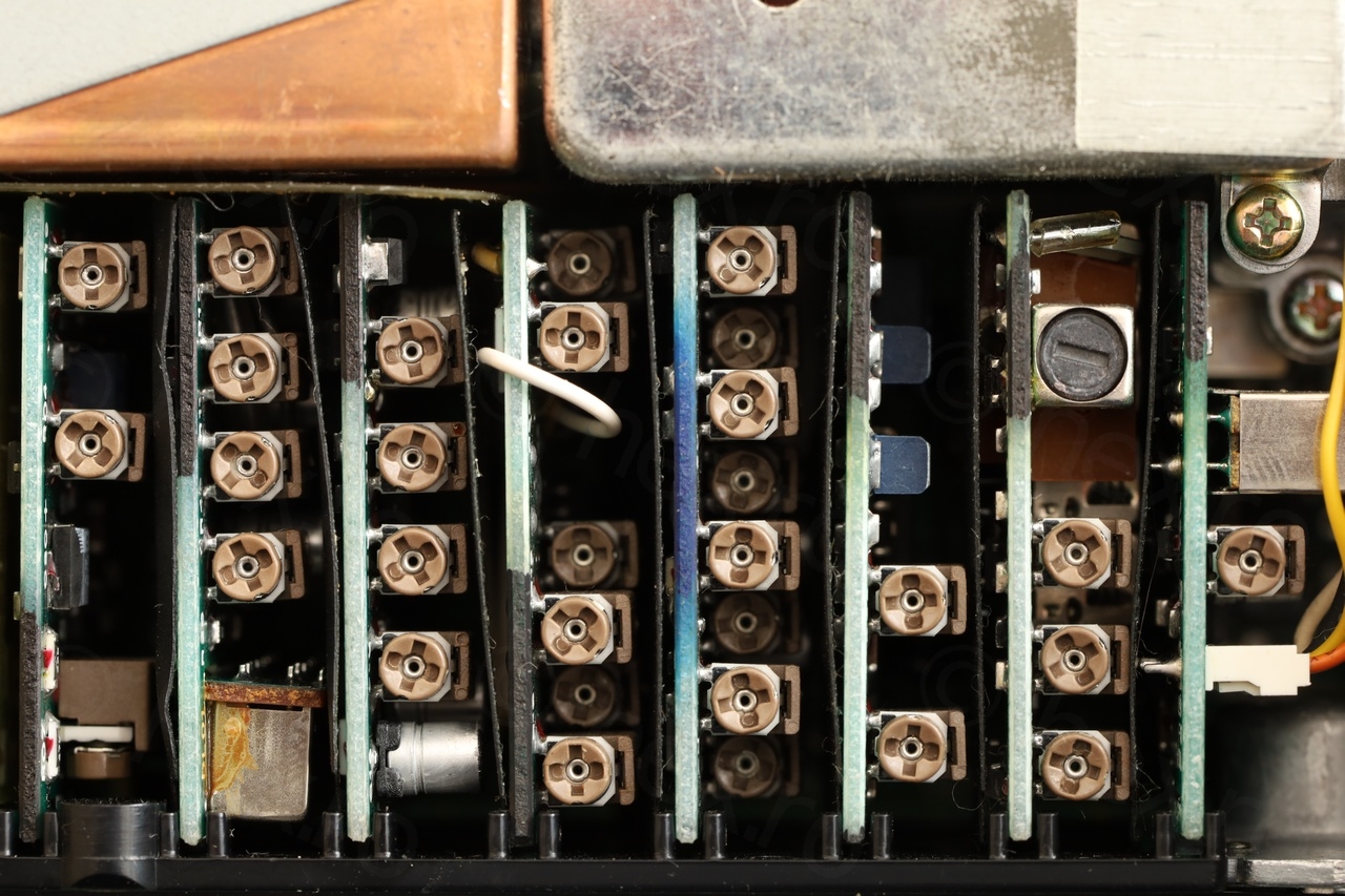
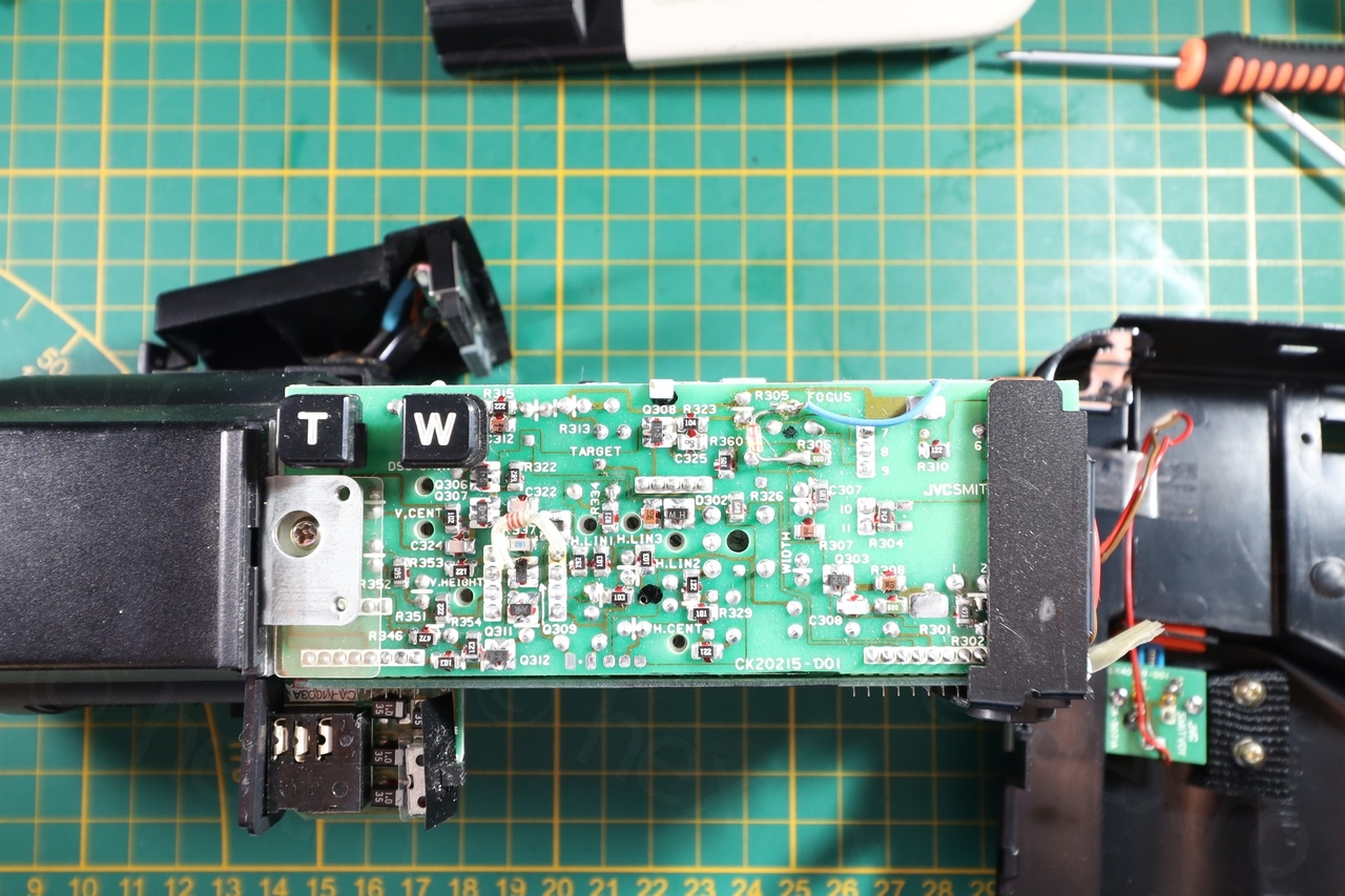
Found this mini CRT inside a JVC GX-N7E camera that I bought at a flea market. Camera was small, compact, sturdy – peeked my curiosity to open it up. Oh, what a surprise inside. It is the most awe inspiring circuit board I have ever seen in a camera, the amount of adjustments is incredible!
Camera
A global overview of the camera:
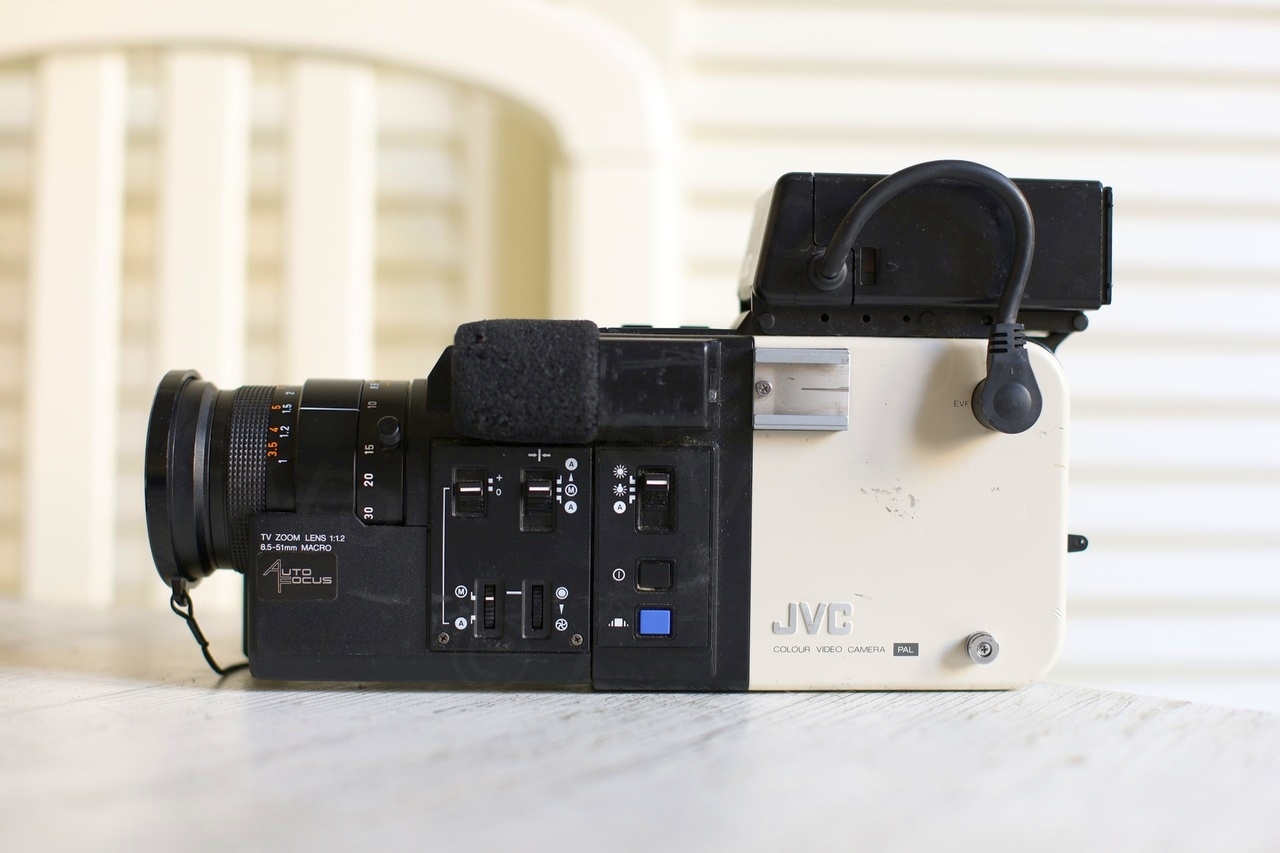
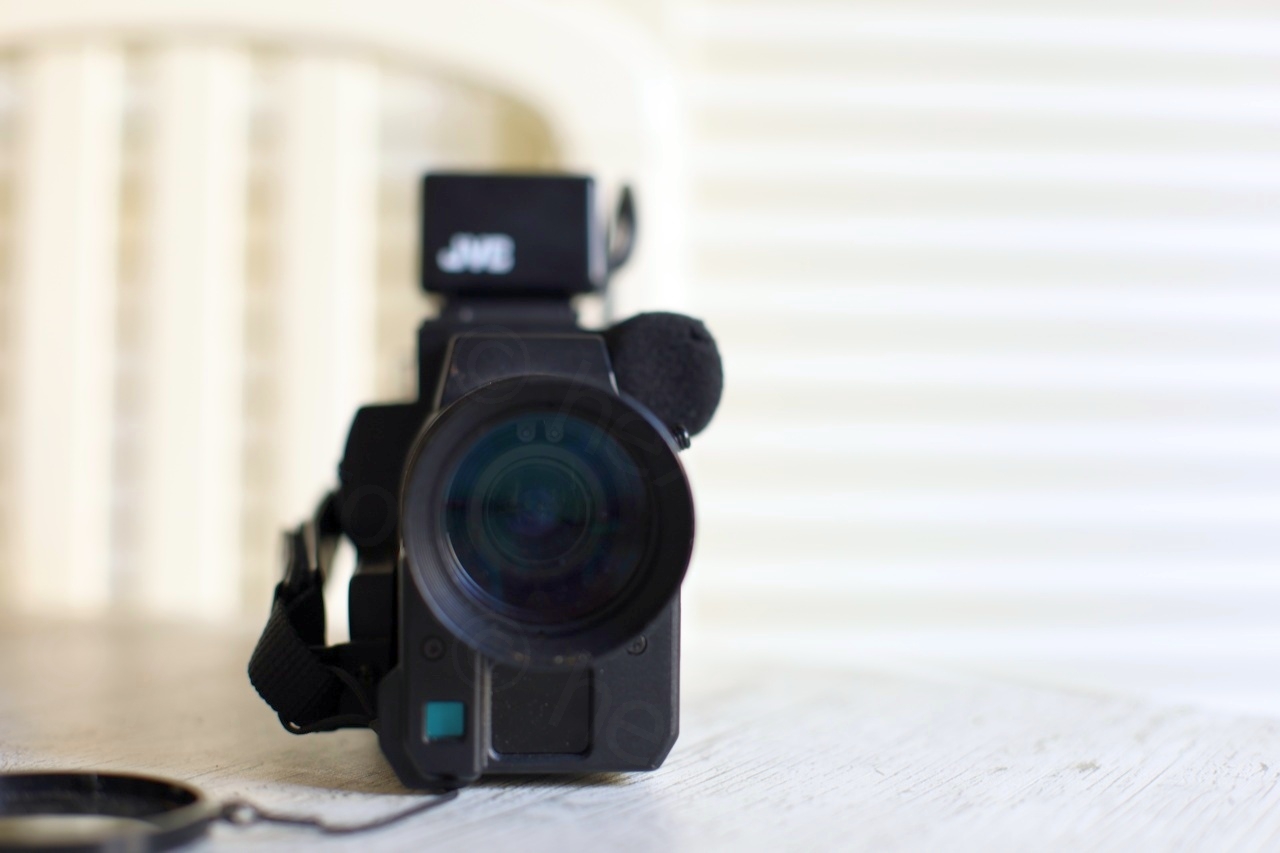
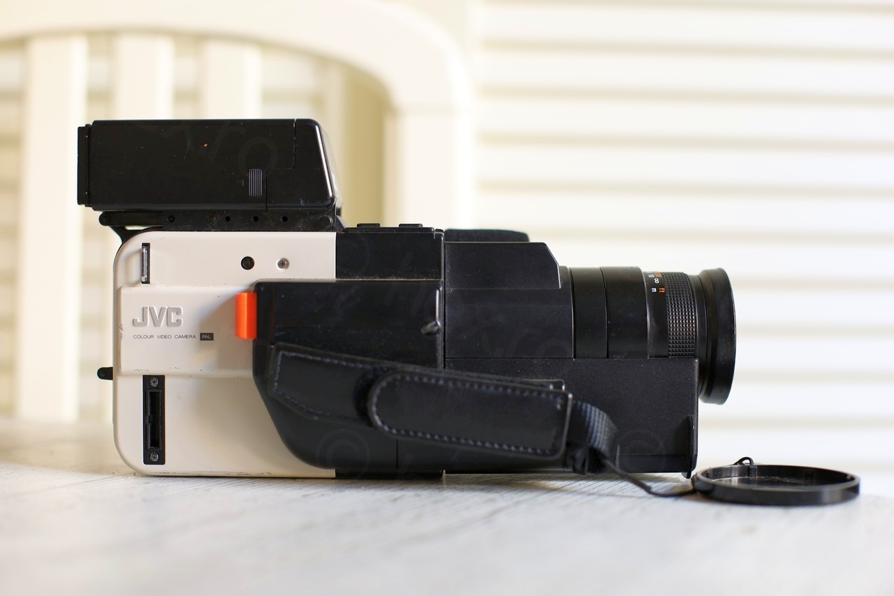
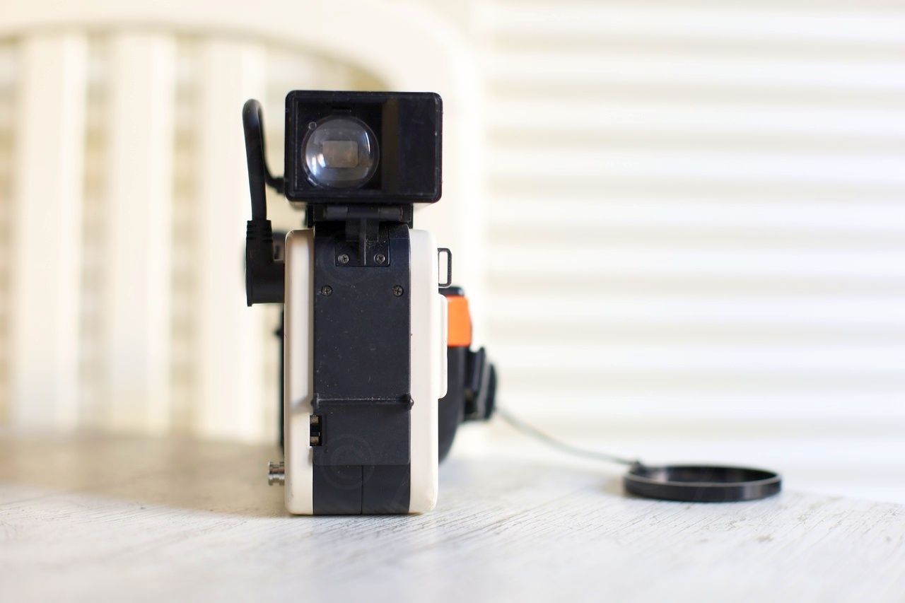
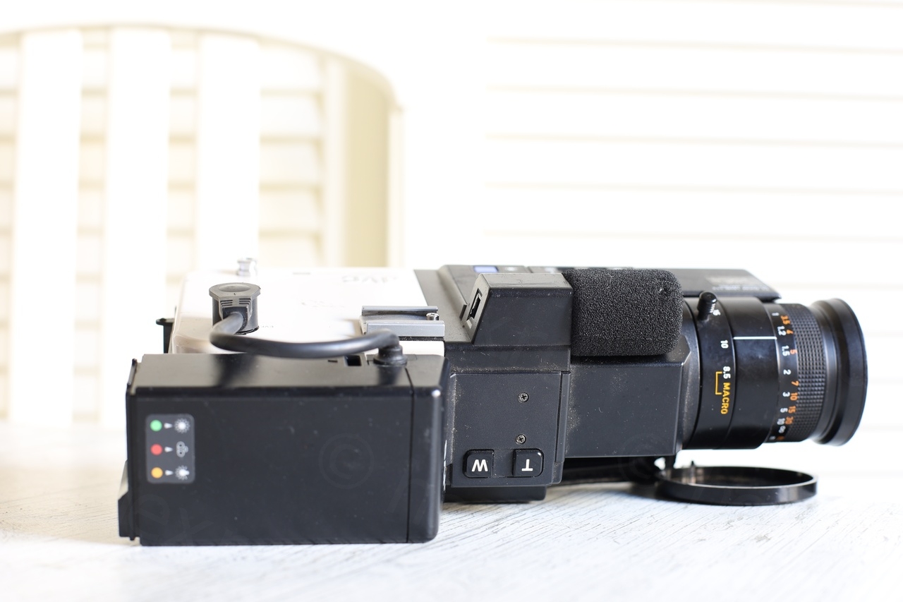
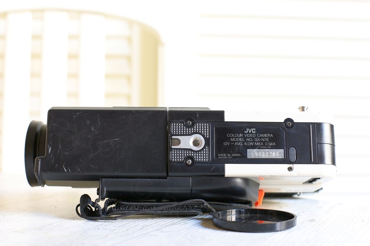
The view finder was missing the eye piece and also there were few dents here and there on the camera body. However, the windscreen on the microphone was still intact when cameras this age (1985) never have intact windscreen so I was already impressed.
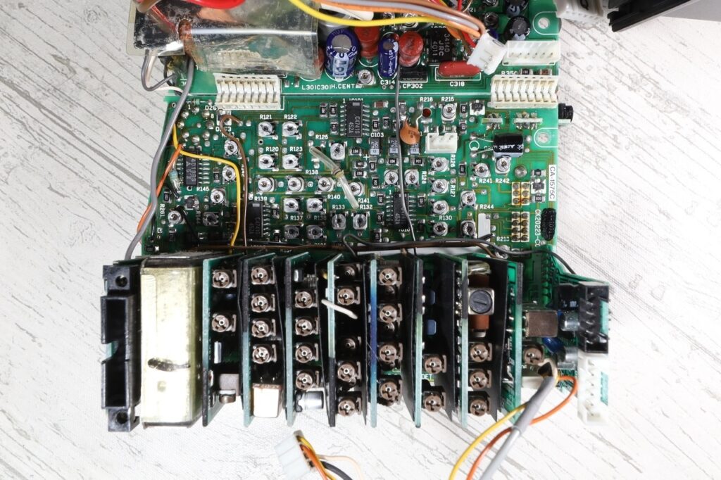
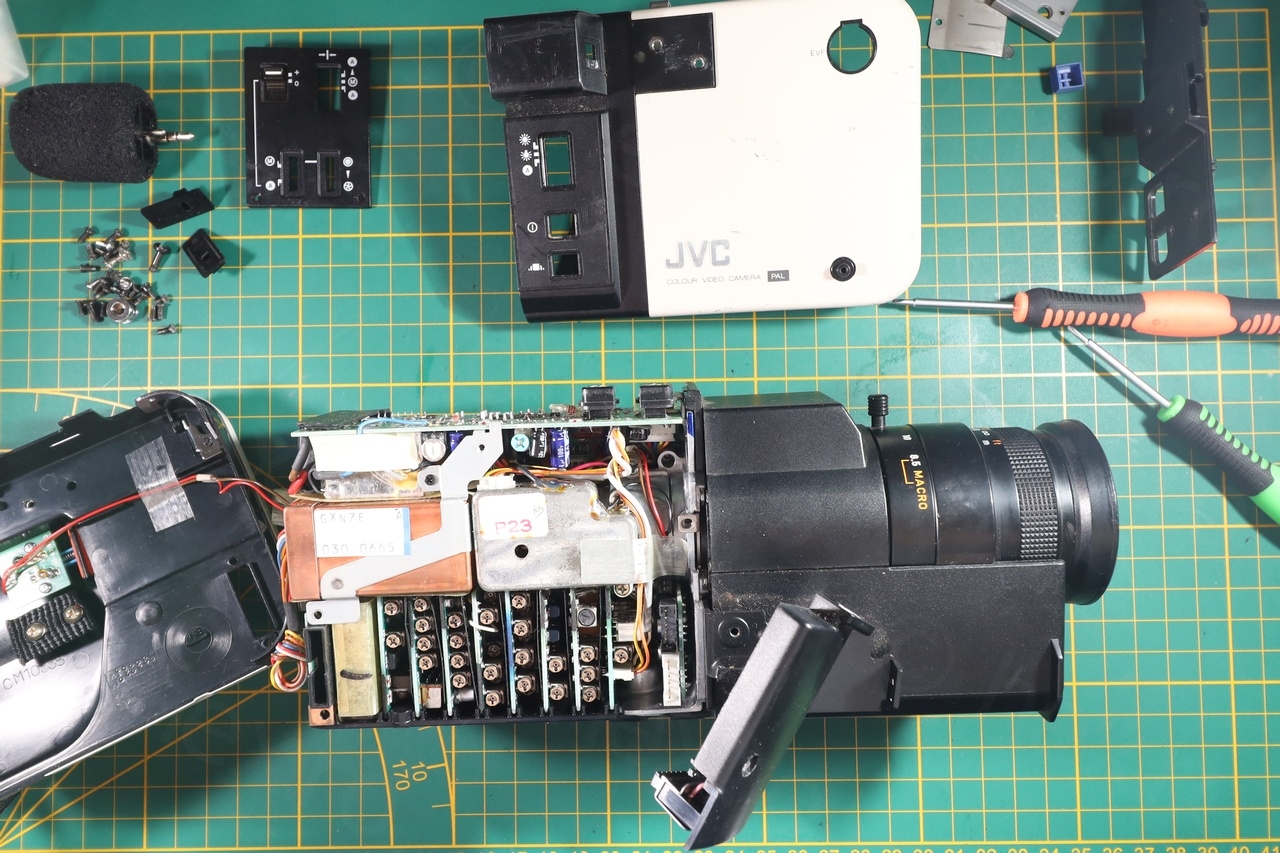
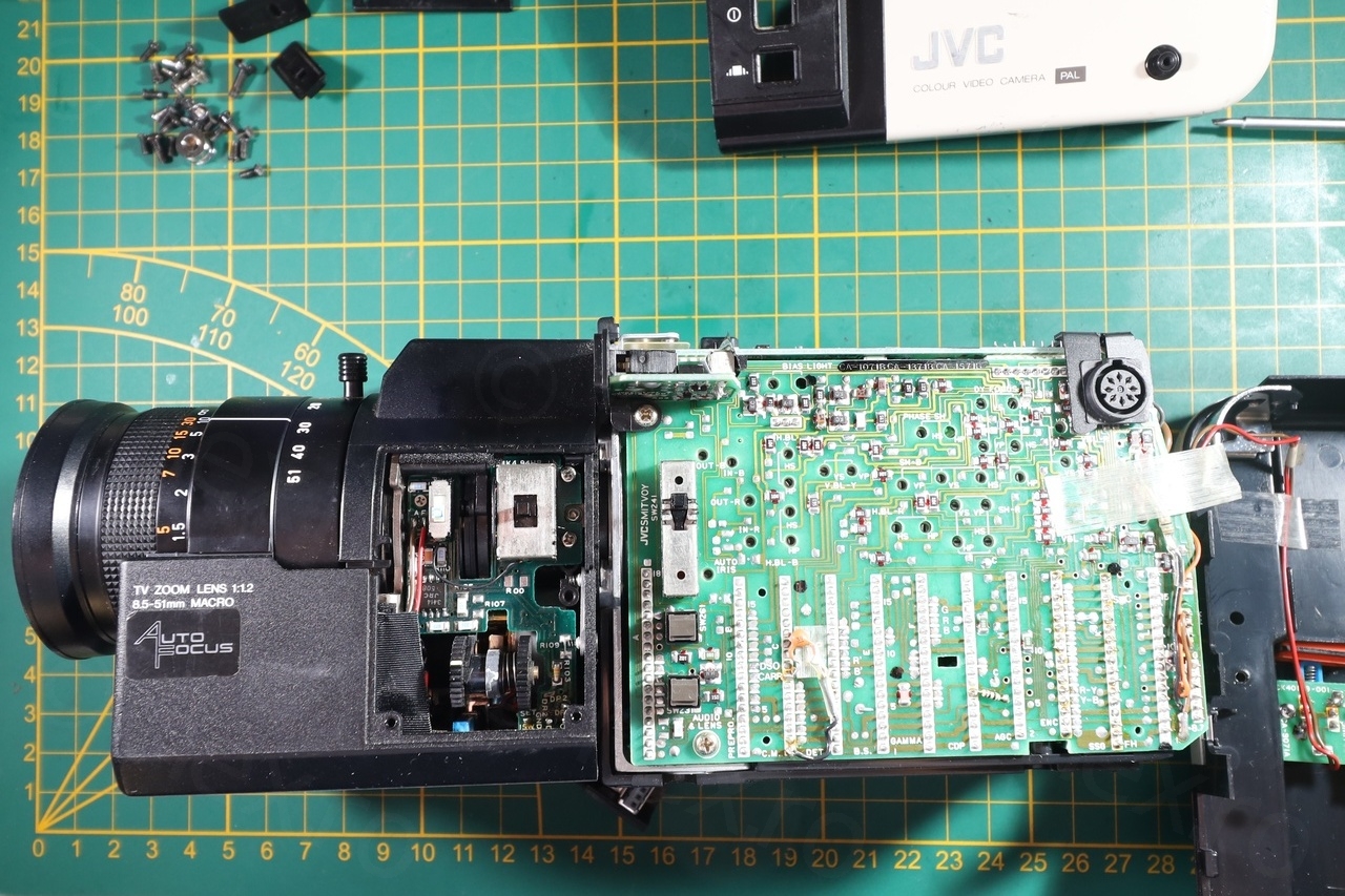
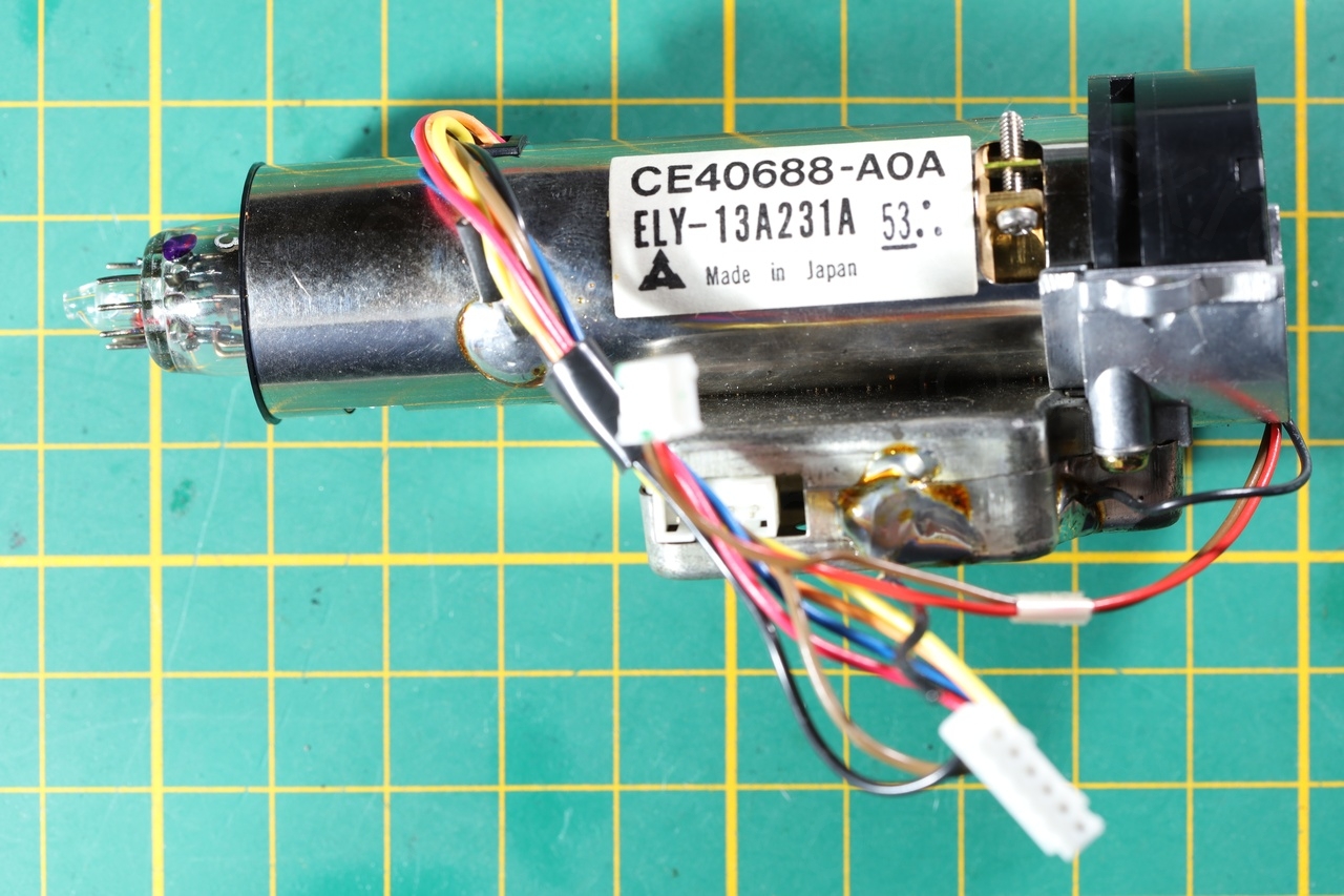
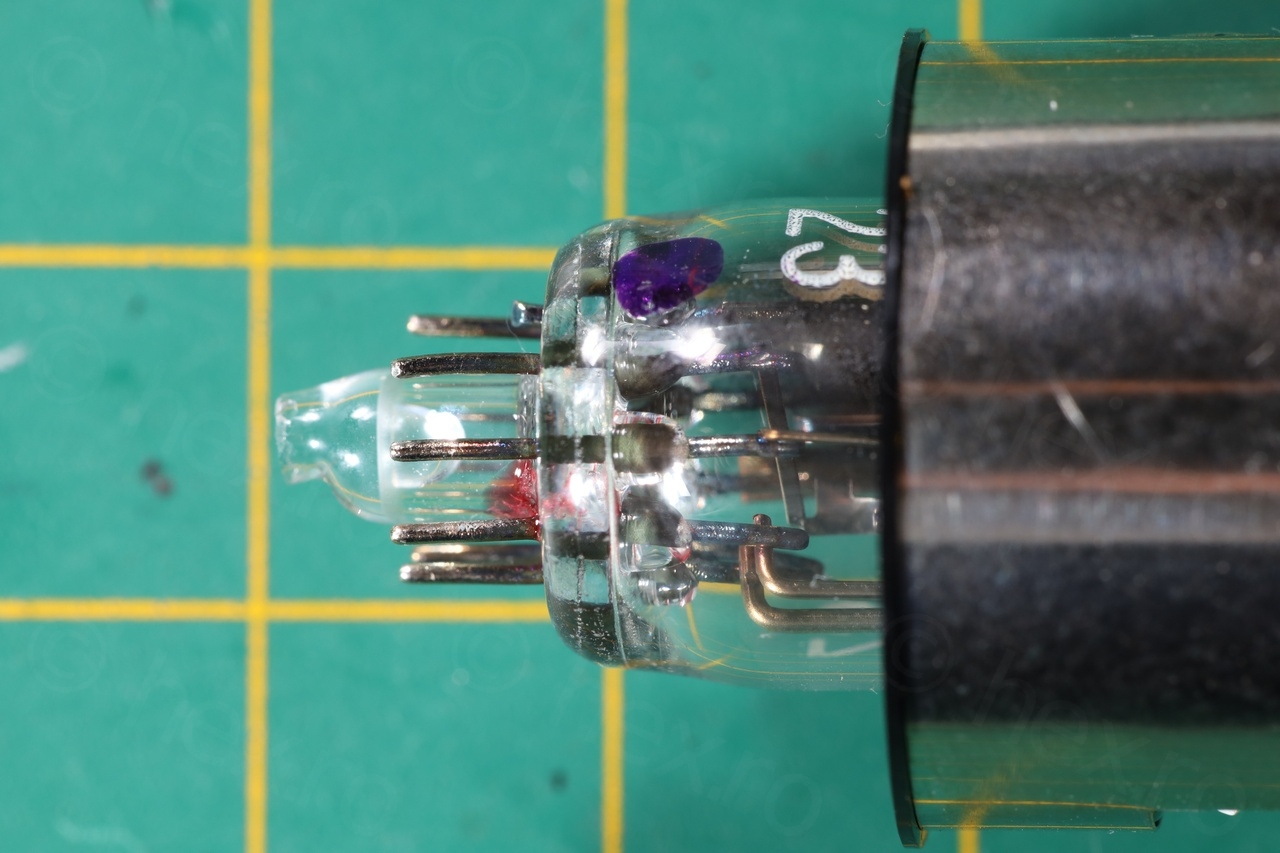
I proceeded to take it apart, revealing a very dense interior as well as a sensor tube instead of a CCD. I decided to keep the tube, but not its circuitry, I will probably never use it ..

And two photos with the imaging sensor:
Since there was nothing else interesting in the camera, I have proceeded to try to see if I can figure out how to power on the Electronic View Finder.
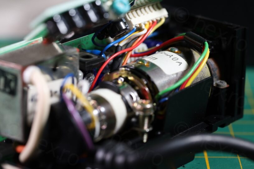
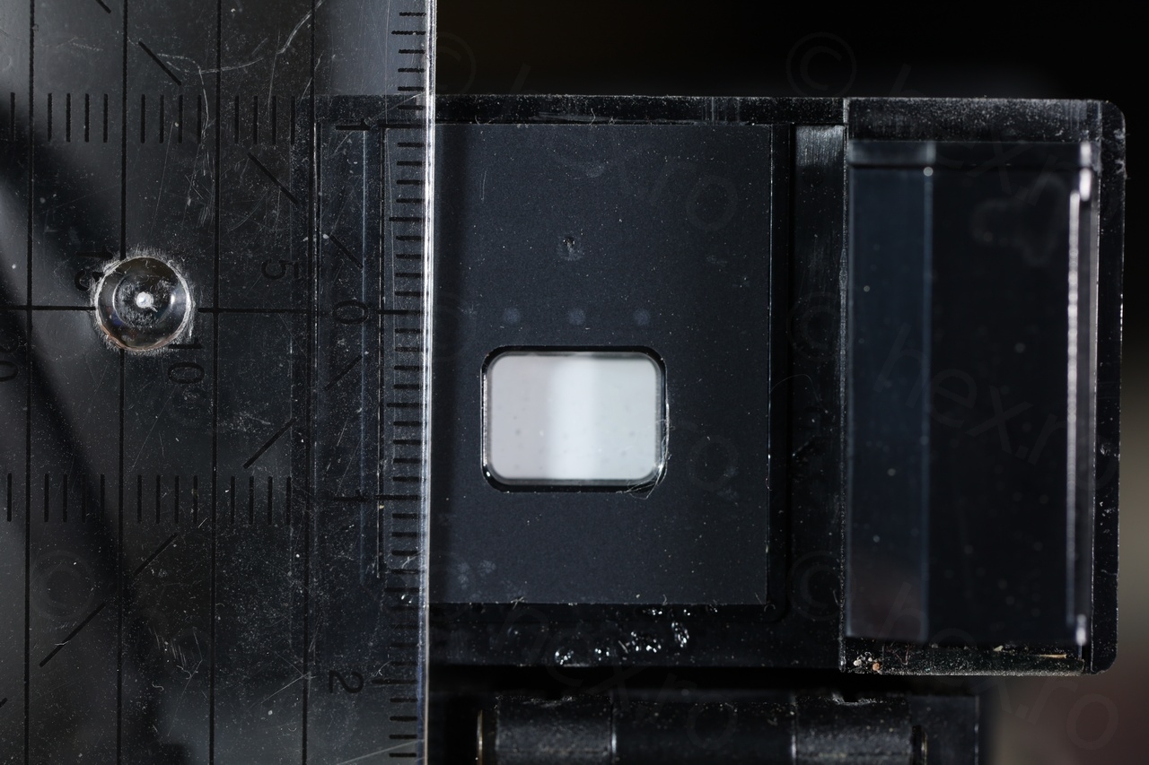
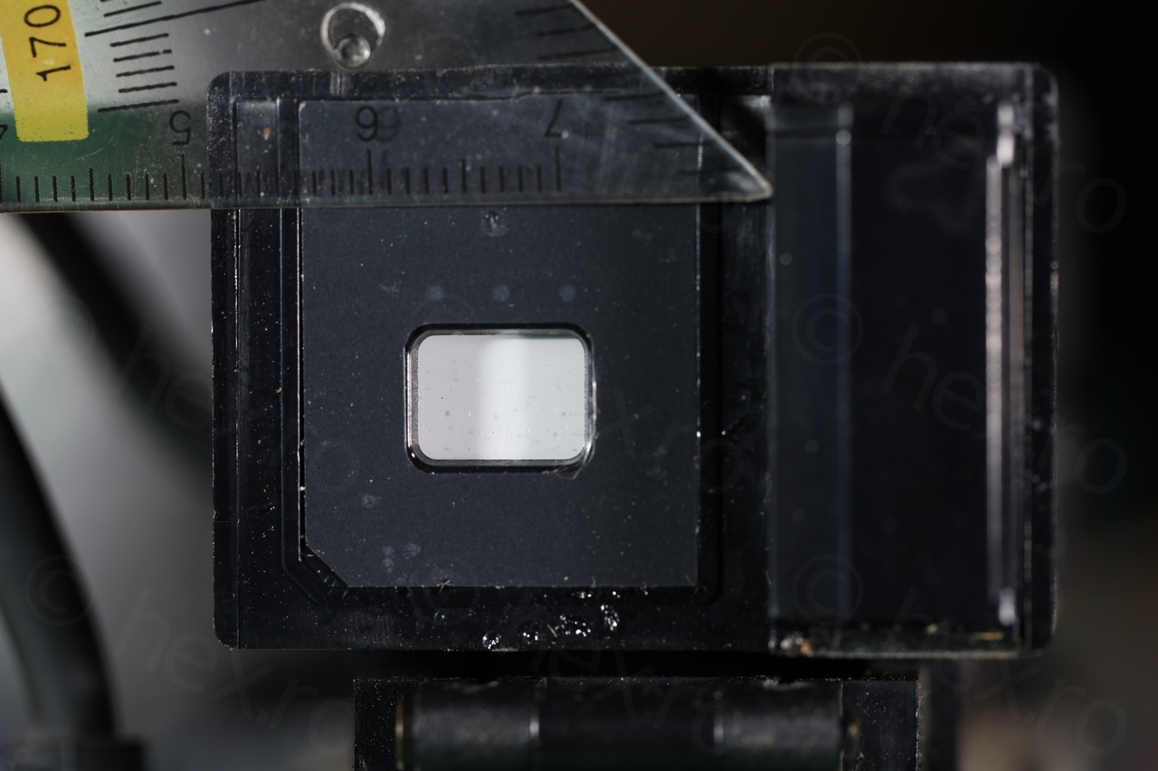
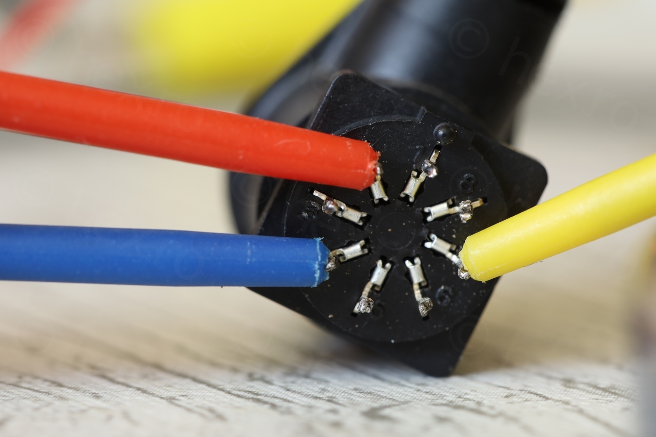
It seemed easy, an external EVF with accessible wiring, except I had to recuperate the plug from inside so that I could inject signals easier with my probes. The visible size is approx 9.5mm x 7mm – another surprising attribute, as I was not expecting such “compactness” from such an old camera:
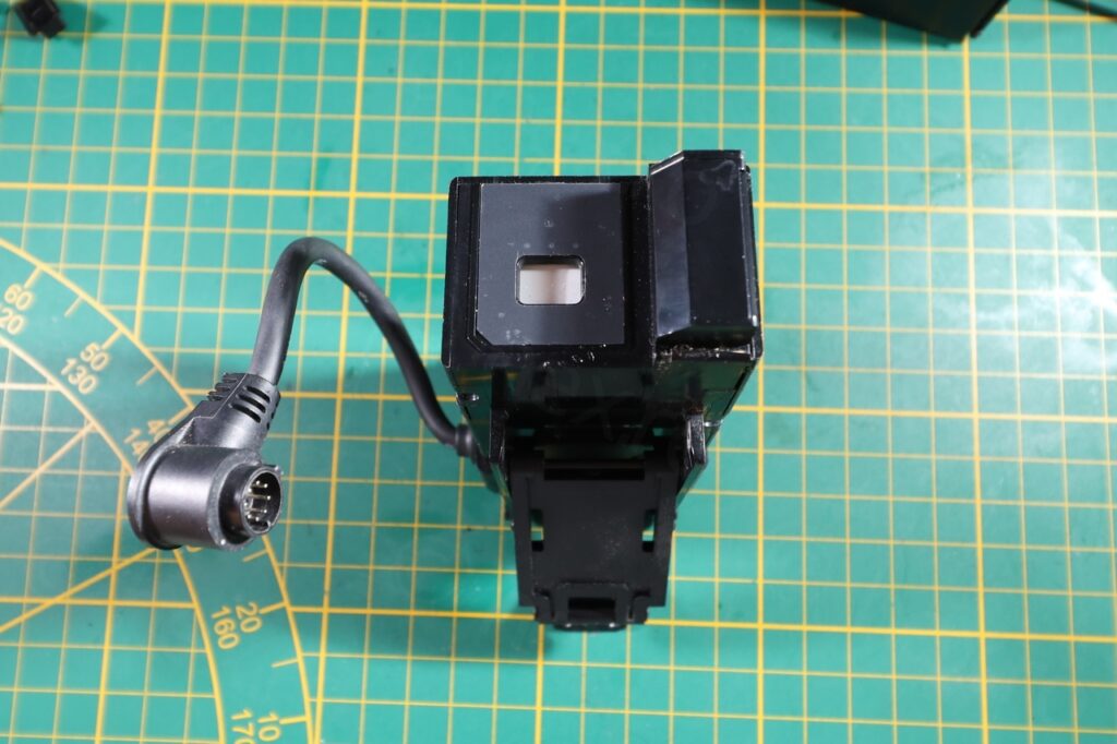
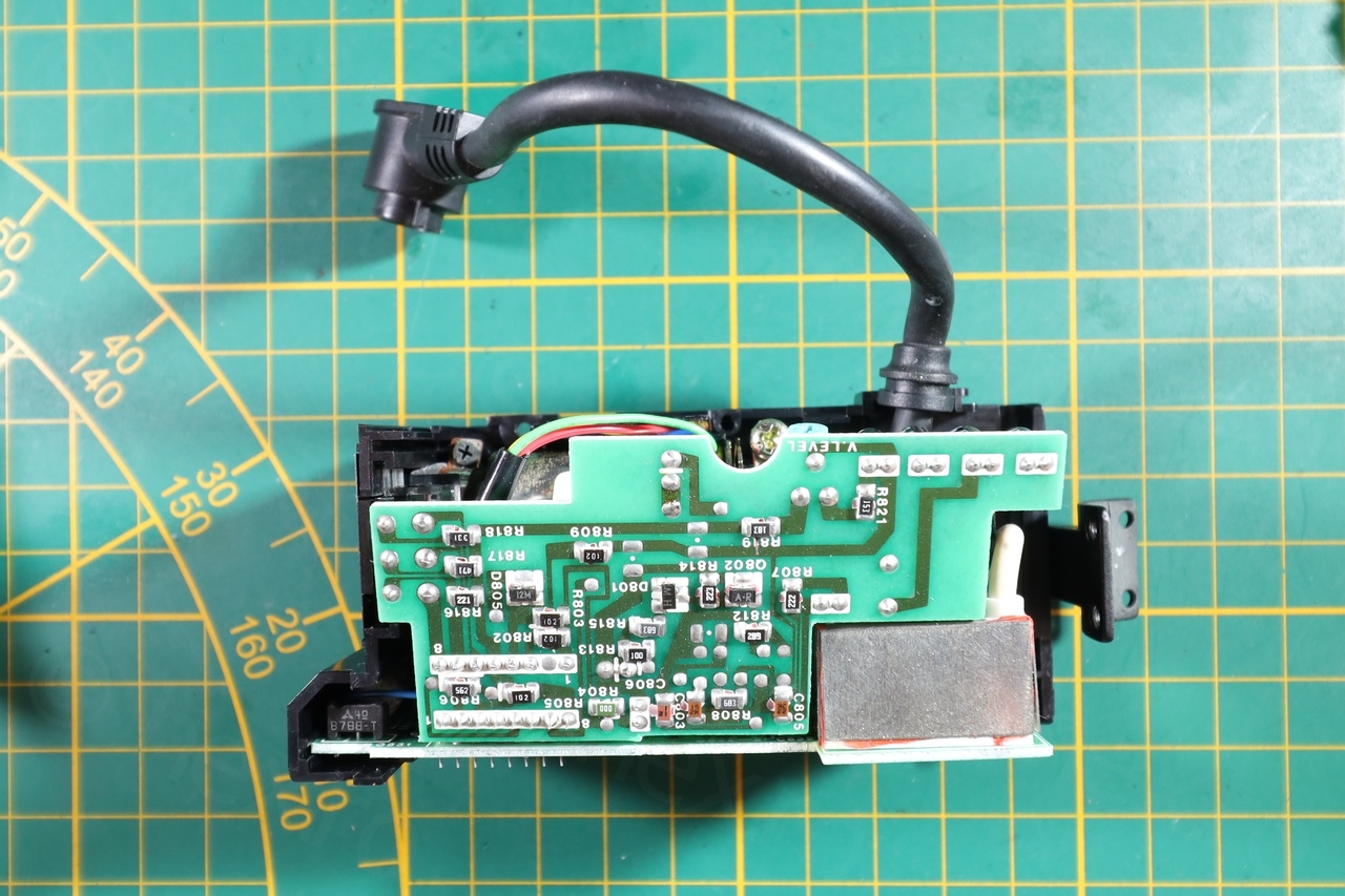
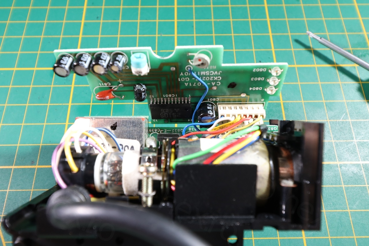
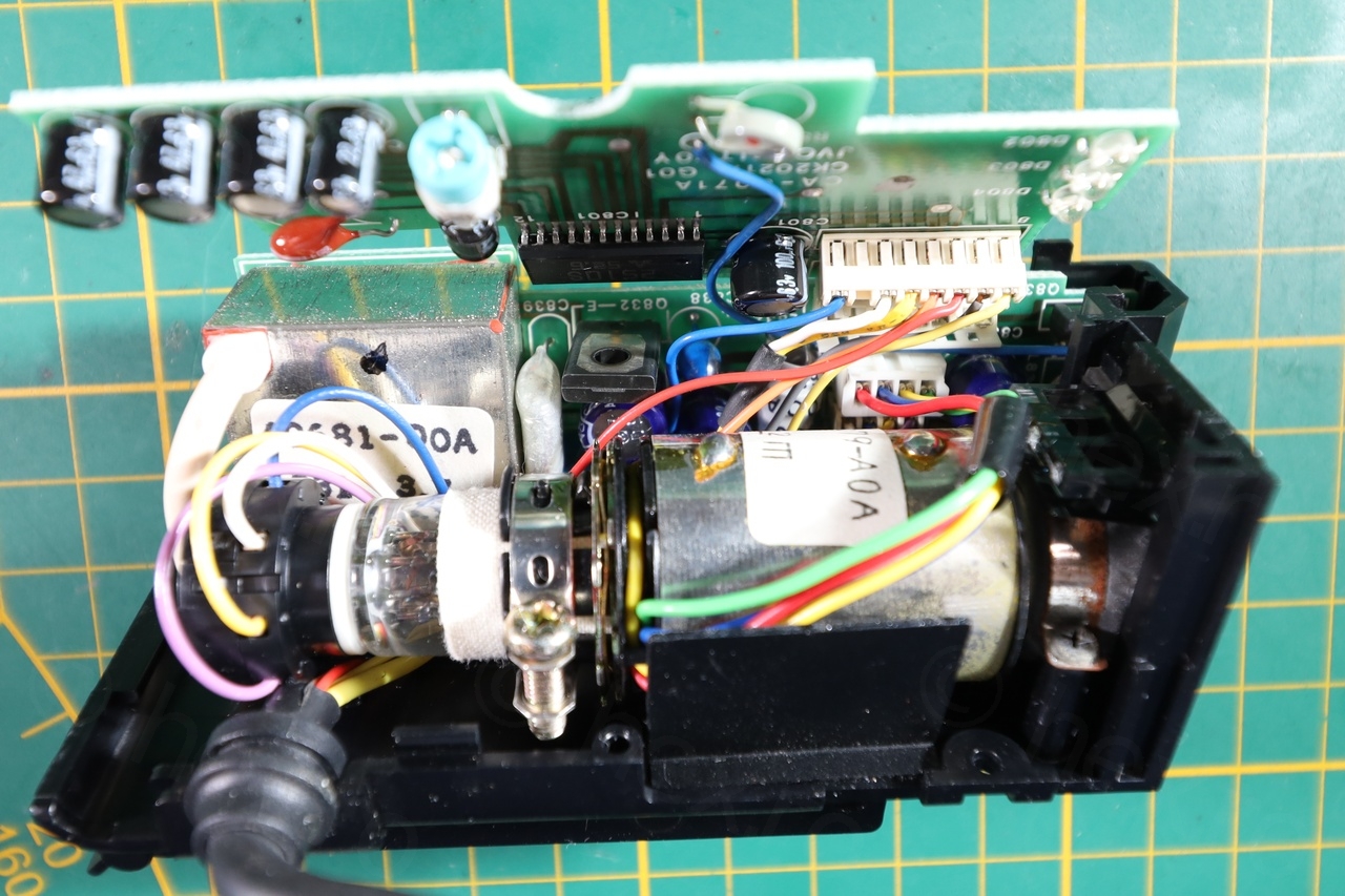
Few more photos with the insides of the EVF unit:
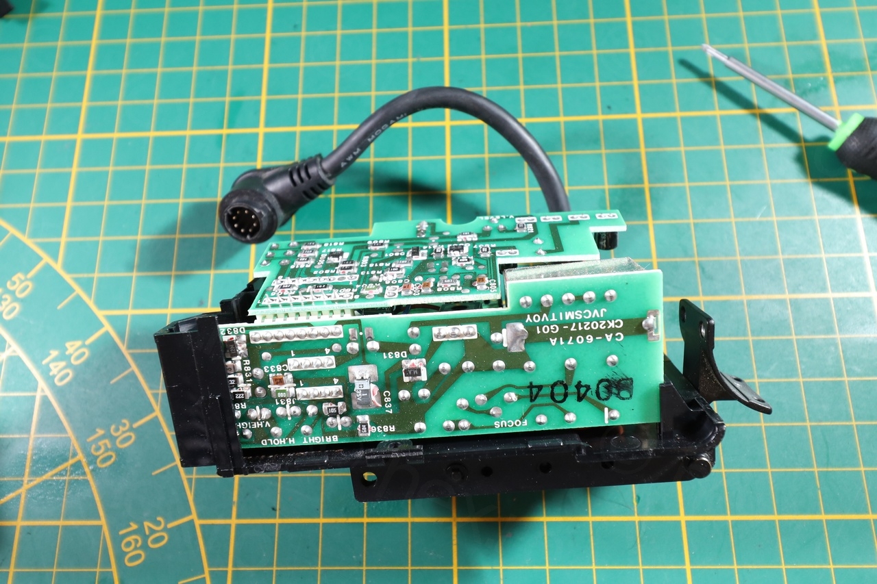
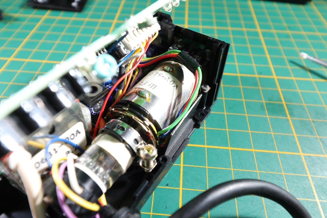
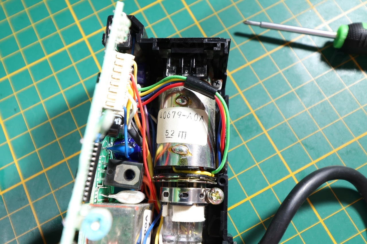
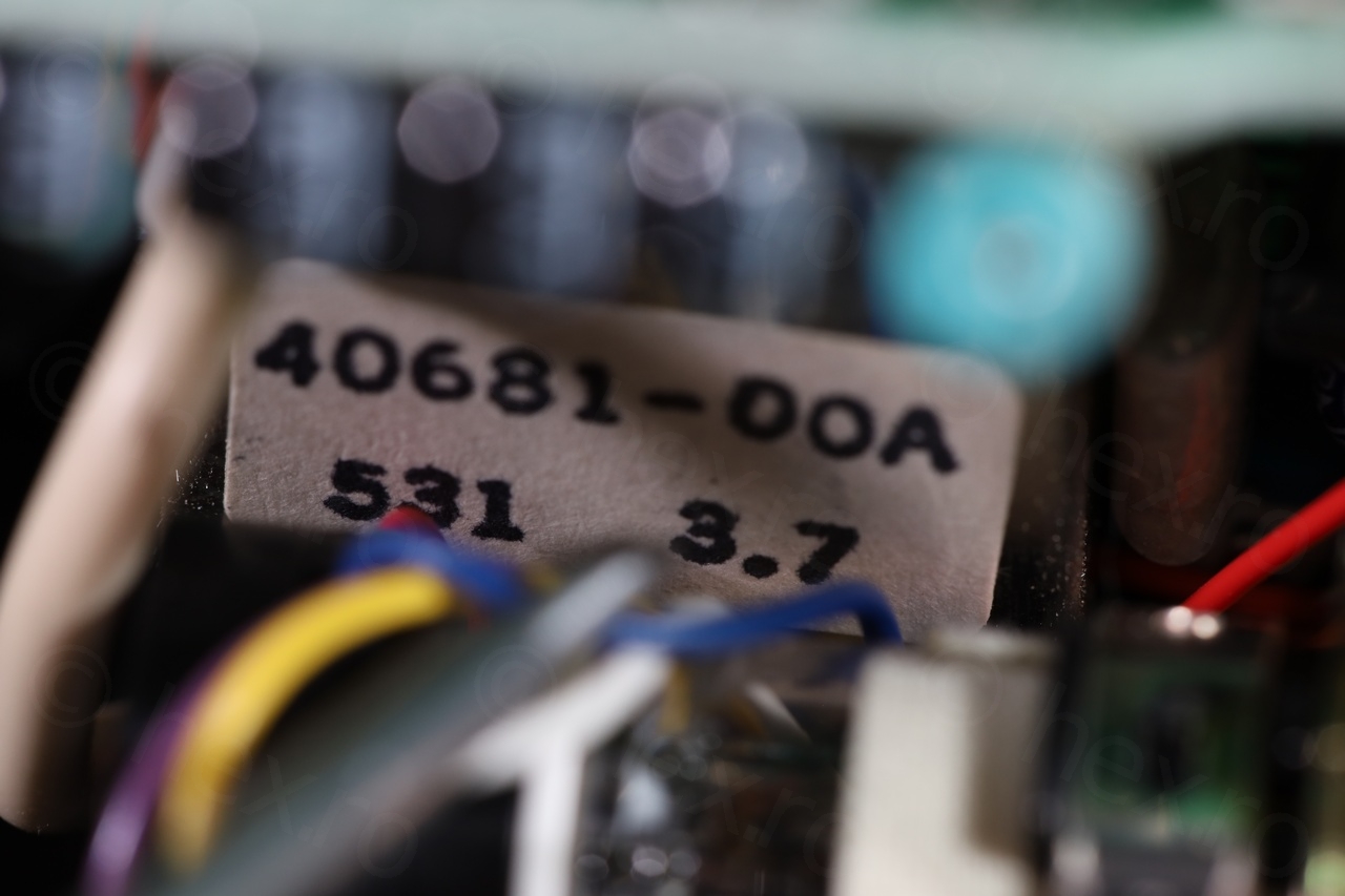

An interesting observation is that the service manual of the JVC GX-N7E calls the CRT as M01JGU9WB even if the part itself in camera is labeled 40679-A0A. Since for example the Flyback Transfomer is called 40681-00A, this naming seems more specific to catalog numbers to order spares, instead of the itself.
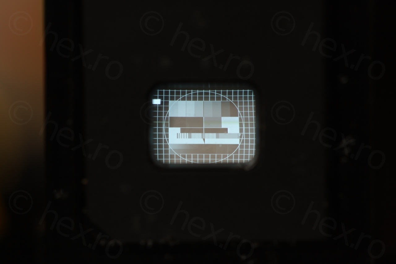
To identify which are the input signals (Video, GND and VCC) I followed the same pattern: GND is connected to the external case of the FBT. Some more pins of the FBT are connected to GND, but some others – if they have direct connection to the plug, they are VCC. Then trial and error for the Video In signal (provided by a Raspberry PI) until an image appears:
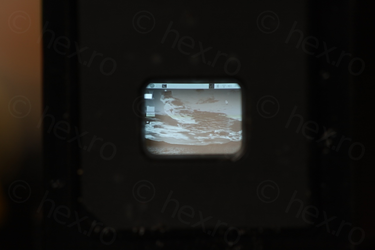
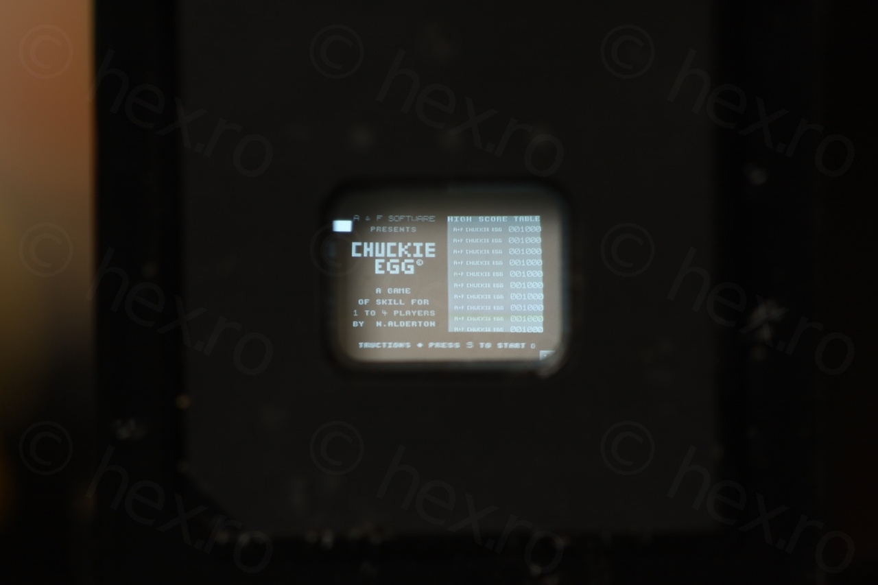
Finally, I had an image on the screen, which is very sharp and well defined.
As I have encountered the left slider as a brightness indicator in other camera, I went ahead and checked which pin is responsible with its control, as well as charting all the other pins from the connector. The full table is below:
| PIN | Function | Observations | ||
| 1 | Green LED | |||
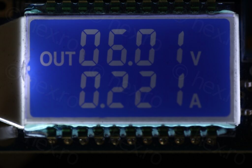
| 2 | VCC | 6V has the sharpest image | ||
| 3 | ||||
| 4 | GND | |||
| 5 | Red LED | |||
| 6 | Slider | to GND it goes down / to VCC it goes Up | ||
| 7 | Video IN | |||
| 8 | Orange LED |
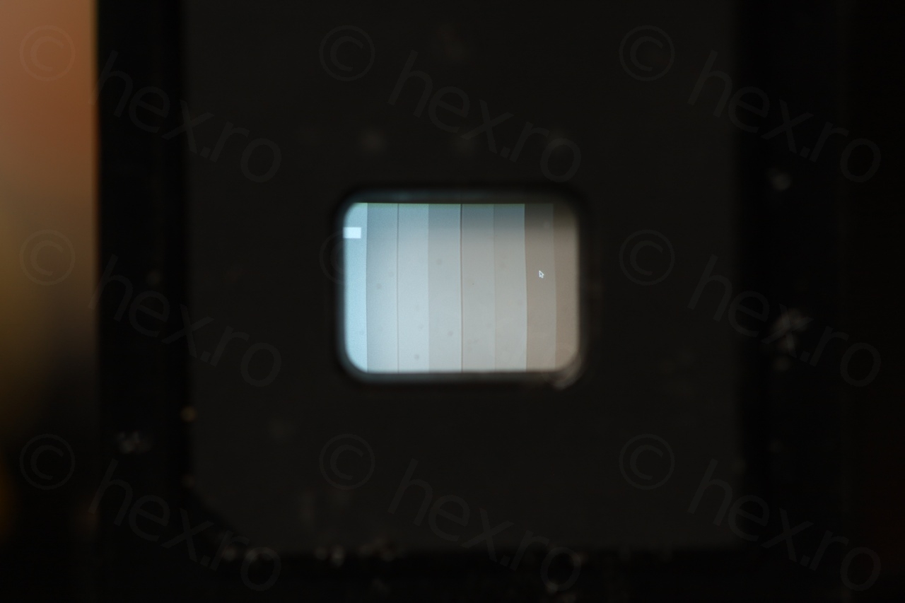
Usually I start the Vcc at 5V and fiddle a bit until I get the sharpest image. Noticed this EVF shows the sharpest image at 6V, and it draws about 220mA:
This camera impressed my by its build quality and attention to detail – sans too many “smart ICs”, with analog control with a lot of calibration potentiometers – not to mention the CRT sharpness – I assume it must have been expensive when new.
As a final test, I decided to play a small game of Manic Miner 🙂
(Photos / Video taken with Canon RP + Canon 100mm Macro at closest focusing distance)
Leave a Reply