

Introduction
I found this mini CRT in a Canon EX1HiE Camera I picked up at a flea market. The electrolytic capacitors all leaked and the board almost had a ‘creme caramel’ color.
Camera
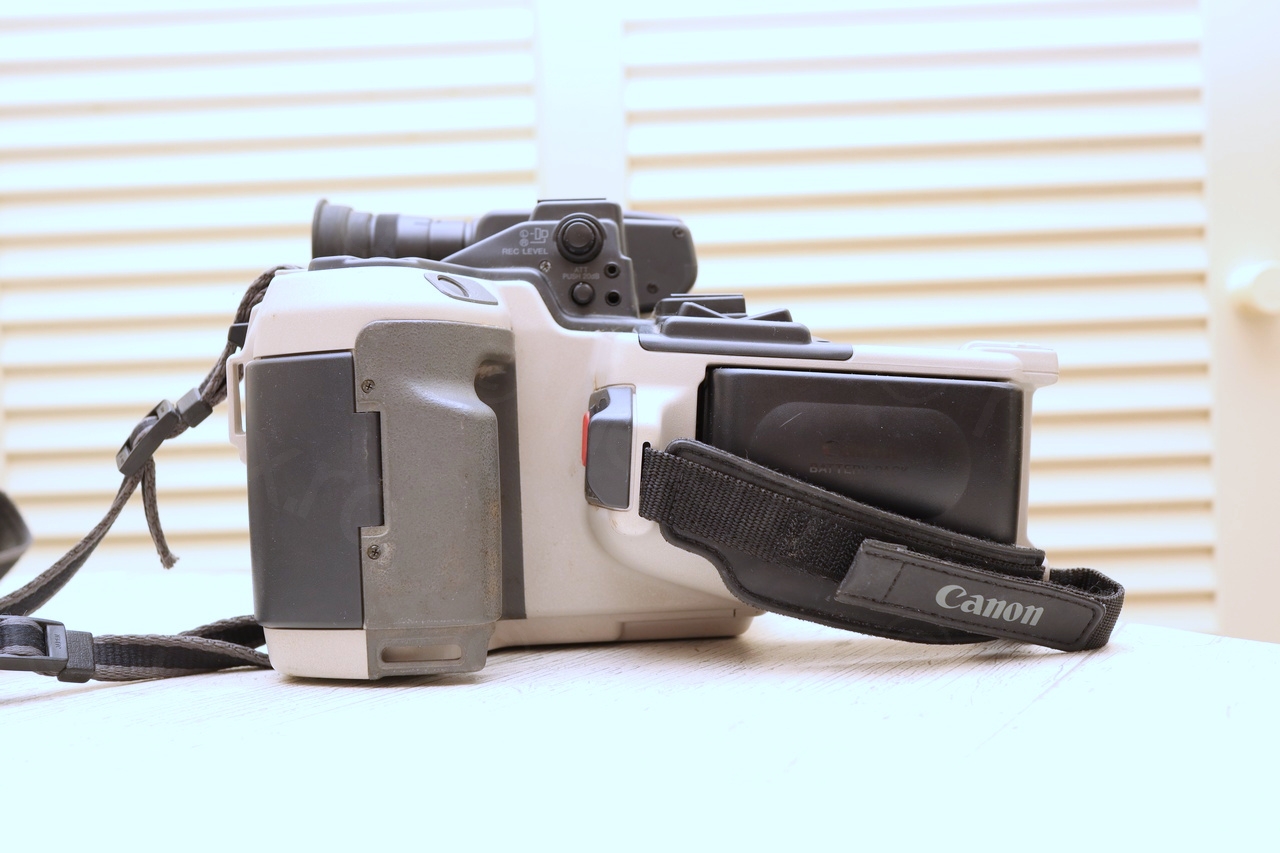
Few shots of the camera before disassembly:


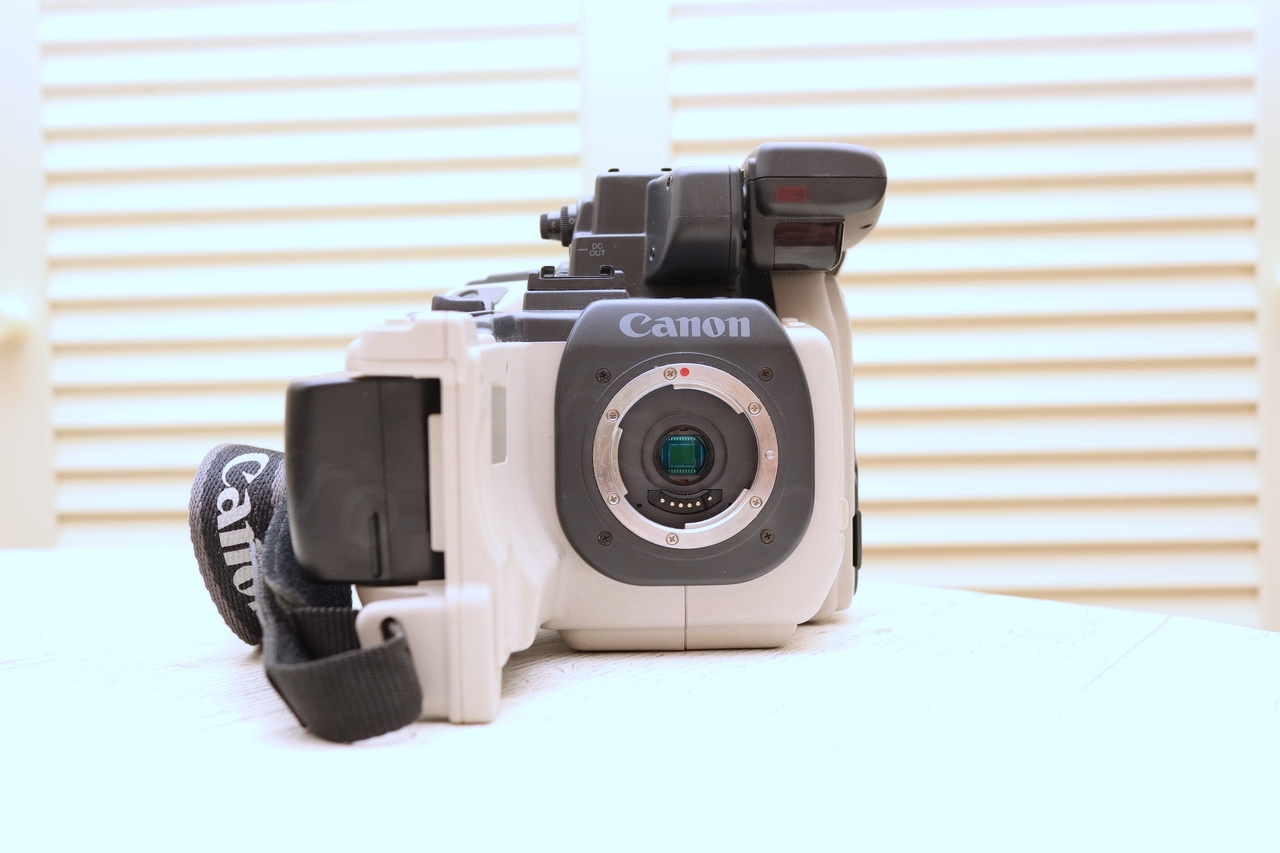
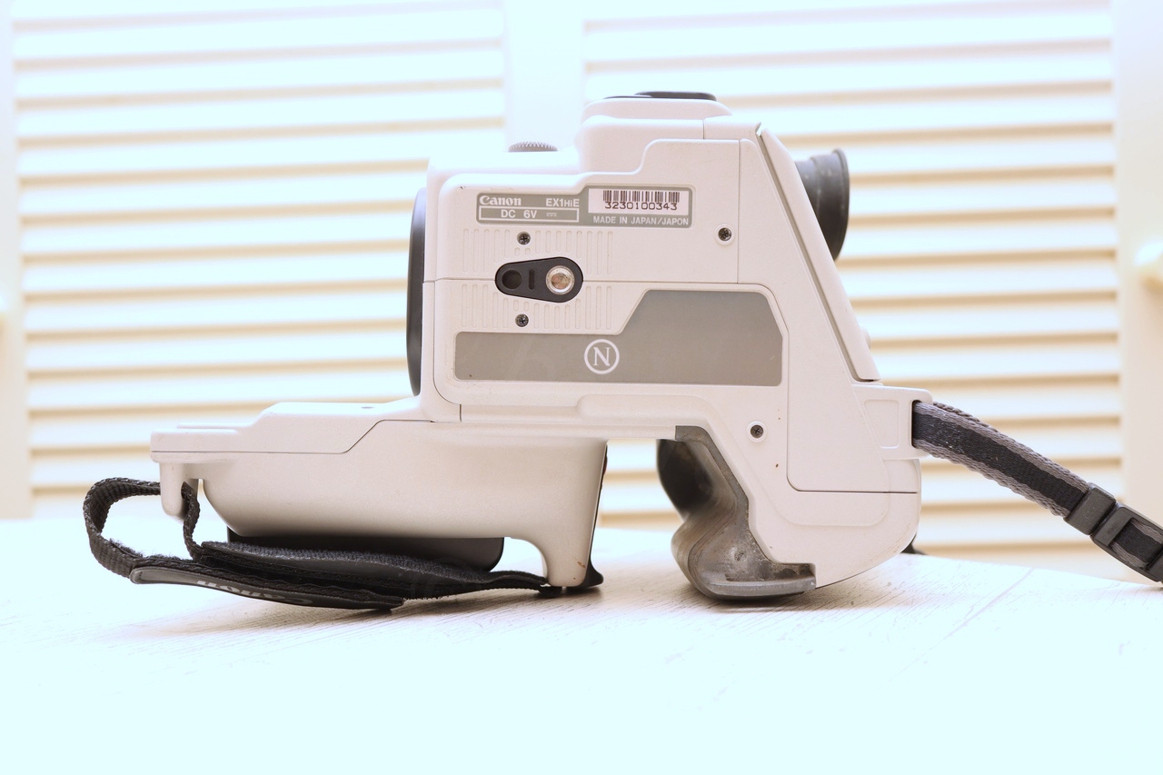
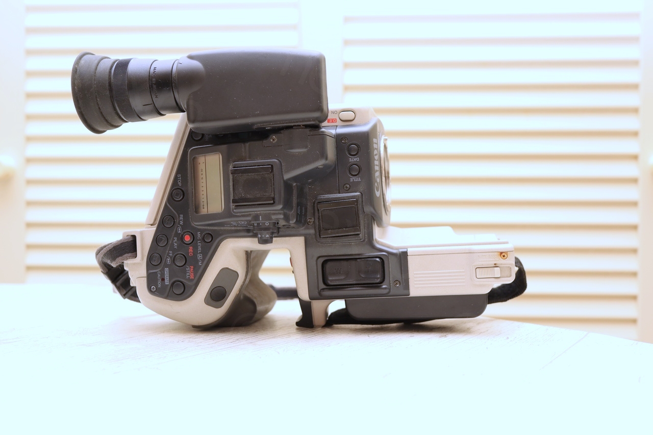
When I have tried to power it with external power, only some little text appeared on the LCD, but no other reactions – this gave me a sinking feeling that this mini CRT will require some work too, signs were not good.
I proceeded with opening up the camera to get access to the EVF unit:


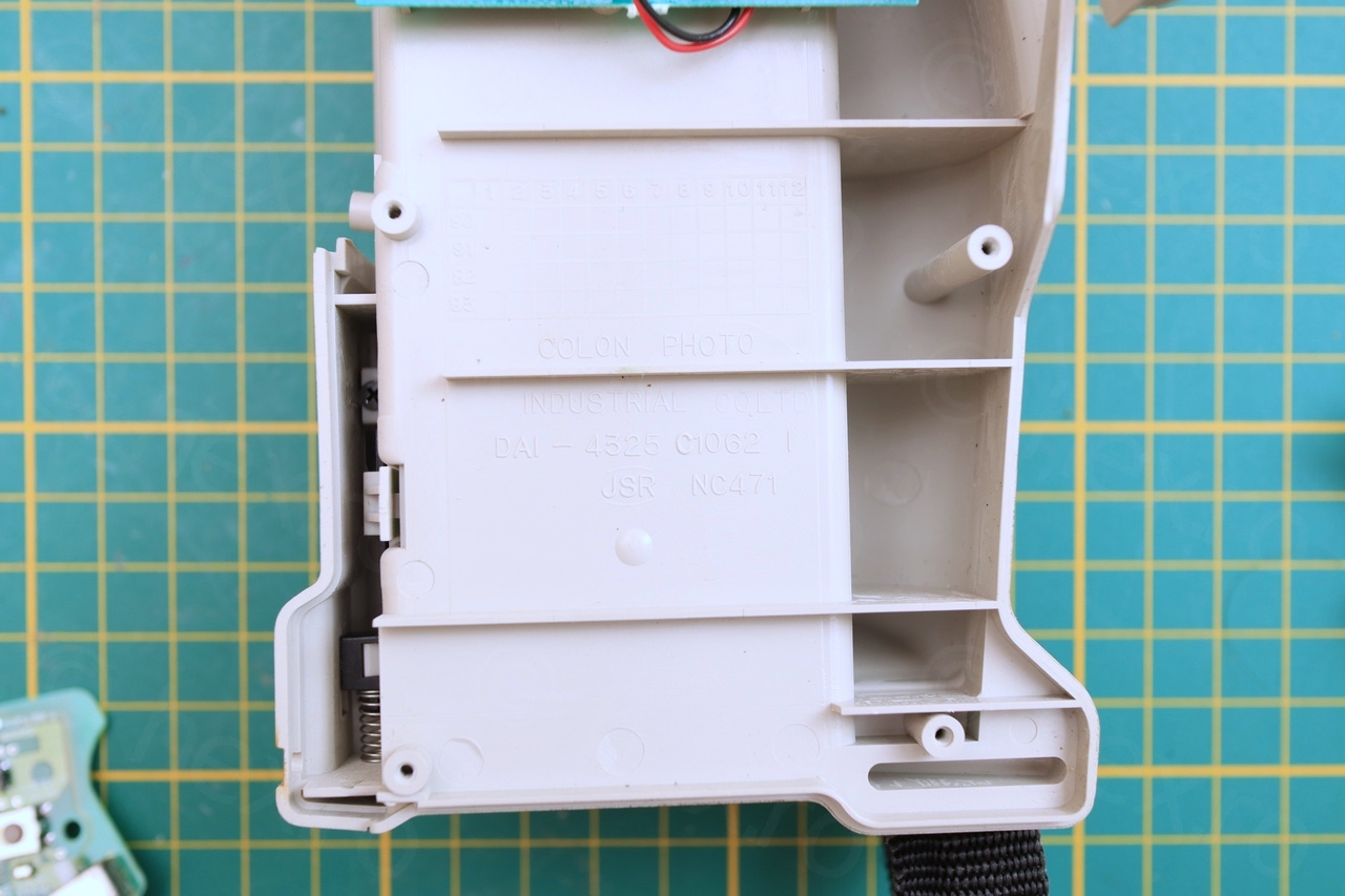
Camera was easy to get into and carefully made. There weren’t many parts I could salvage from it, but I kept the potentiometers and the on/off sliding buttons.
EVF Unit
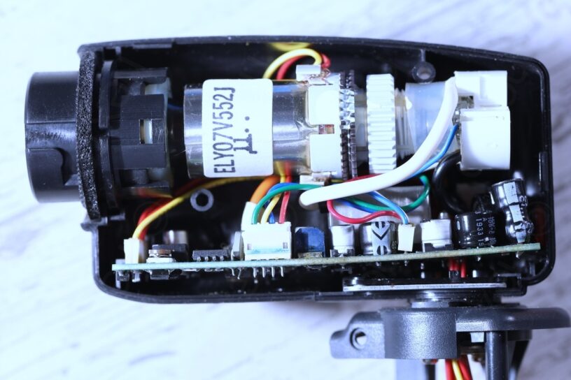
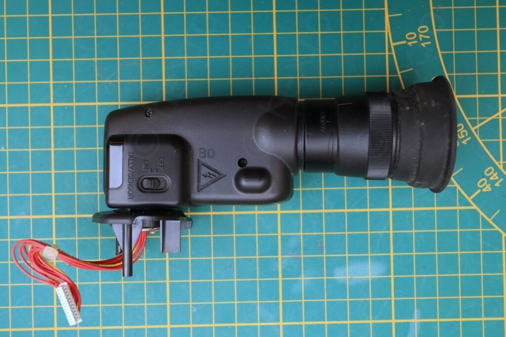
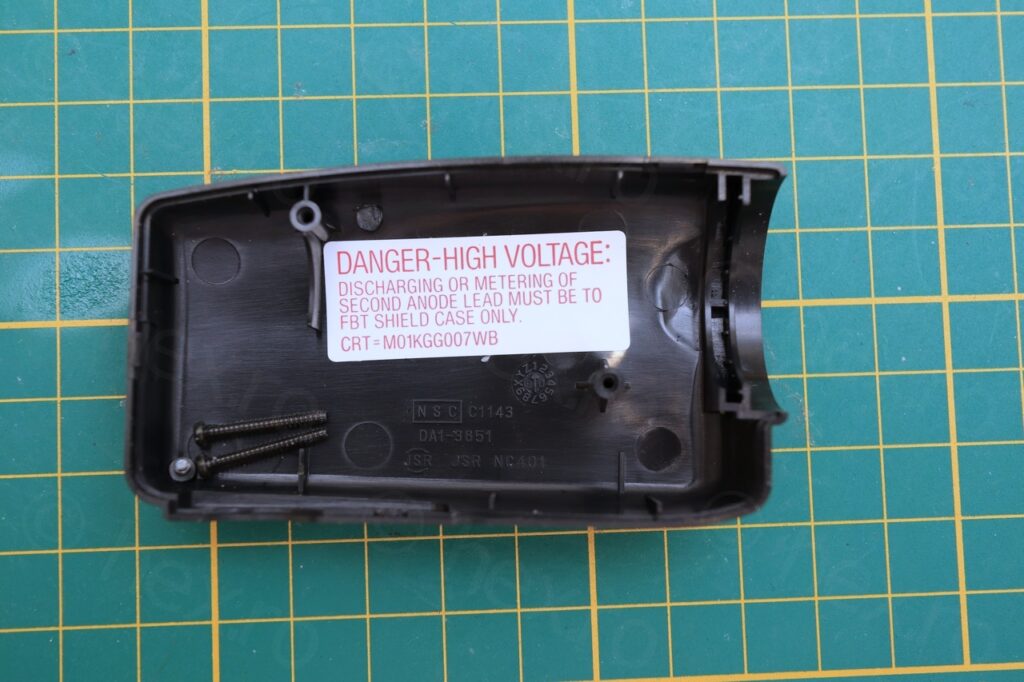
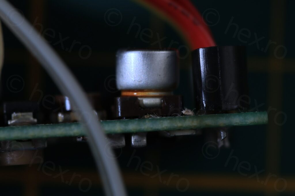
Opening up the EVF unit was also very easy with no hidden catches. I found an AN2514S driver IC and the ELY07V552J CRT.
Measuring FBT voltages 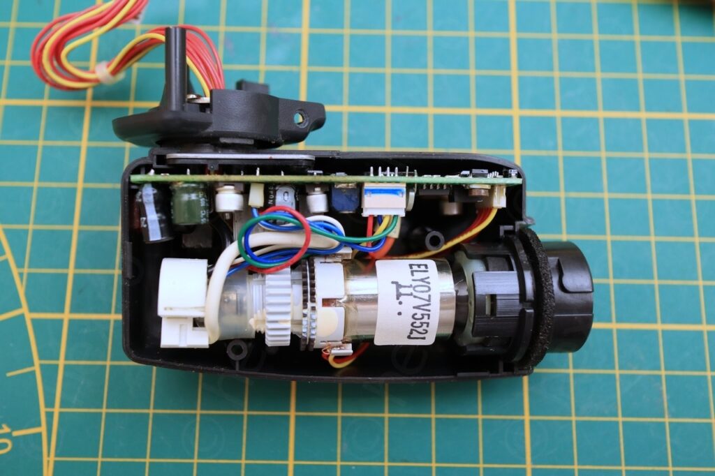
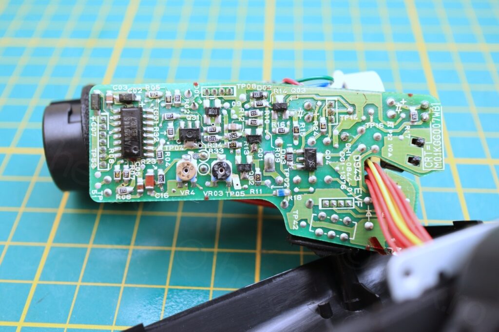
D943 EVF
Both on the case of EVF as well as on the board is mentioned that is CRT = M01KGG007WB but the marking on the CRT itself is ELY07V552J ? A small mystery.
Probing for the VCC and GND was fruitless, I did find the ground (FBT case is connected to GND) but it was difficult to search for the VCC. I thought I located it, but still the little unit would not come on. However, having done another Canon in the past, they do have a voltage regulator on board and an ‘turn on’ signal that is independent of the VCC/GND. However, I was not able to source any schematics on the EX1 model.
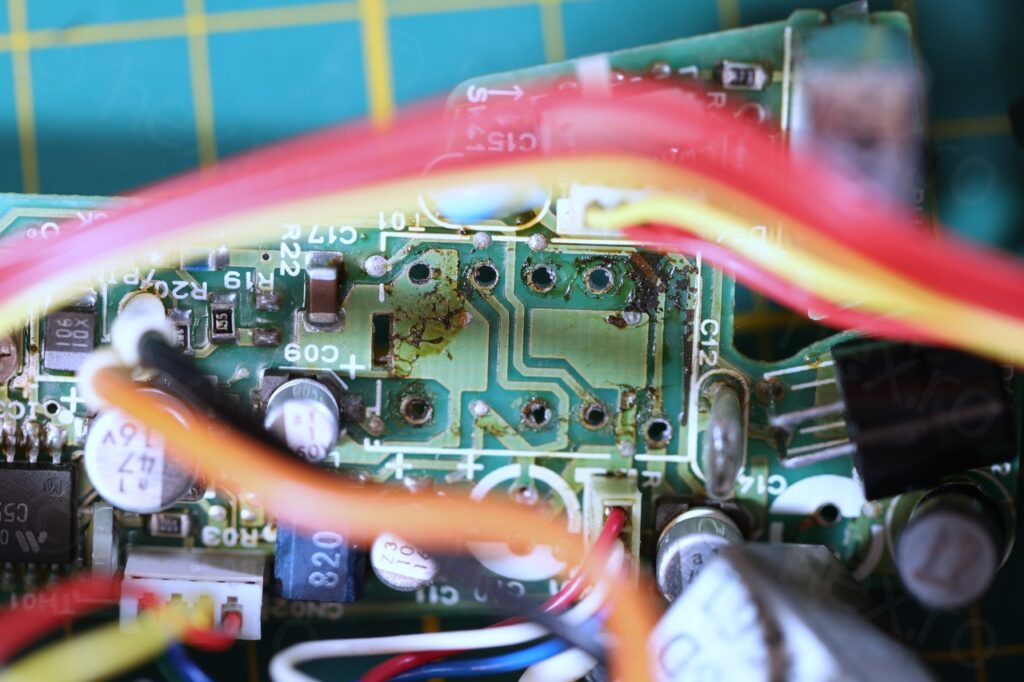
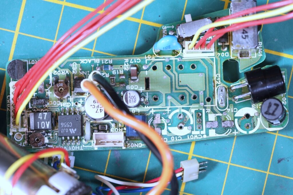
However, on close inspection, it was obvious that something was already wrong, there was a lot of brown deposits on the driver board. Crème Caramel board:
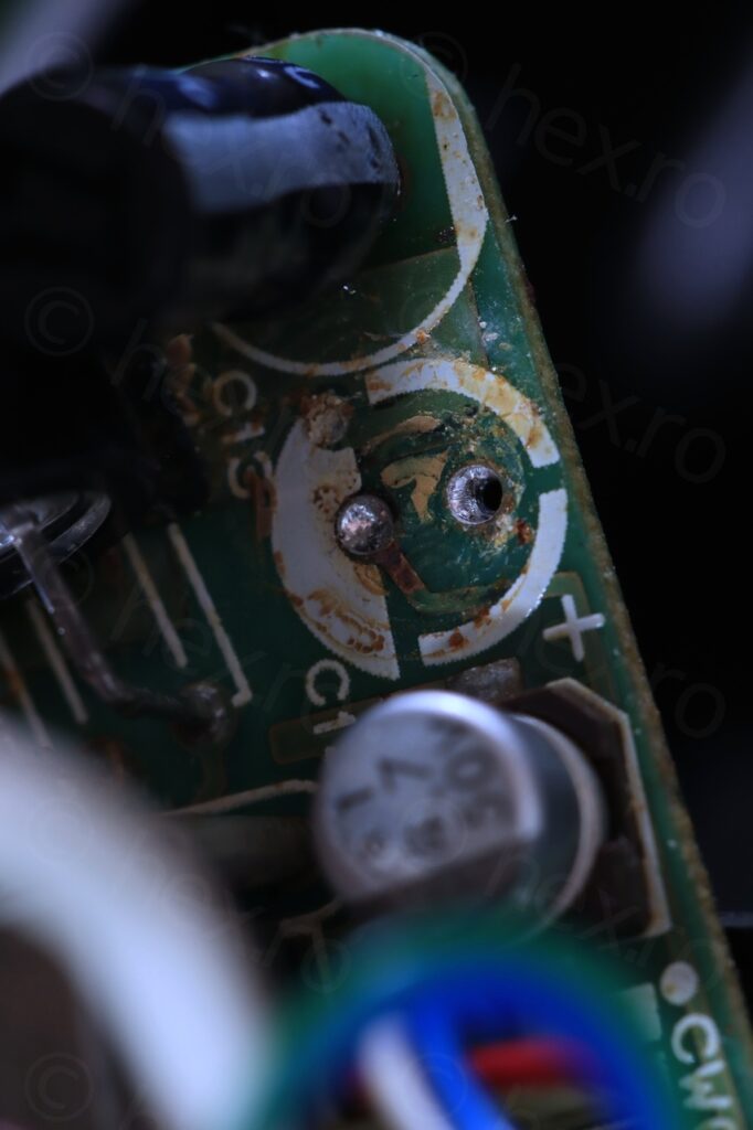
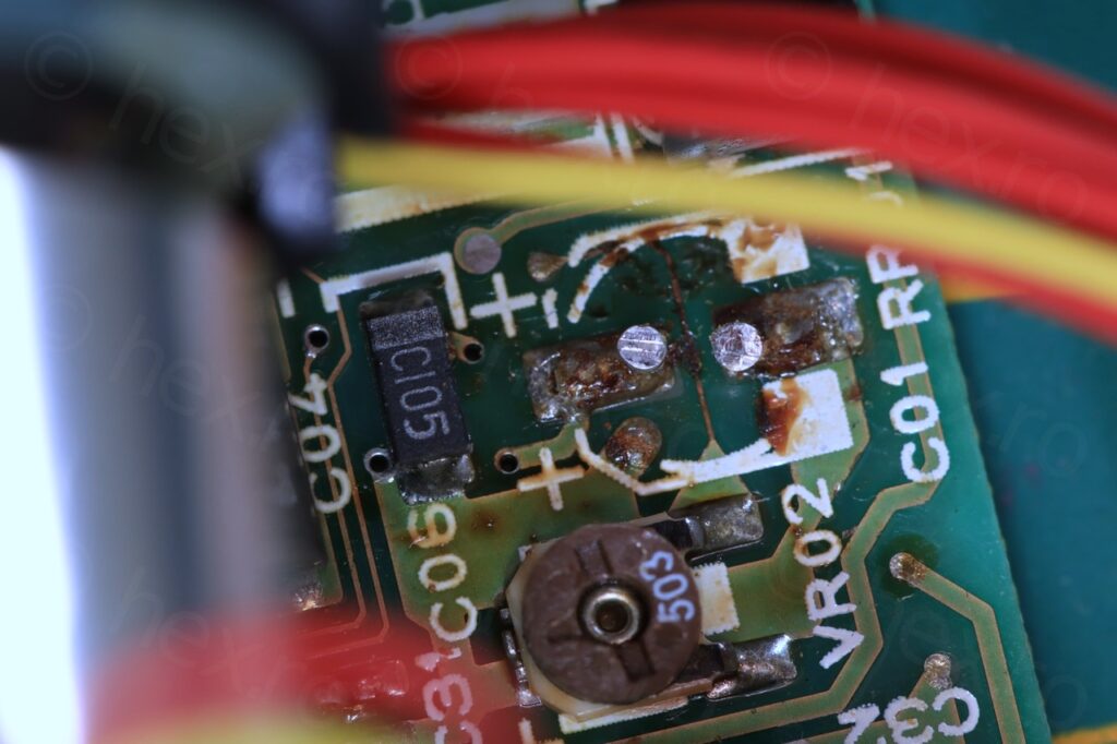
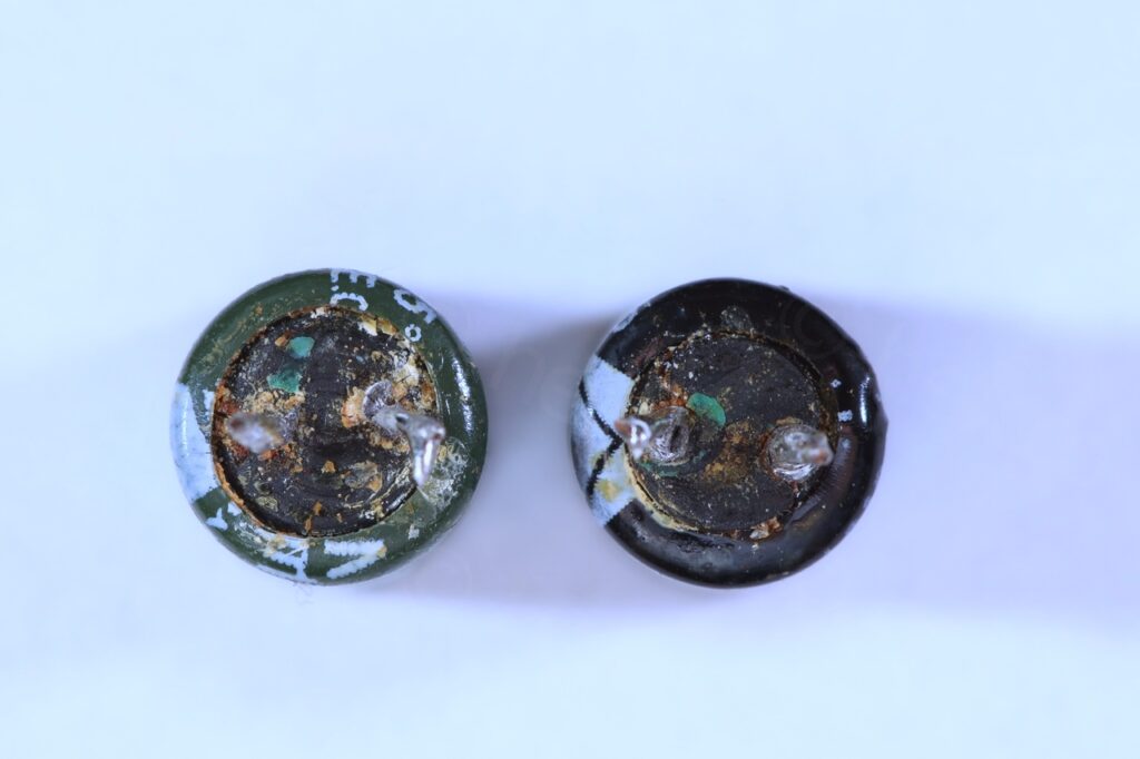
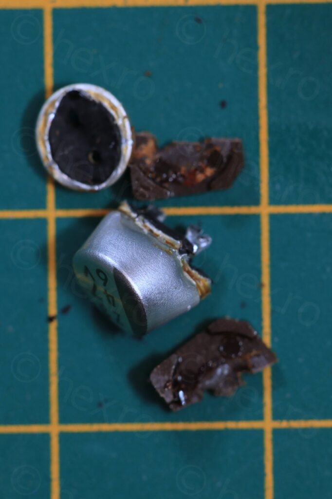
Leaked electrolytics
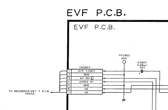
While searching left and right for the Canon EX1 schematics, I was able to find the Canon EX2 schematic and wondered what if they reused some of the components – maybe for example the EVF unit ?! It seems they did!
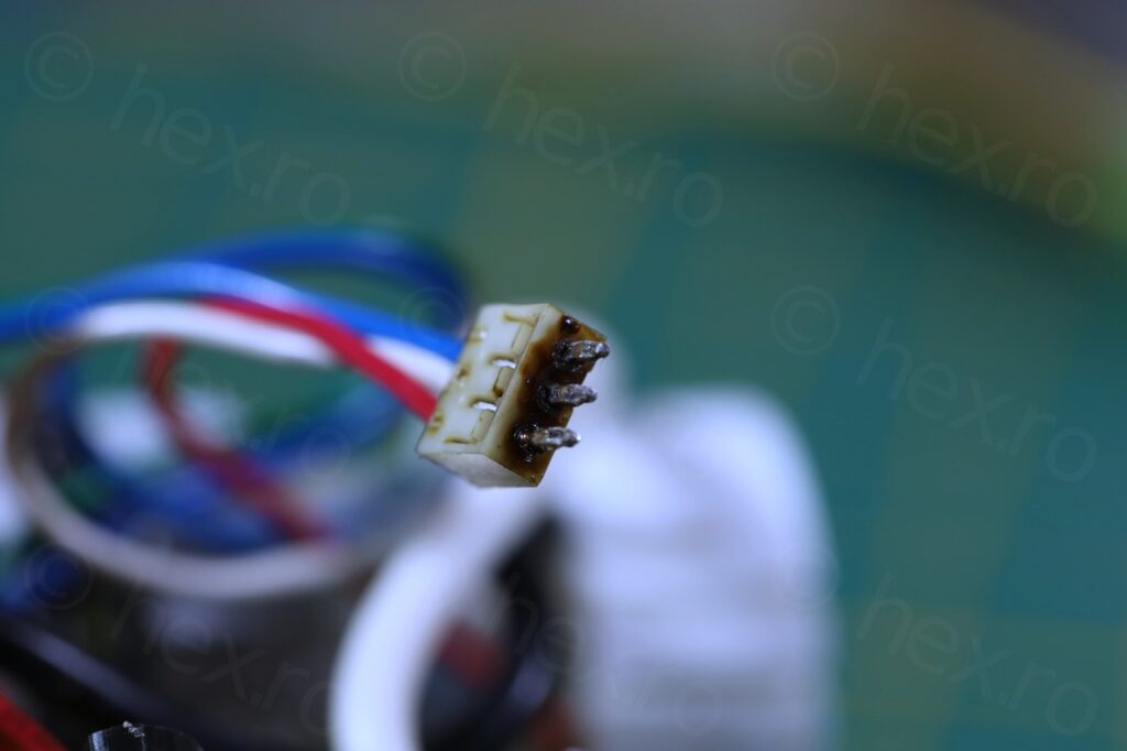
There is indeed another pin (pin 3 on the connector) which is active low and is called ‘AV ON’. I hooked it to ground, but still no life out of the board (not even the high voltage pitch of the FBT):
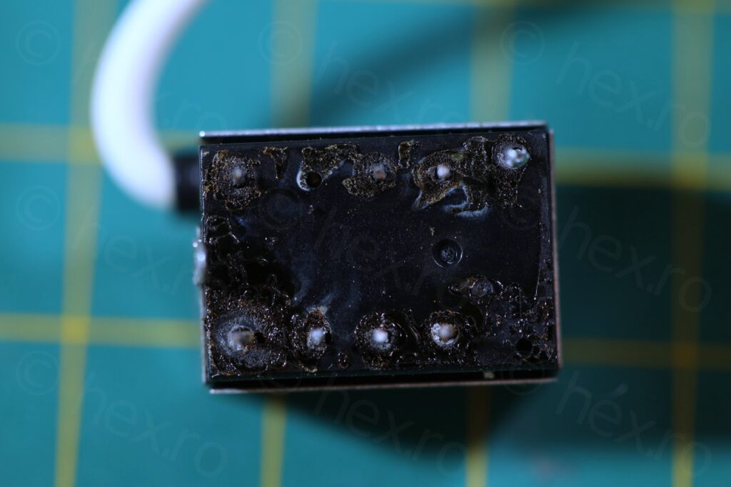
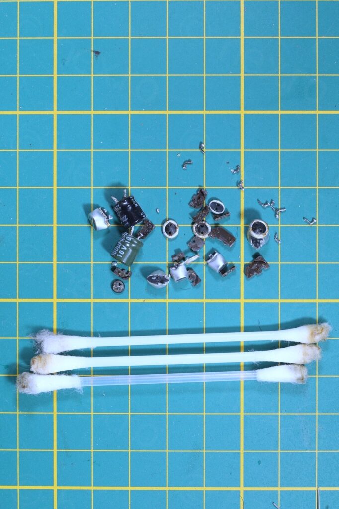
I decided to cleanup the board and swap all the capacitors. Unfortunately, they were so crammed together that I had to also desolder the Fly Back Transformer and another plug, just to get some more room to work with. And .. results were not good, everything was brown and crusty, took a lot of alcohol to clean everything up:
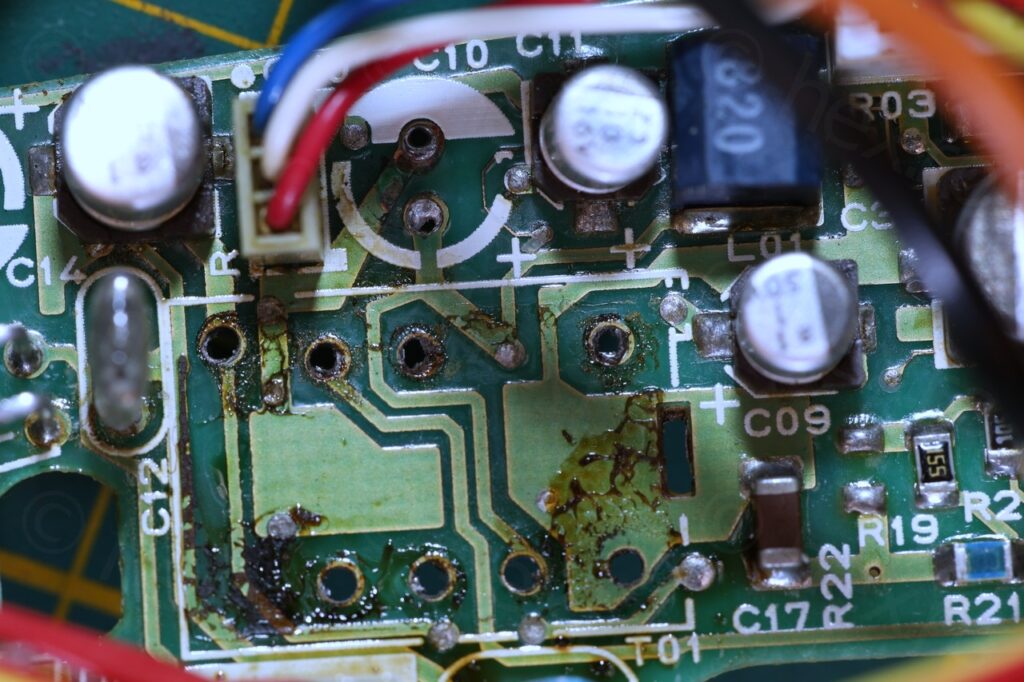
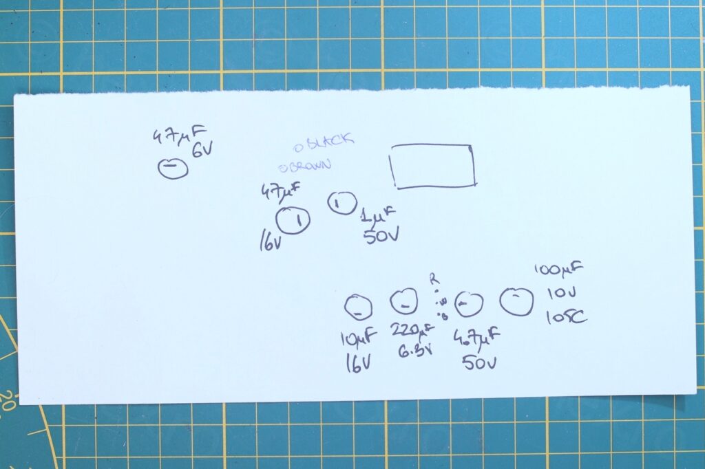
I had to clean everything up and I did my best. I also made a map of the electrolytics as I didn’t have them all and I needed to wait for parts.
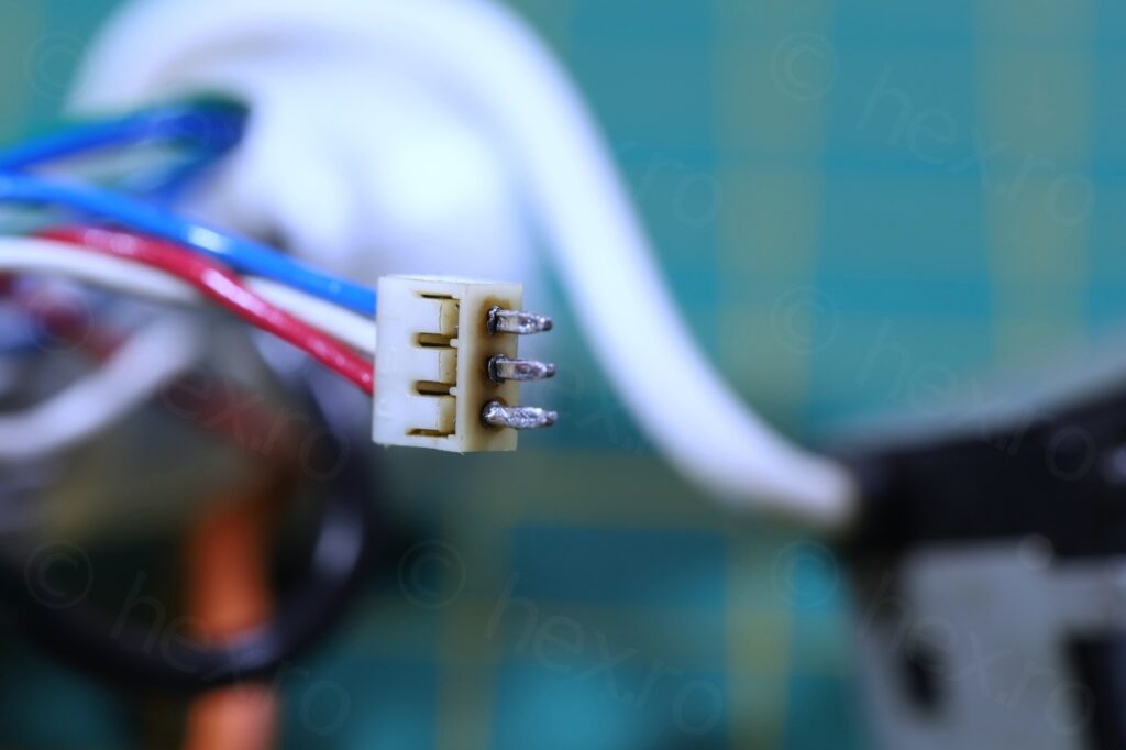
I was still hoping maybe there is a chance with the board but alas. After swapping out all capacitors and soldering the FBT and the little cable back, still no luck.
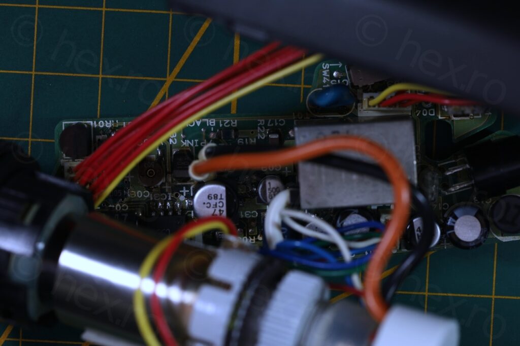
Board re-capped.
The driver IC gets warm (not hot) and I don’t remember others becoming warm so quickly. Also, no sound from the FBT.
Since I have few more cameras to go through, this EVF will go to storage marked as ‘NOT WORKING’. While the EX2 schematics does show the voltages, I need a microscope to make it easier to follow everything around, and I don’t have that. Nor I have parts the IC to swap out in case I decide it is broken .. so for now, stored as ‘NOT WORKING’.
David Welsh
My CanoVision EX1Hi refused to switch on after spending several years locked away in a cupboard. Changed the Li Ion battery and low and behold it switched on for about 20 secs, time enough for me to insert a tape and then it stopped. Have been unable to get any joy even using the external mains power supply. Re-chargeable battery is fine. So the tape is stuck in the camera until I can get it to work again.
Plan on opening and looking to change a range of caps; so any information concerning the schematic or insides of the camera would be very welcome or suggestions as to where this info could be found would be most helpful please.
Tom Ahola
I’m servicing my EX1 again. Previously years ago I replaced many leaky caps, but only the bad ones as tested in-place. Now I plan to replace all caps. The EVF works great again. It took a while to get it working. One trace had corroded from the electrolyte. It was under a capacitor I replaced earlier. The EVF is challenging due to high impedances. It took a long time to figure out that there was a leakage current due to ~1 Mohm between gate1 and cathode, caused by some electrolyte residue in the white board “connetor” for the three cathode, gate, filament wires. This caused the image to be overly bright even in the darkest trim position.
Now my problem is that on audio-1 board there is a connection between a via and a pad that looks corroded but I’m not sure if there is supposed to be a connection there or not. Unfortunately the EX2 service manual does not have a schematic of the audio board!
viulian
Wow, that requires a lot of dedication 🙂 congratulations! I can’t help with the audio part unfortunately, hopefully you can get it going!