


Introduction
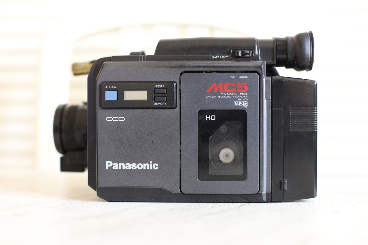
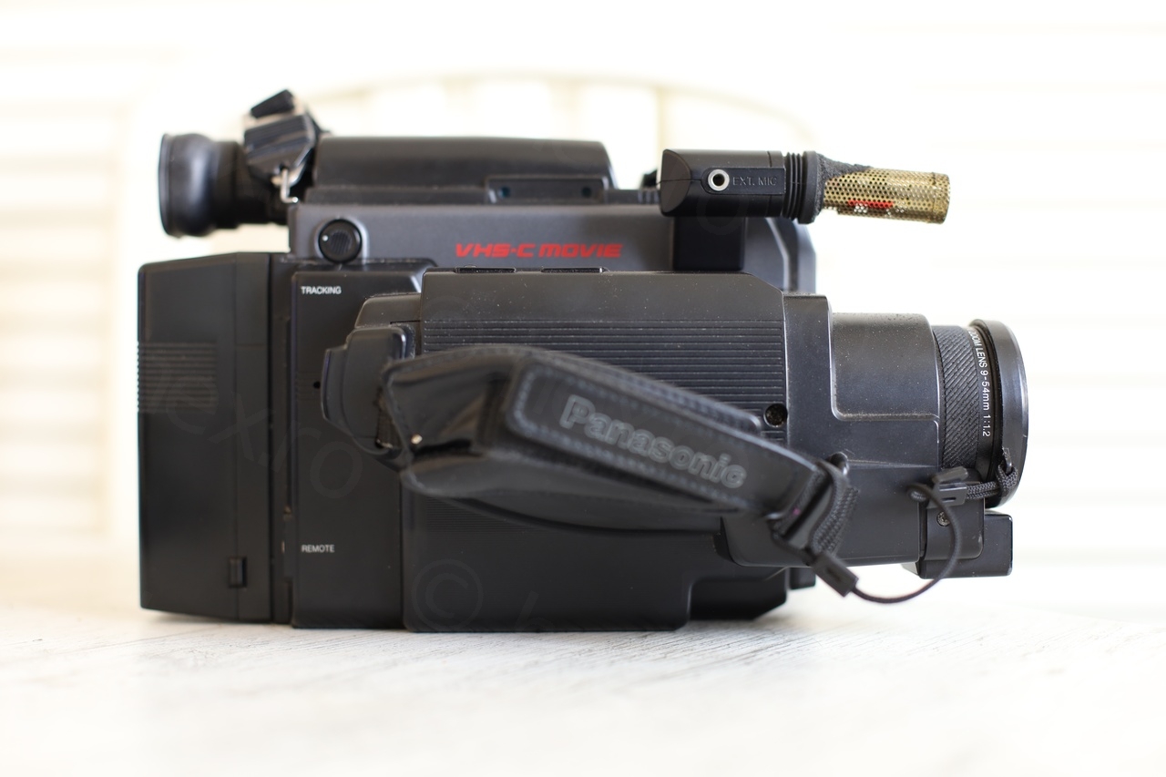
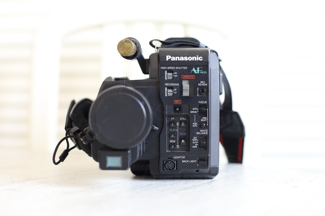
I found this mini CRT inside a Panasonic NV-MC5E camera (Panasonic MC5) bought at a flea market.
Overview
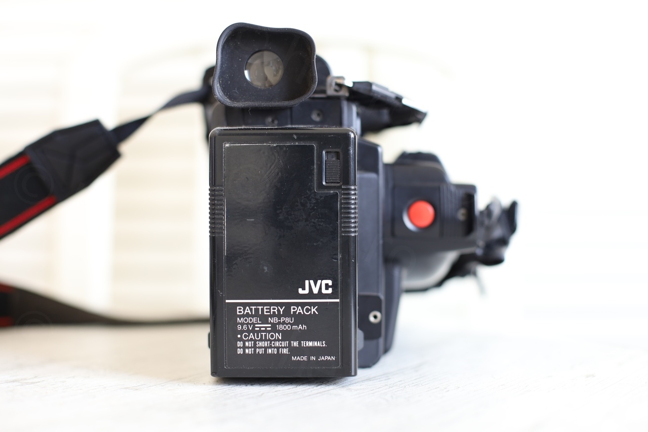
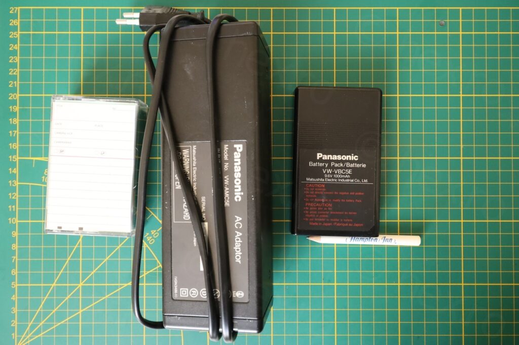
The camera was sold in a bag containing an additional battery, the original charger, as well as the original invoice (either the original or a copy ?). According to it, owner payed 82800 Belgian Francs in 1987 (which is also the year the camera was manufactured, as I later found stamped inside the plastic case).
Camera looked in very nice condition, except the microphone wind breaker which was decomposed.
The contents of the bag were the tape inside the camera, the original charger, another smaller battery and a Hampton Inn crayon. The crayon got me pondering that back in the days, they were giving crayons stamped with the company name, nowadays there are stamped USB sticks. I wonder what will be in the future …
Back in the past, I was curious to have a look inside the power brick. I was surprised to see the insulators around what looks to be some capacitors:


Initial tests
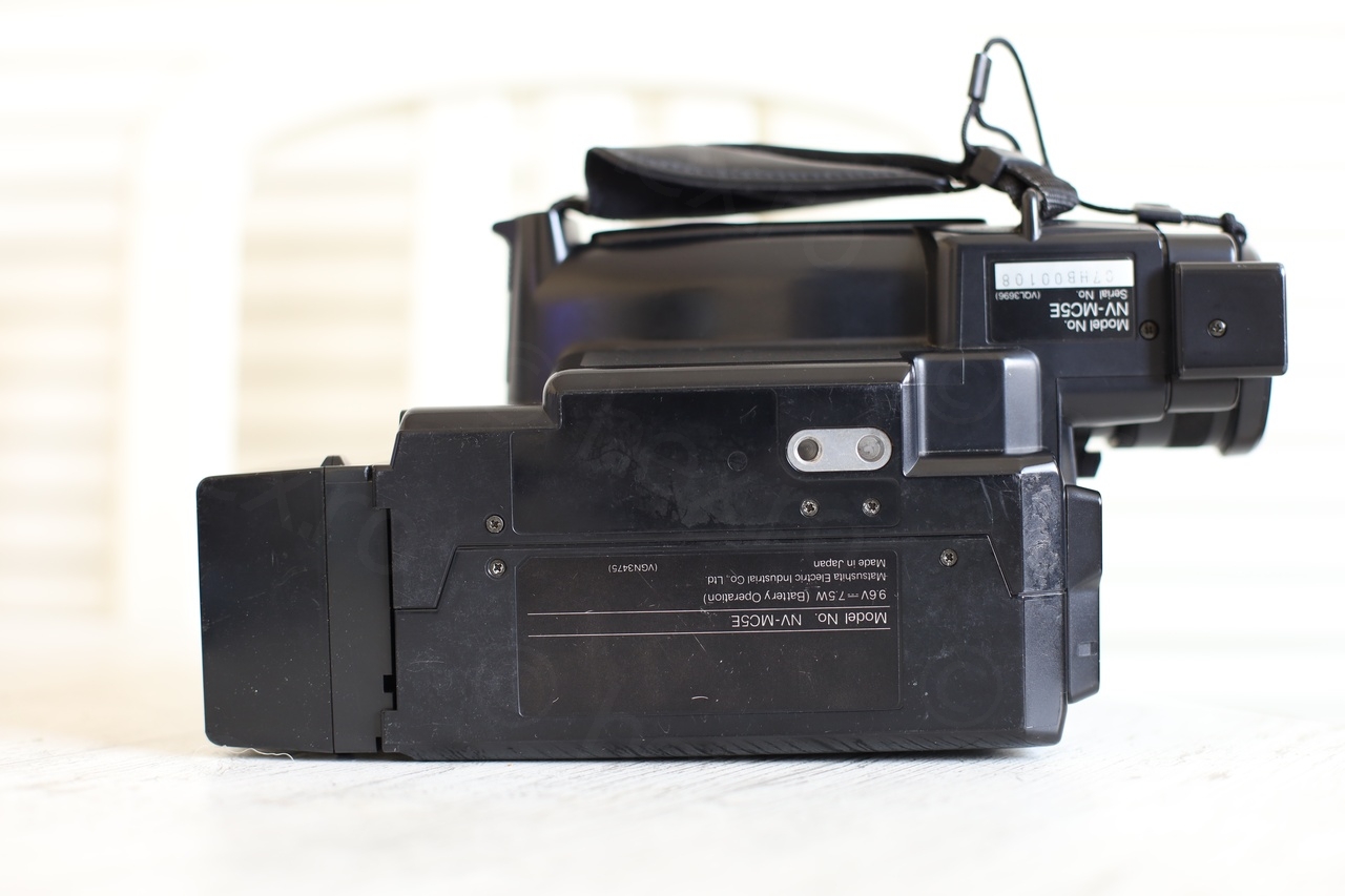
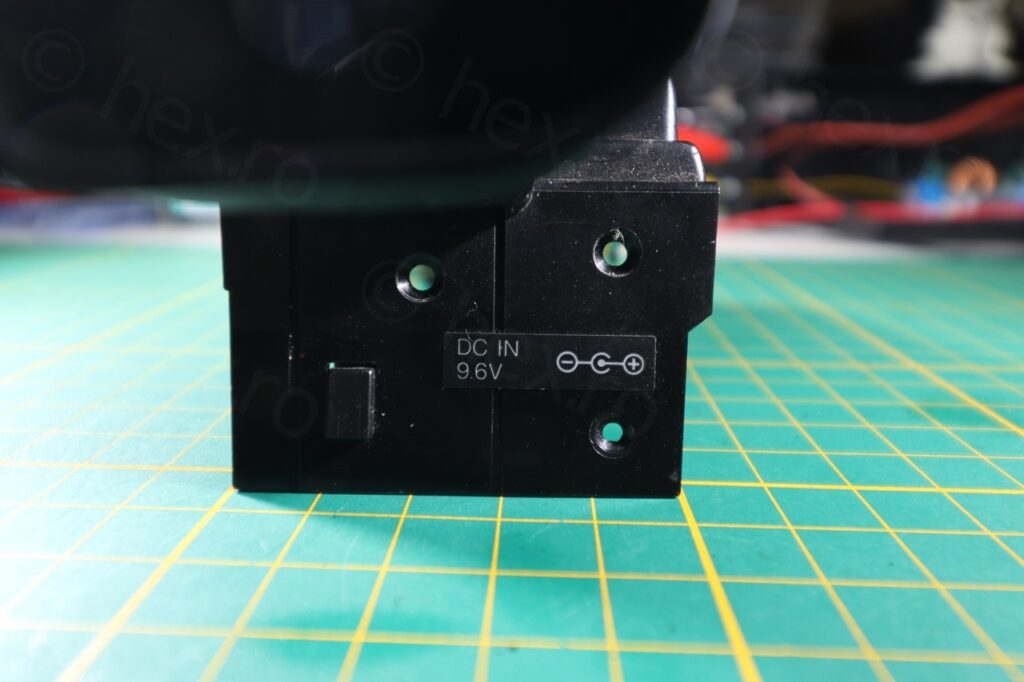
Decided to try to power on the camera, at least to see if the Electronic View Finder is working and also, to try to salvage the tape inside (using the Eject button). Indicators on the back of the camera suggest a 9.6V battery, but usually, the battery has a higher voltage in use. I tried initially with exactly 9.6V but the camera turned off. I decided to up the voltage to 11V and surprise, camera started!
Just idling, camera was drawing 0.5A @ 11V.
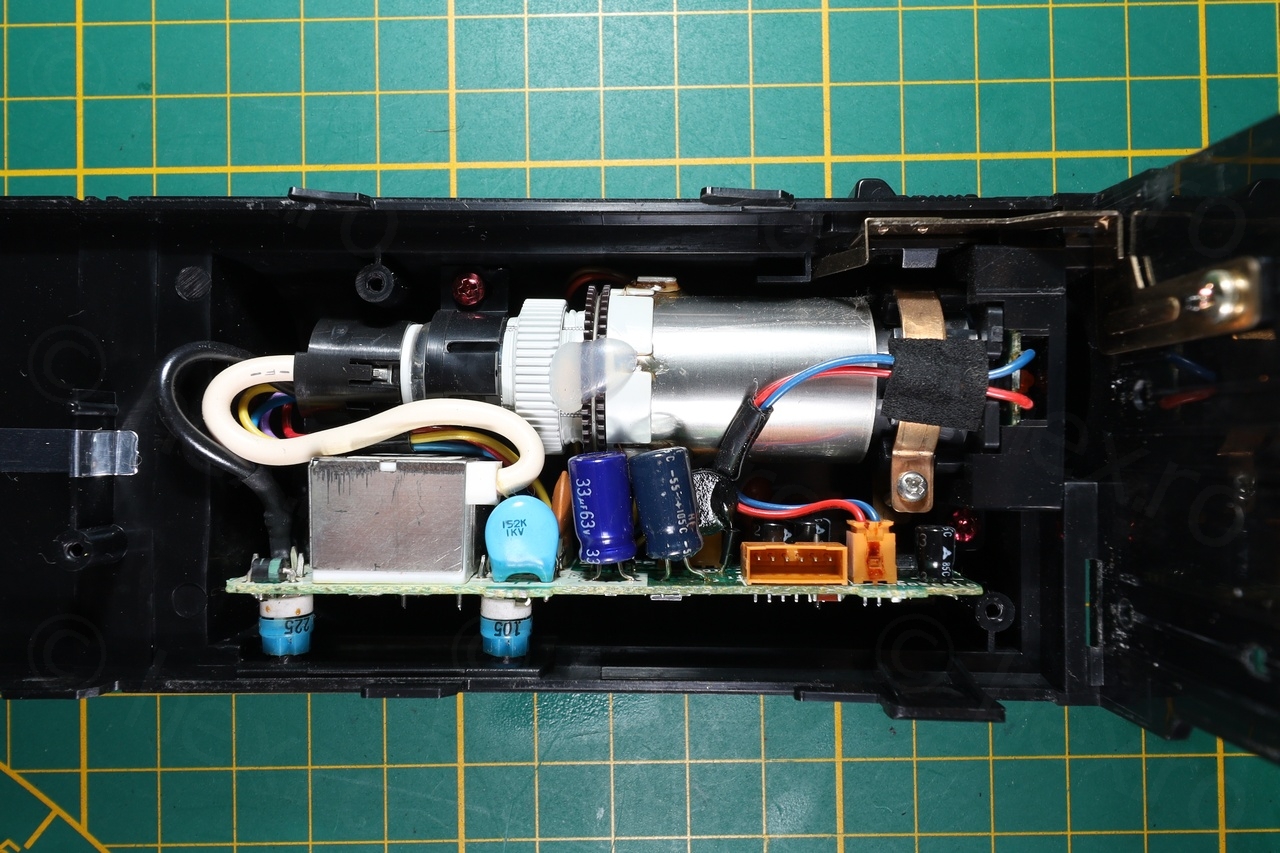
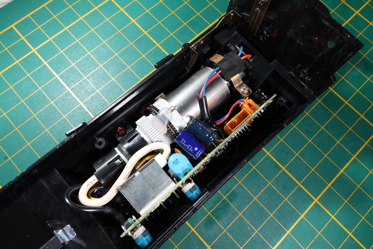
Opening up the Panasonic MC5
Opening up was a little more tedious than I anticipated. There were many screws that I took off, and I was expecting the camera body to just come apart, it took a while until I realized that the top side containing the EVF unit has to be slid towards the back of the camera.
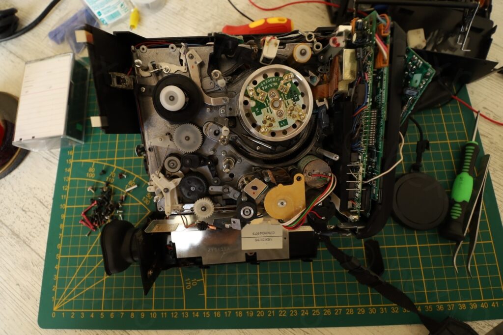
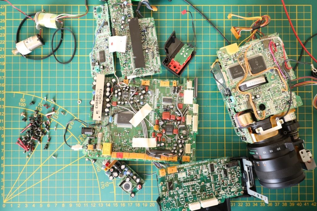
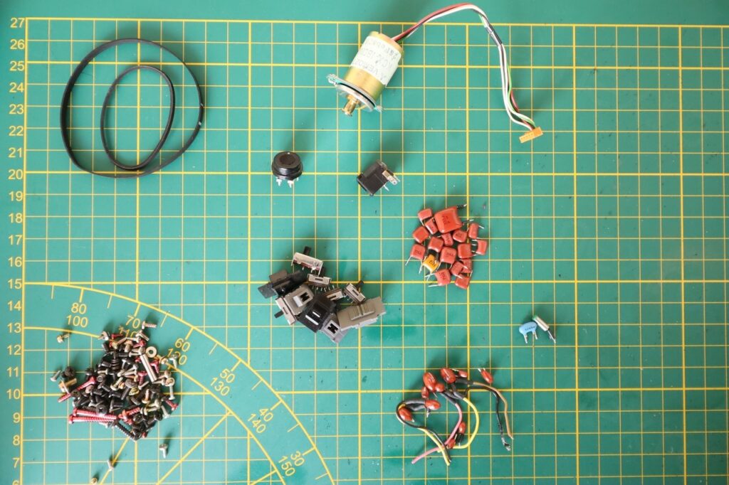
Many small boards inside and a lot of interconnect wires. I was able to salvage many tantalum capacitors, the switches and few more parts. One of the motors seem to have an RPM detector, I kept it.
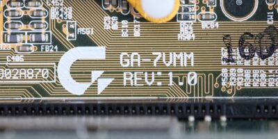
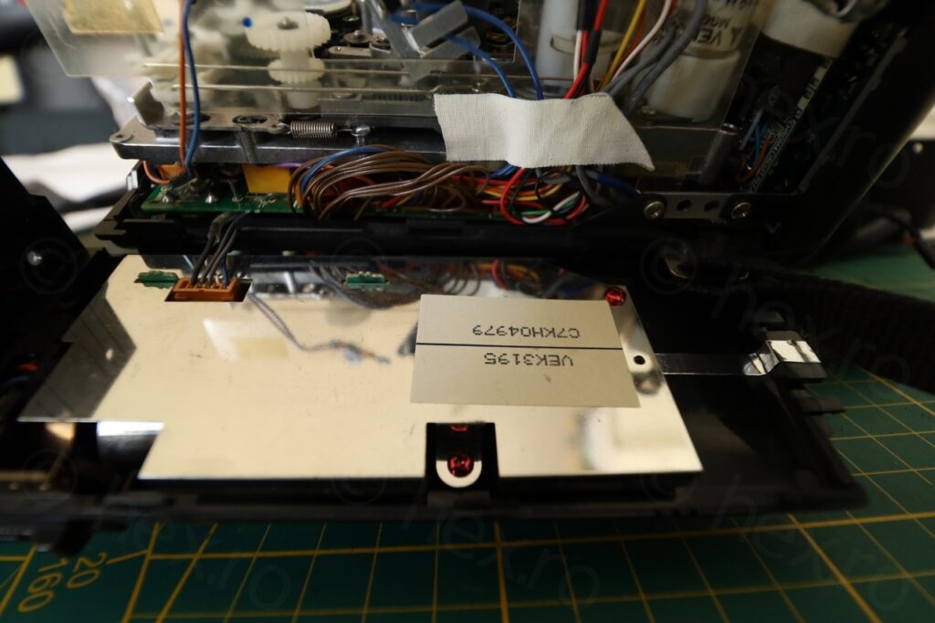
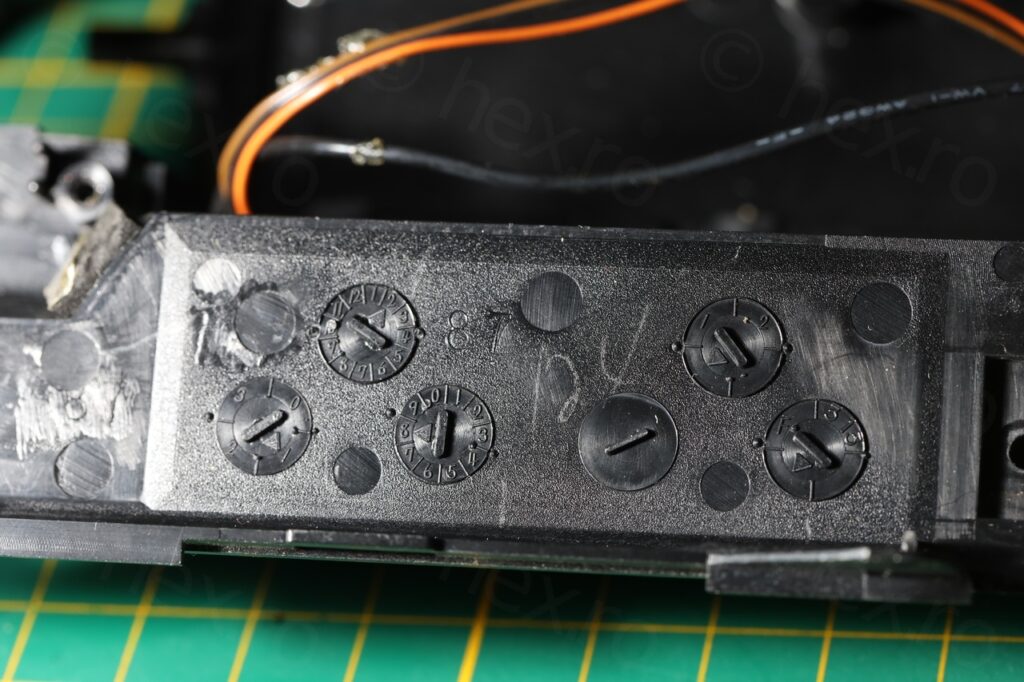
On the insides of the camera stood the manufacturing date:
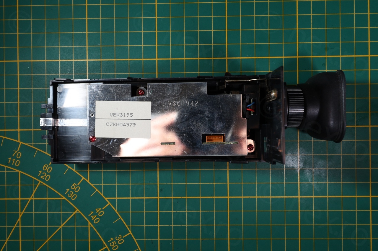
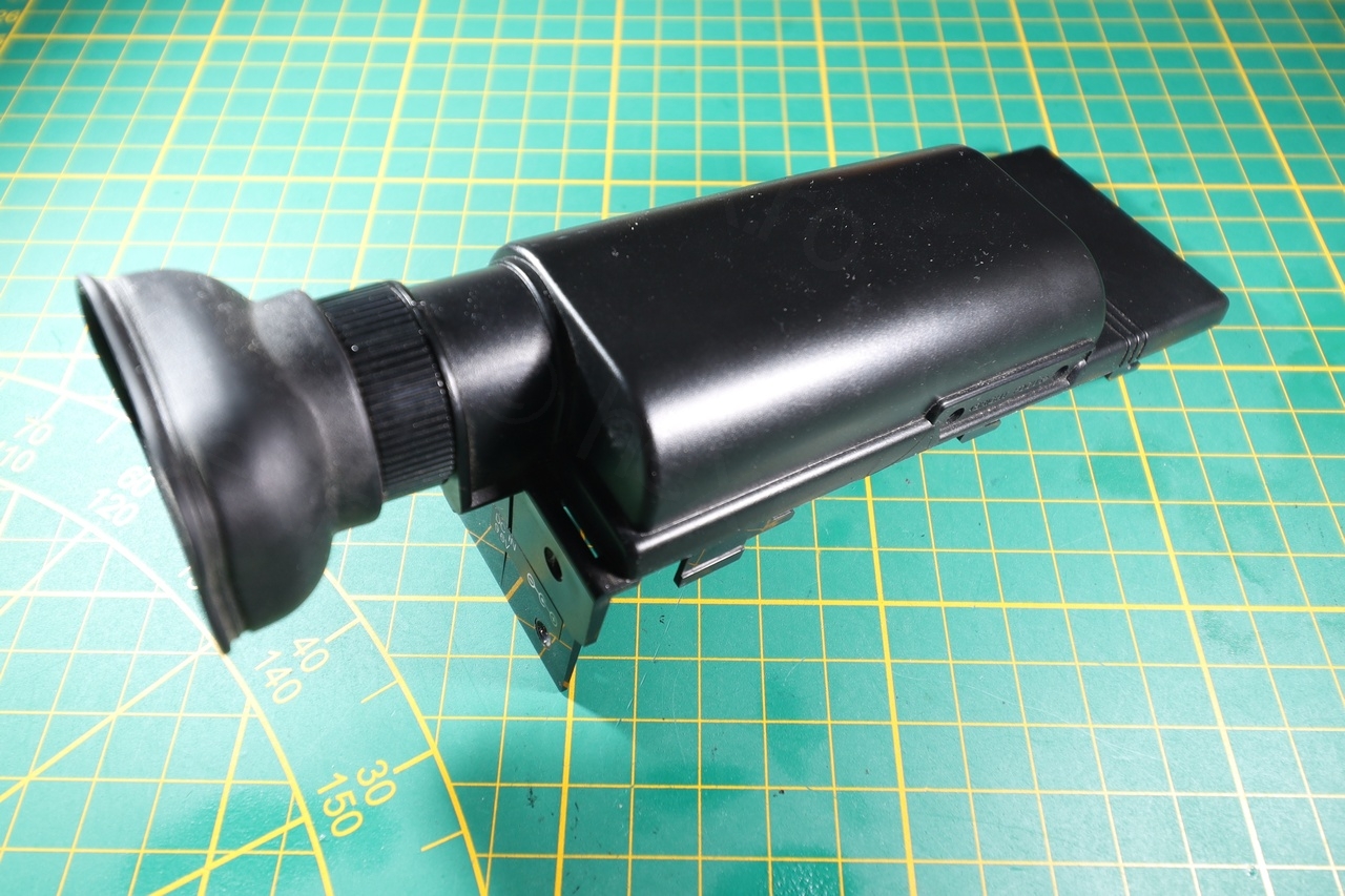
Electronic View Finder
The EVF unit is housed in the top cover of the camera:

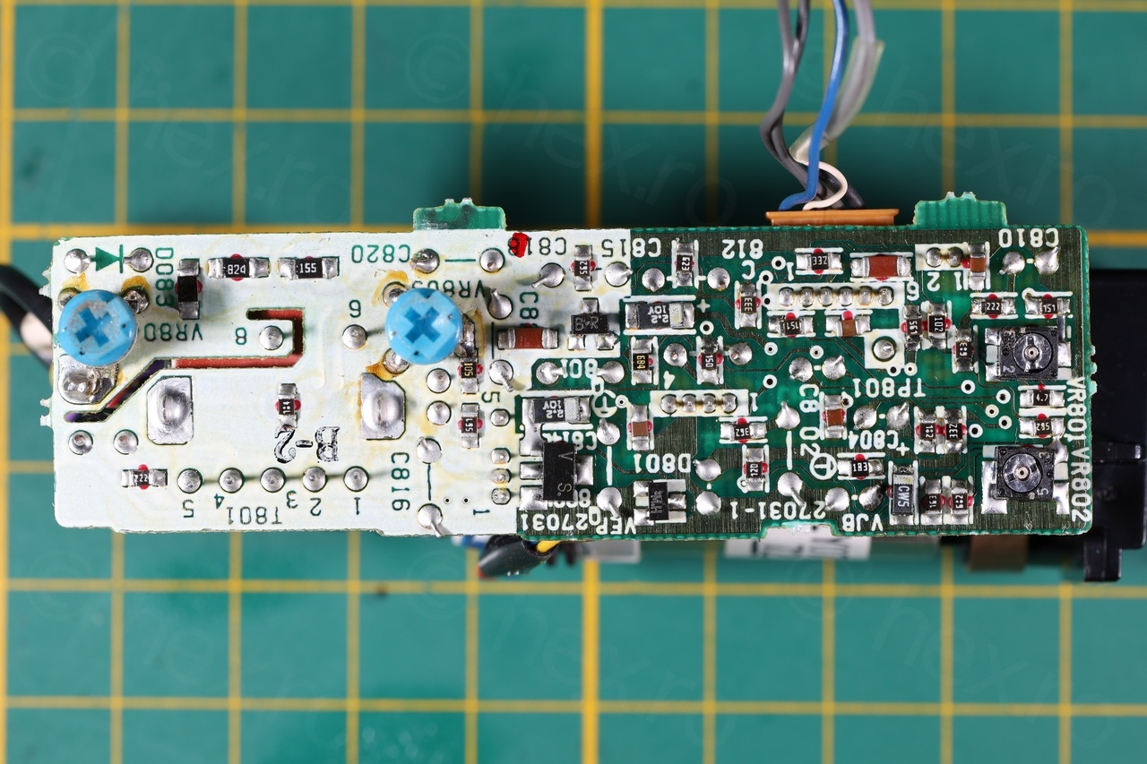
Proceeding inside, I noticed a very clean board – having through-hole electrolytic capacitors. Since EVF working was on the camera – I was a bit more relaxed trying to identify the connection pins.
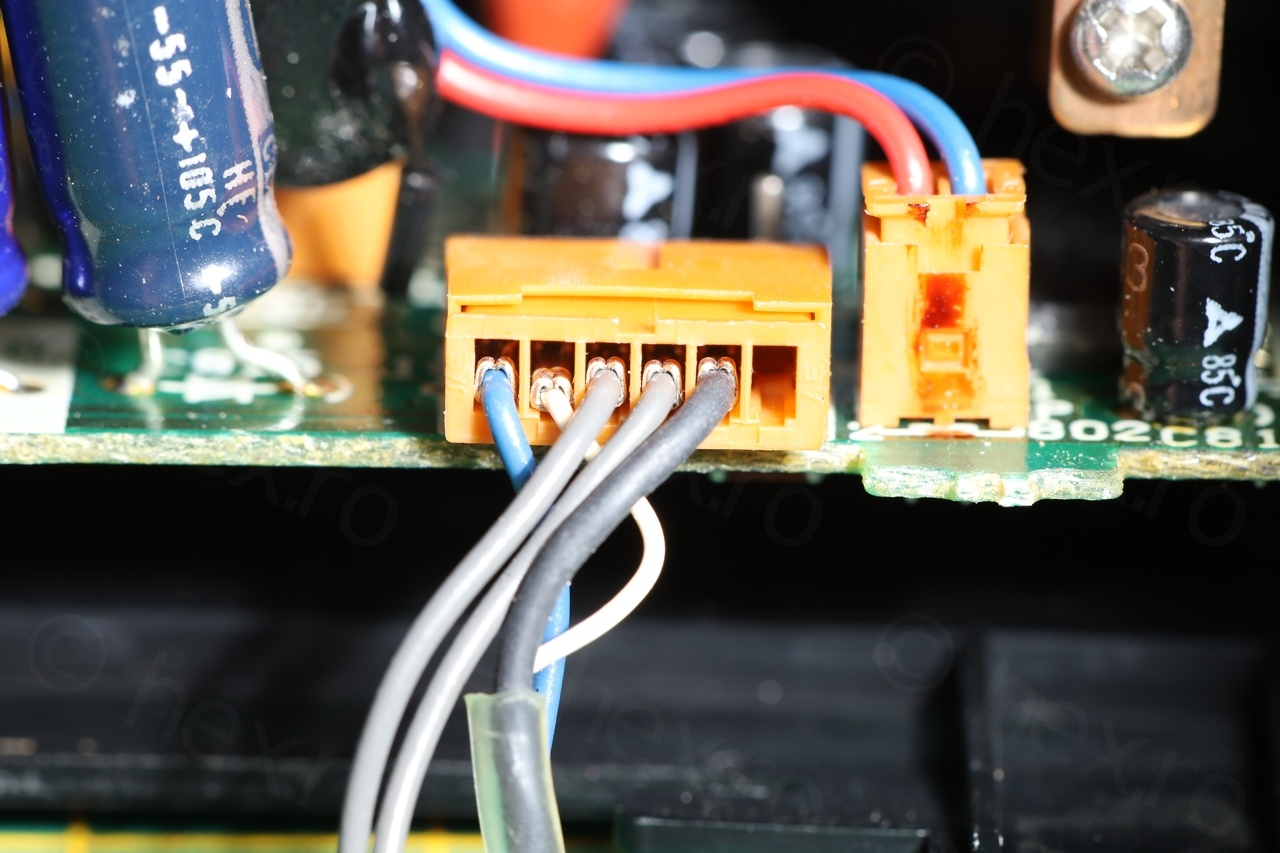
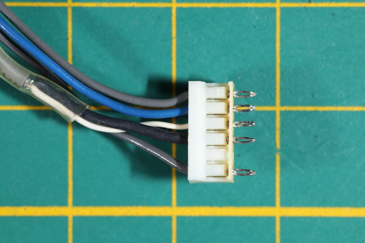
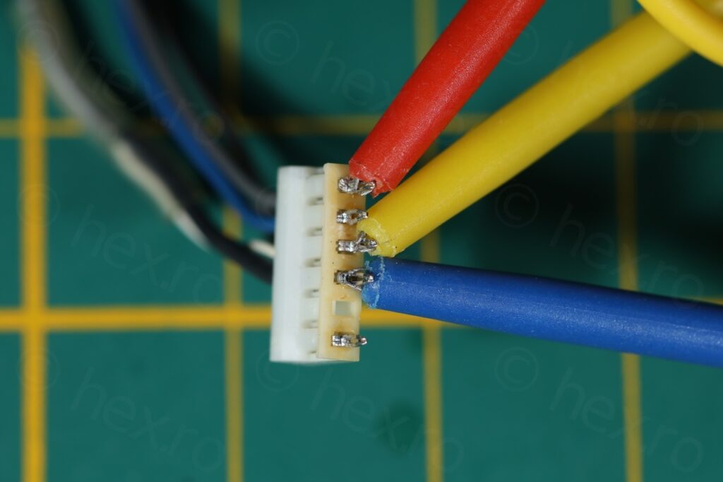
Using the original cable that I desoldered to send signals to the CRT made it much easier to attach signal clamps:
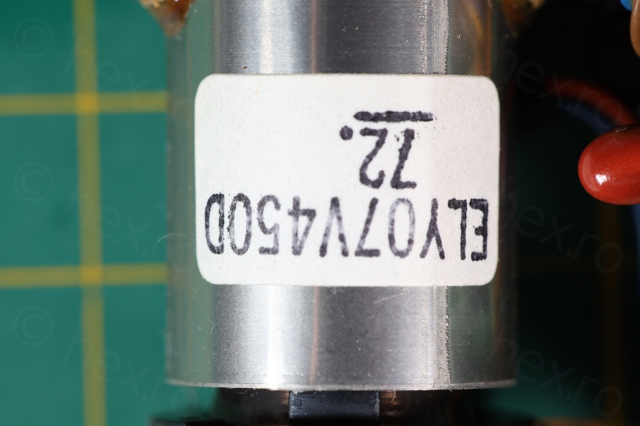
Like all the other boards, the Flyback Transformer has both the VCC and GND connected to it, and GND is connected to the exposed shield. Thus, identifying VCC and GND was easy, and a bit of trial and error revealed the VIDEO IN Signal.
Just under the eyepiece magnifier, the plastic has a sticker calling for 9.6V battery (as that plastic formed the top part of the space where battery was supposed to be attached). I powered the CRT with 5V though – since I could always go to 9.6V, but 9.6V did not sound believable for an EVF:
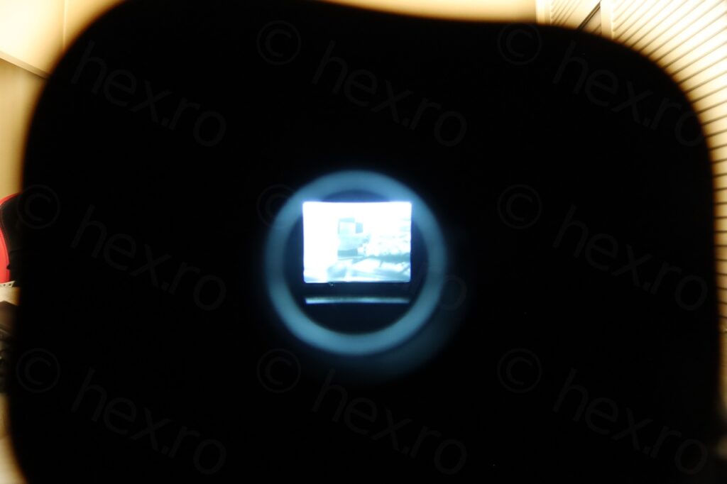
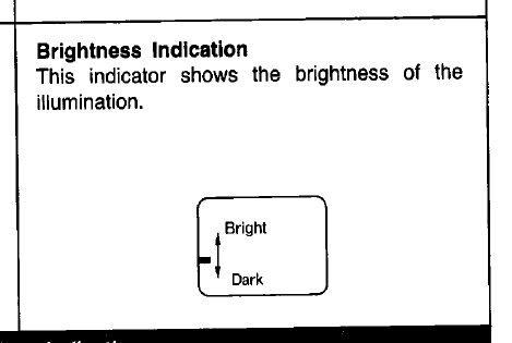
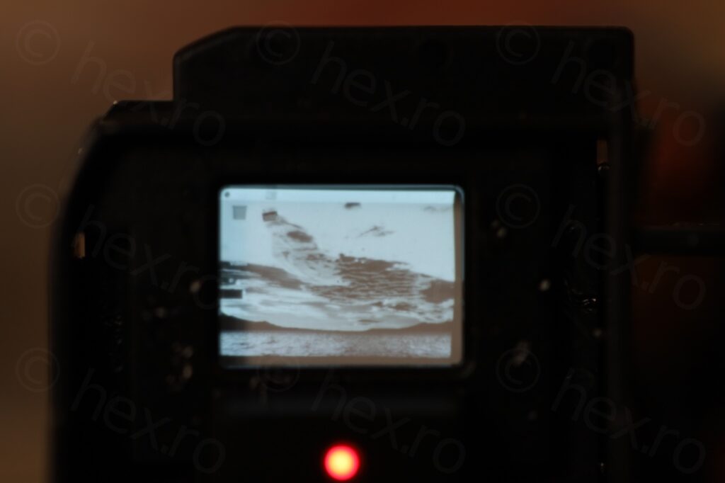
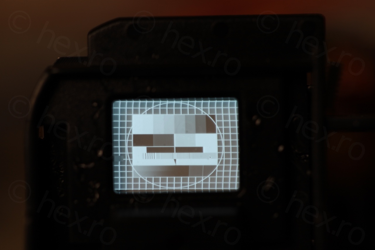
After applying the voltage, the CRT lit up 🙂 however, there was a small annoyance: a white bar visible on the left of the CRT. It looked rather sharp – is it something generated by the board instead or a defect ?
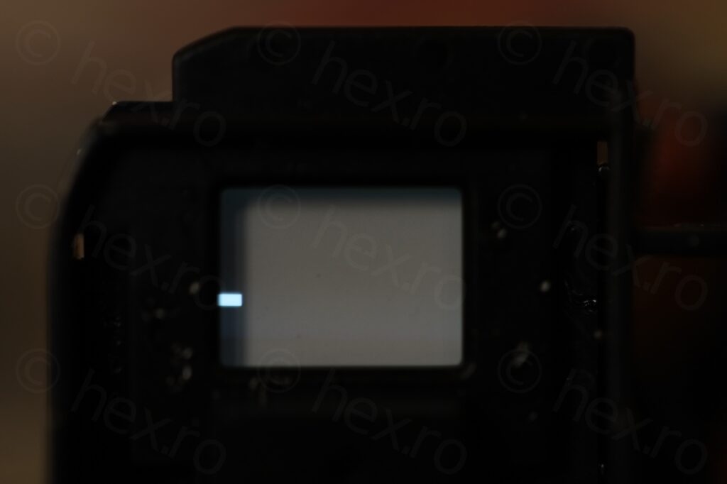
Luckily I was able to find the scanned operation manual, it seems that the bar served as brightness level:
Additional PINs
The isolated one on the bottom is the one controlling the RED light at the bottom of the viewfinder – which manual describes as White Balance Indication Lamp.
I think there is no resistor in series with the LED, as connecting its associated PIN to VCC degrades the image quality a lot (too low voltage and LED is very bright). Probably the resistor was somewhere on the camera’s circuit board ?
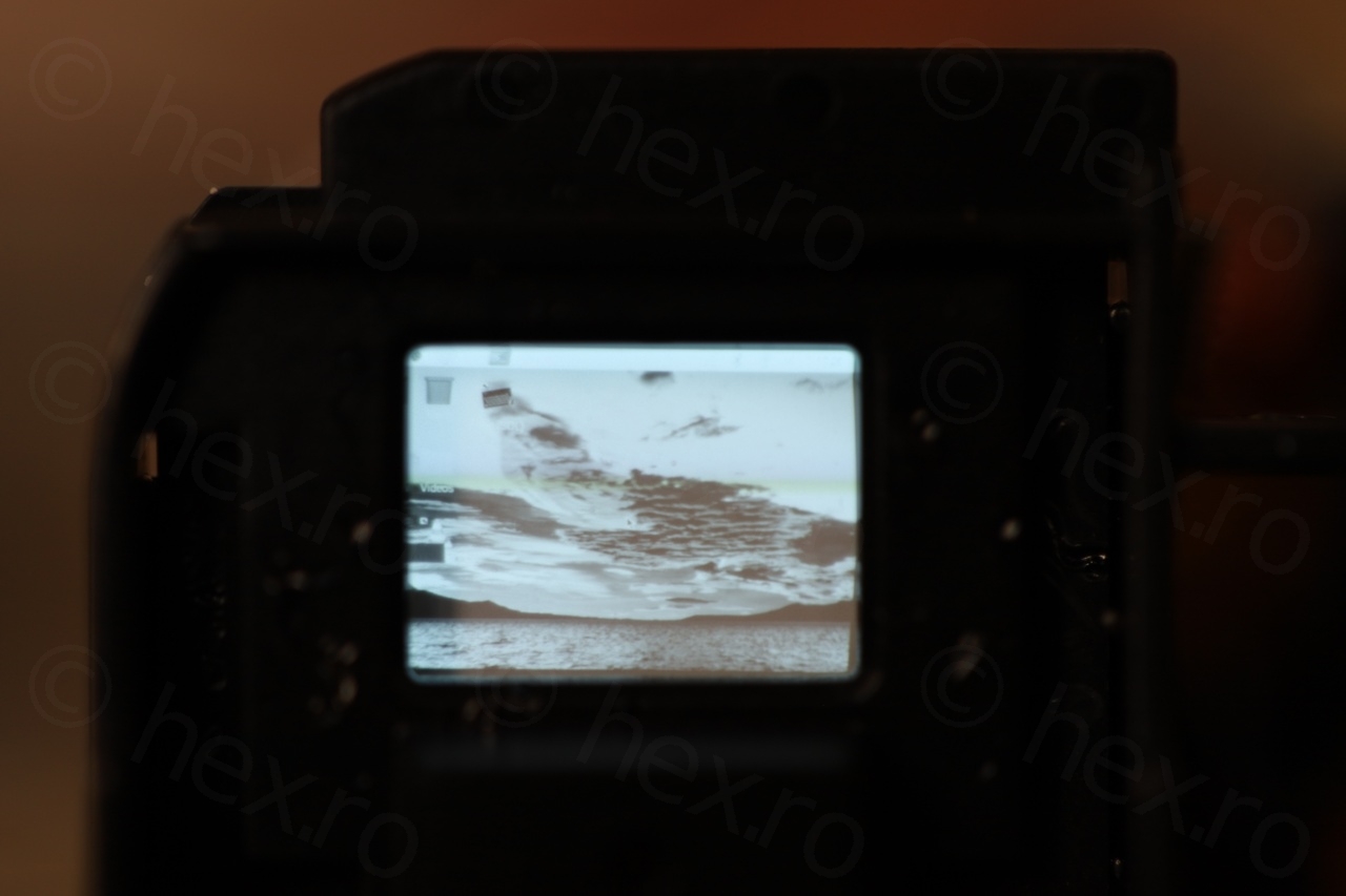
The second PIN that is unused (between VCC and Video IN PINs) is the one controlling the location of the brightness indicator – voltage controls the direction, connecting it to GND makes it go to the bottom of the image and VCC to the top:
Tests
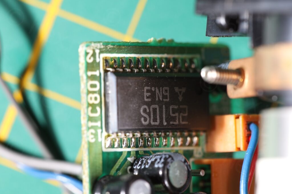
The board is driven by an AN2510S IC which was rather difficult to photograph:
Few more photos:
This was an interesting camera to take apart – a new CRT for the collection, clean boards with no bodges and the surprise with the white bar which required to consult the manual to make sense of it.
Leave a Reply