

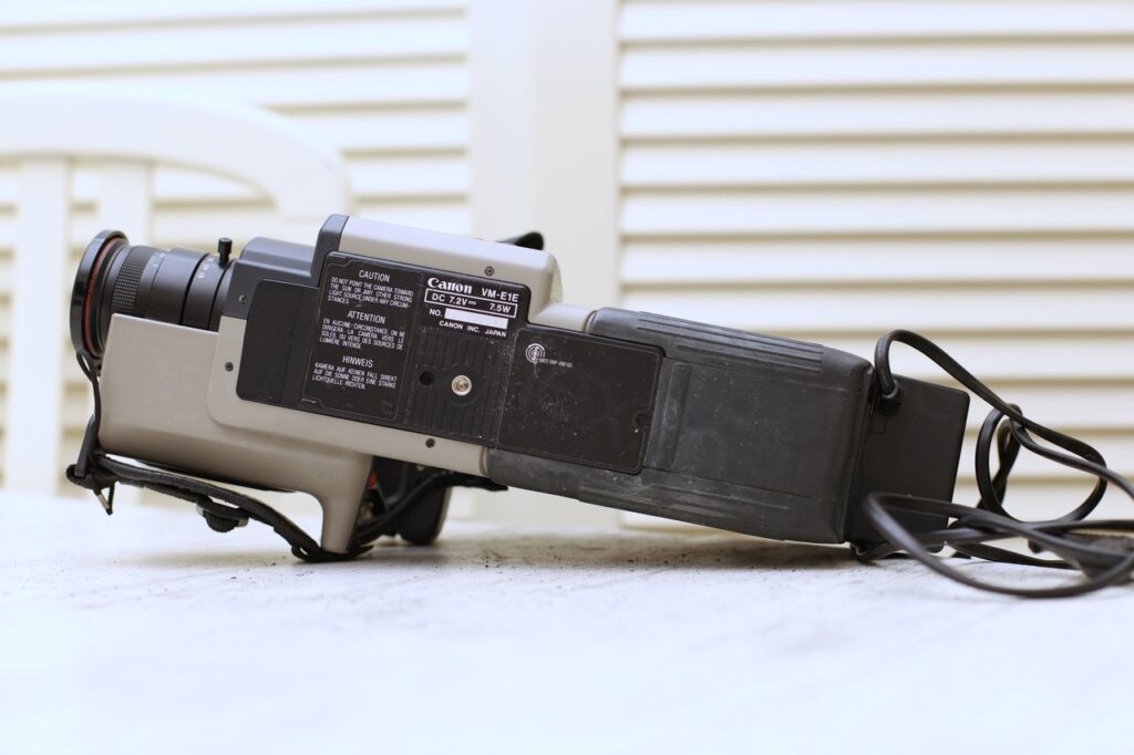
Found this mini CRT inside a Canon VM-E1 Camera that I picked up at a local flea market.
I was a little skeptical if it is worthy the purchase – experience with old Canon cameras taught me that the circuitry is not necessarily straight forward and it may be tedious to power up the Electronic View Finder.
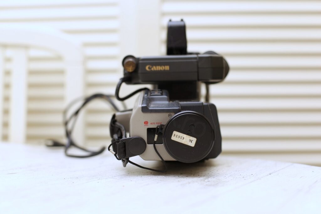
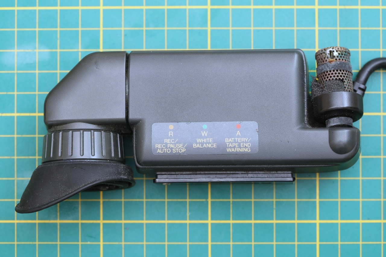
Camera overview
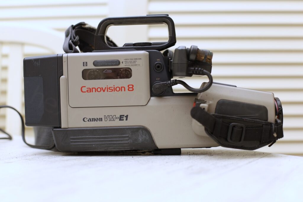
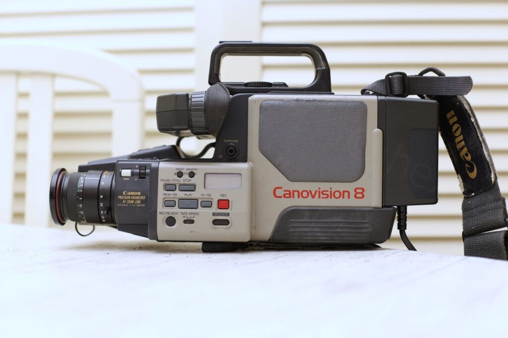
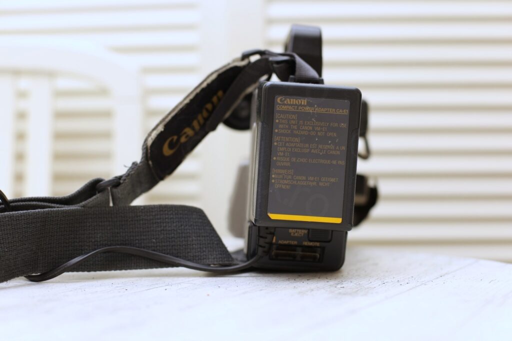
Since the camera was provided with a battery adapter that could be plugged – I decided to at least try to see if there’s some life left in the CRT. Surprisingly, it lit – and even if no image appeared, it was obvious that at least the high voltage is present! Good news.
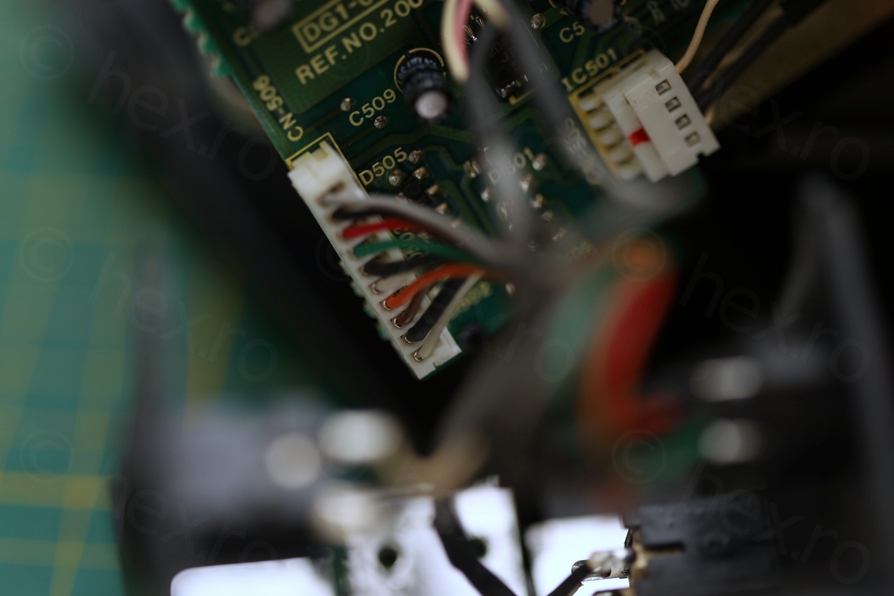
For most of the cameras, it is easy to identify the signal pins that control the EVF (the CRT) – at least VCC, Ground and Video IN. But in some complex cameras, the control signals are not so obvious. With camera still intact, I took a reading of the voltages present on the EVF plug:
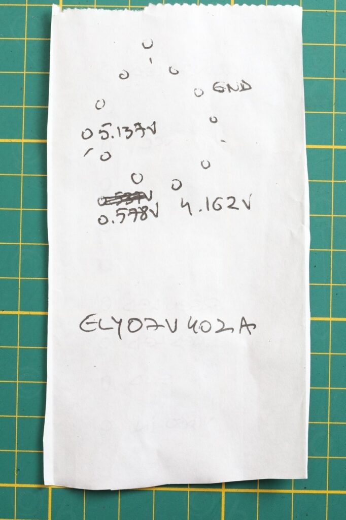
These values could come in handy later I figured, but they didn’t. Camera is standard and it is easy to identify the control pins. No hidden gotchas.
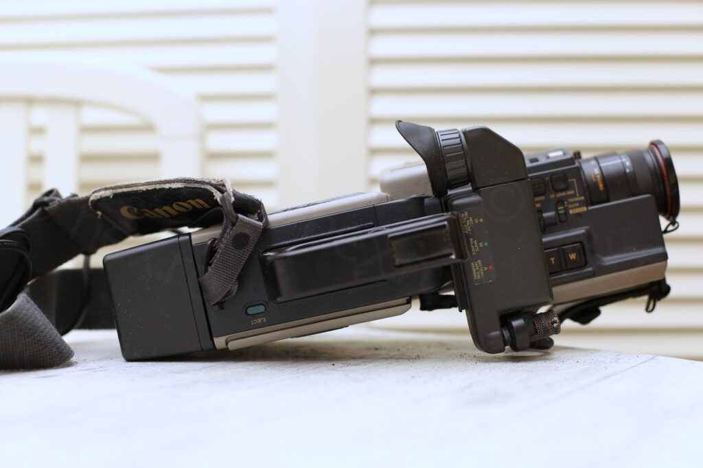
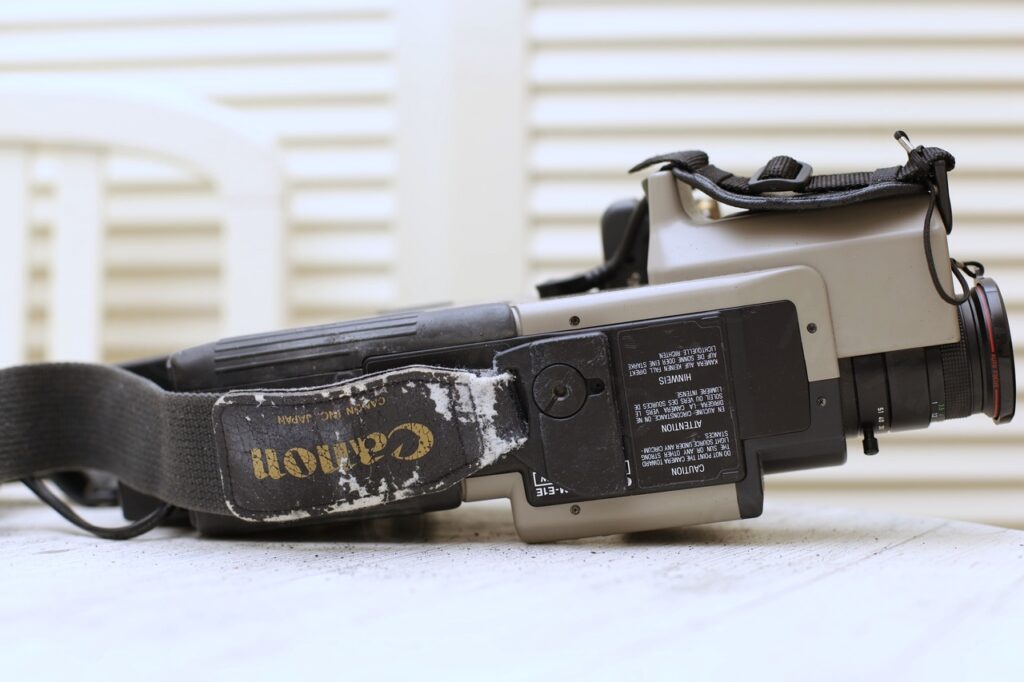
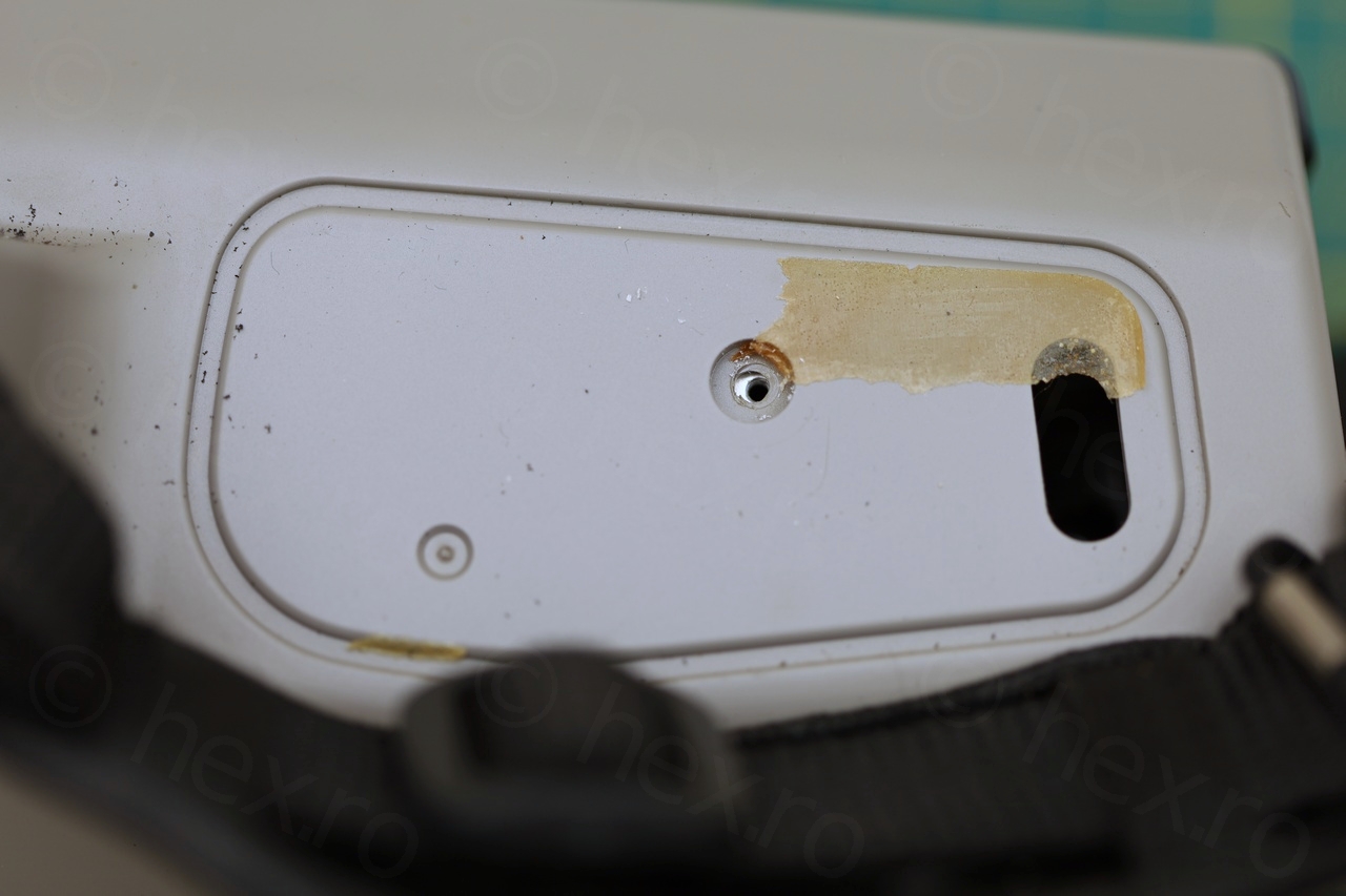
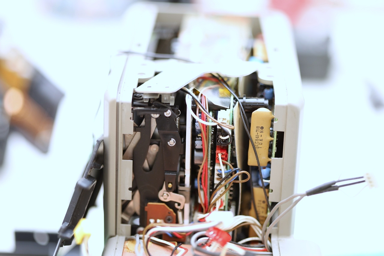
Dismantling the camera was easy, although many screws are under the soft rubber pads. Goal was to reach the EVF plug – much easier to send the signals through its own connections.
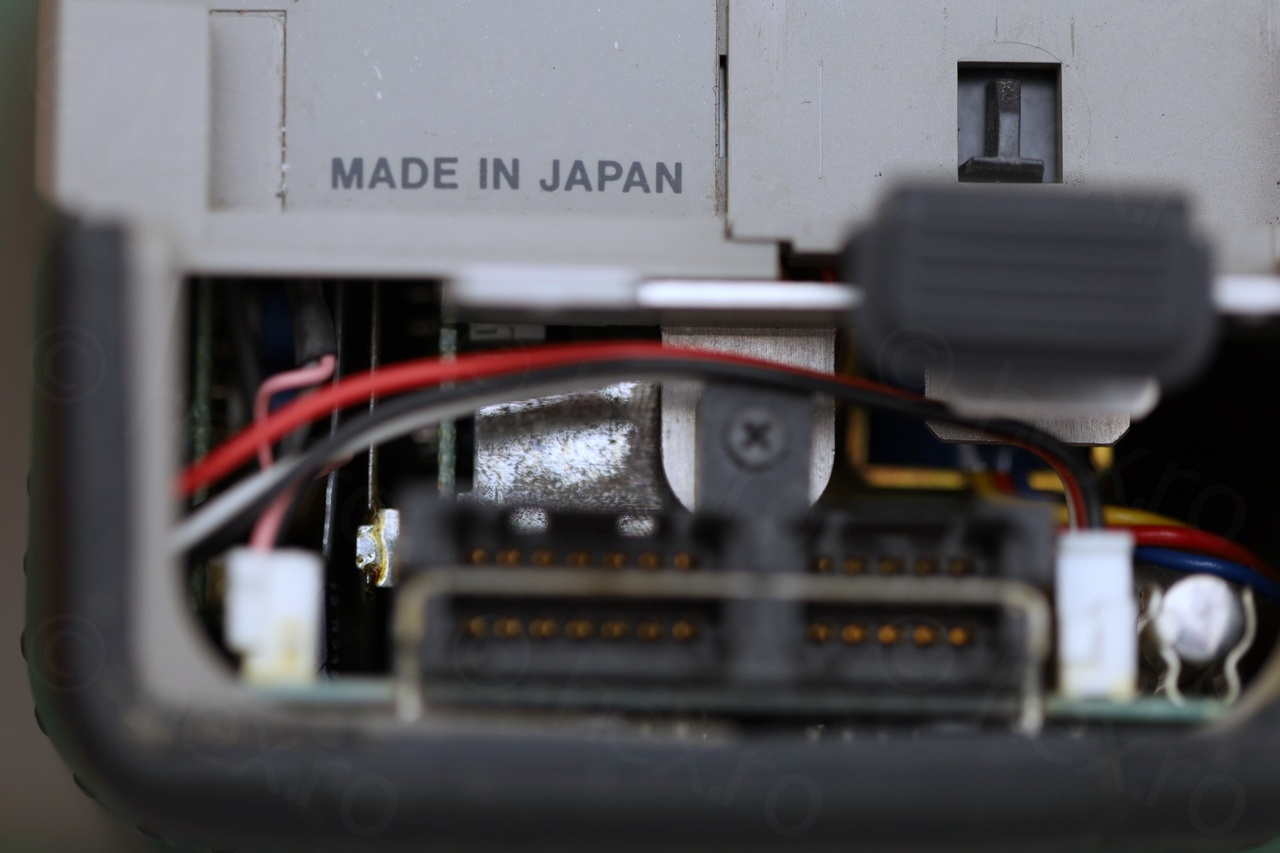
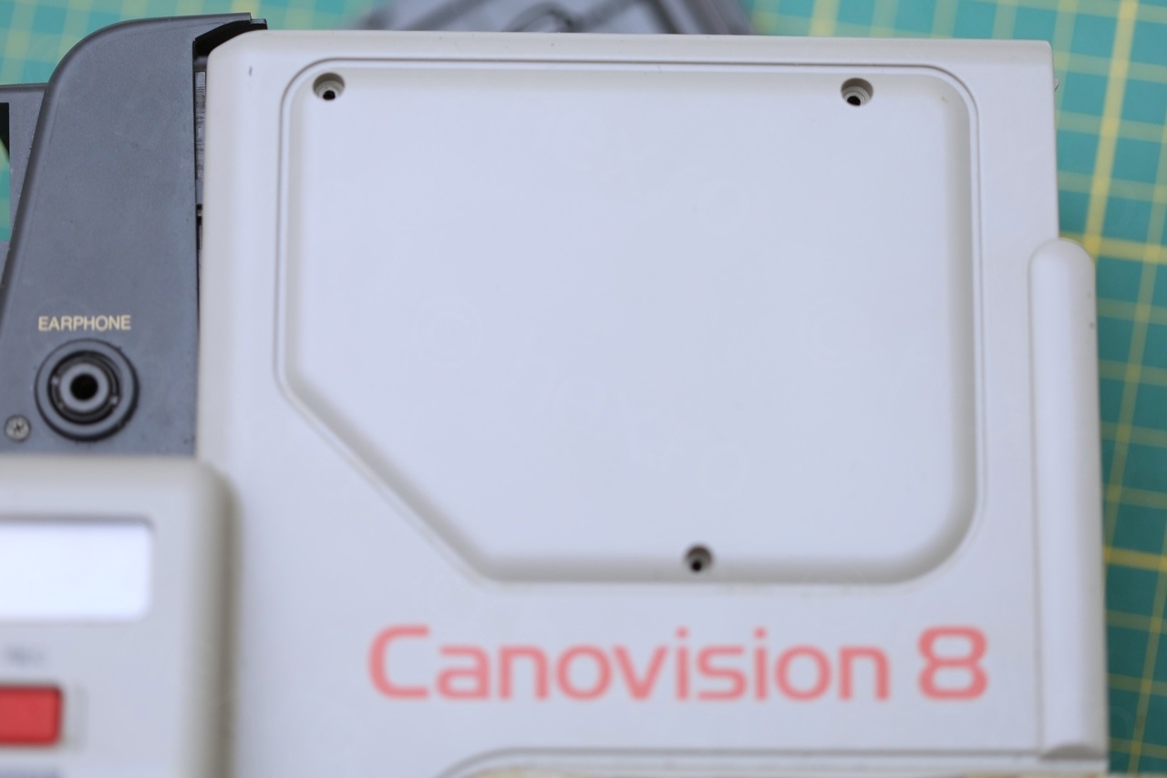

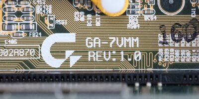
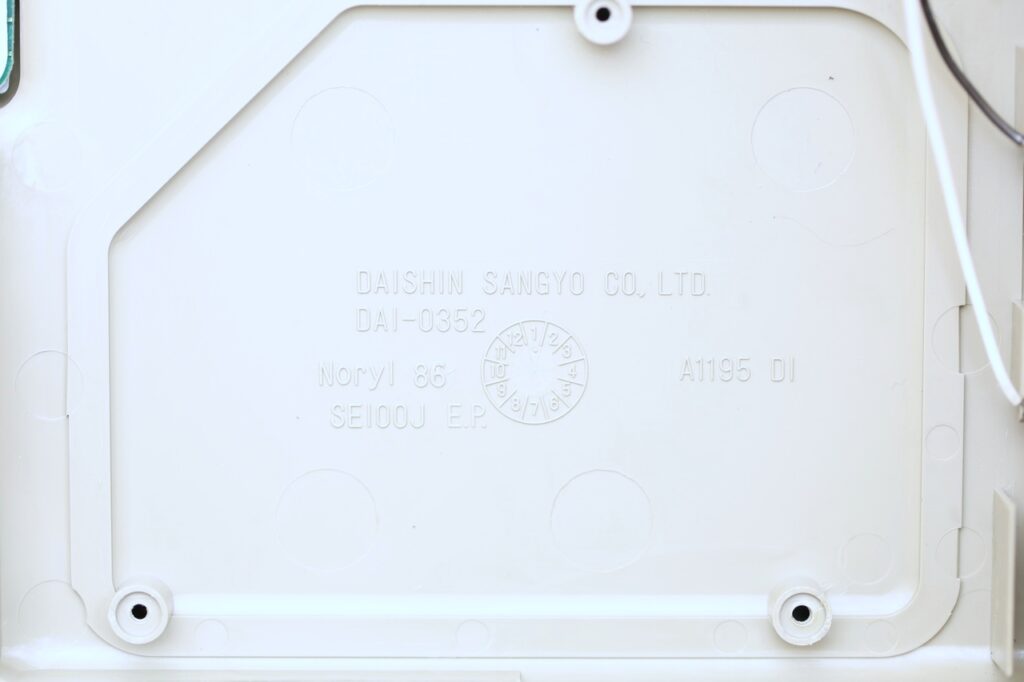
It seems camera was made around 1986:
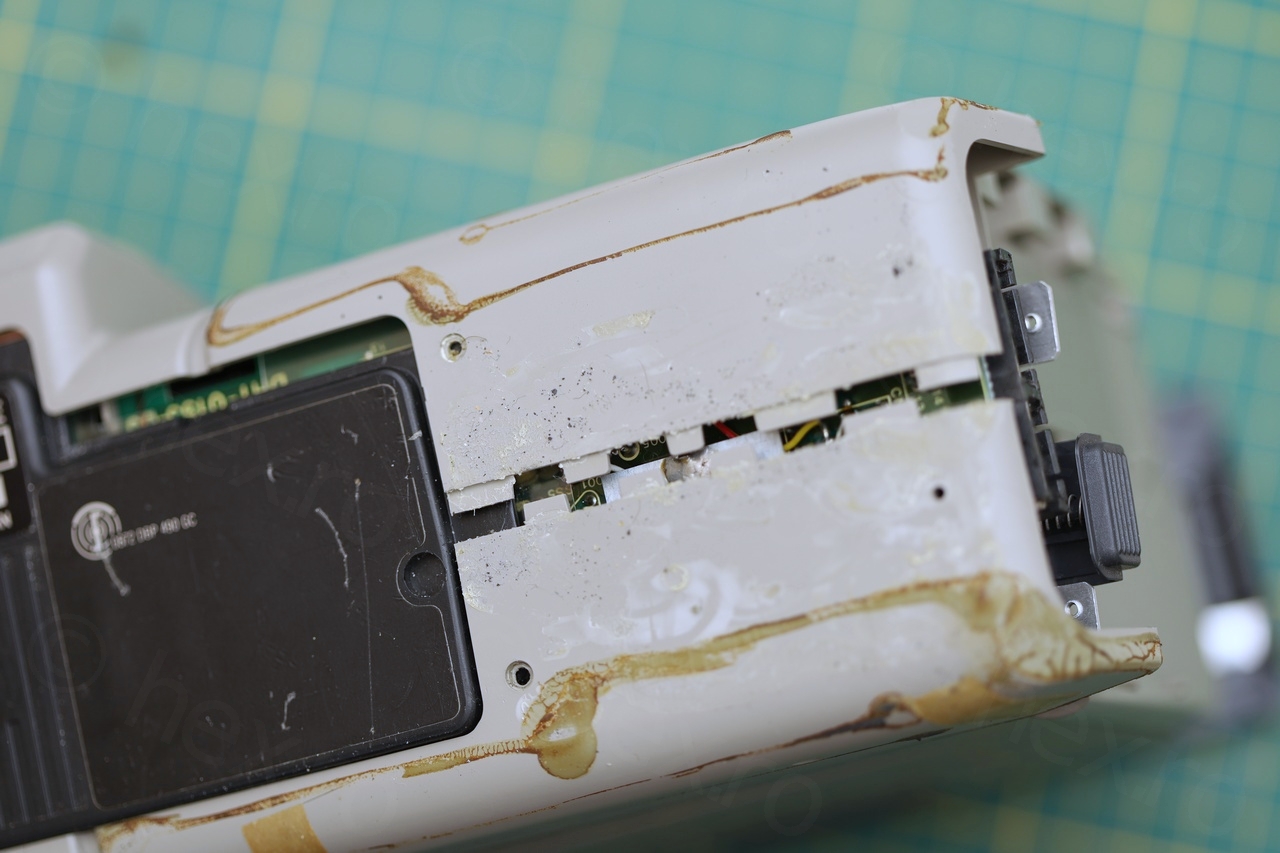
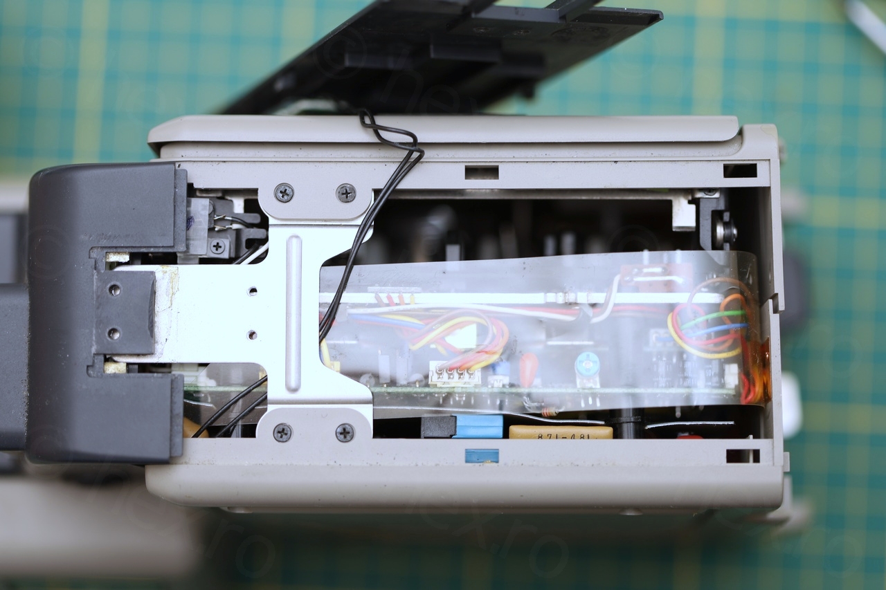
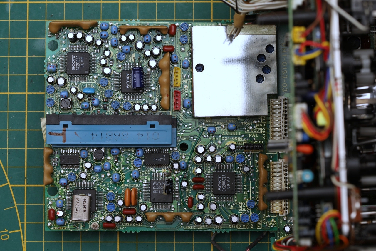
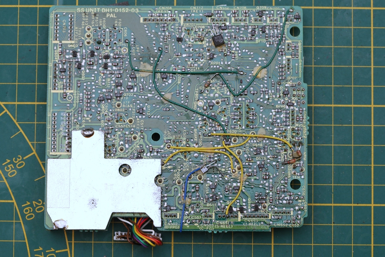
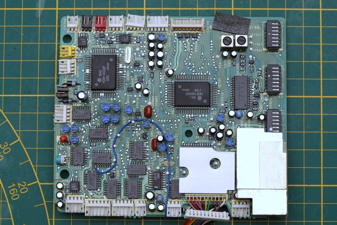
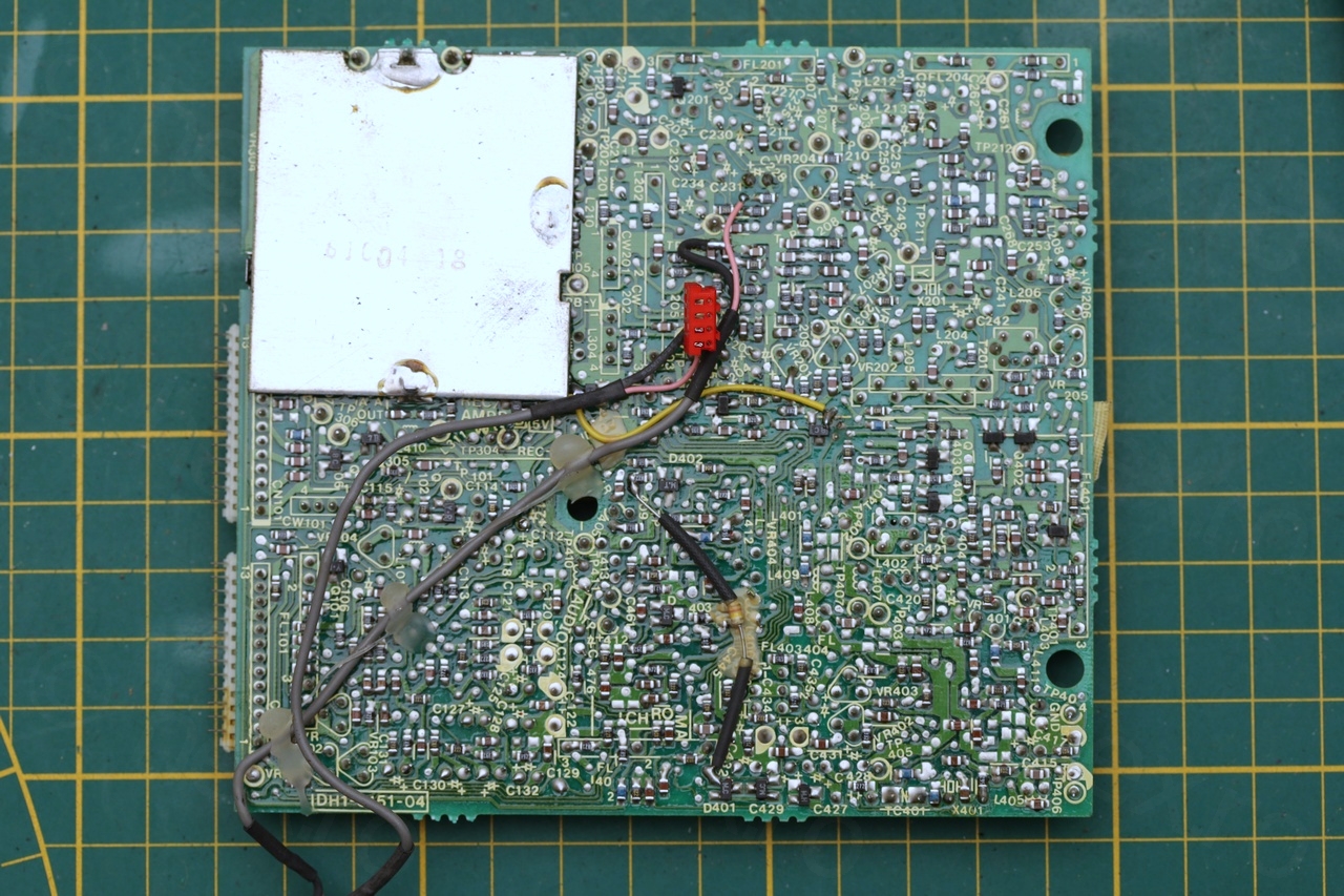
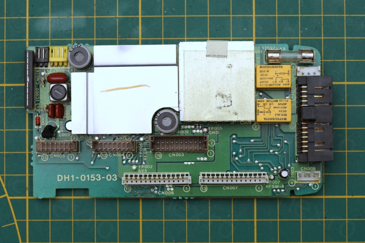
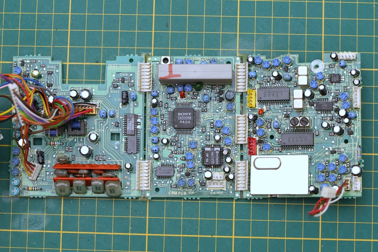
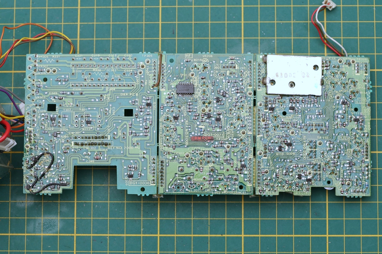
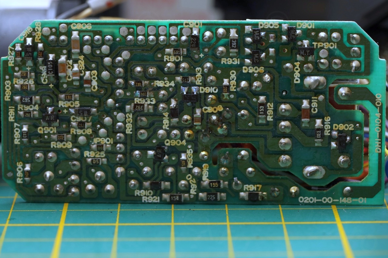
Boards were clean with not too many bodges, and I was surprised to find so many Sony ICs inside.
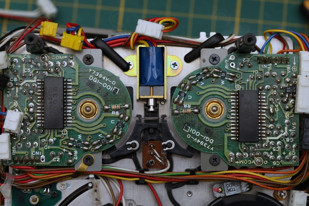


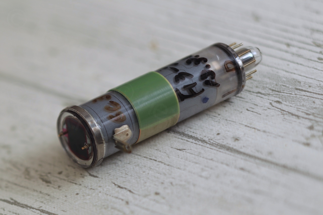
One interesting find was the imaging sensor. I don’t know why, but my expectations were that the camera has a CCD sensor (it does look very professional) however, upon examination – the imaging sensor is a Saticon S3562 tube.

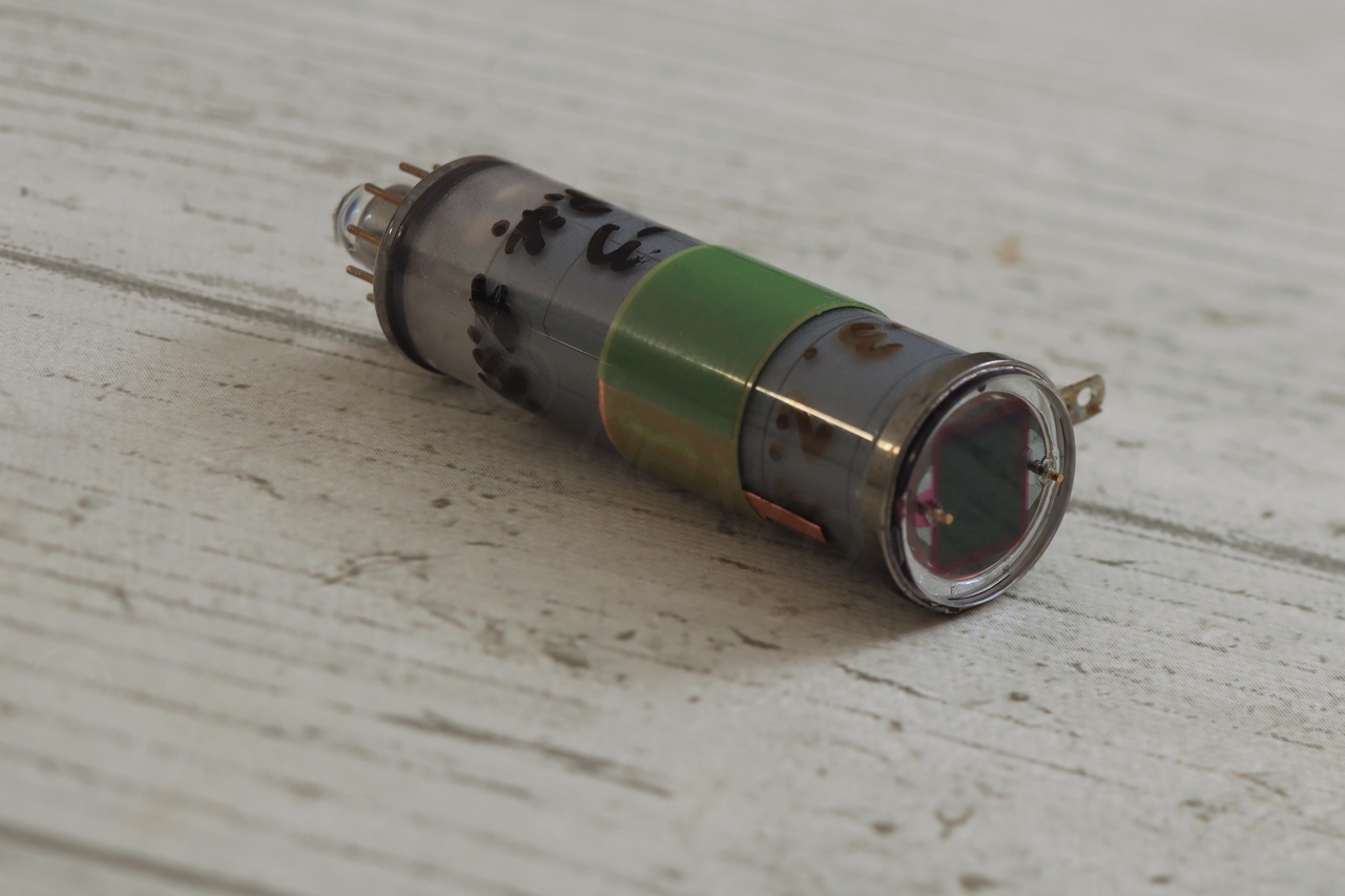


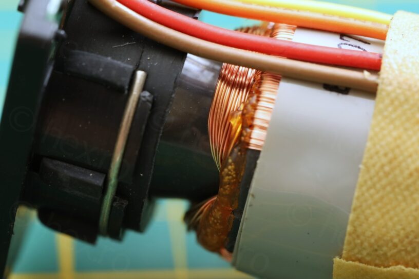
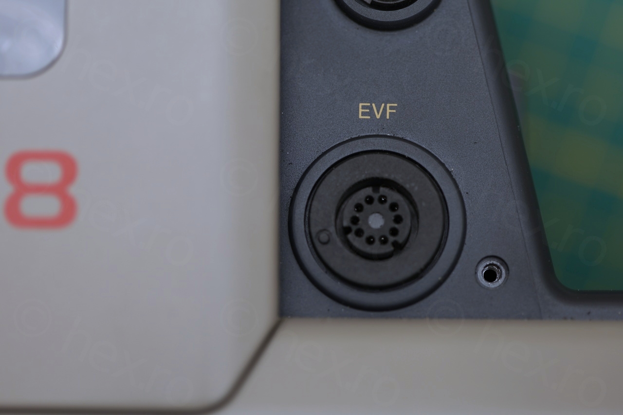
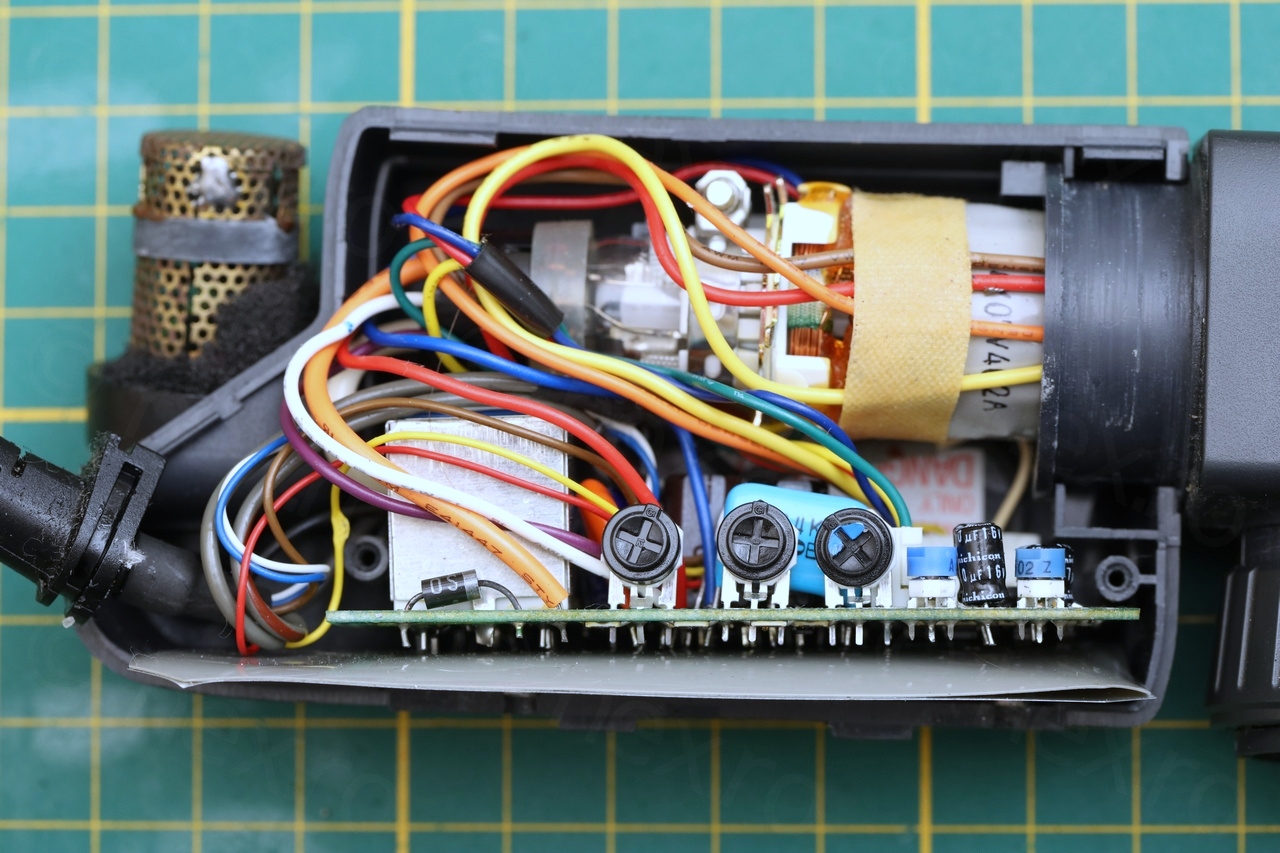
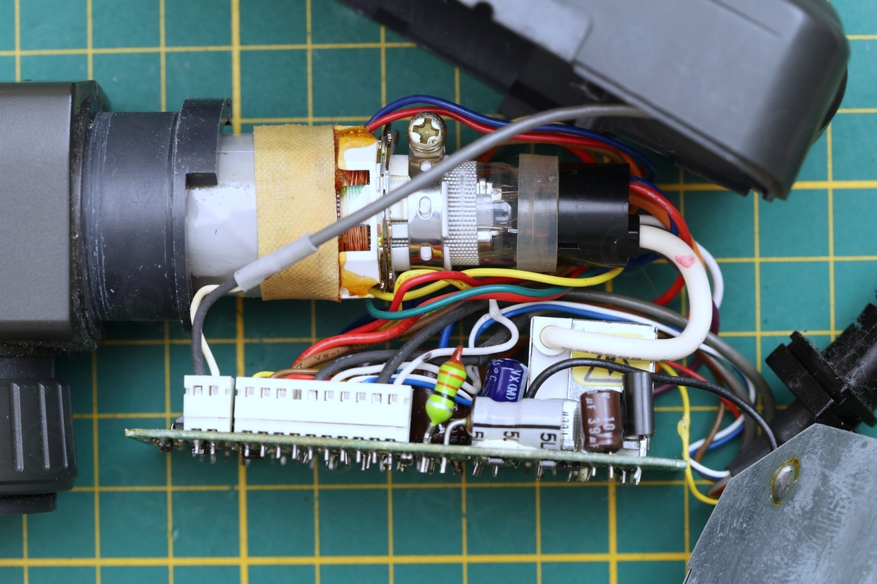
EVF Unit
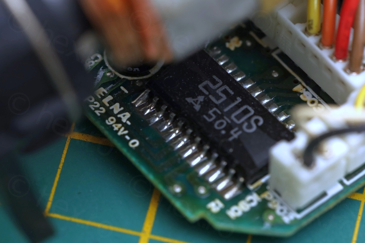
I have made my way to the EFV unit and took it apart. It contains an ELY07V402A mini CRT driven by the standard AN2510s IC. I appreciated the warning inside the EVF case: “HIGH VOLTAGE DANGEROUS. DISCHARGING OR METERING OF SECOND ANODE LEAD MUST BE TO FBT SHIELD CASE ONLY”. In contrast with present day approach of “Do not open, no user serviceable parts inside” …

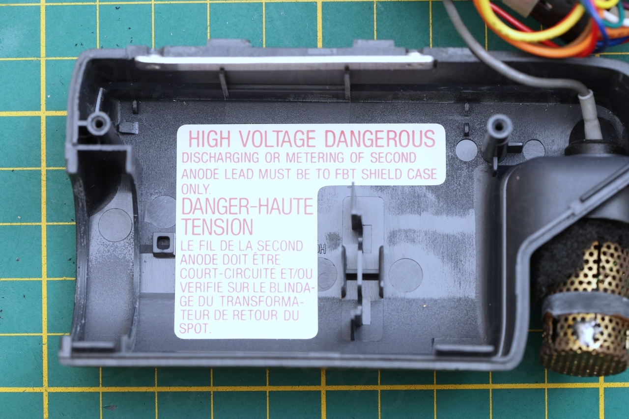

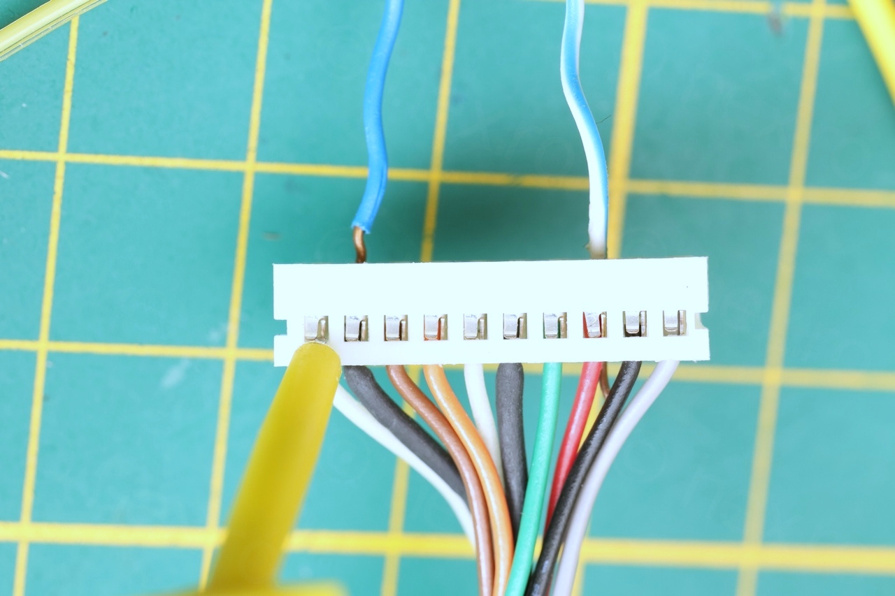
Identifying the input pins was easy with a continuity checker – the GND pin is directly connected to the FBT’s case, VCC goes the FBT pins that are not connected to GND, but still have continuity to the input plug. Then trial and error to identify the Video IN pin.
Assuming the camera’s EVF plug is used (with its own connector), I made this wiring diagram watching from the connector point of view:
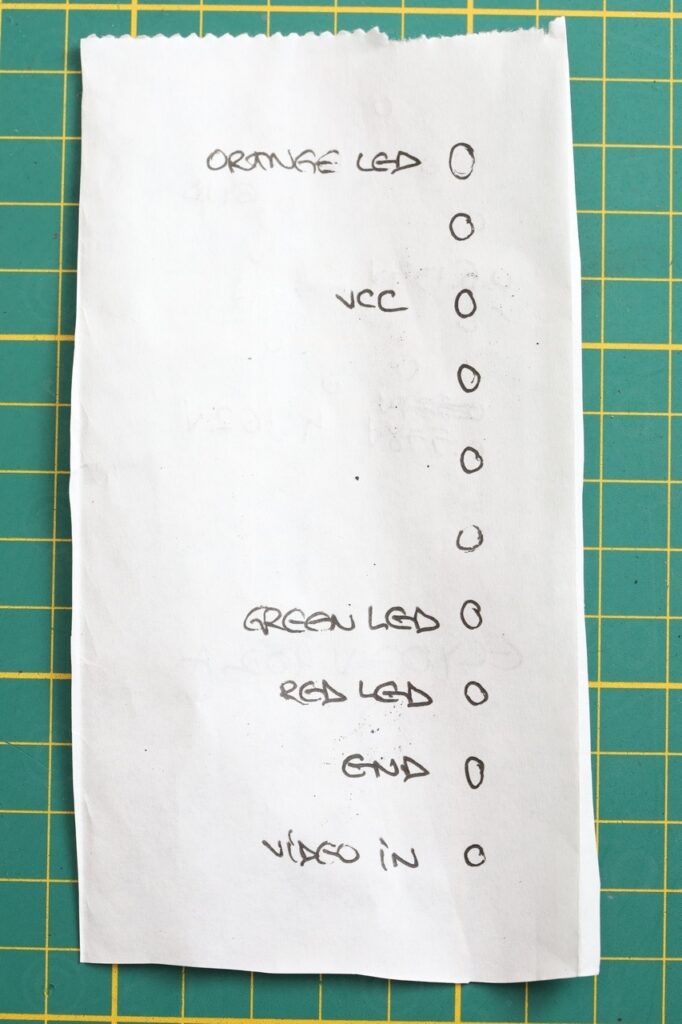
Image quality is OK – and sharpest when VCC is 5.1V (when it draws about 115mA):
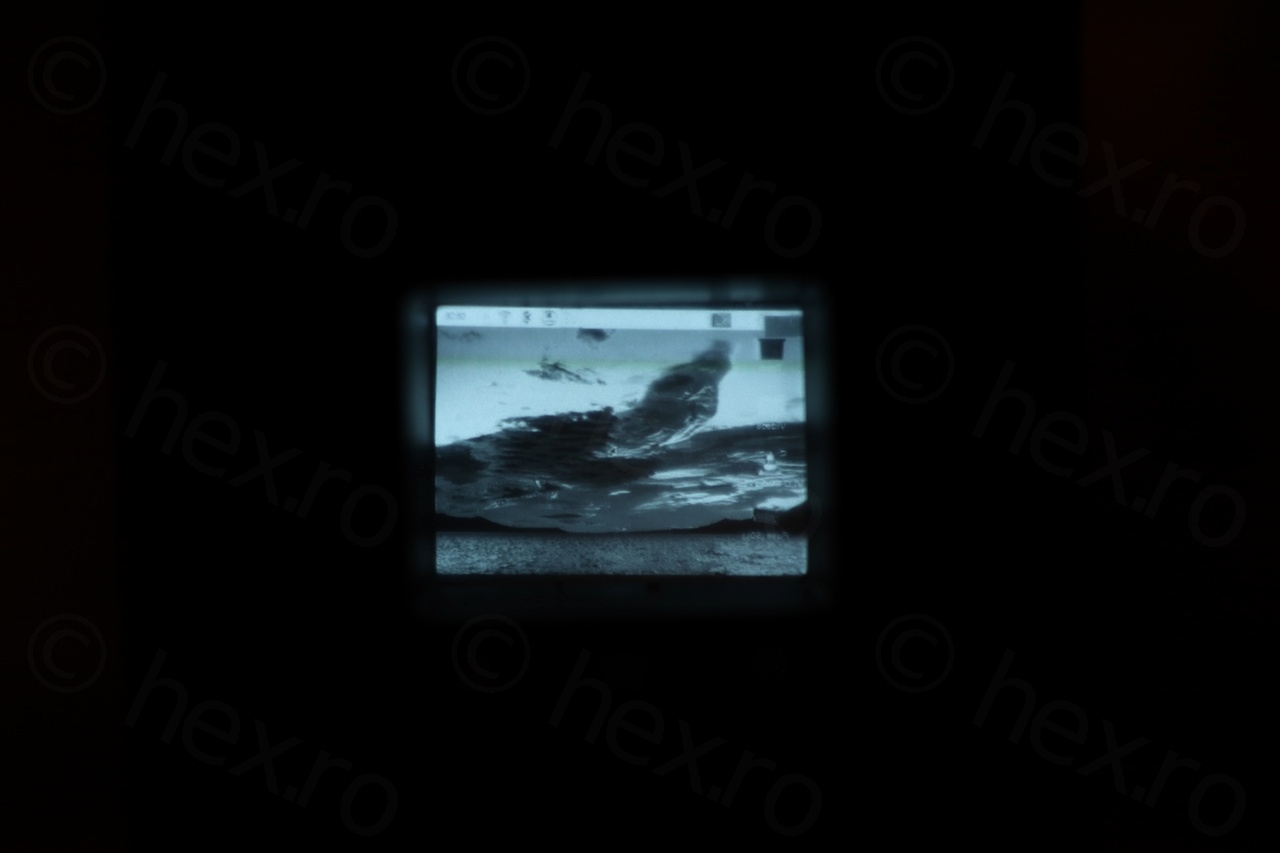
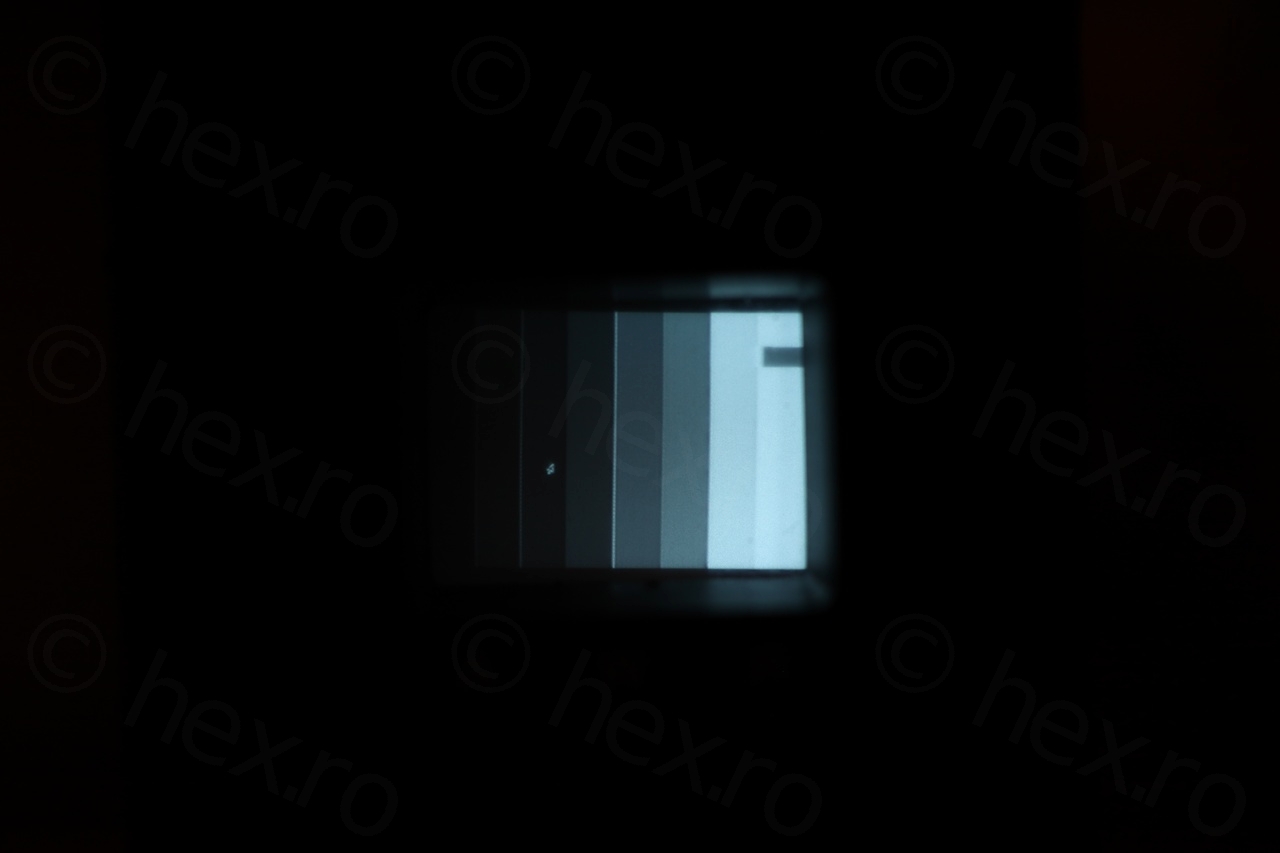
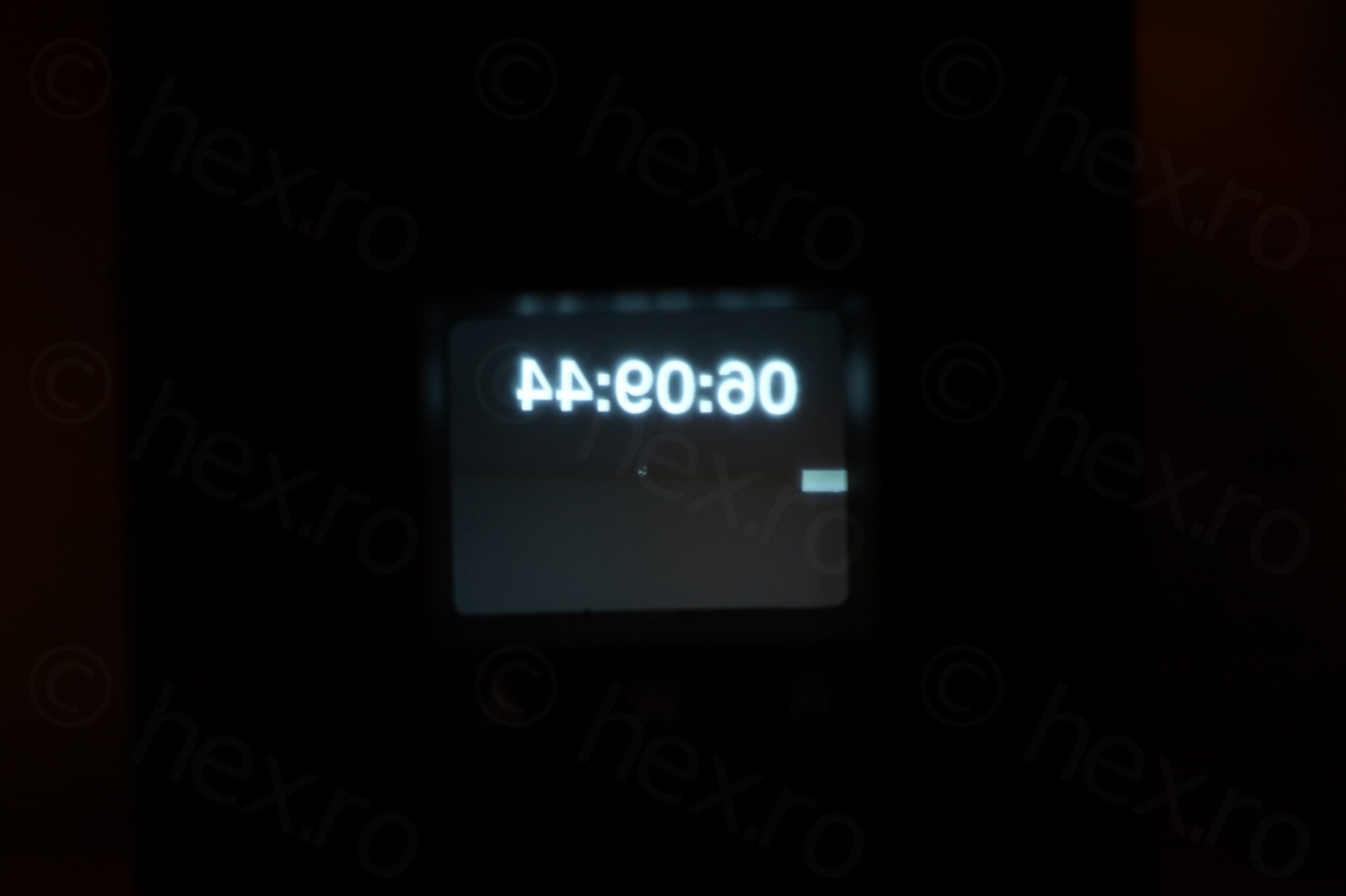
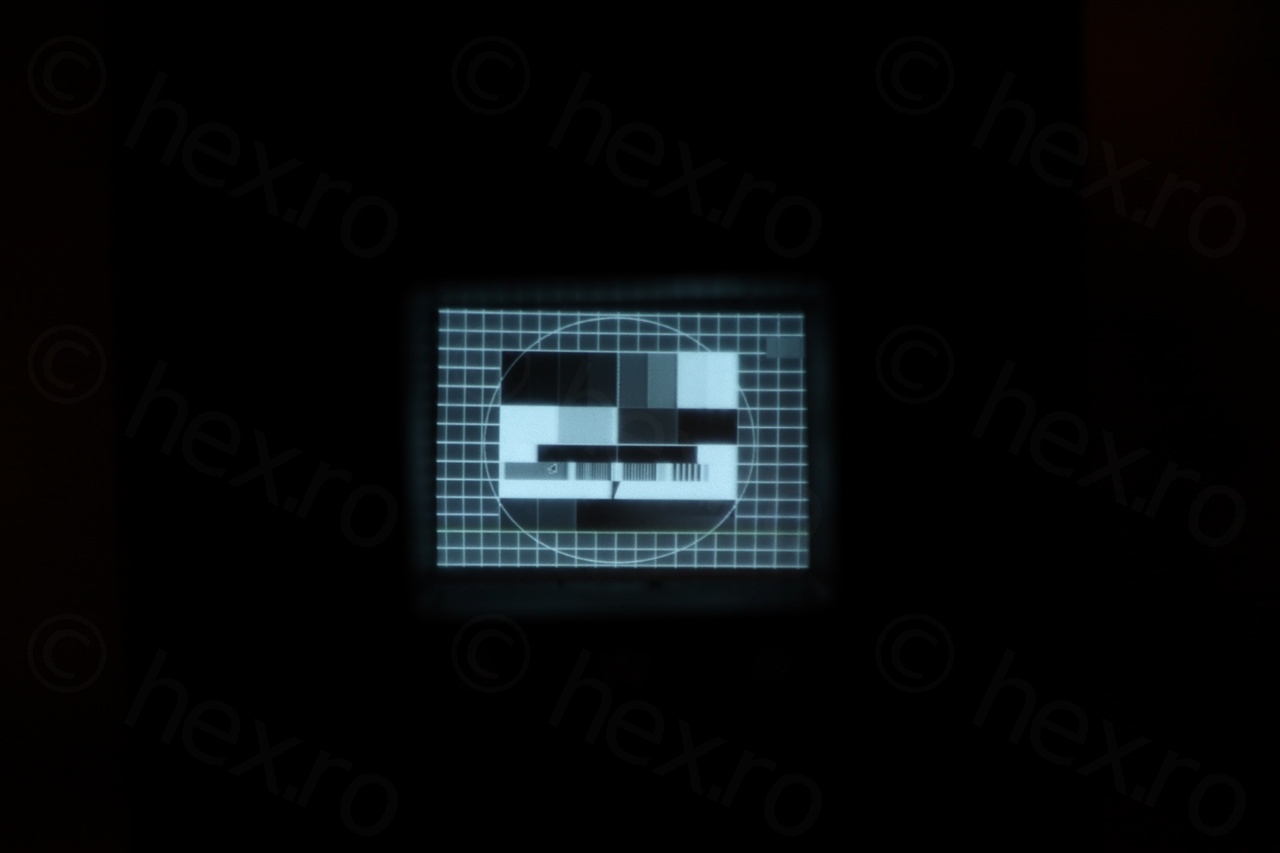
Few more closeups with the CRT:


In conclusion, an interesting camera to take apart – I was able to salvage also some parts that could come in handy in the future (like small heat-sinks for transistors / voltage stabilizers, silicone shafts for some higher voltage capacitors and so on, few potentiometers etc).
Leave a Reply