


I found this mini CRT inside a Canon E300 camera that I got at a flea market.
Although I am curious about the Canon camcorders, I start to get weary about buying old ones. Some that I took apart had bad capacitors (at least in the Electronic View Finder module).
This one … was one of the worst.
Table of Contents
- Canon E300 Overview
- Electronic View Finder
- Powering on the EVF unit
- Voltage levels
- Brightness control
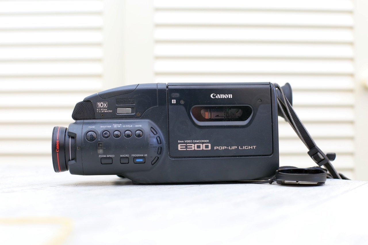
Canon E300 Overview
Camera looked well maintained, but it did not power up. Which in my experience it means capacitors, but let’s not assume anything yet:
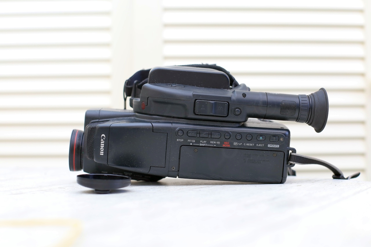
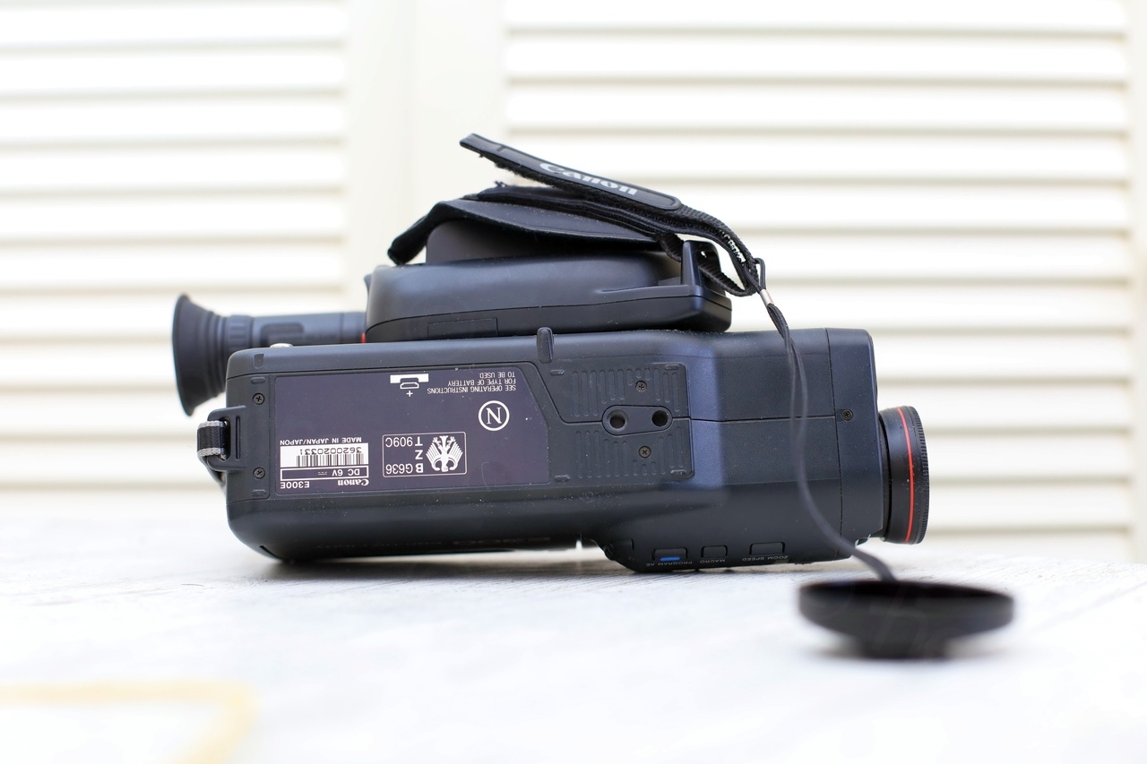
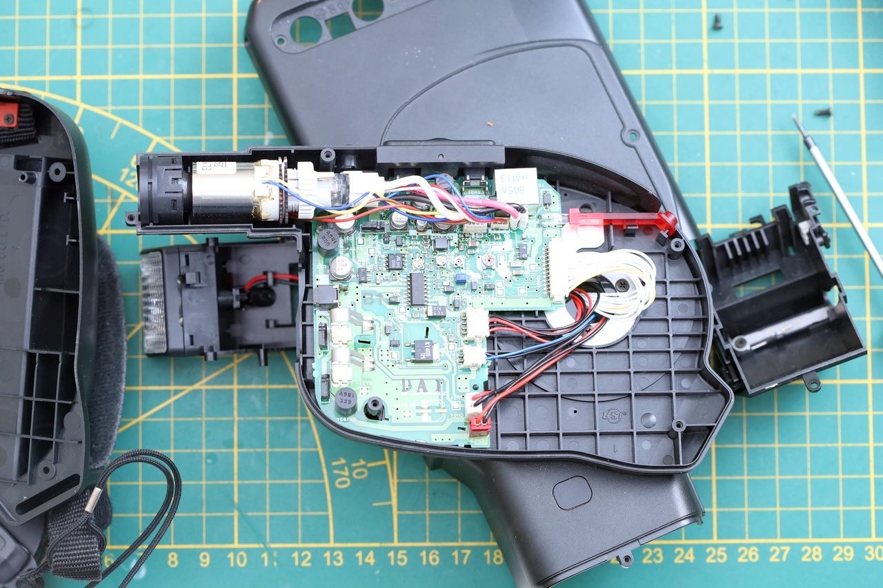
Opening the camera was a breeze, very easy to get into – no hidden catches:
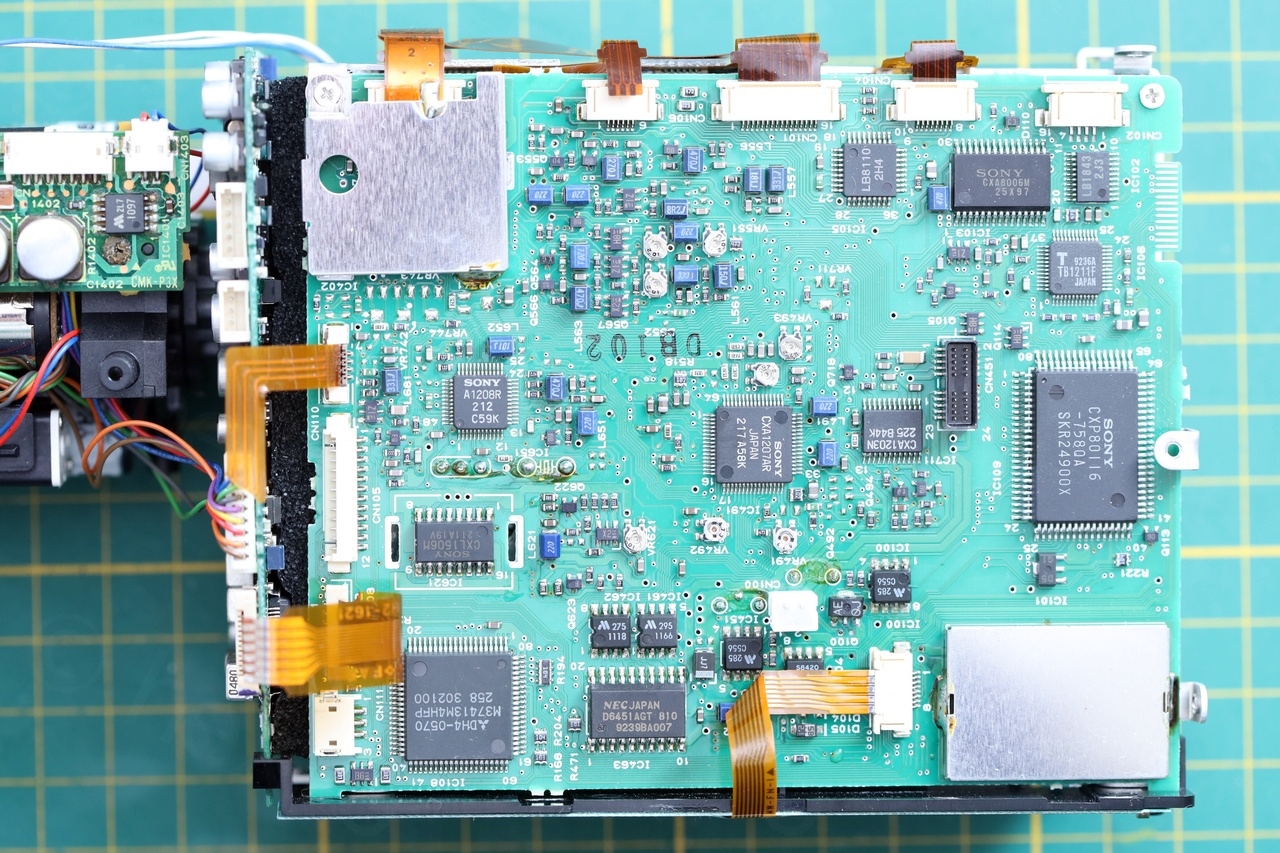

Camera did not anything worth noting, except many SMD capacitors and many small miniature potentiometers on the motherboard. No bodges for example.
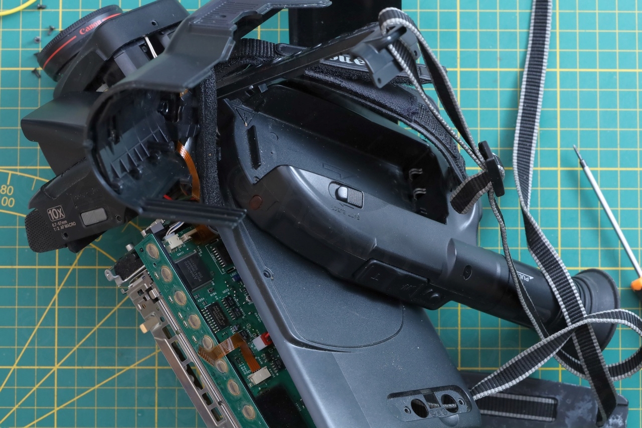
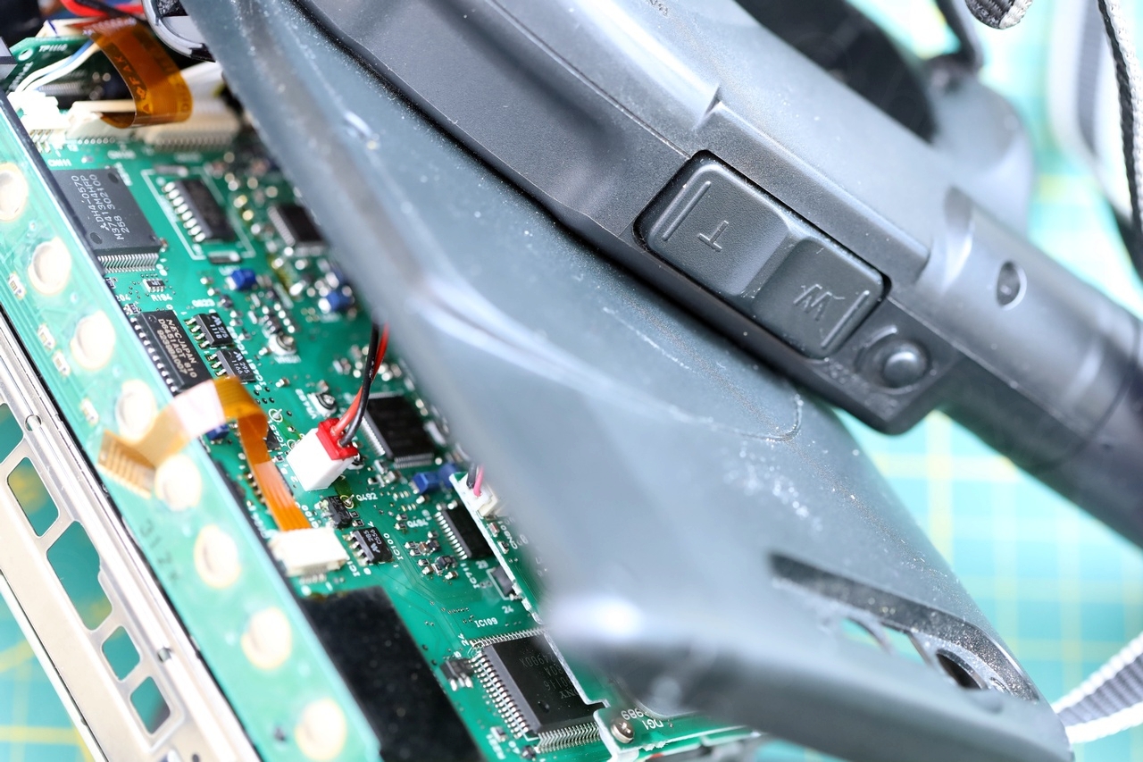
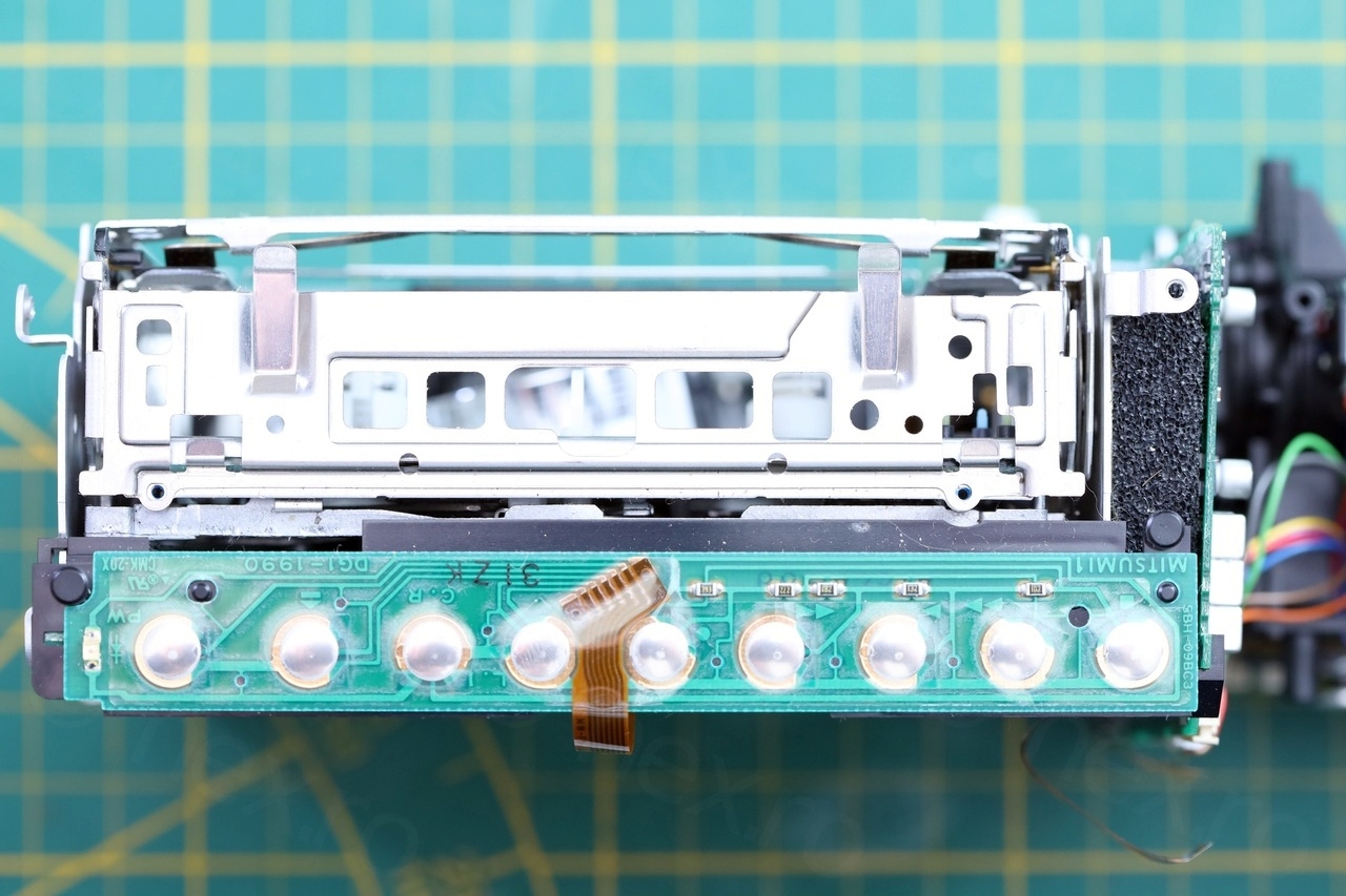
Electronic View Finder
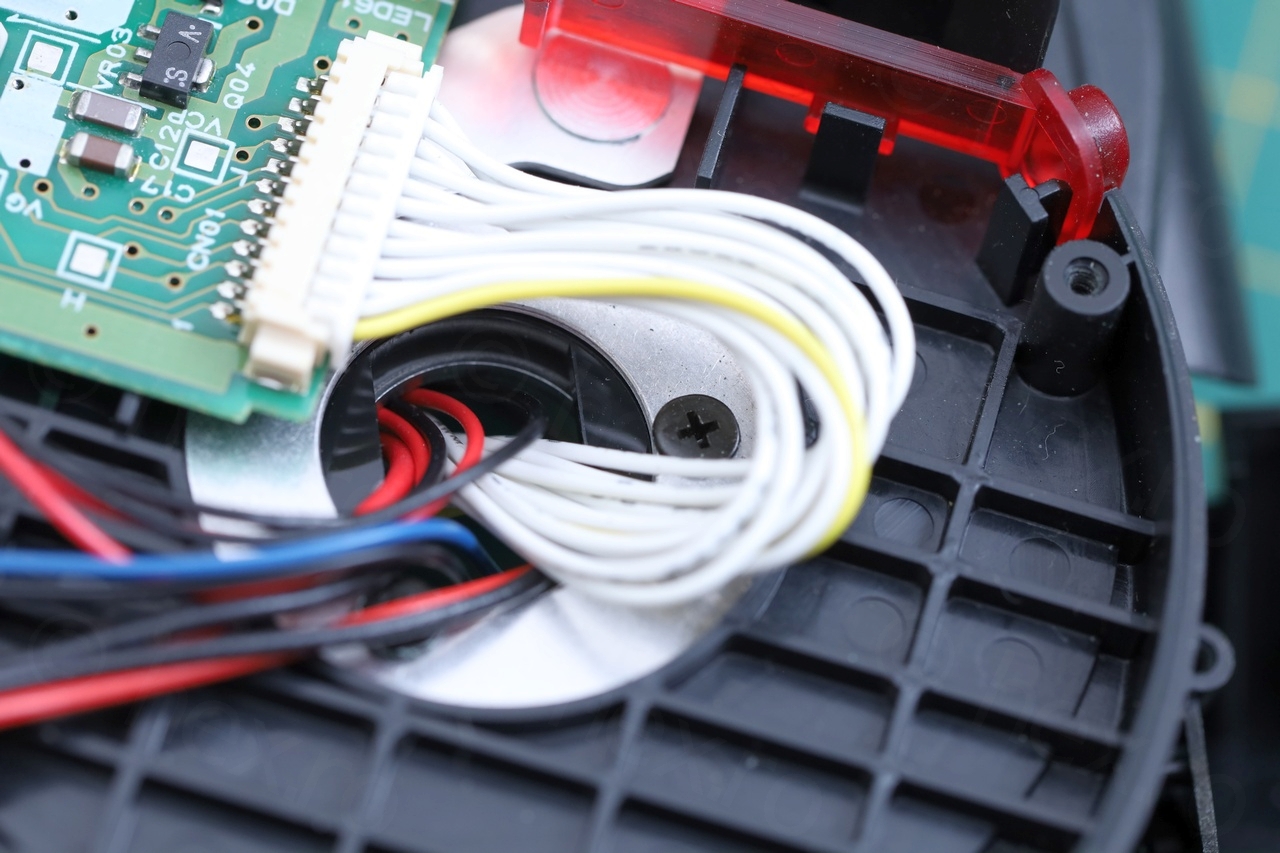
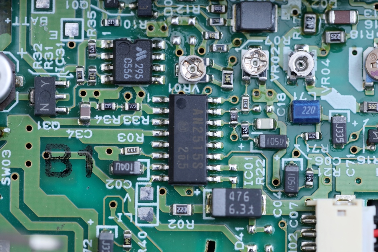
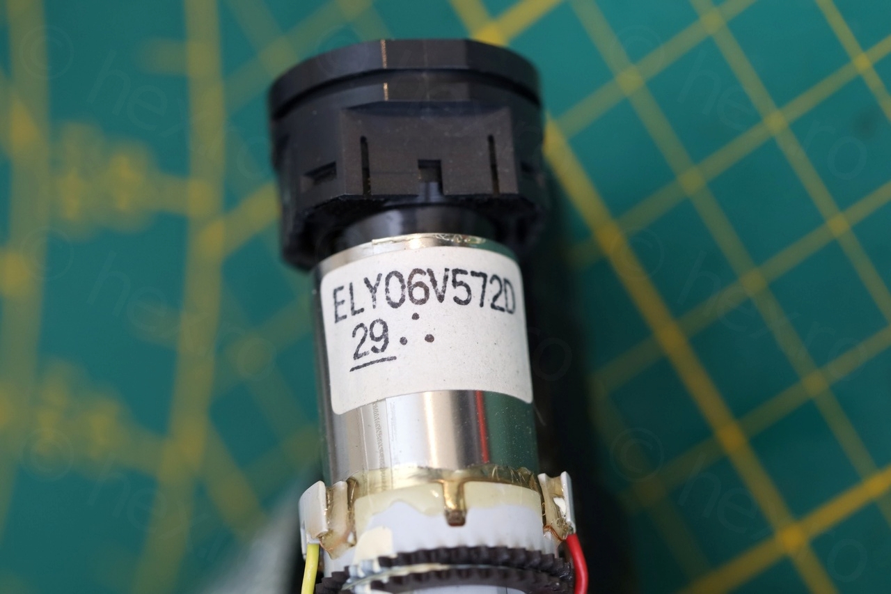
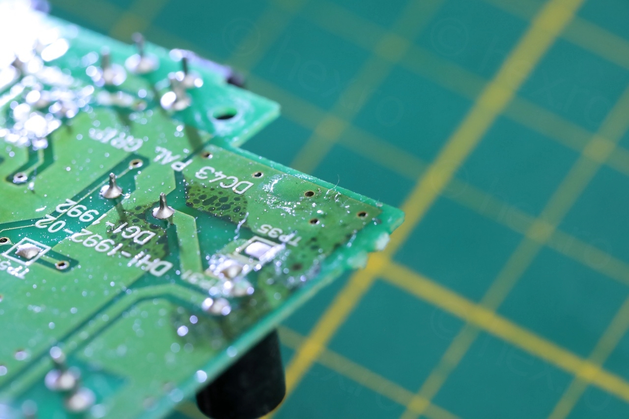
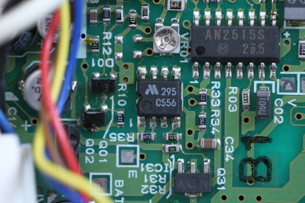
Getting access to the EVF unit was also very easy, 5 screws in total. It is driven by an AN2515S IC containing the ELY06V572D mini CRT:

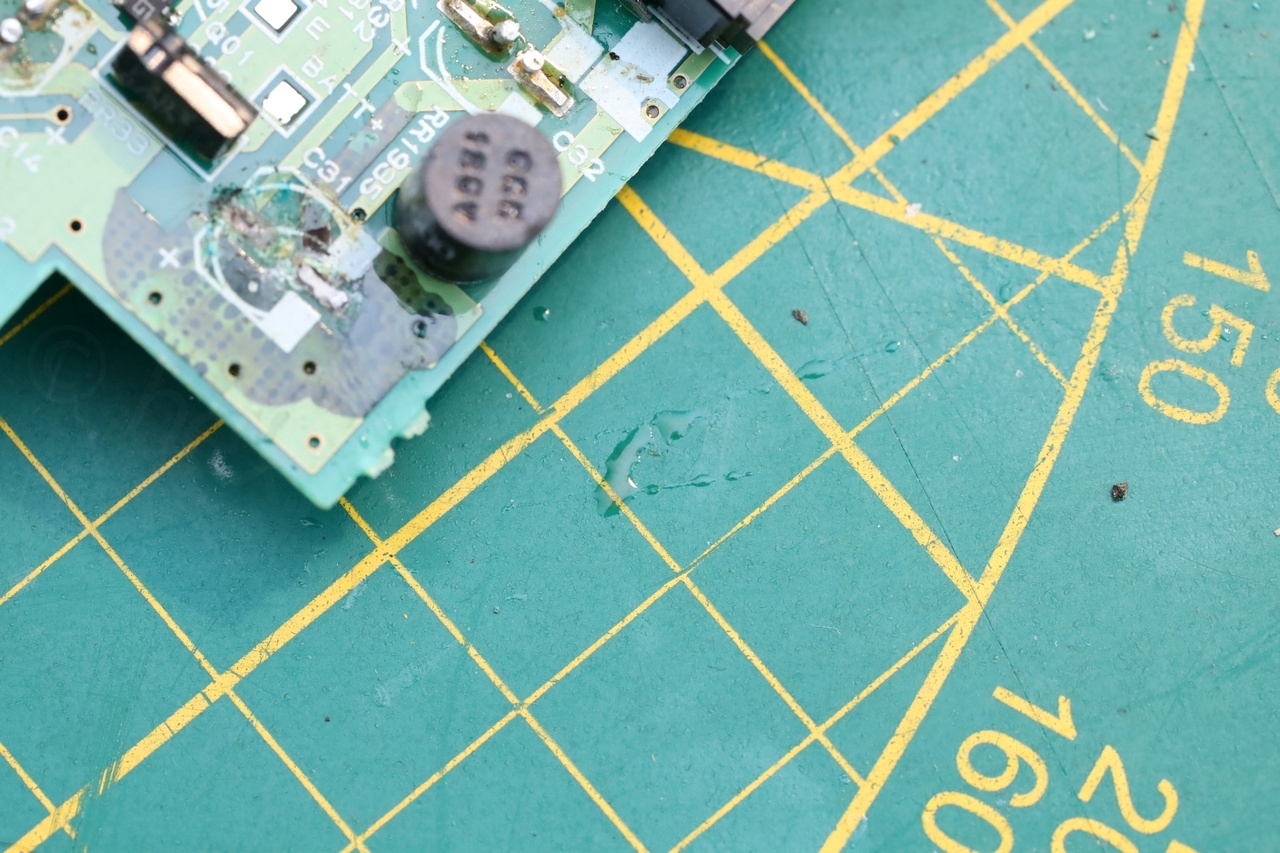
As I was getting ready to identify the pin-out (which also was a challenge in itself), I started noticing fresh electrolytic capacitor leaks and blue corrosion 🙁
I wonder if they leaked as I tried testing the camera before I took it apart, since liquid was really in a small puddle in the corner of the board. Thus, to even stand a chance to have an image, I had to replace the capacitors.
But first, few photos with the before, the cleanup and the after:
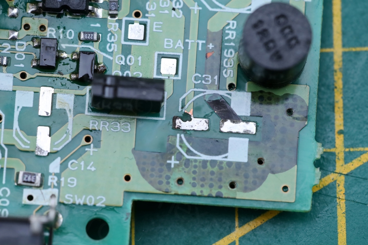
Leaky Electrolytic Capacitors
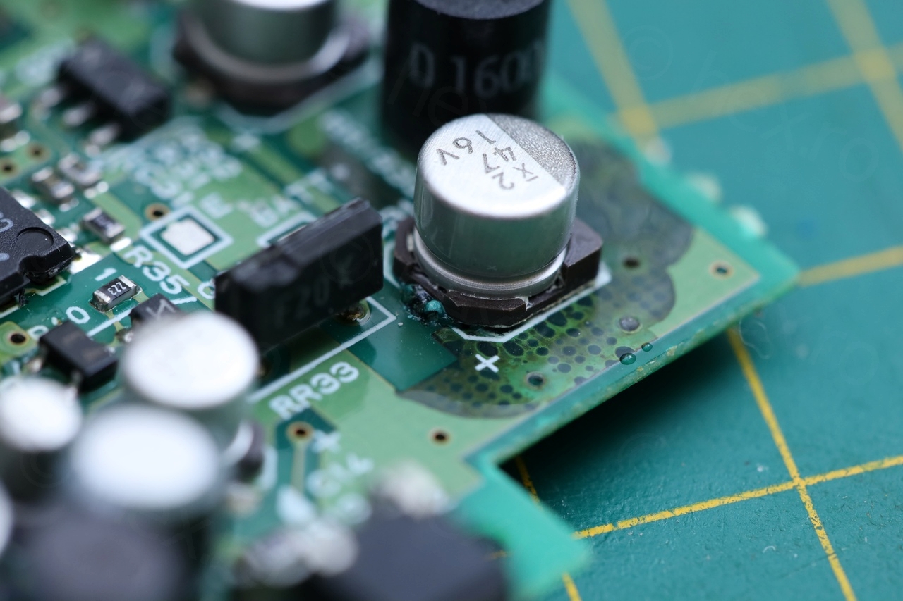
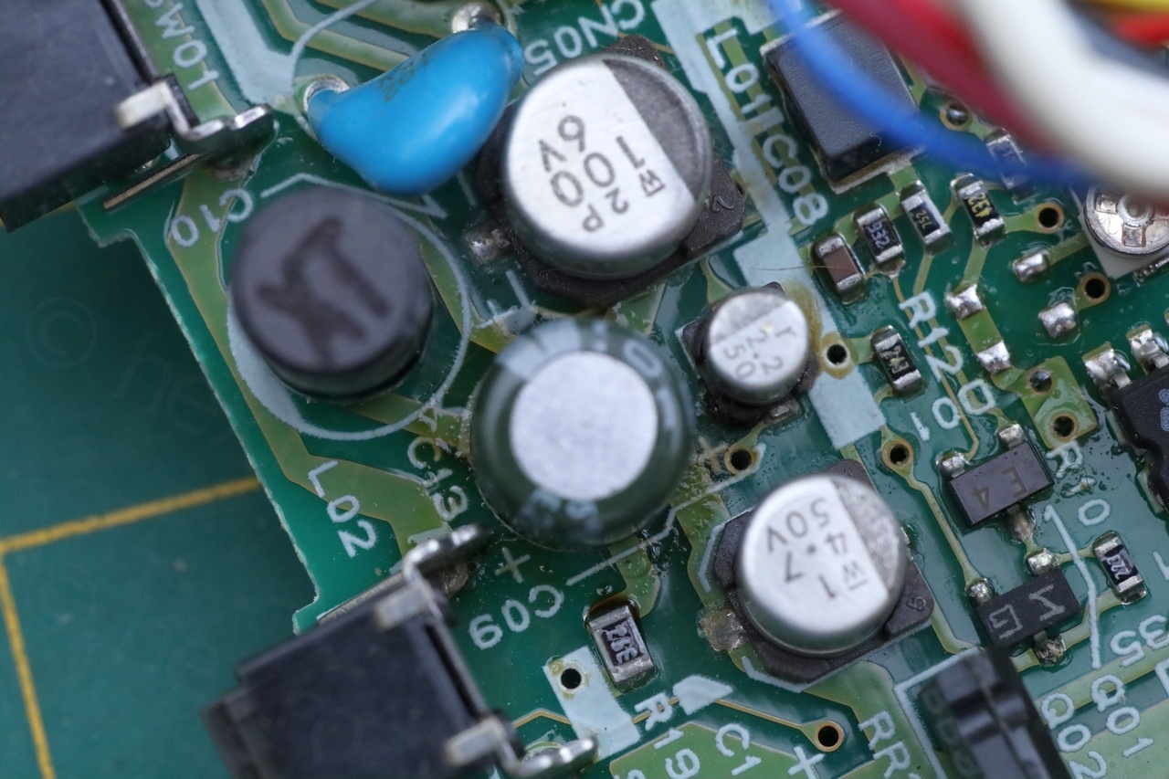
I never saw puddles of electrolyte 🙁
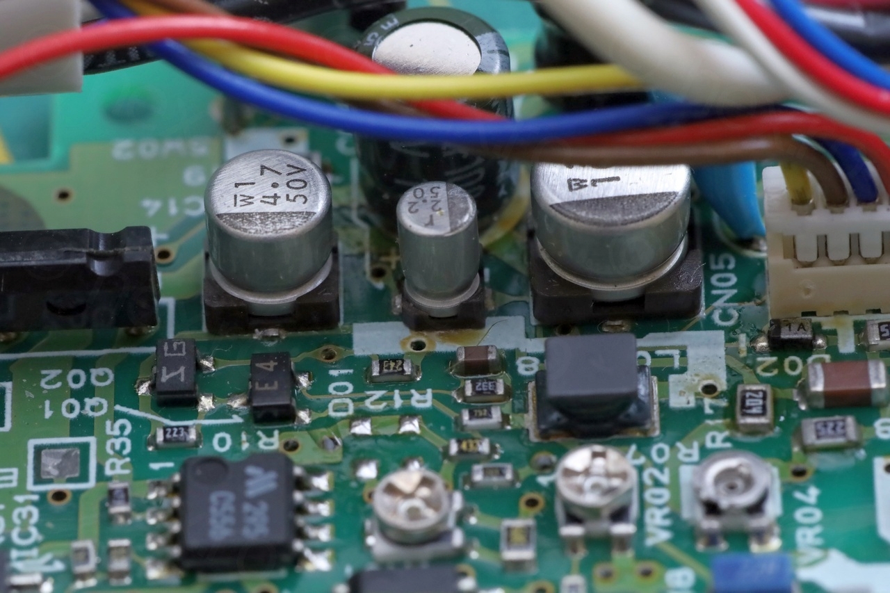
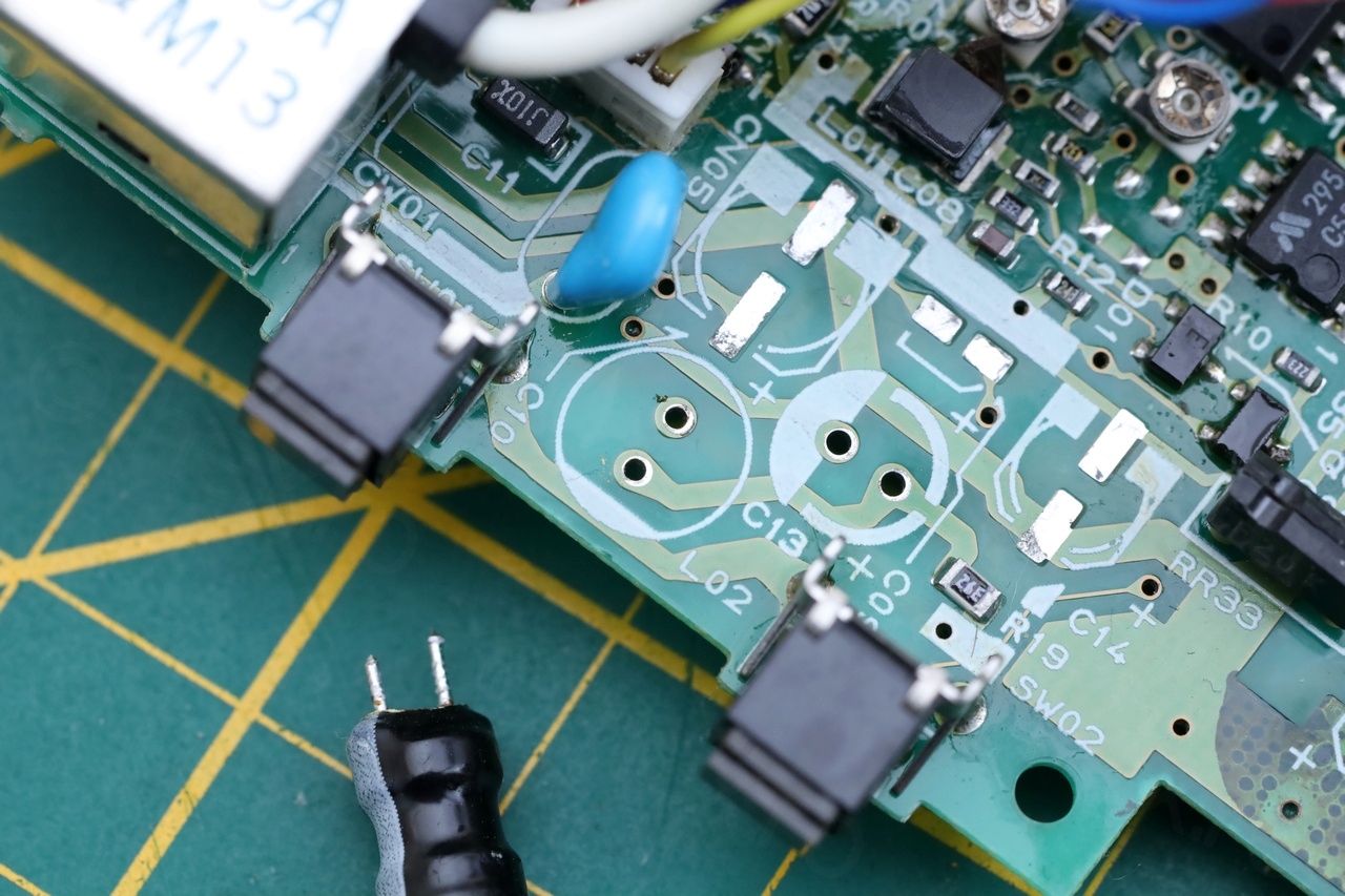
I proceed to dismantle the SMD capacitors, and yucked at what lied underneath:

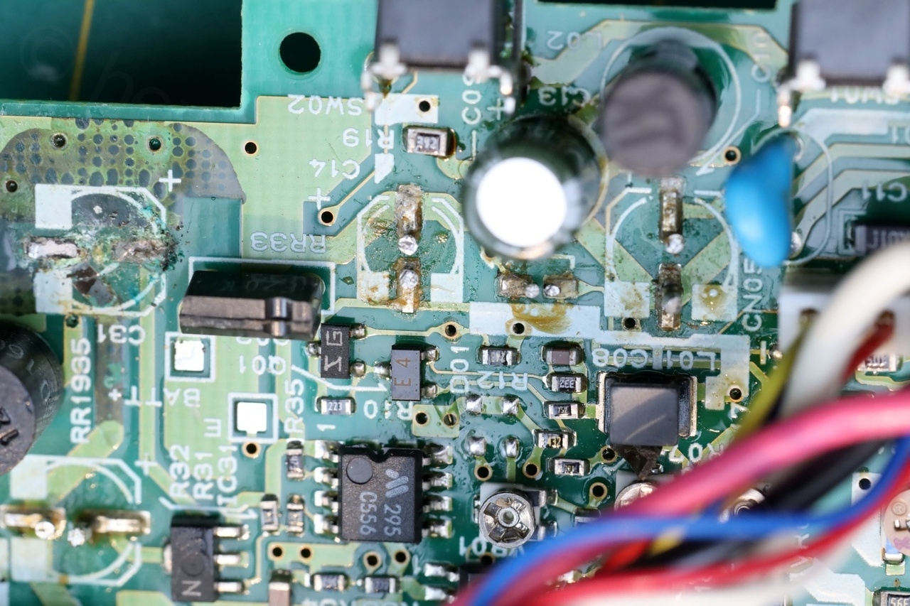
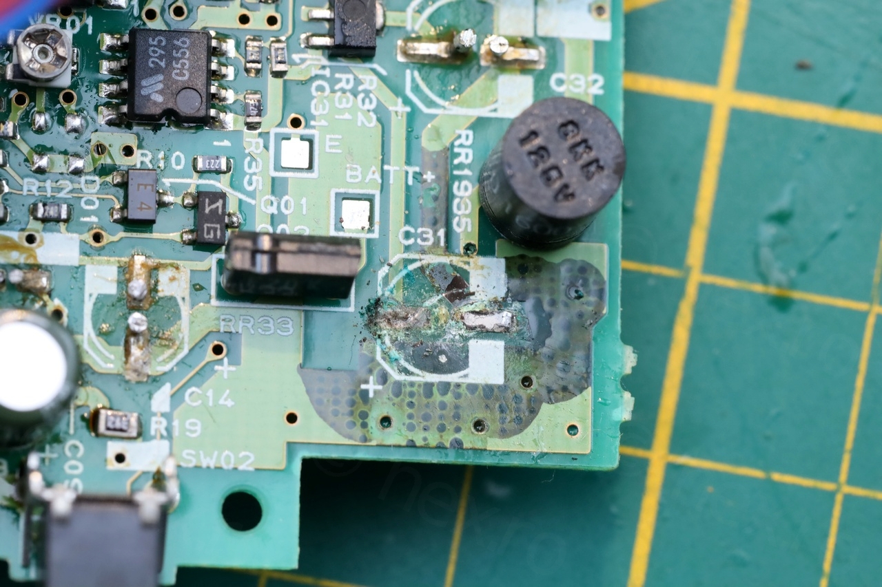
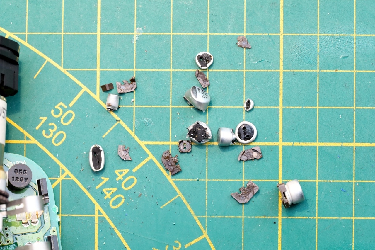
The leak was so badly that it infiltrated the board, and all capacitors had brown deposits underneath. The inductor marked with ‘XT’ needed to be taken out, otherwise impossible (with my tools) to reach and de-solder few of the caps that were bunched together.
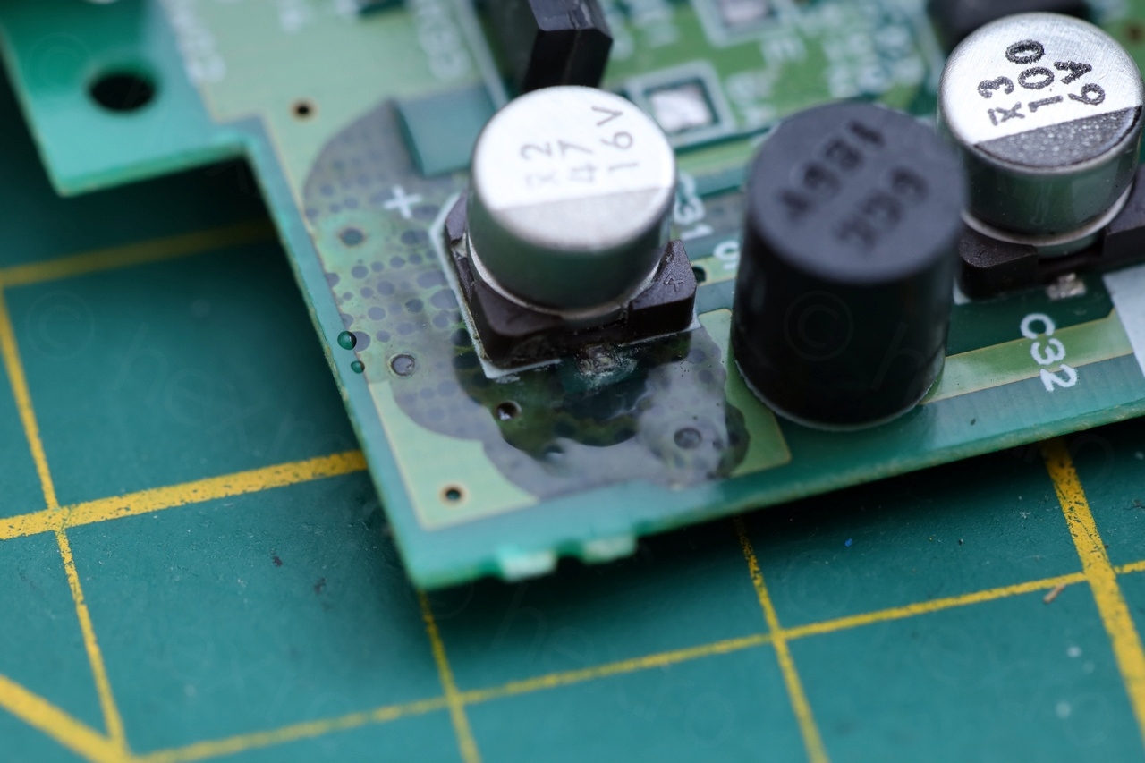
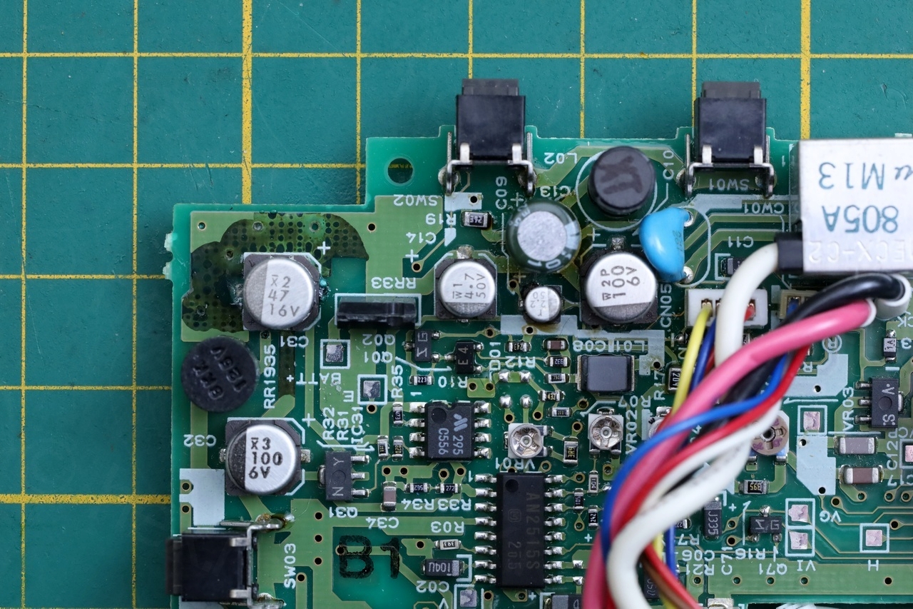
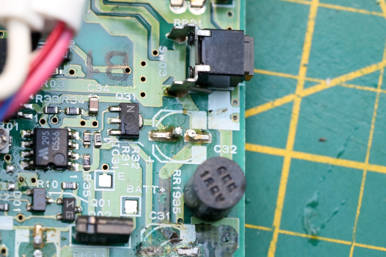
Cleanup
Cleanup was easy, but unfortunately, one track almost got cut.
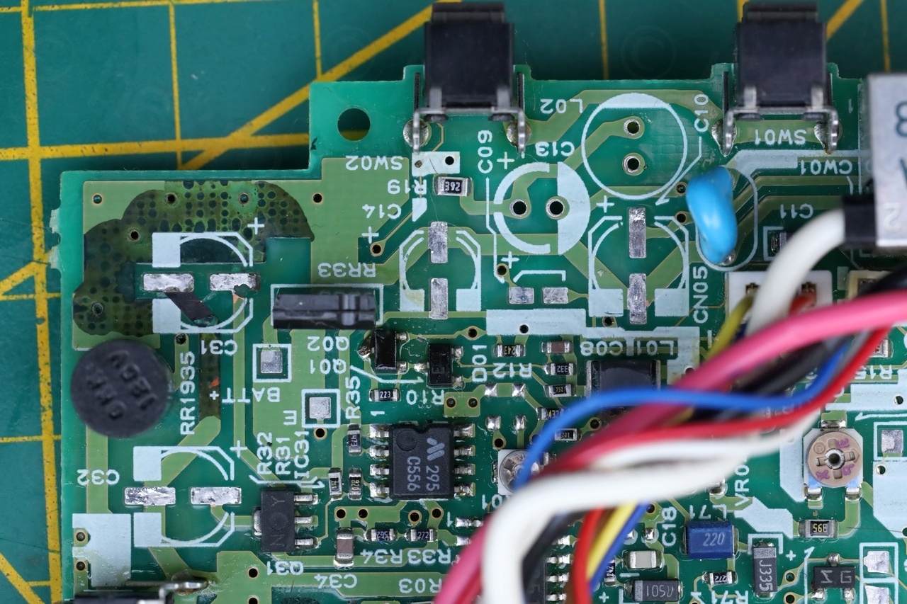
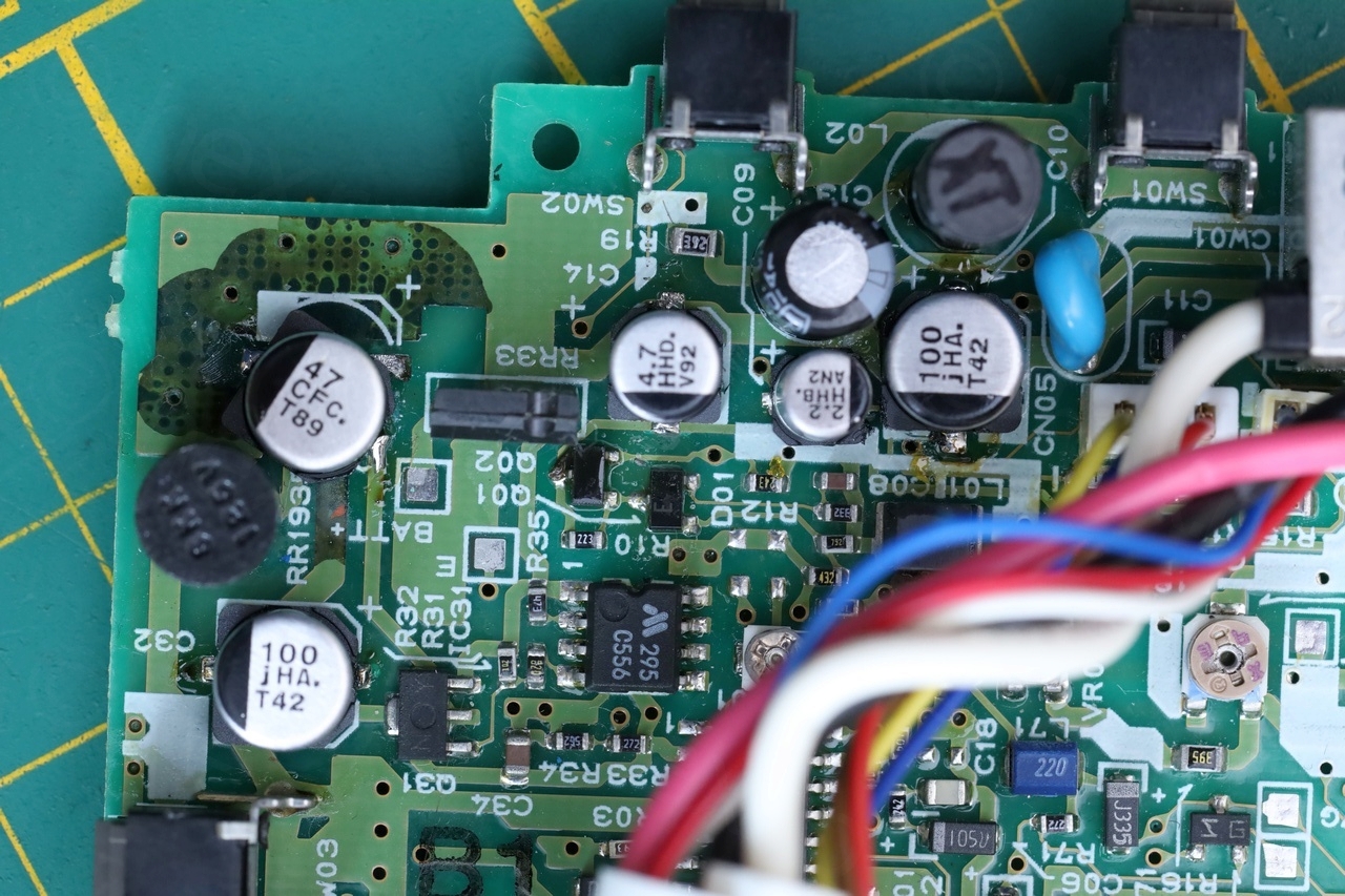
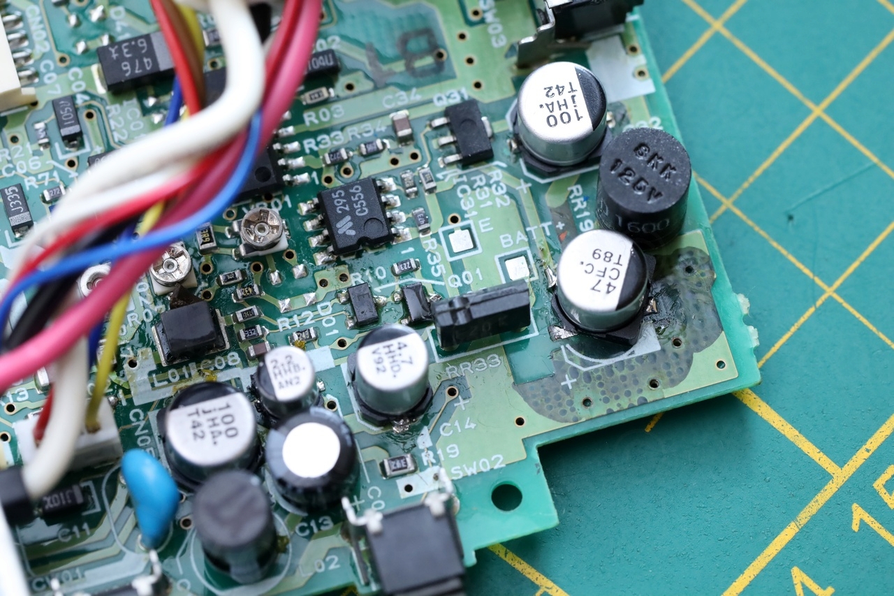
At least this Canon was using the exact same capacitors that many other cameras do. I had all the capacitors already 🙂
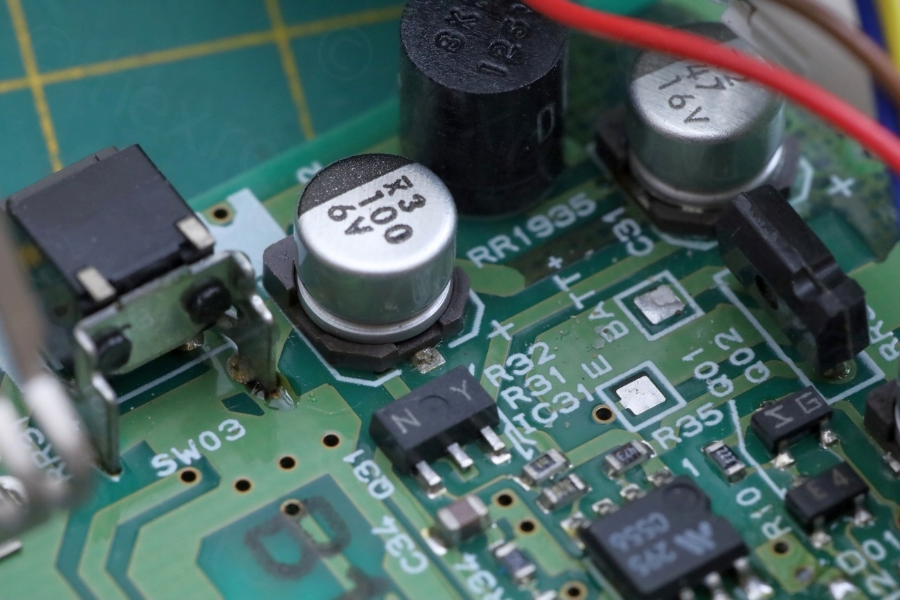
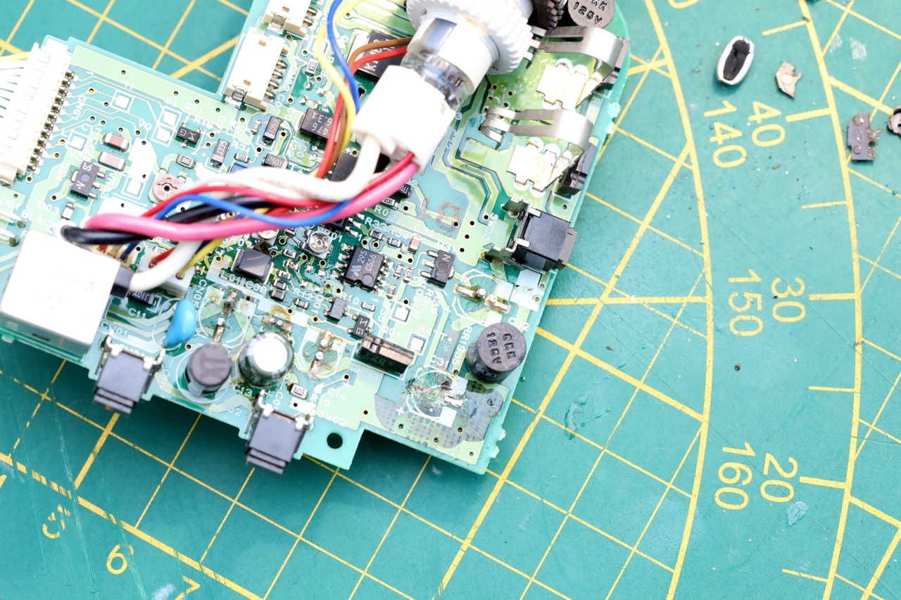
Soldering new capacitors
For the one where the track almost got interrupted, I just soldered the capacitor at an angle. I don’t really want to collect these boards, but just to get them to the state where I can see an image on the CRT.

Powering on the EVF unit
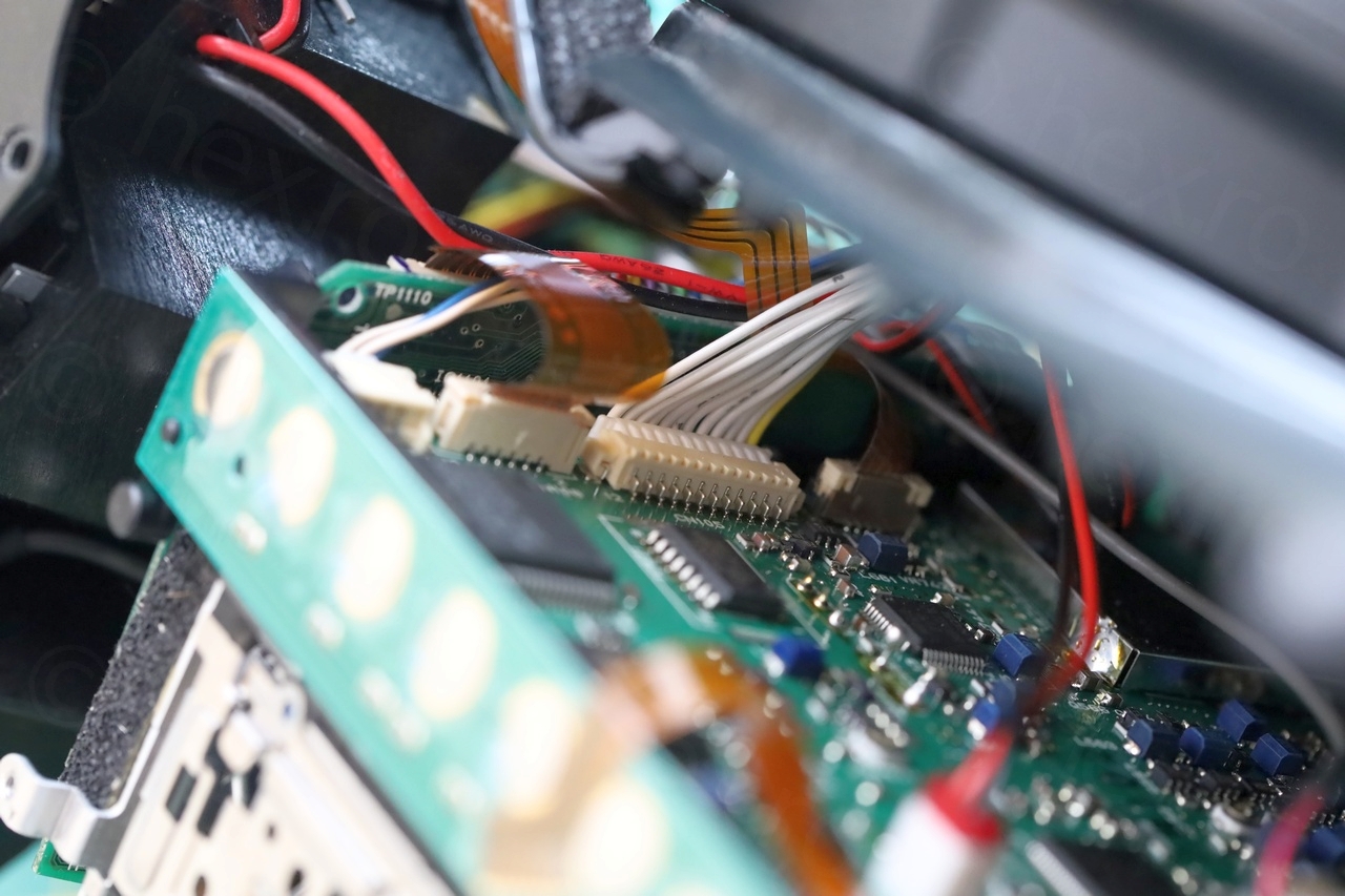
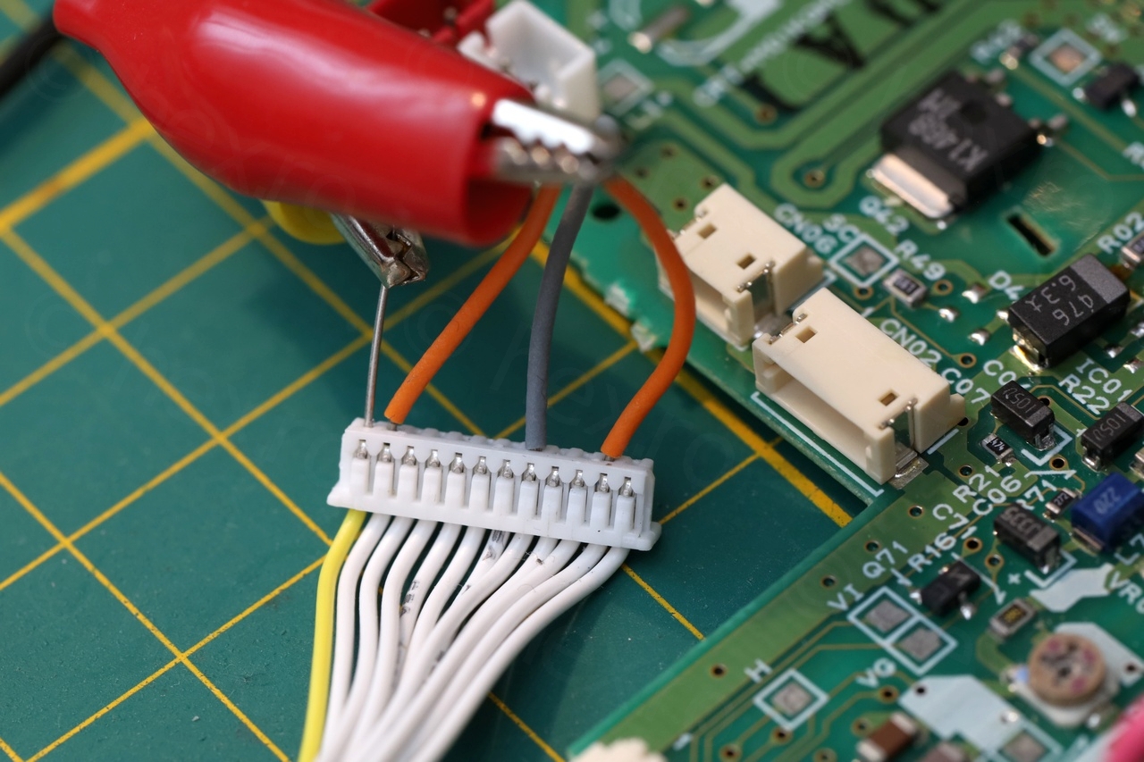
Finding the correct way to power on the EVF was a tricky. Initially, I hoped it would be similar to the Canon E60E camera – but on a close inspection, I was not lucky, the E60 camera has 11 pin connector, this one has 12, so … which one will it be ?
Tracking down the “EVF ON” pin
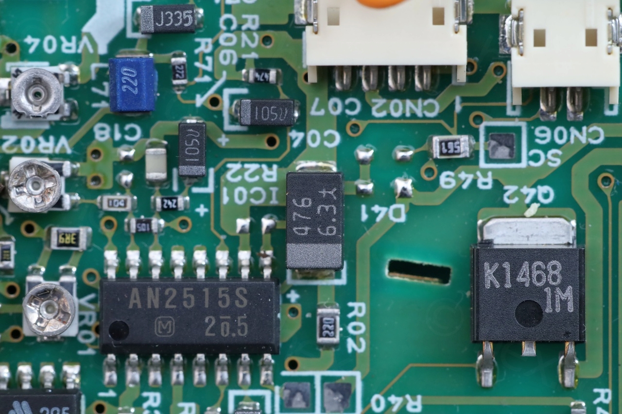
On Canon E60, there is a pin that has to be hooked to GND, otherwise the EVF Unit will not power up. Looking more carefully at that schematic, I tracked the “EVF ON” signal going to a voltage regulator which was labeled LVC556 … Hmmm what if ? … Surprise surprise. I found the same 556 IC on this E300E camera 🙂
I was able to track its PIN 2 to one of the wires of the long 12 pin connector – that pin should be connected to GND, otherwise this 5V Regulator will not provide power to the circuit.
However, all was not fine yet.
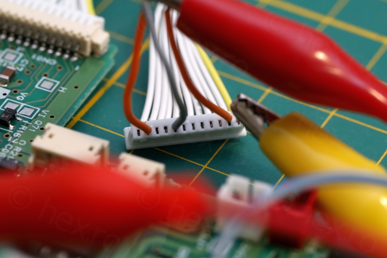
Mystery pin
Upon powering up again, the mini CRT was alive – I heard the Fly Back Transformer starting up and the CRT lit. Found also the Video IN signal after trial and error (more on it further down).
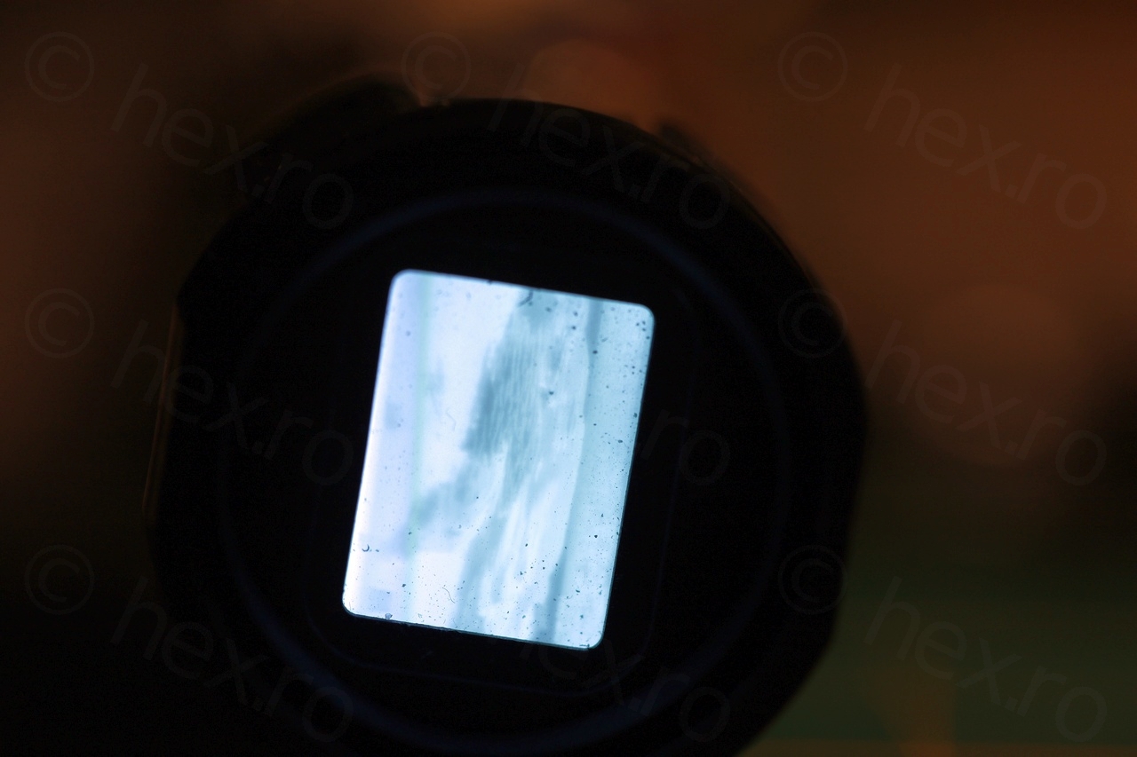
However, the CRT did not display the image coming from the Raspberry PI, but a blurry mess with black bar at the bottom:
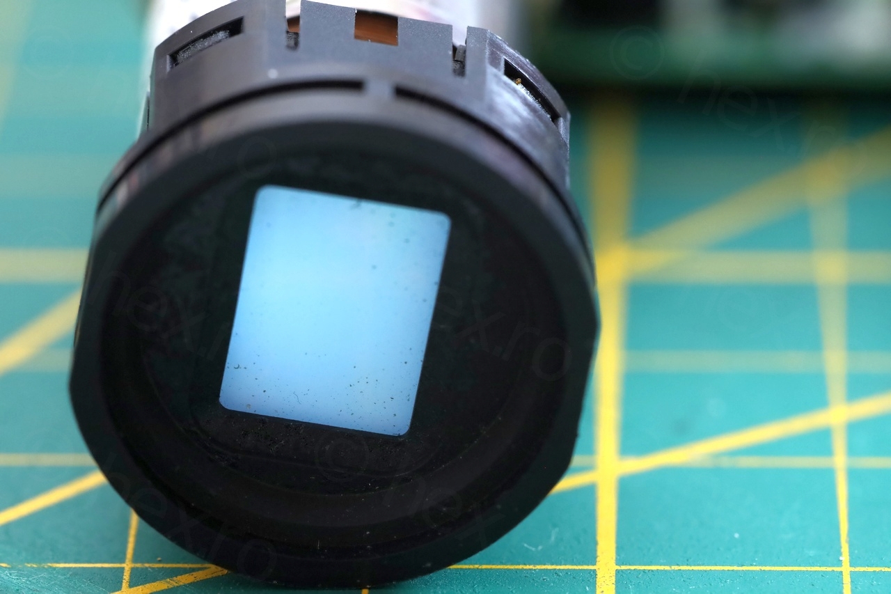
Without a Video IN signal, the CRT was lit evenly, but when it was supposed to show an image, the top part of the CRT was white, with a black bar at the bottom.
This was also very annoying, one more trap with this type of Canon cameras. I was at a loss why it would not work. Out of desperation, I downloaded the AN2515S schematic and saw its Pin 11 was the Video IN Signal. Change of plans that is, found also the small capacitor that is hooked to Pin 11 – and surprise, applying the composite Video IN to the other side of the small SMD capacitor made the image appear!
A little bit further up, the capacitor seems hooked to an SMD transistor ? and this transistor has the two other legs connected to the long 12 pin EVF unit connector. One is what I found as Video IN for trial and error (since applying a composite signal, no other pin made the CRT react). But what about the other pin ? Well, out of curiosity, I hooked this 3rd leg of the transistor to GND and surprise, now it was finally passing the image to the CRT as intended.
Review of signal pins
In total, 5 connections are needed. The VCC and GND go to the big battery pins on the EVF viewfinder unit, 1 pin on the 12 pin connector is the Video IN, and two more pins have to be connected to GND (one to turn on the 5V regulator, second one to enable the pass-through of the Video Signal ?)
Voltage levels
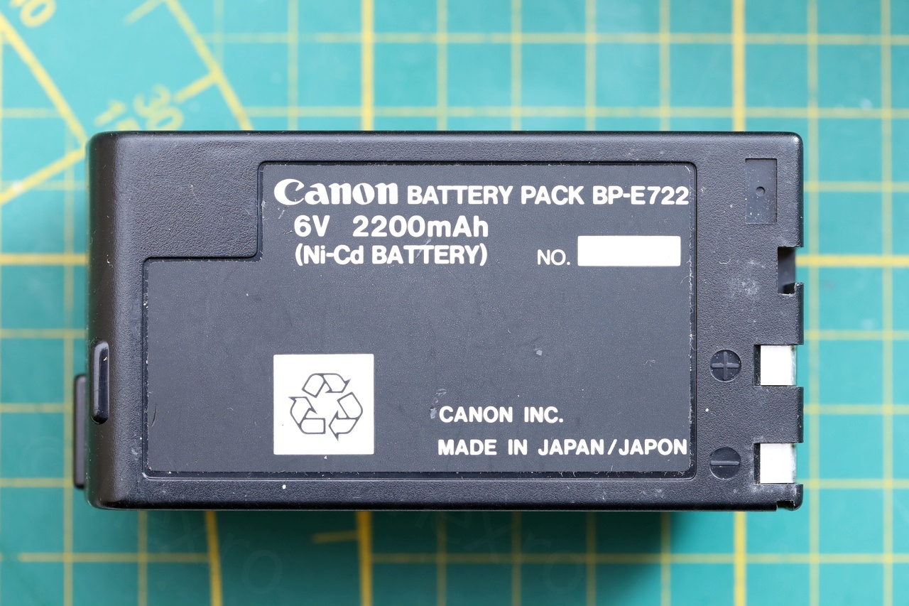
Since there is a 5V regulator on board, and the camera battery is rated at 6V, I powered the EVF unit with 6V from my mini power supply.
As it starts up, it draws about 130mA – CRT appears washed out and bright. After the warm-up (about 1 minute), the consumption drops to around 100mA:

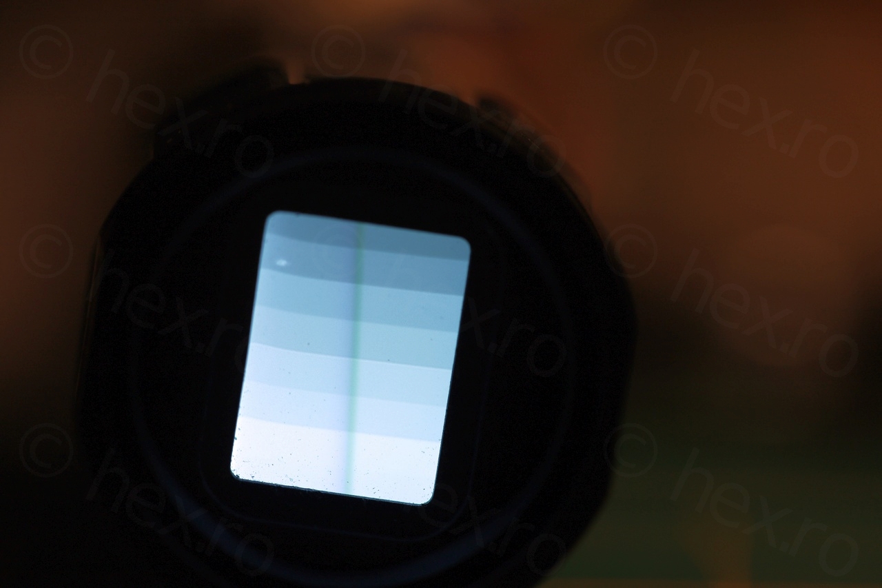
Brightness control
One more problem – but of course – is that the Brightness control does not work. On the Canon E60 camera, the Brightness control did not work either at first, but after washing it with IPA it started to finally work.
On this board though, impossible. I tried but no amount of IPA seems to fix it. Or maybe the problem is somewhere else and not due to the electrolyte from the leaked capacitors. I suspected another tantalum capacitor that I found on the board, but it was not that one – it measured fine after de-soldering, and a temporary one did not improve the situation.
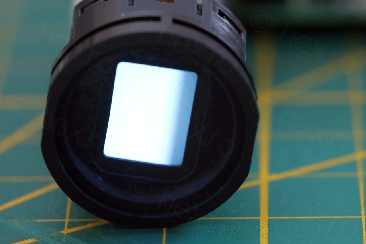
The image is very bright and thus very soft:

I gave up trying to fix the driver board. Maybe I could have went a little further, since at least I have the manual of a similar looking board. Maybe I could have de-soldered more components, to measure them. But I am not expert on CRTs and how to drive them. With the high voltages around, I preferred to stay away. The CRT is alive and the board is acceptable enough to prove it.
Leave a Reply