


Introduction
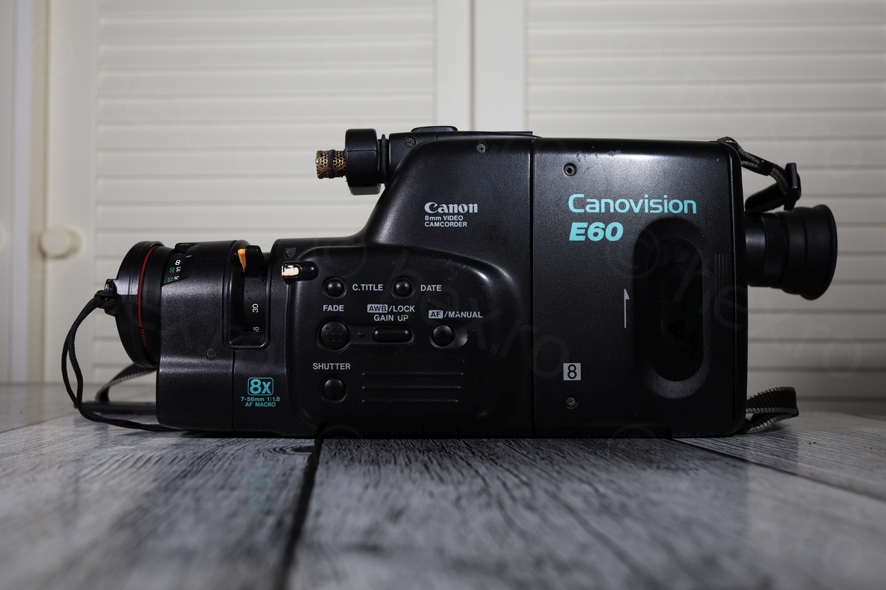
I found this mini CRT into a Canon Canovision E60E 8mm camcorder. It was tedious to get it to work due to multiple issues on the driver board: all capacitors were leaky (and either open or very high ESR), some cold solder joints of the Flyback Transformer and finicky brightness potentiometer.
Camera overview and tear-down
There will be many photos below, from dismantling the camera, diagnosing the issues with the driver board and the fixes and the results at the end.
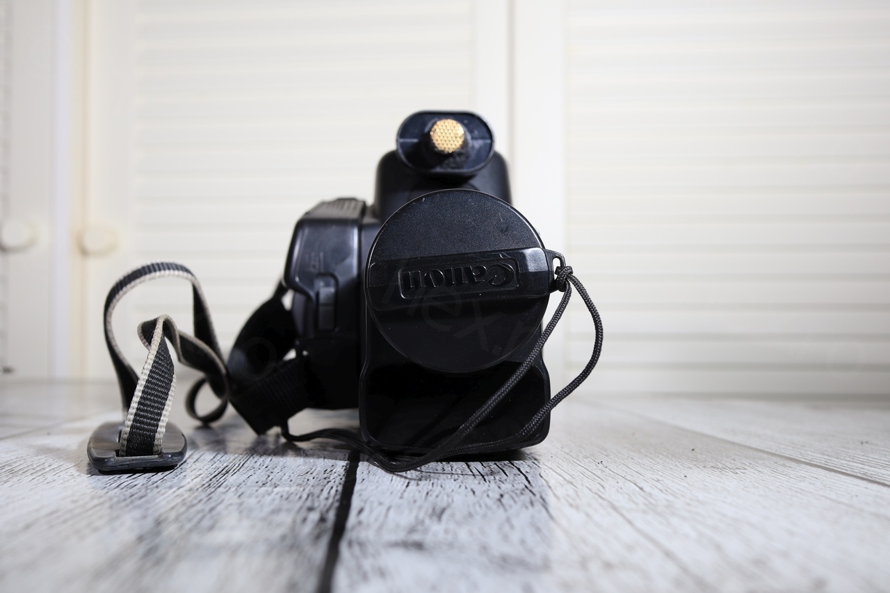
This is how the camera was sold:


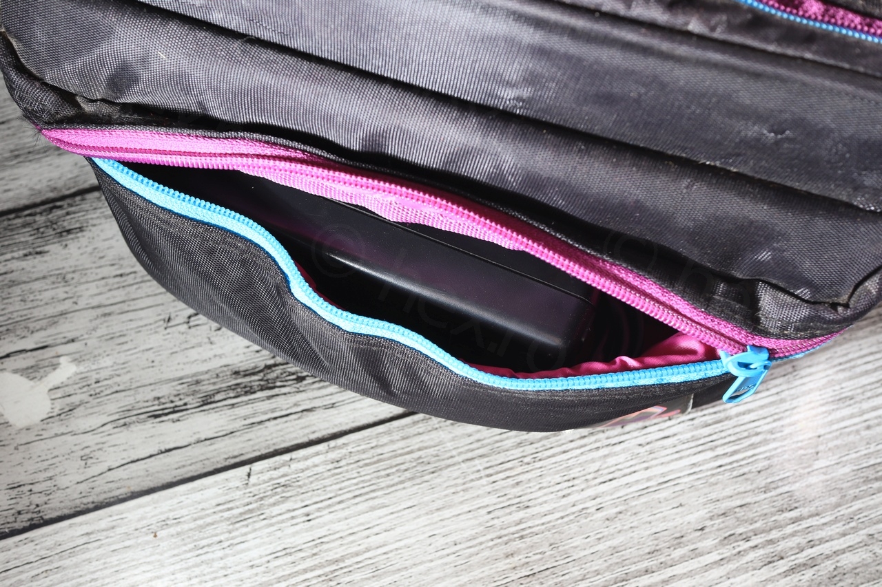
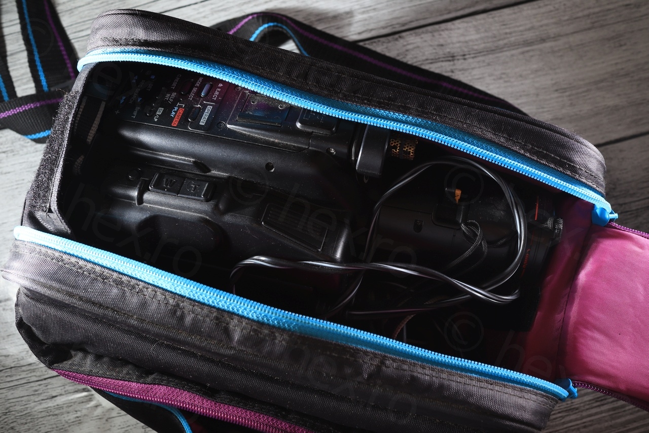
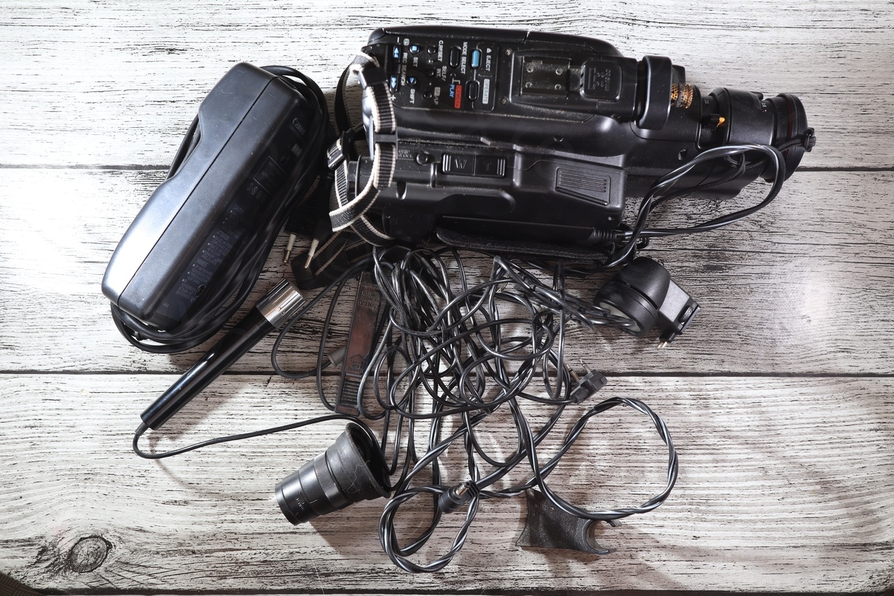
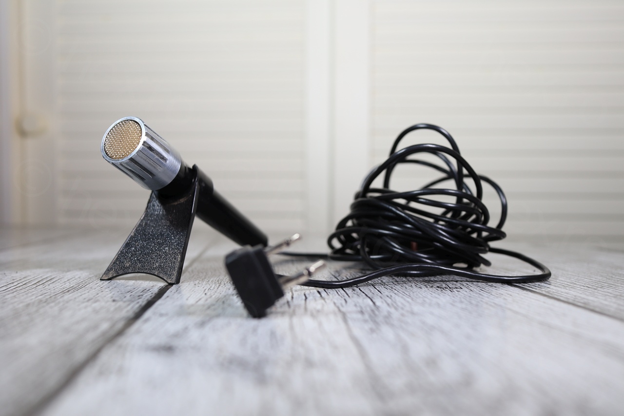
Surprisingly, the carrying bag reserved few surprises, especially, the Canon VL-7 Video Light, a very old Canon Remote Switch and a Canon DM 30R microphone with its holder (not to mention the power brick).
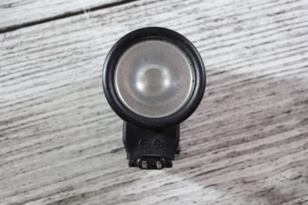
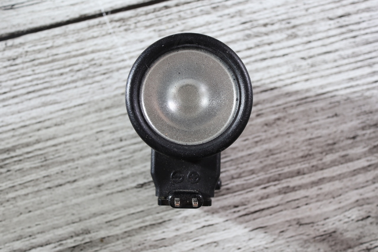
Canon VL-7 – front 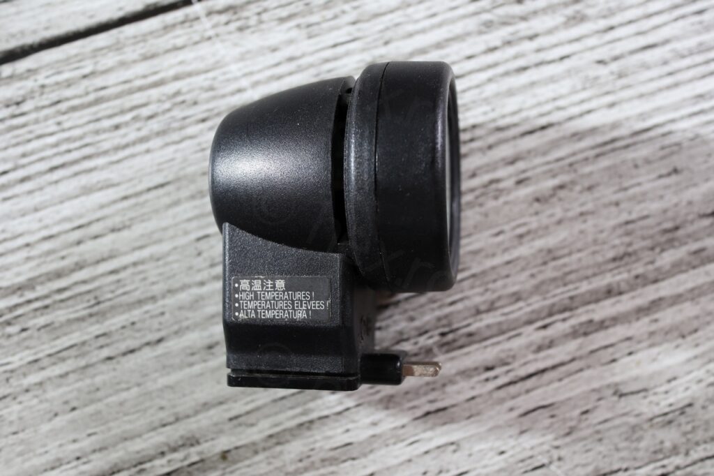
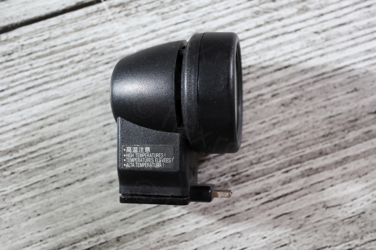
Canon VL-7 – side 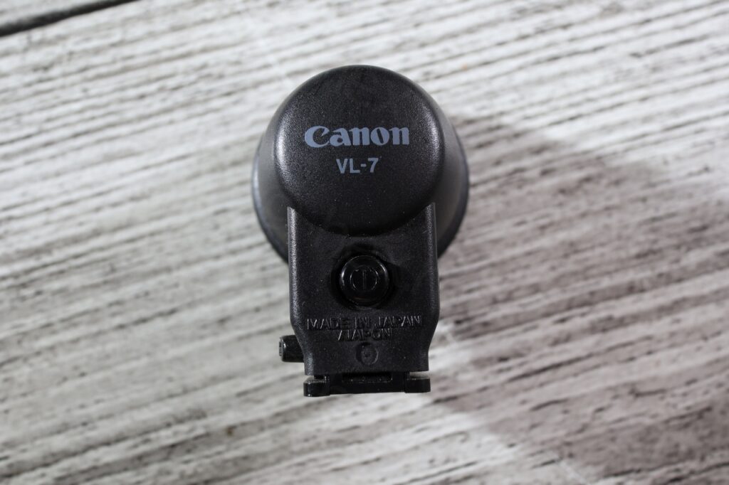
Canon VL-7 – back 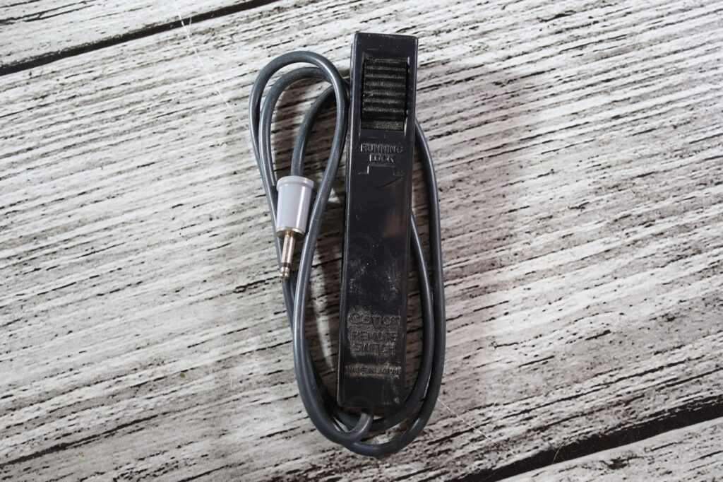
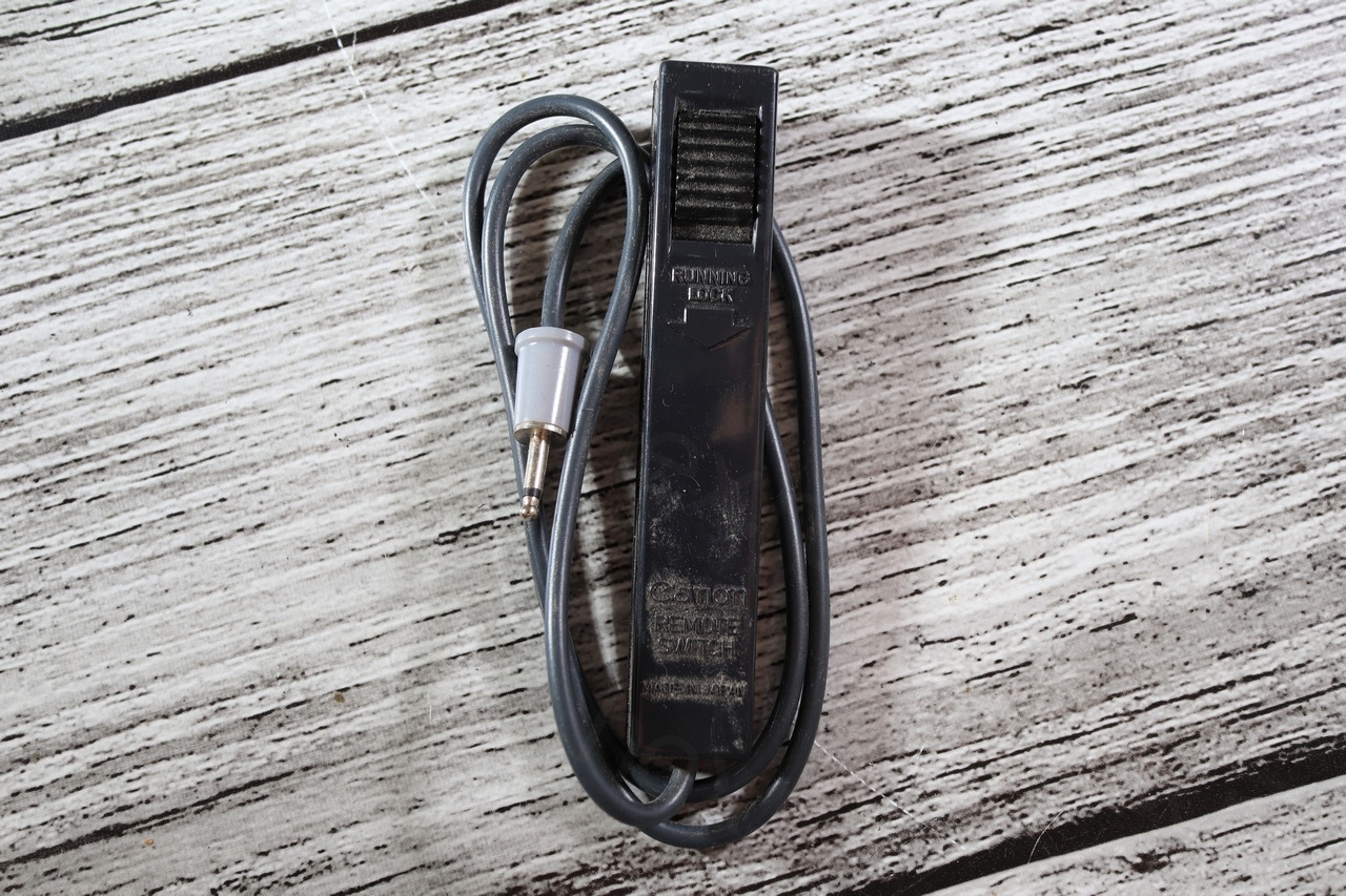
Canon Remote Switch 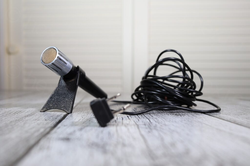
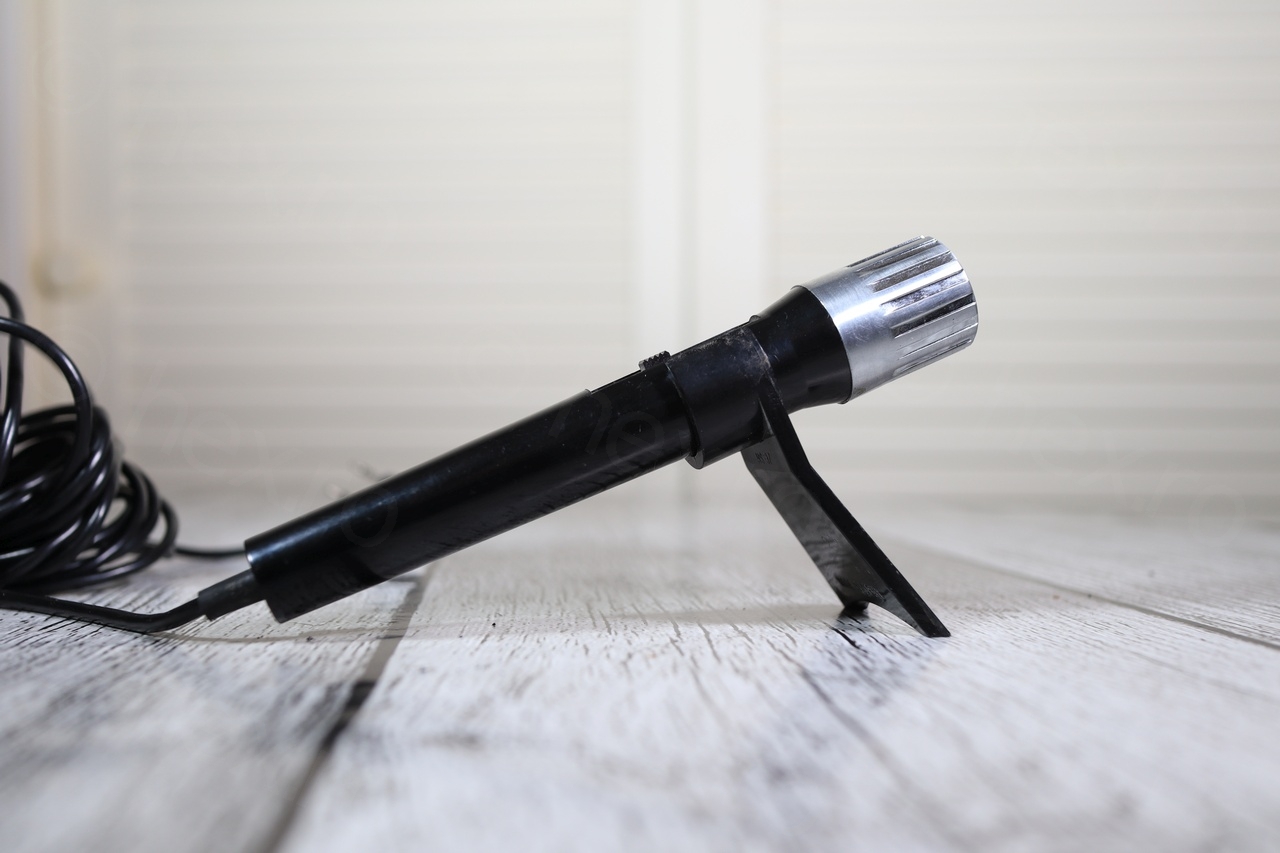
Canon DM 30R 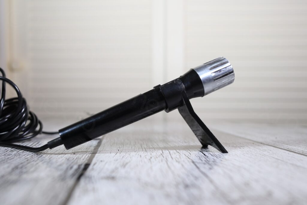
Canon DM 30R – side

Based on the accessories (Light, Microphone, Remote Switch), I figured this camera was more than an amateur camera and was hoping it may be usable. However, first sign of trouble was the camera refusing to start when powered by its own charger. There was no sign of life at all, and while I was hoping that the Electronic View Finder unit would still be usable, it turned out it wasn’t.

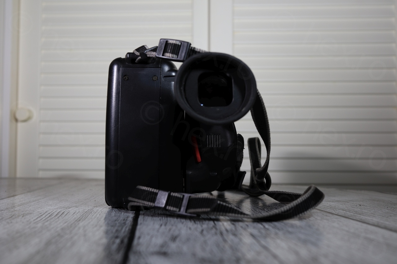
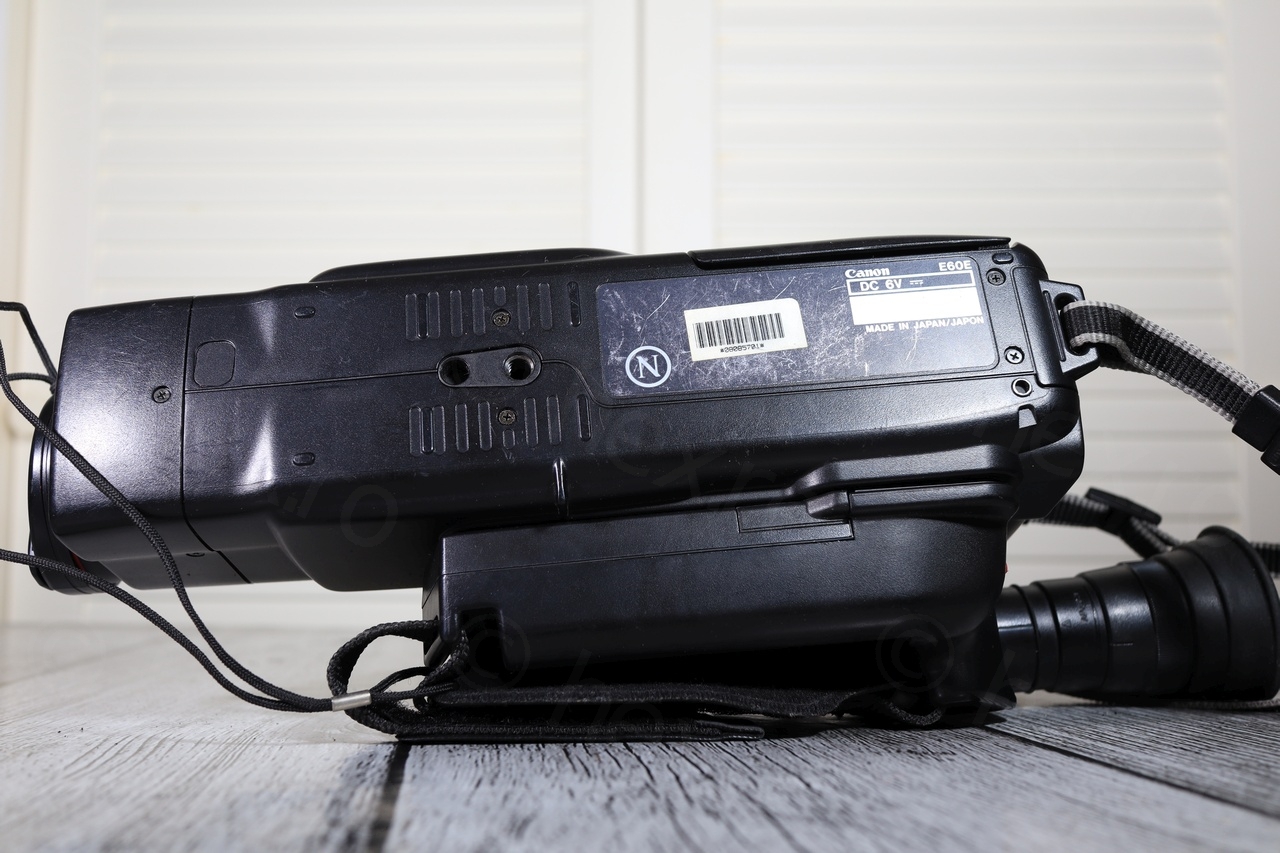
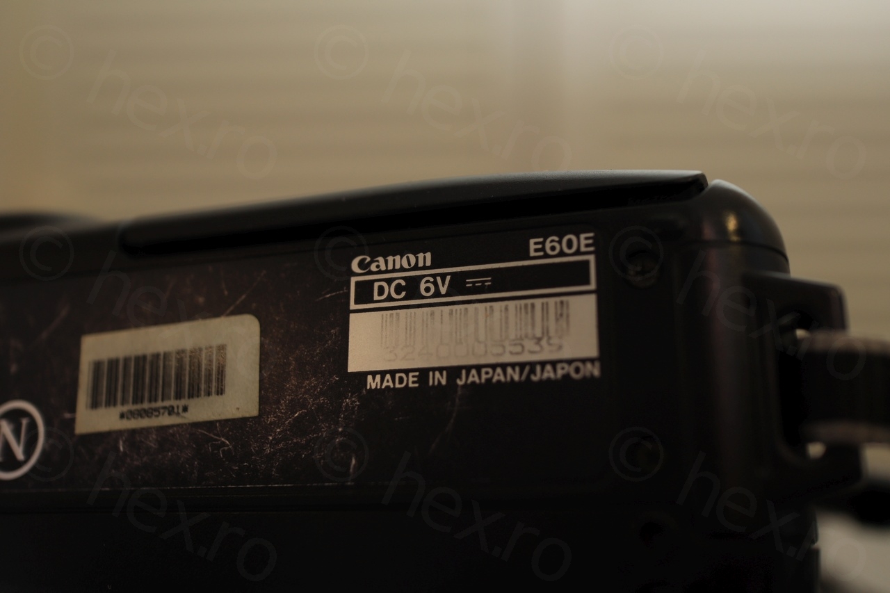
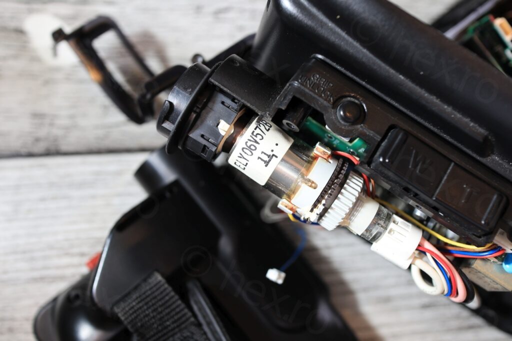
The serial number was hard to read under normal light and it was a little disappointing that the EVF unit was part of the handle itself (not usable for small projects with RaspberrY PI for example).
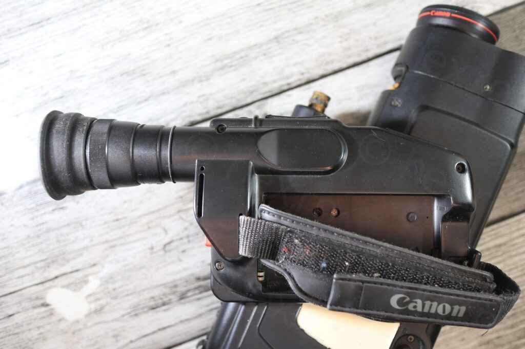
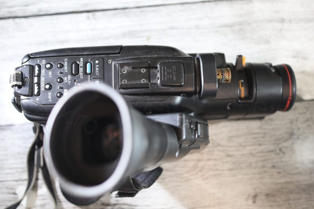
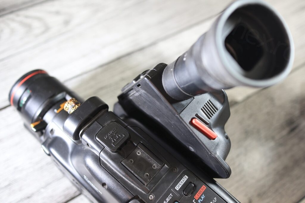
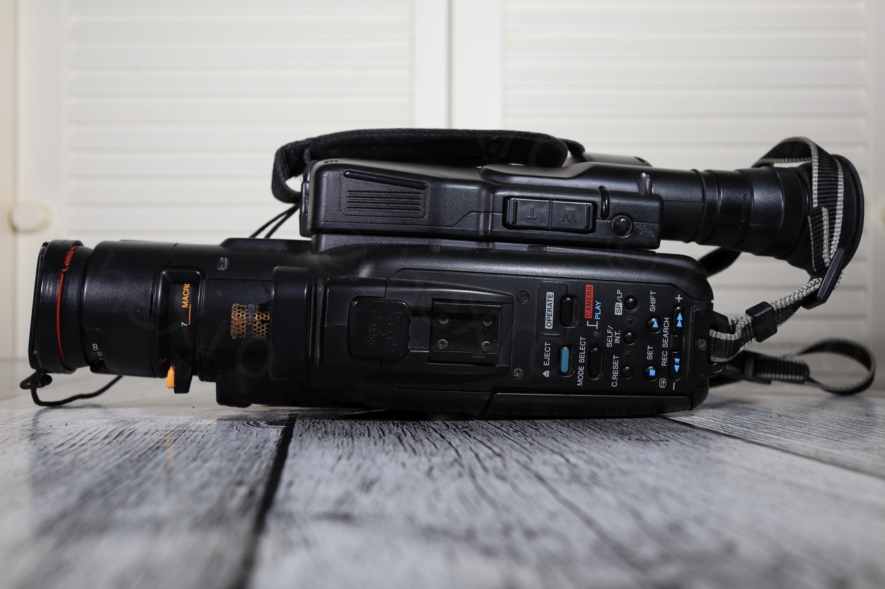
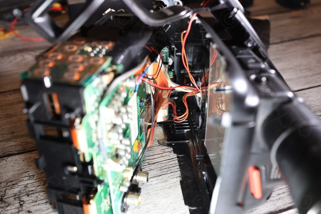
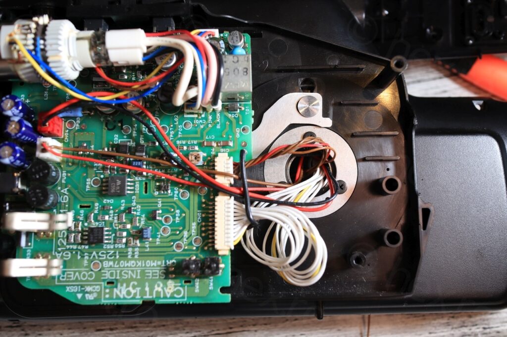
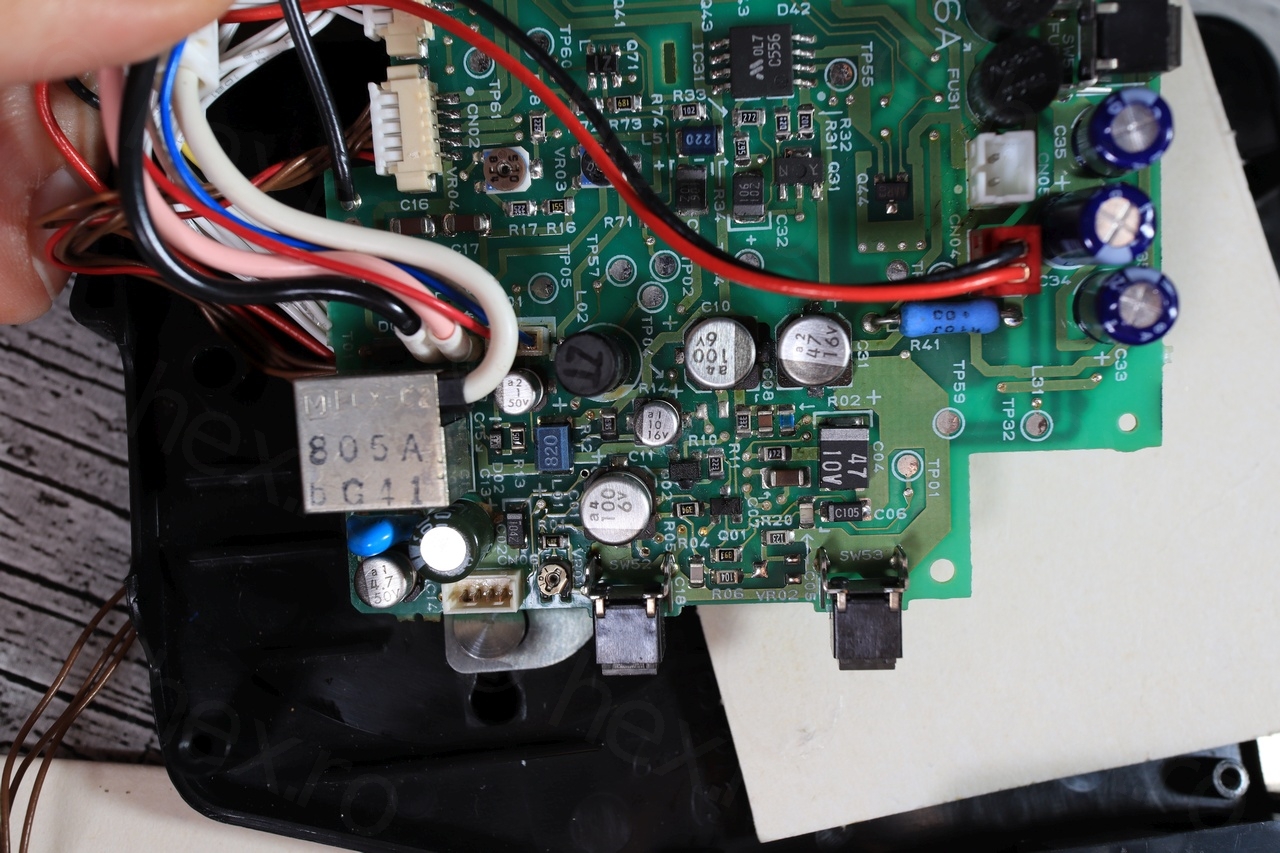
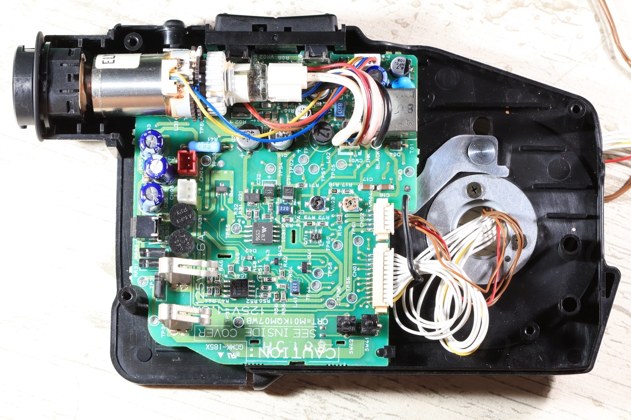
Camera was easy to dismantle (no hidden screws) but the tear-down revealed a ton of wires going from the hand-grip towards the inside of the camera. Not only that, but to detach the grip would require dismantling of the lens assembly too, as some of the many wires were soldered directly behind the lens:
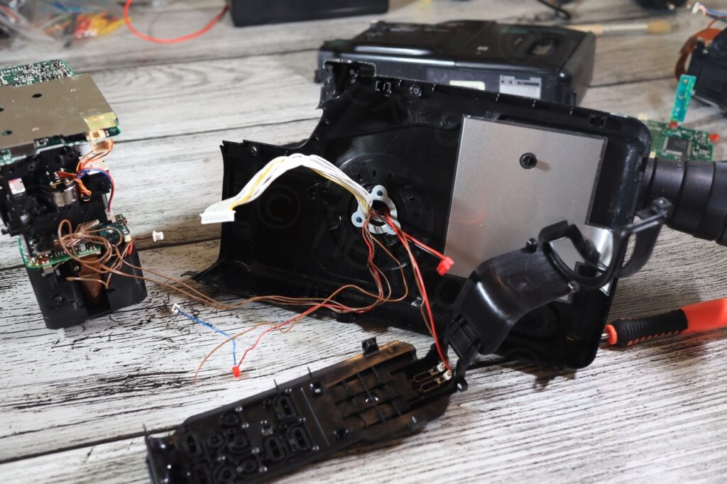

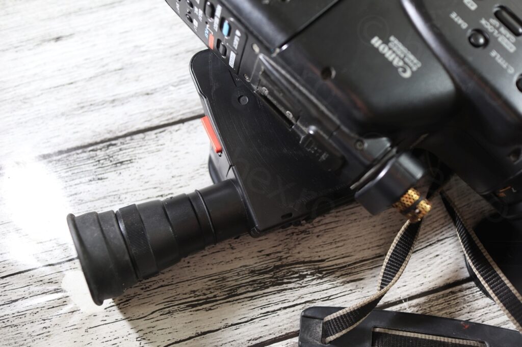
Eventually, I worked my way into the camera and was finally able to detach the hand grip:

Camera was made in Feb/March 1991 according to the date markings I found inside the hand grip plastic case.
mini CRT – issues
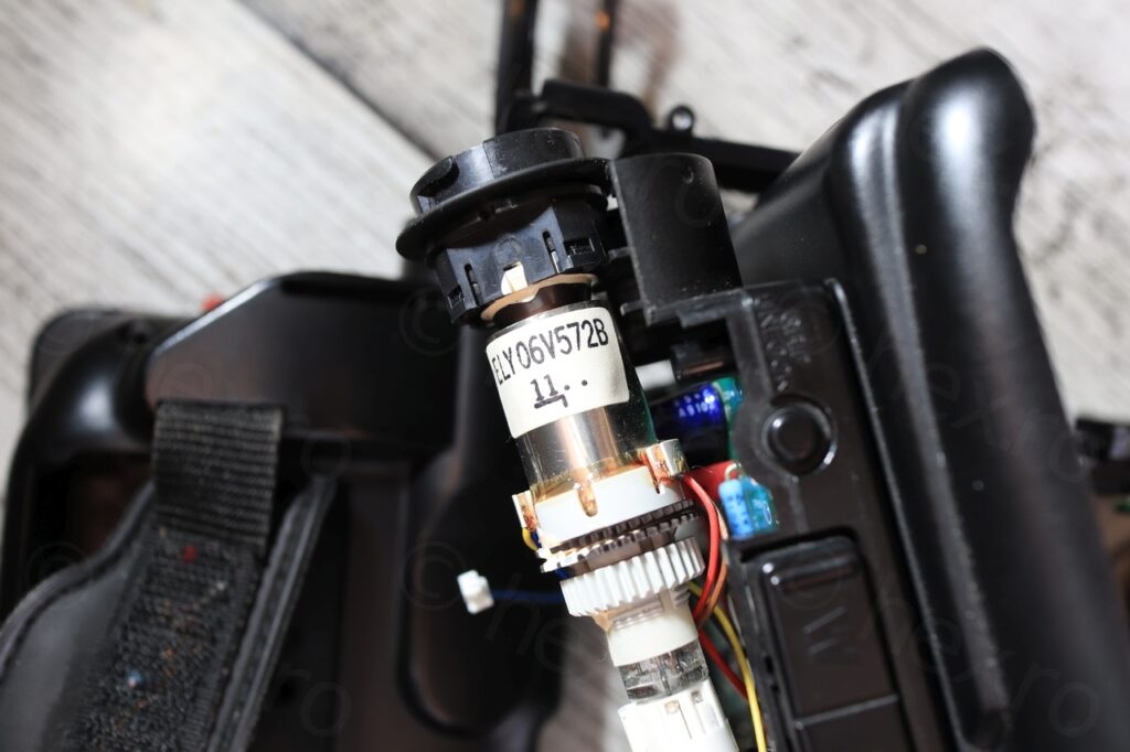
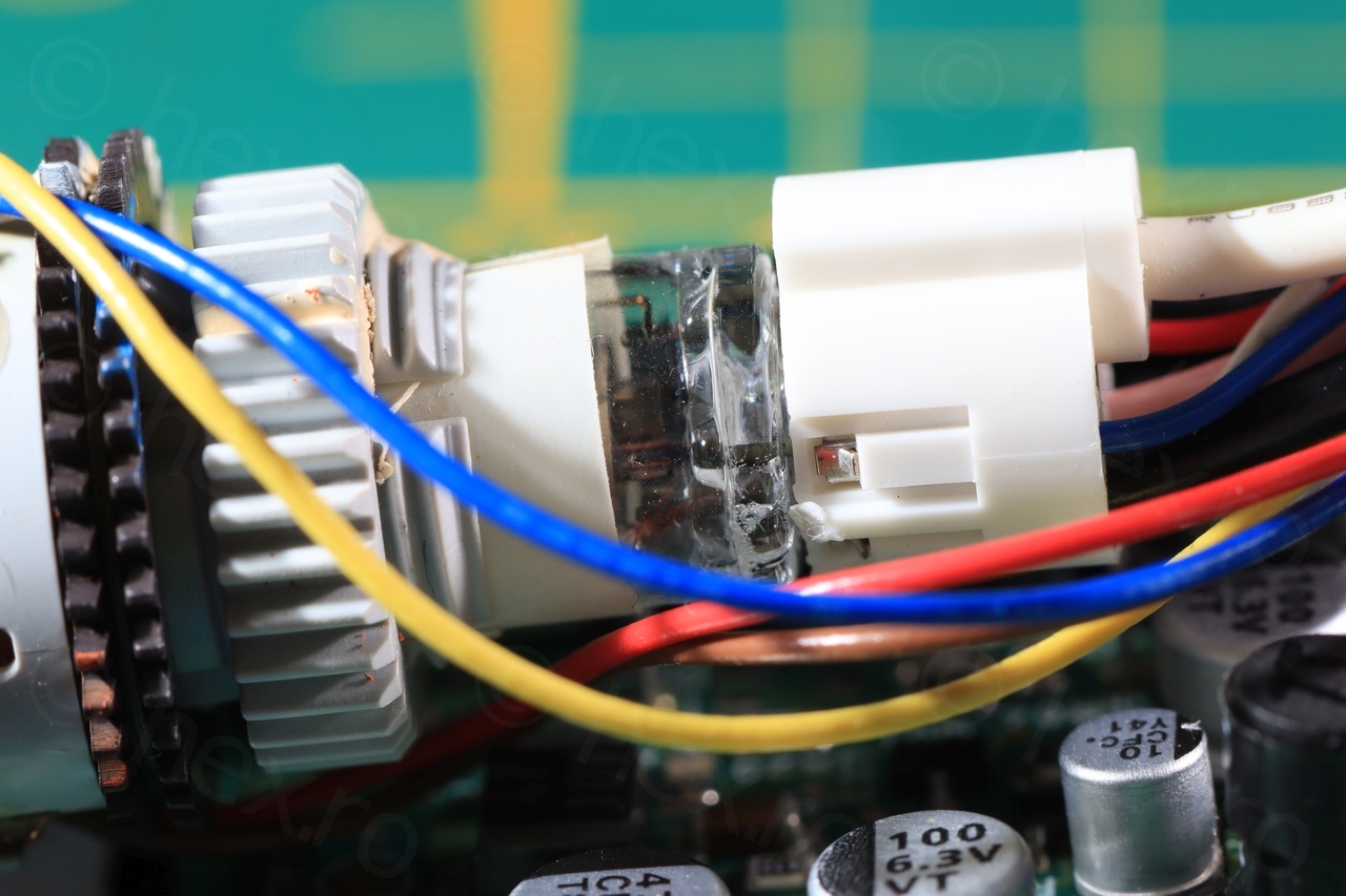
GND is easy to find by trail and error, using a continuity meter from the external case of the Flyback Transformer to any of the wires, but I was not at all able to locate the Vcc using this approach. At least one of the pins of the FBT has to be connected to Vcc, but for this camera, I was not able to find the connection between FBT and the + power traces on the Power/Driver Board.
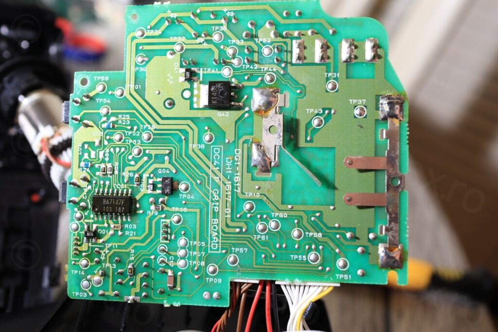
The EVF driver board uses a BA7147F chip (which seems an older version of BA7149F that I find in many newer other cameras) – but no schematics are to be found online …
After these setbacks, I started looking to see if there are maybe schematics available for the E60. Found one here, and wow, having the schematic is extremely useful. It contains detailed connection / block diagram for the BA7147F chip! On closer investigation, the mystery of missing VCC is explained. There is an EVF ON (active low) signal that is supposed to power on a 5V regulator that in turn would power on the whole EVF unit! Bingo.
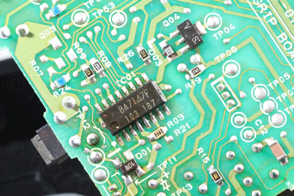
BA7147F 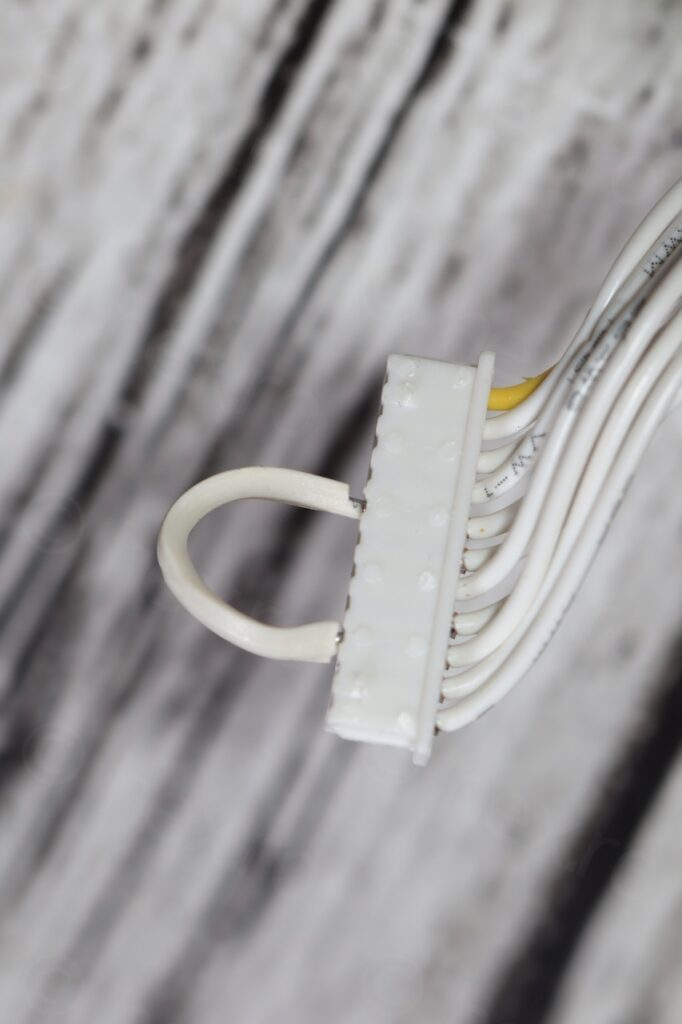
EVF ON (active low) connected to GND
With the EVF ON signal connected to GND, Vcc started appearing on the board and BA7147F was receiving it. However, no sign of life from the mini CRT, and no high voltage present on the FBT pins. Something was terribly wrong.
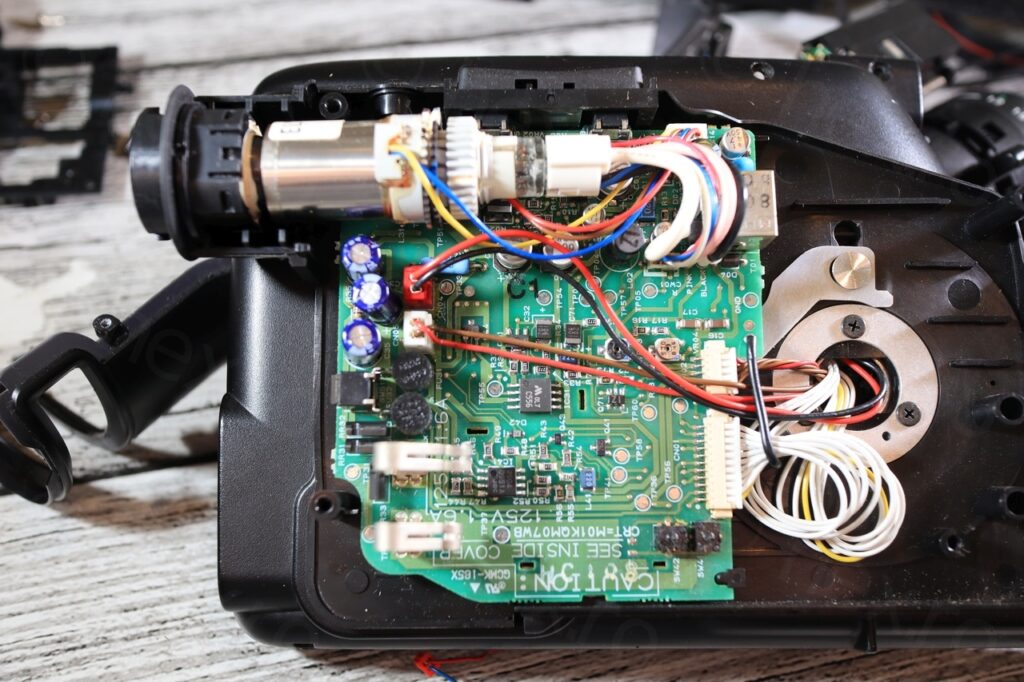
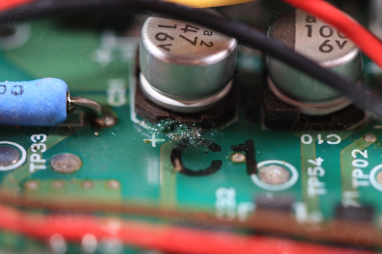
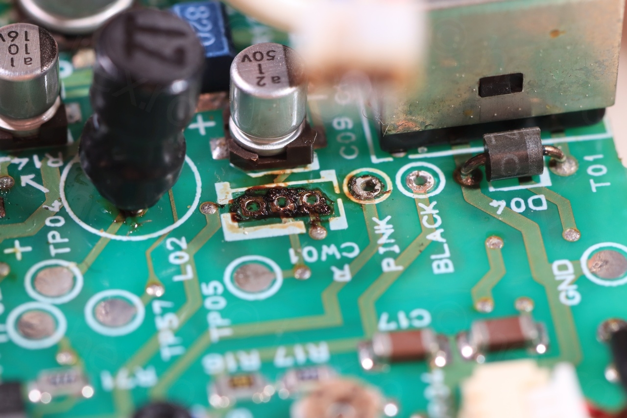
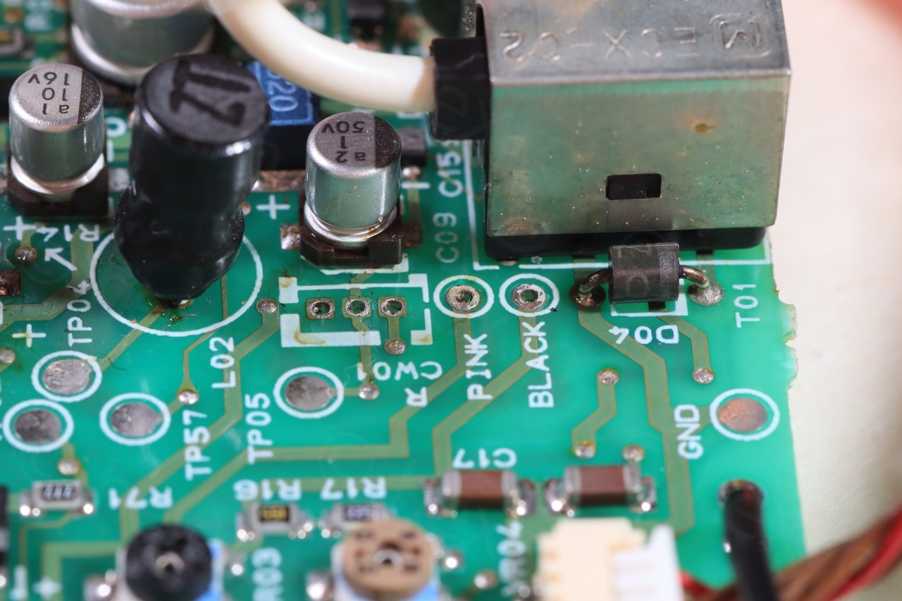
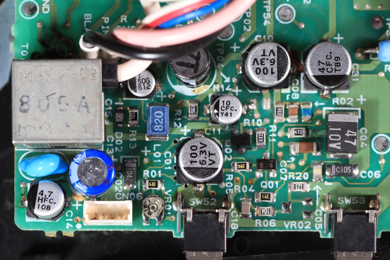
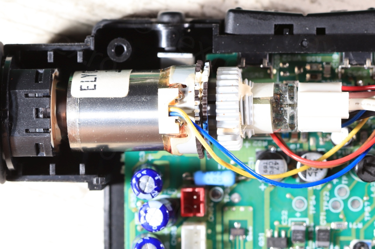
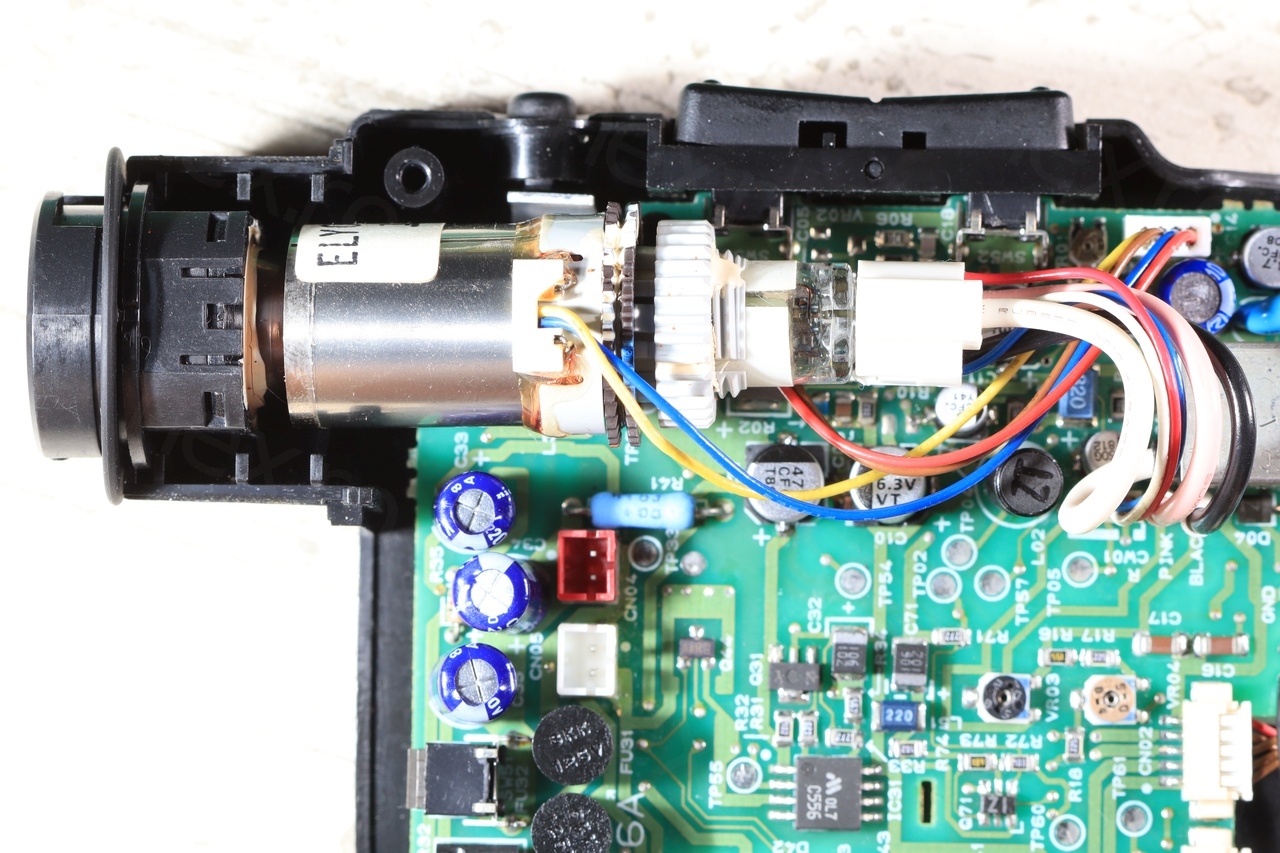
Having inspected the board though, I could tell something was off with the electrolytic capacitors, 7 in total:
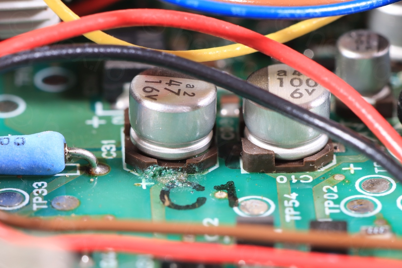
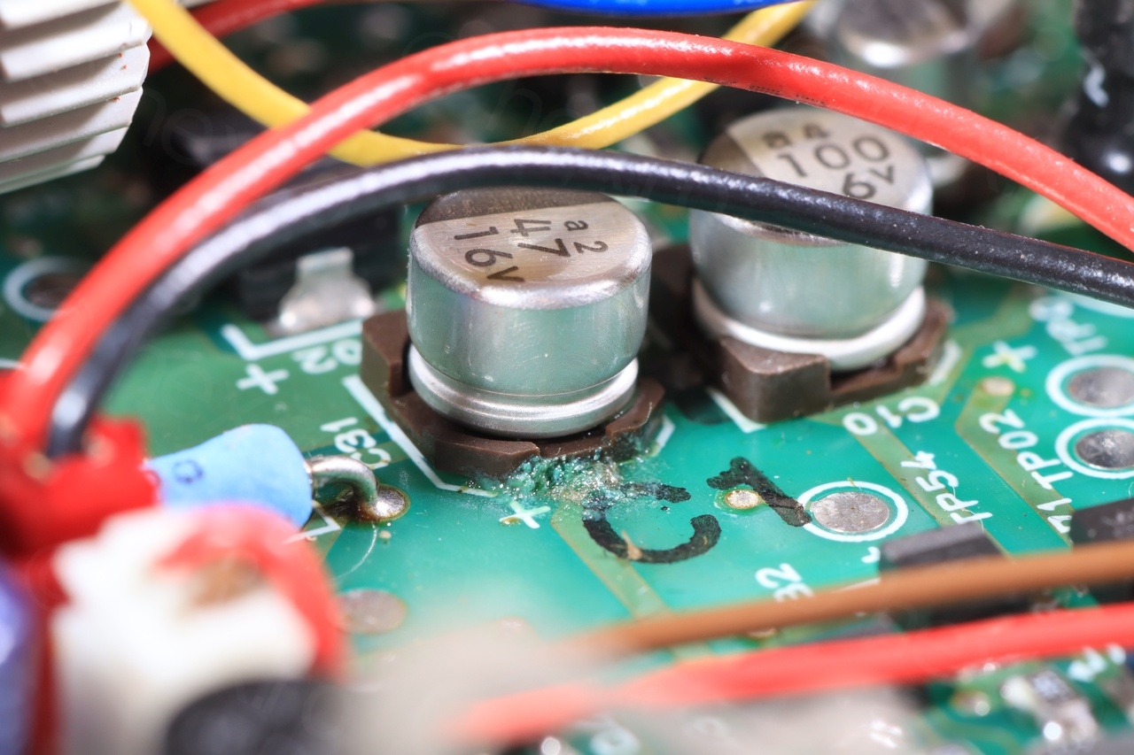
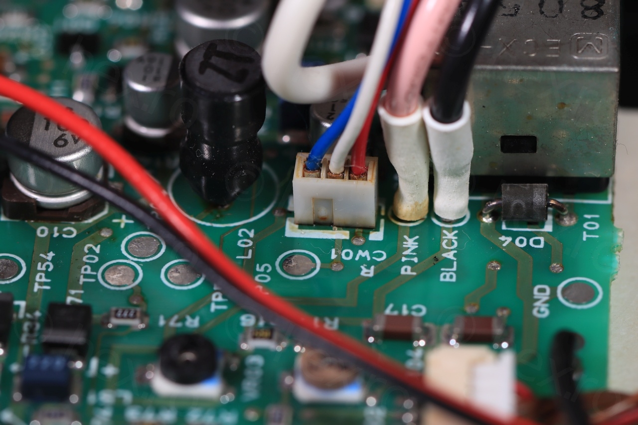
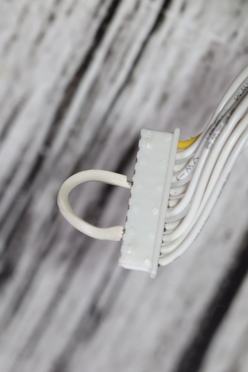
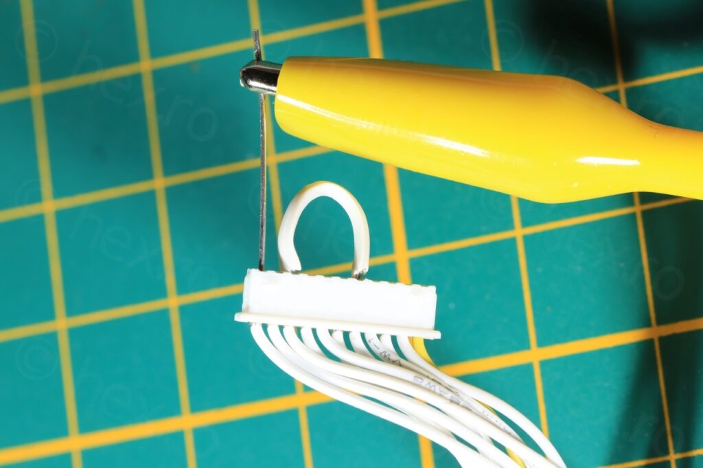
Since there were 7 capacitors on the side of the driver board, I have decided to replace them all. De-soldering them was difficult due to the positioning, and I had to de-solder also the wires going to the mini CRT directly, to get access to a small cap which was just behind them.


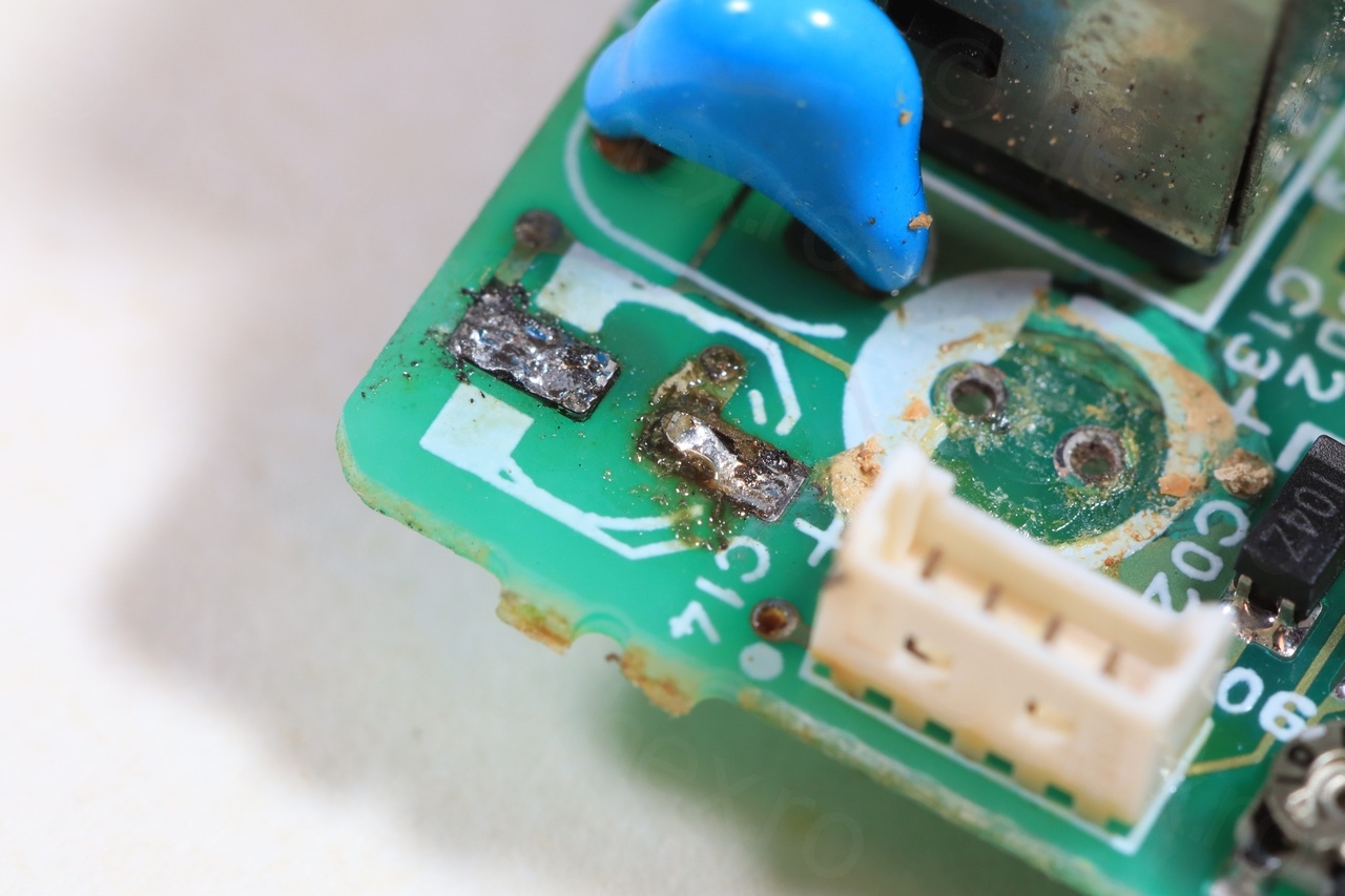
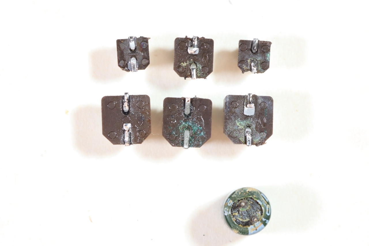
I wanted to measure the capacitors, thus, I did not use the twisting method to take them off the board. And due to lack of a thin soldering iron, there was a little bit of damage to some of the pads which detached, but not to the point where they broke off:

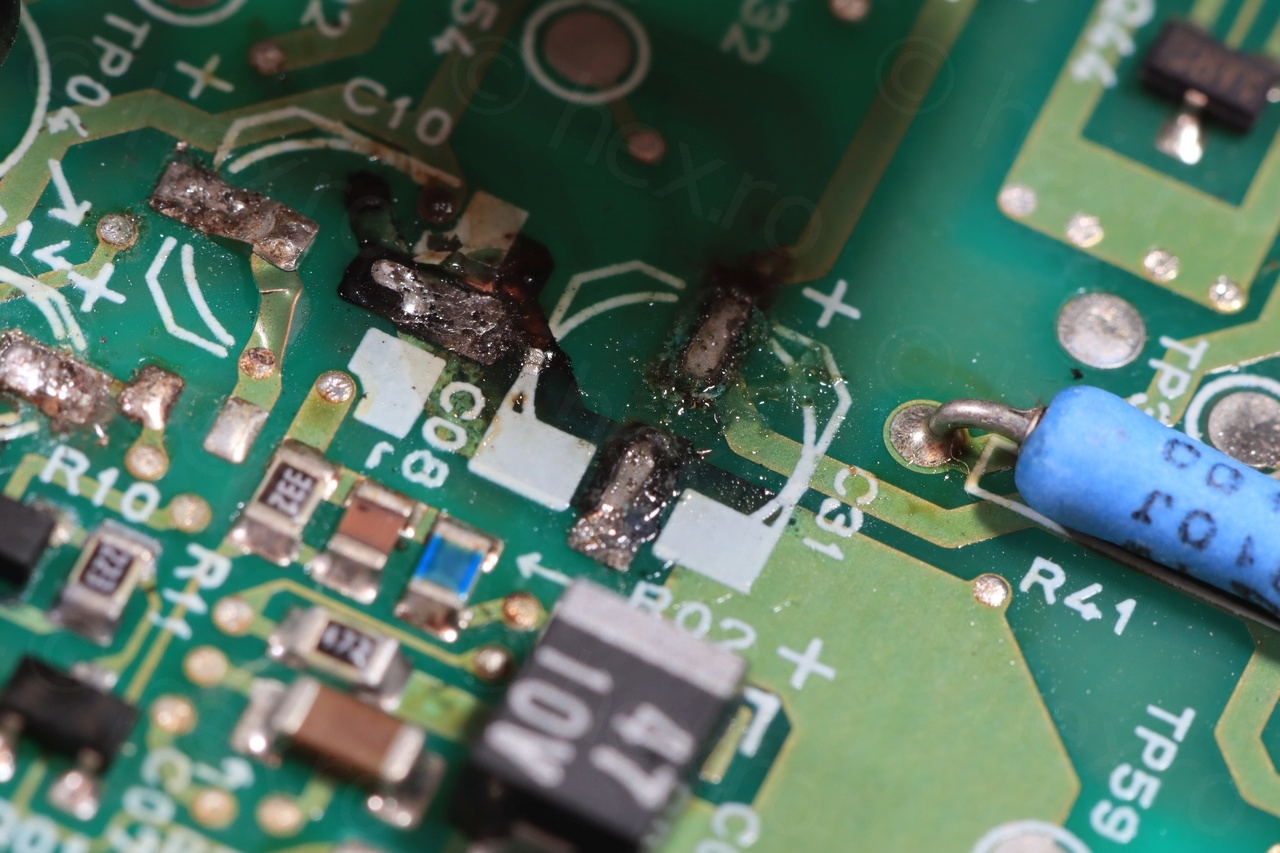
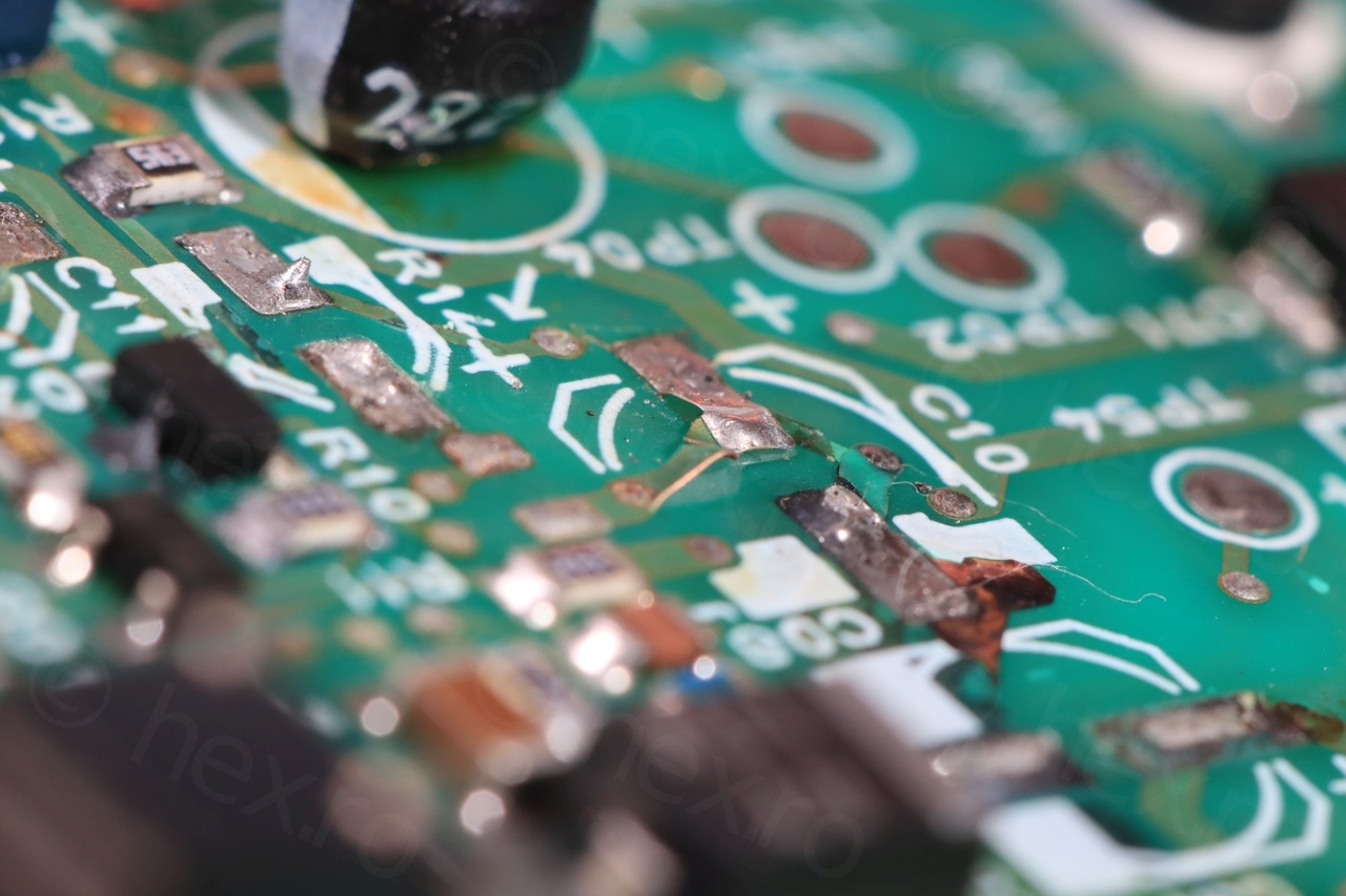
I have cleaned the best I could (Isopropyl alcohol) and waited few days for good capacitors to arrive:

And surprise surprise, the mini CRT turned on 🙂
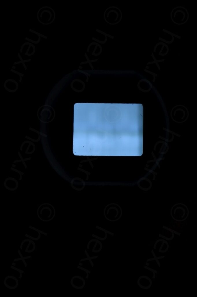
Very blurry at Power ON 
Too bright


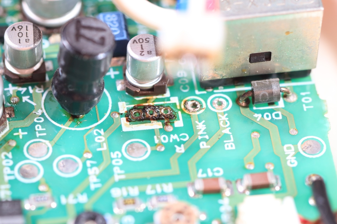
The troubles did not stop though. The CRT was sometimes had oscillating brightness, most of the time ending up being too bright. Sometimes tapping on the driver board would remedy the situation. I have investigated all the connections and decided to first retouch the solder joints of the FBT. This seemed to have improved a bit the situation, but the brightness was still too high, and would also alternating. Hmmm.
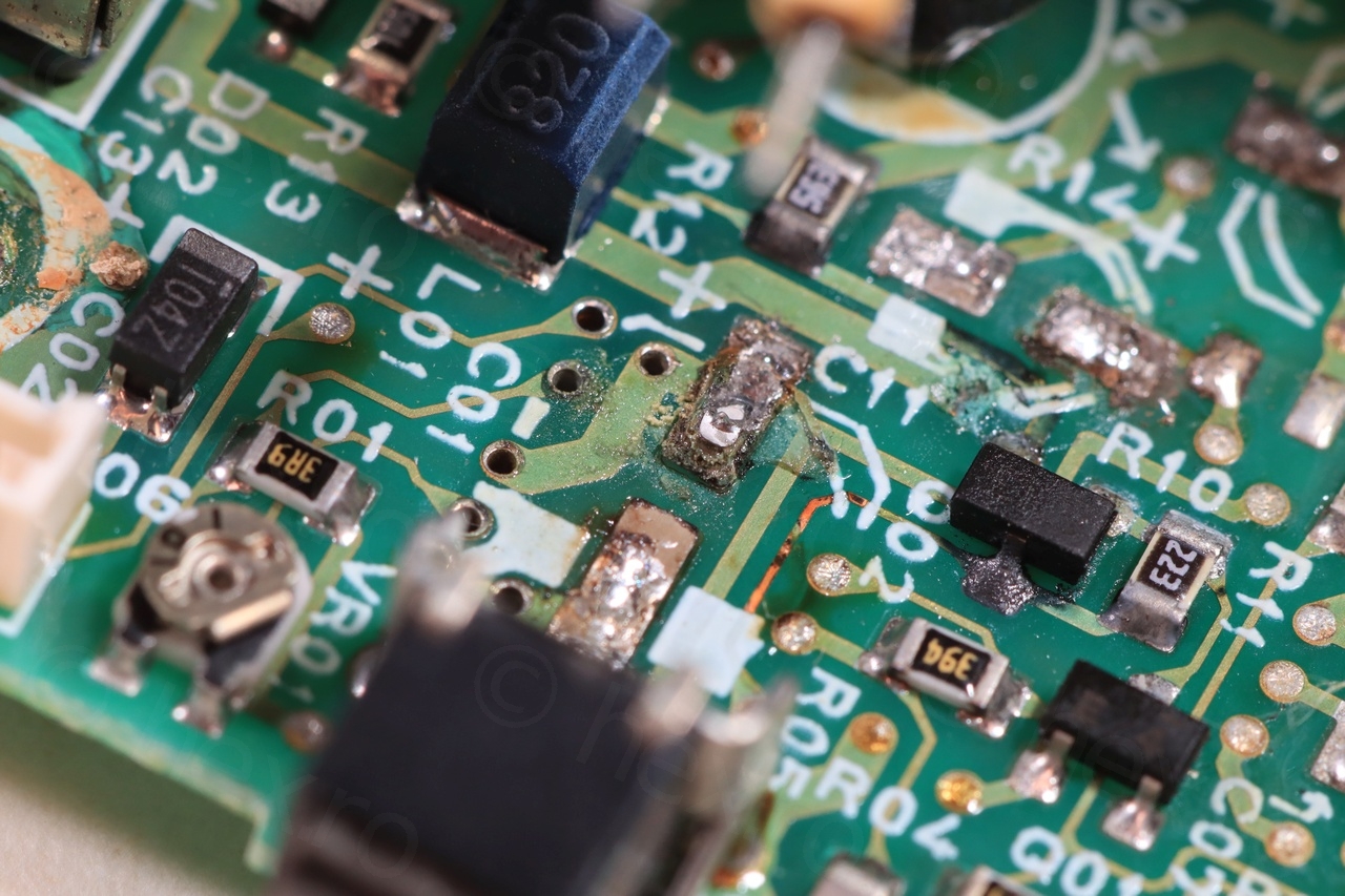
I remembered seeing a brightness potentiometer on the schematics and I located it on the board, VR04:
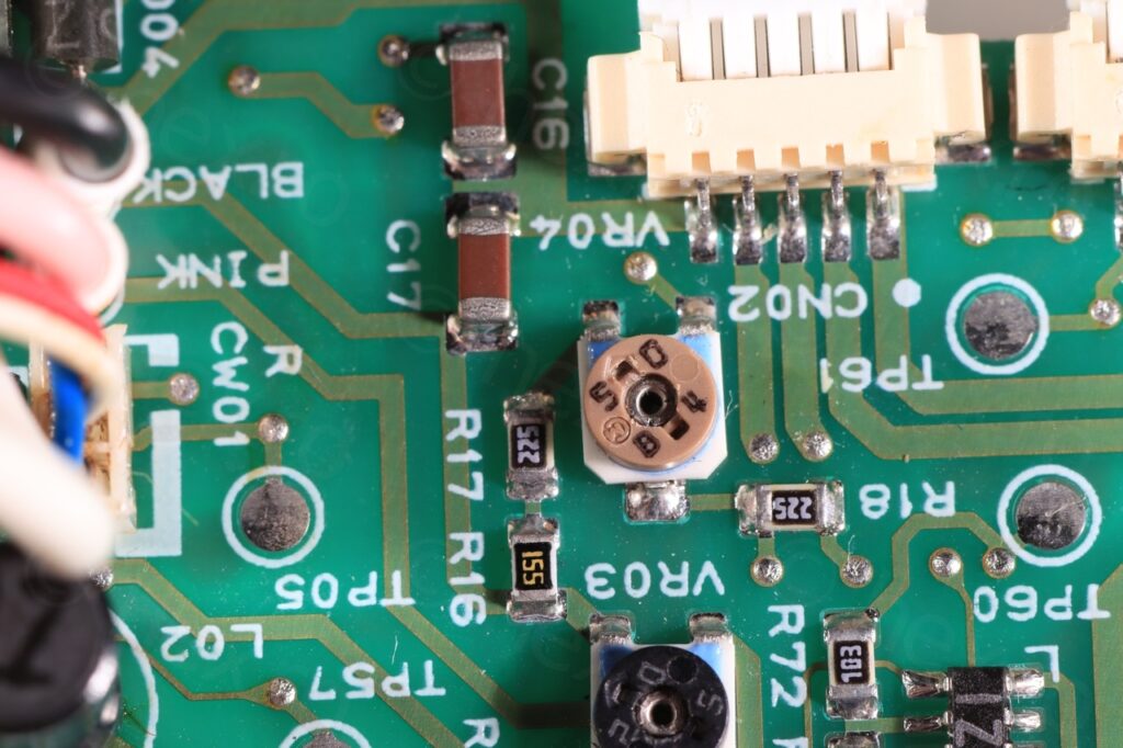
Although it was far from the capacitors that may have leaked, I decided to wash the area with Isopropyl Alcohol and to clean the pot with contact cleaner. This finally stopped the the alternating brightness. The CRT is very sharp but image is deformed a bit:

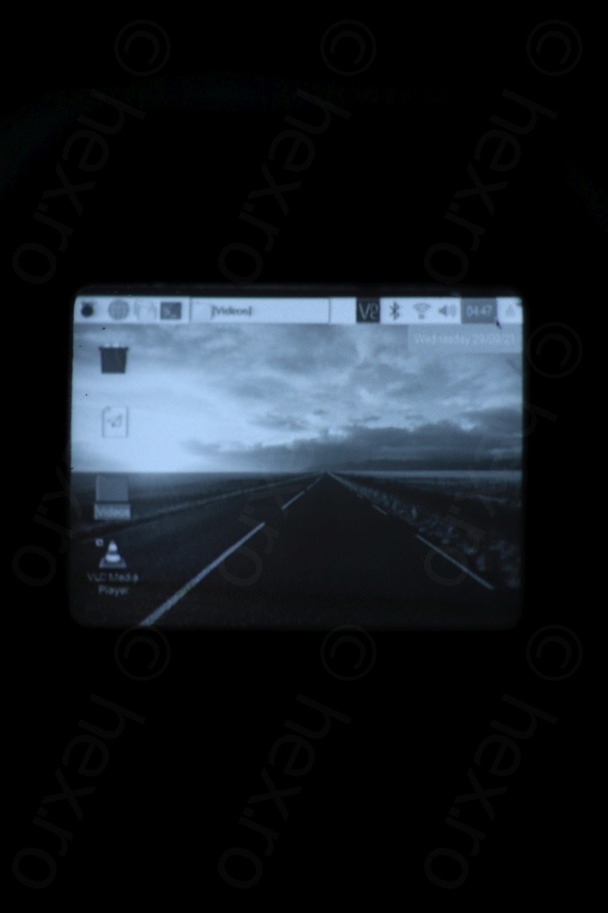
There is still a problem that I was not able to identify, upon powering on the board, the CRT is very out of focus (blurry). It needs a while and then suddenly jump into focus. It may also be that the focus pot is dirty, or 3 more electrolytic capacitors on the Power side which I did not replace (they measured fine in circuit). As I have already spent way more time than I wanted on this board, I did not proceed with more checks or cleanups. Goal was to make sure that the CRT itself works which it does…
The driver board is immune to voltage changes though. Canon did a good job using a 5V voltage regulator, as other driver boards seem sensitive to voltage changes. Here at 6V it draws about 100mA, but as the voltage is lowered, the current draw increases, for example, at 5.4V the current draw is 120mA, and approaching to 5V increases the current draw to 140mA. What I noticed is that at startup, when the mini CRT is very blurry, the current draw is less, at 6V the current draw is about 80mA, then it jumps to 100mA as it self corrects.
I haven’t mentioned the Video IN pin. As the EVT ON (active low) pin is shorted to ground and using the battery connectors for VCC / GND, some little trial and error revealed the Video IN pin location as below:
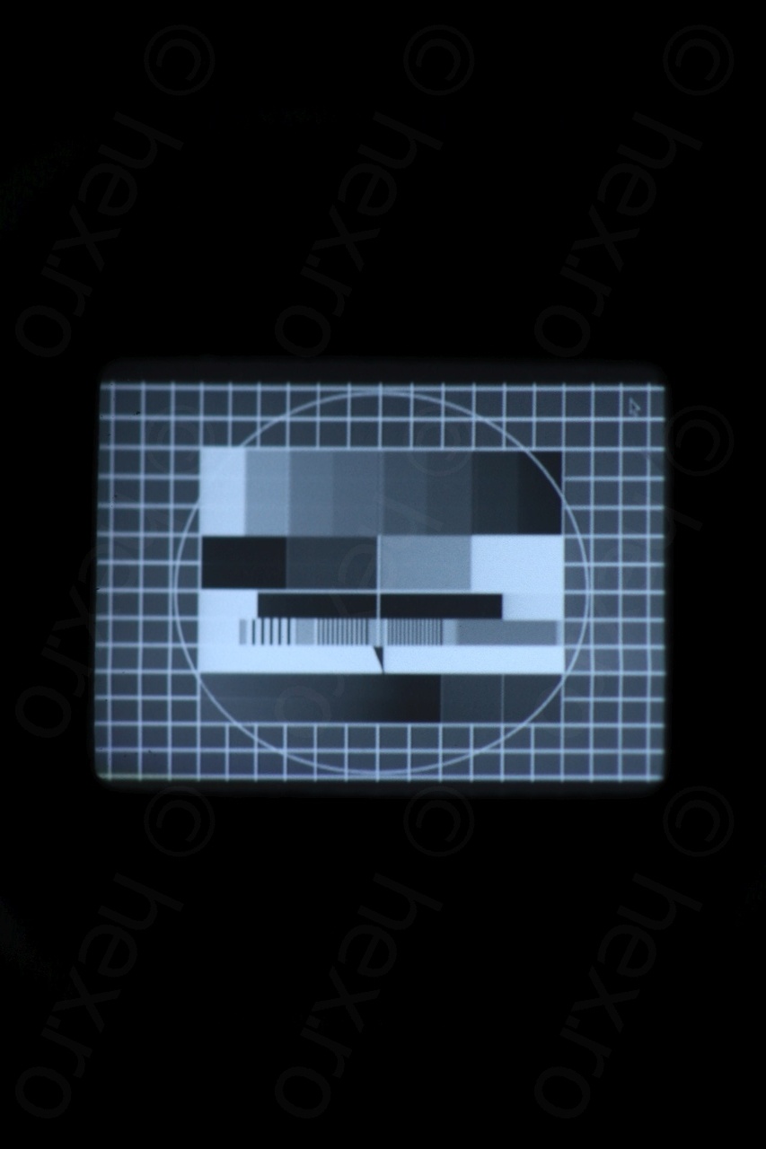
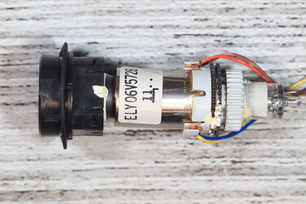
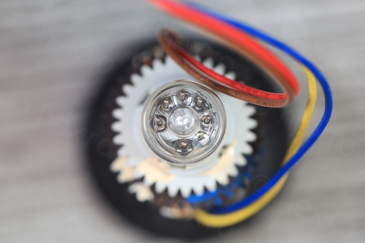
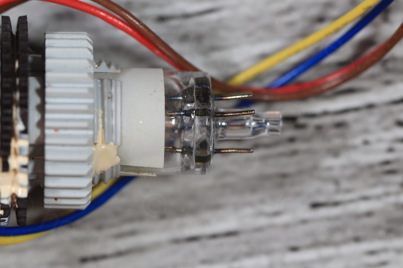
And some more macro shots of the CRT (I had to unplug it to work on the capacitors):
Conclusion is that I’d probably stay away in the future from very old cameras that I could find at the flea markets. This CRT I could salvage due to the schematic (EVF ON – active low) which is one more argument for the Right to Repair movement (having access to schematics and spare parts).
Few more shots before the reassembly of the hand grip:
Of course, no review is complete unless I can play Manic Miner:
ivan
great job, but did you repair all the camcorder or only the EVF section?
viulian
Thank you! Just the EVF section ..