


Introduction
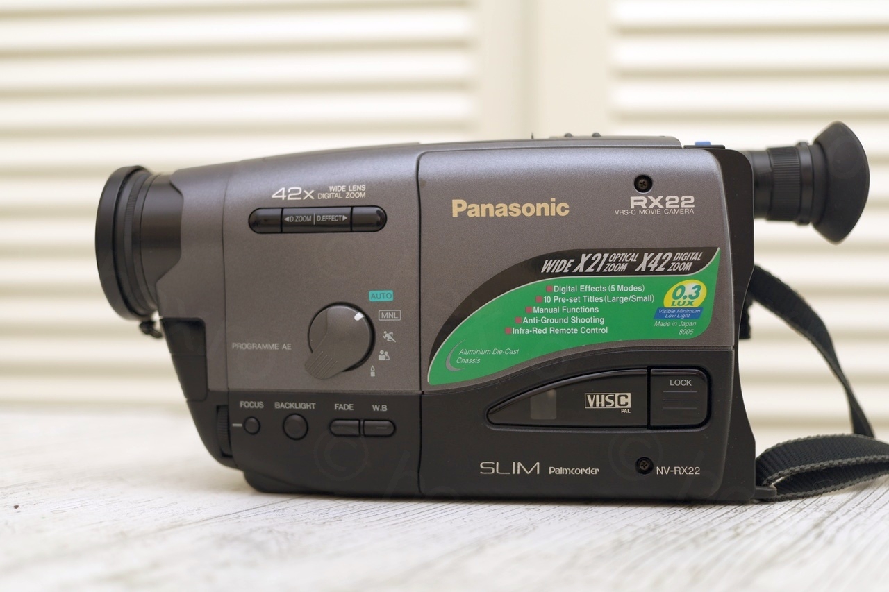
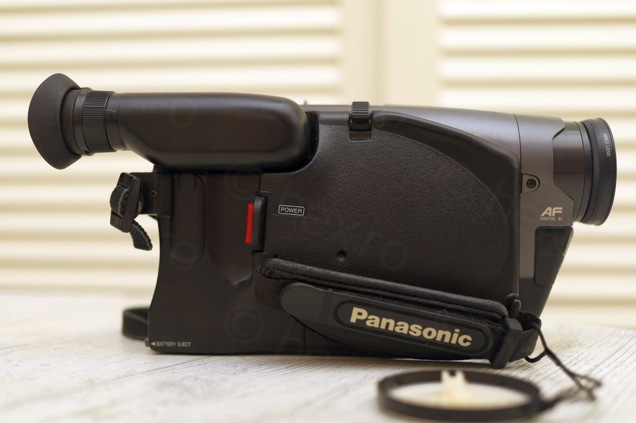
Found this CRT inside a Panasonic NV-RX22EG camera that I bought at a flea market. This seems to be a common CRT, since it is the 4th time I encounter it.
Camera overview
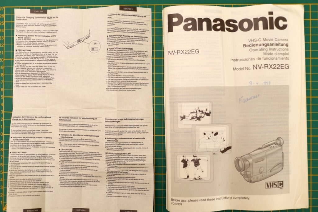
Camera was sold in a Panasonic bag, along with 2 batteries, the charger, Instructions Manual and 2 tapes, 1 tape new.

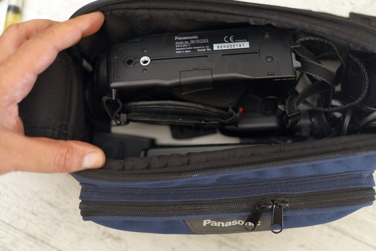
I took out the camera and it looked like new:

The cover of the instruction manual has a hand written date: 9-4-1998 – which I shall assume it was the purchase date 🙂
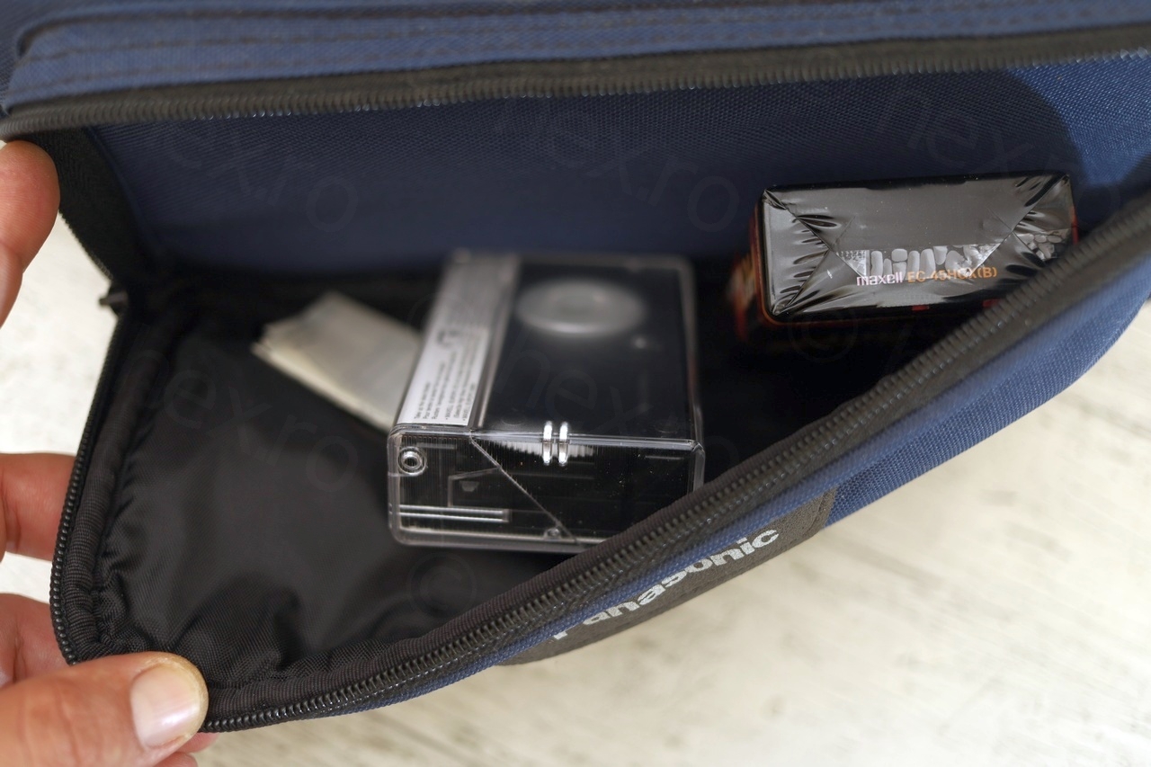
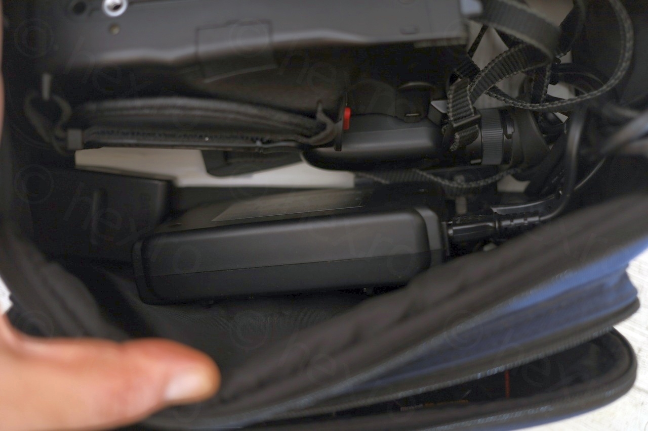
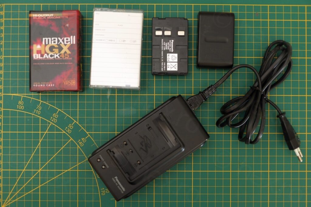
And a photo of the other contents of the bag – the two tapes, two batteries and the charger. I will reuse the charger cable – it is useful, as some of the older devices that I find at flea markets don’t come with the cable itself.
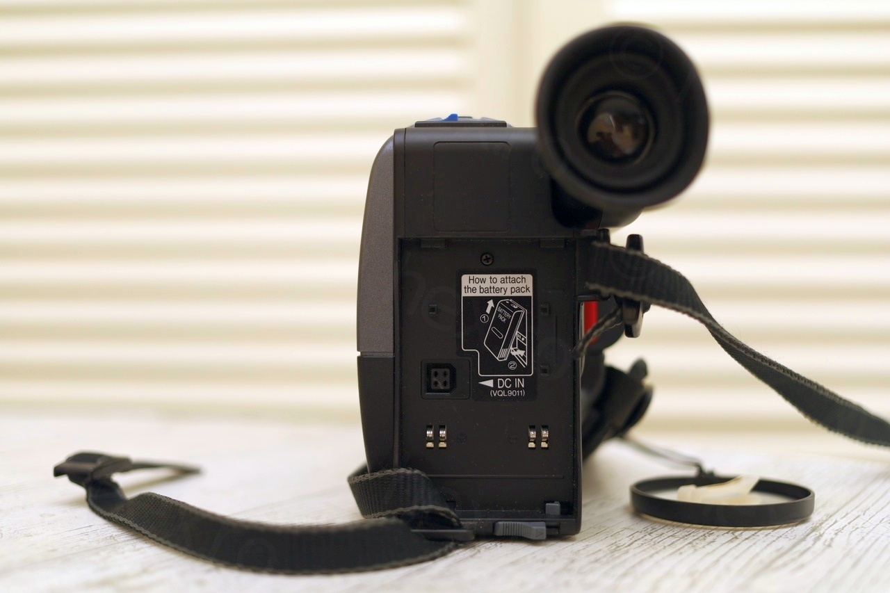
I have tried to power on the camera by injecting power to the battery pins. I think it started reacting around 7V, but I do not remember exactly. It did start up – at least I could check that the CRT is functional. However, there was an F-51 code shown on display and a Google search pointed me to normsweb.com where F-51 means that the focus drive motor is not working. Okey …
Dismantling the camera
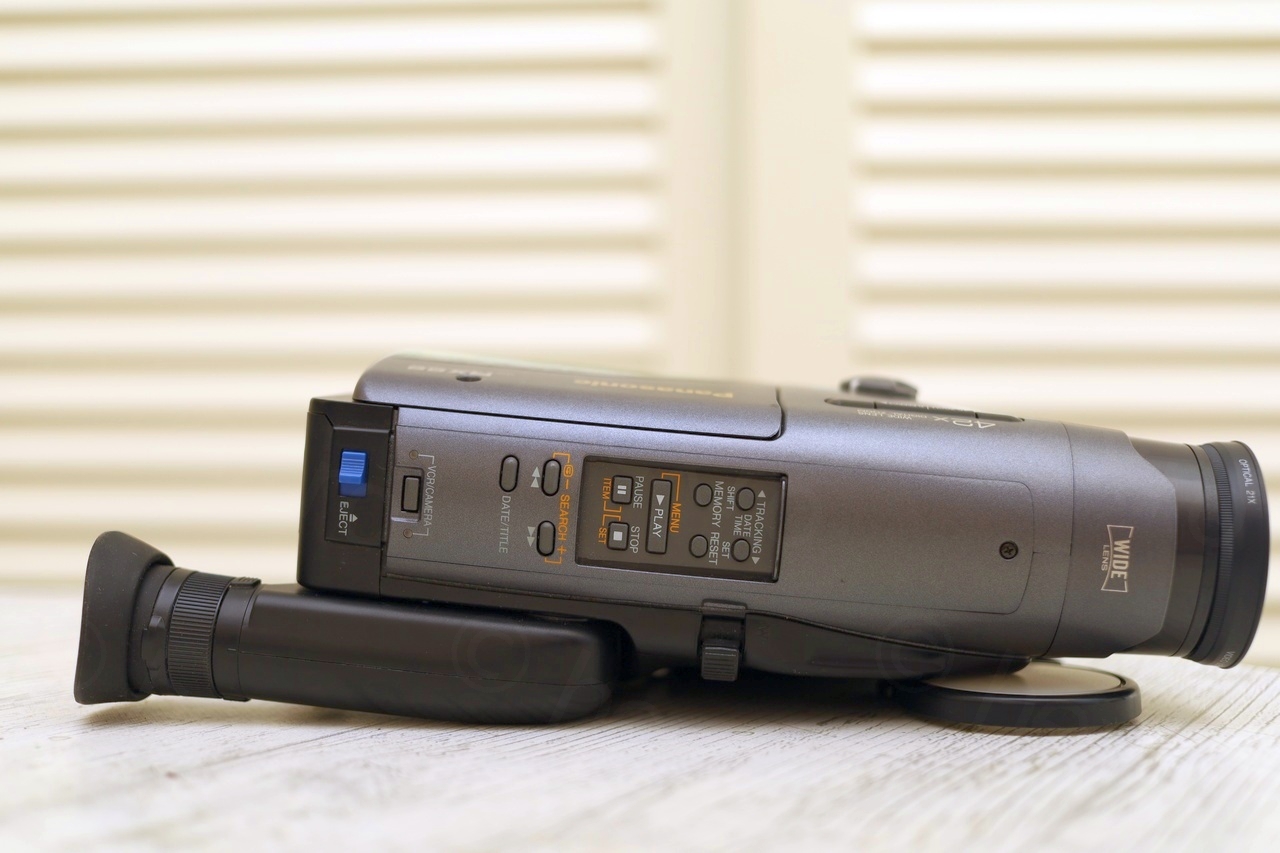
Dismantling the camera is easy. No hidden catches, you just need a small screwdriver to un-clip the side of the view finder – provided that all screws are out:
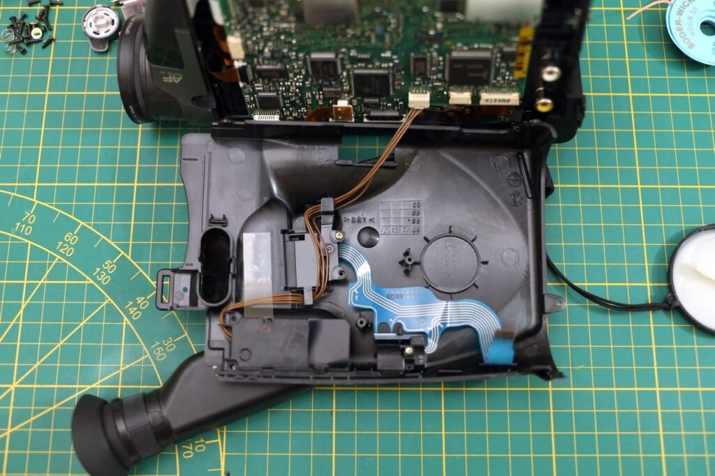
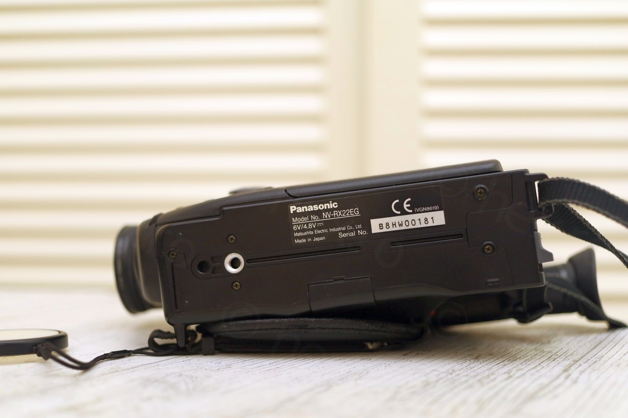
Visible on this photo (stamped on the back of the cover) is the camera’s manufacturing date: Q1 of 1998. It matches the date that was handwritten on the Operating Instructions Manual.
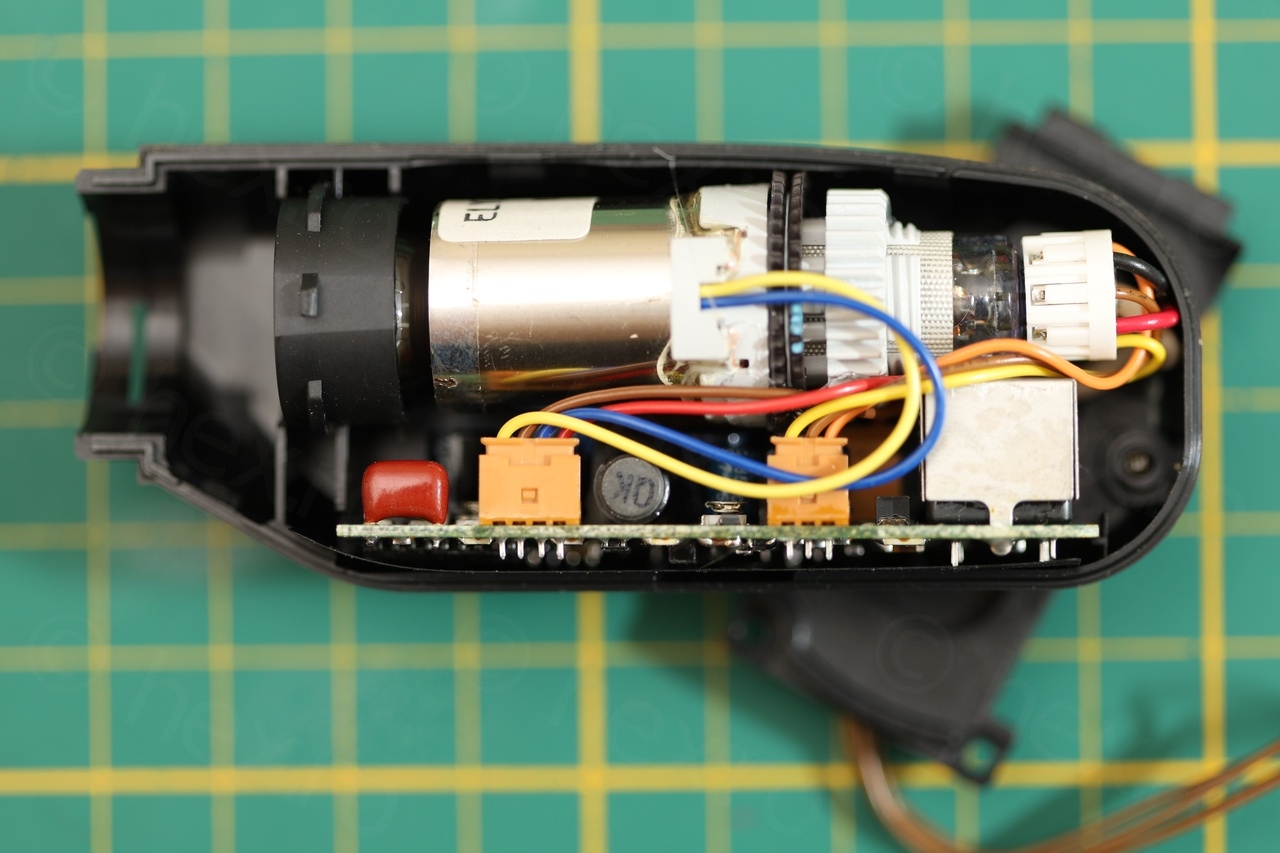
Electronic View Finder Unit
Removing the EVF unit was tricky. I could not figure out how it was attached, nor what clips I would have to unclip to free it from the camera body. With some pliers I had to cut away the inside plastic paying attention not to clip the brown wires. Once the supporting plastic was cut away, the EVF was free unharmed:
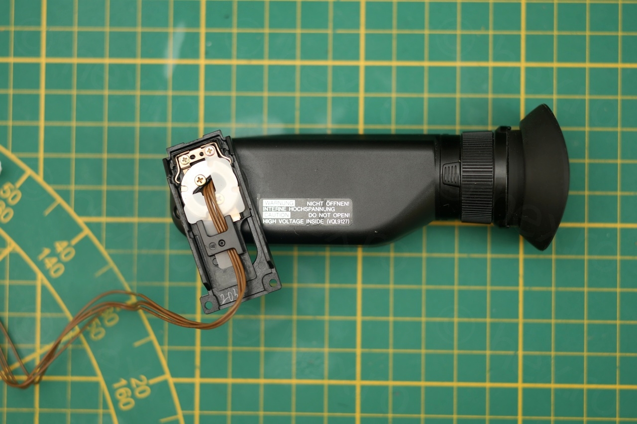
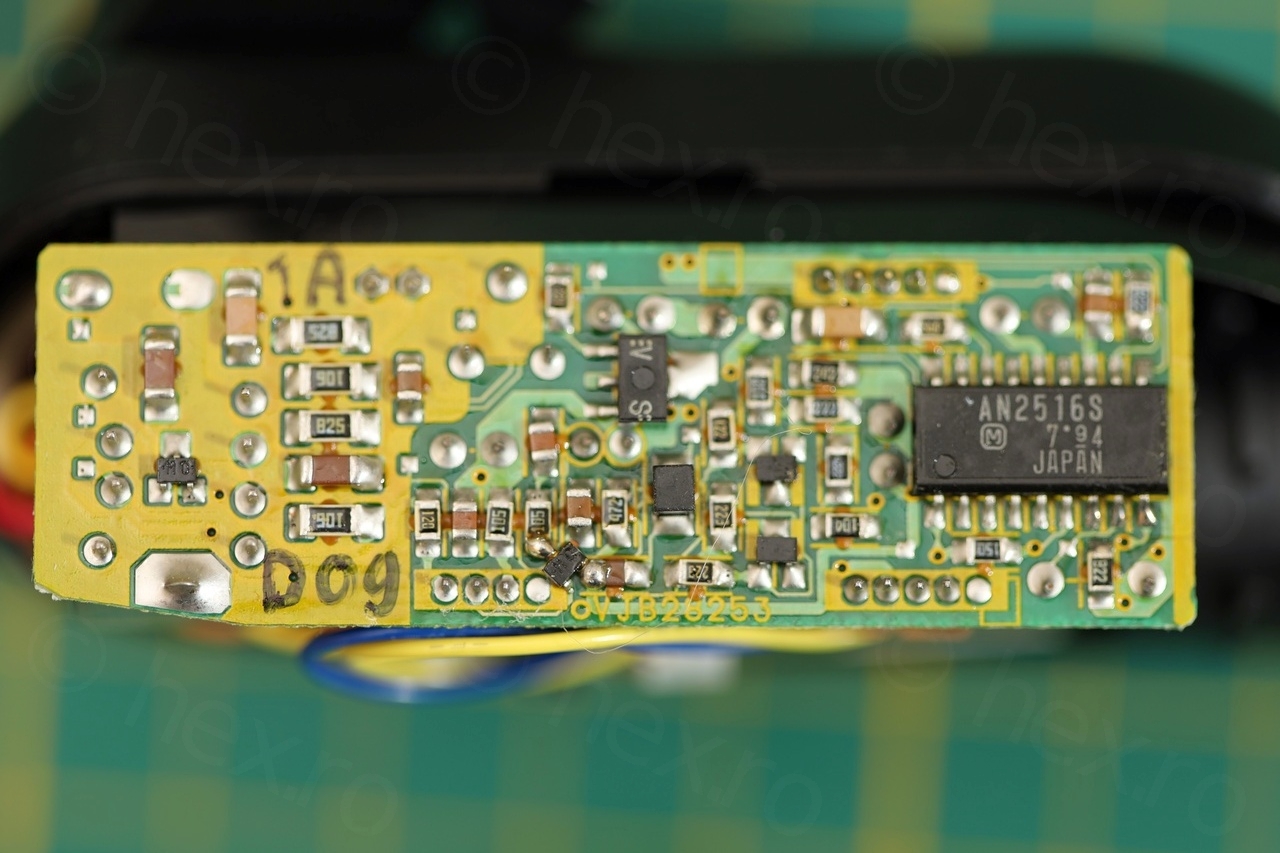
There is a single marking on the case of the EVF which I hope is the model: VQL9127. A look inside reveals that it has an AN2516S Driver IC.
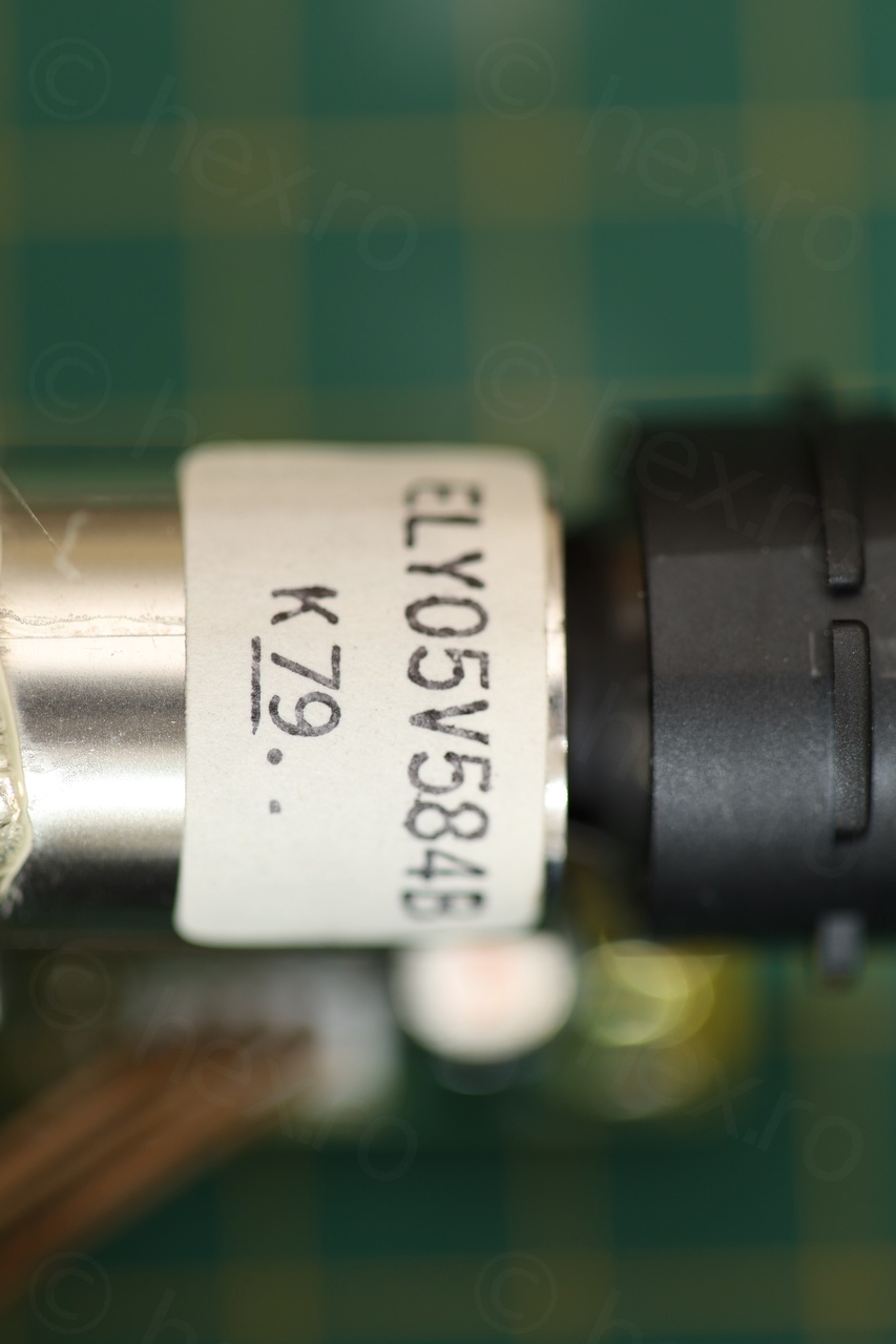
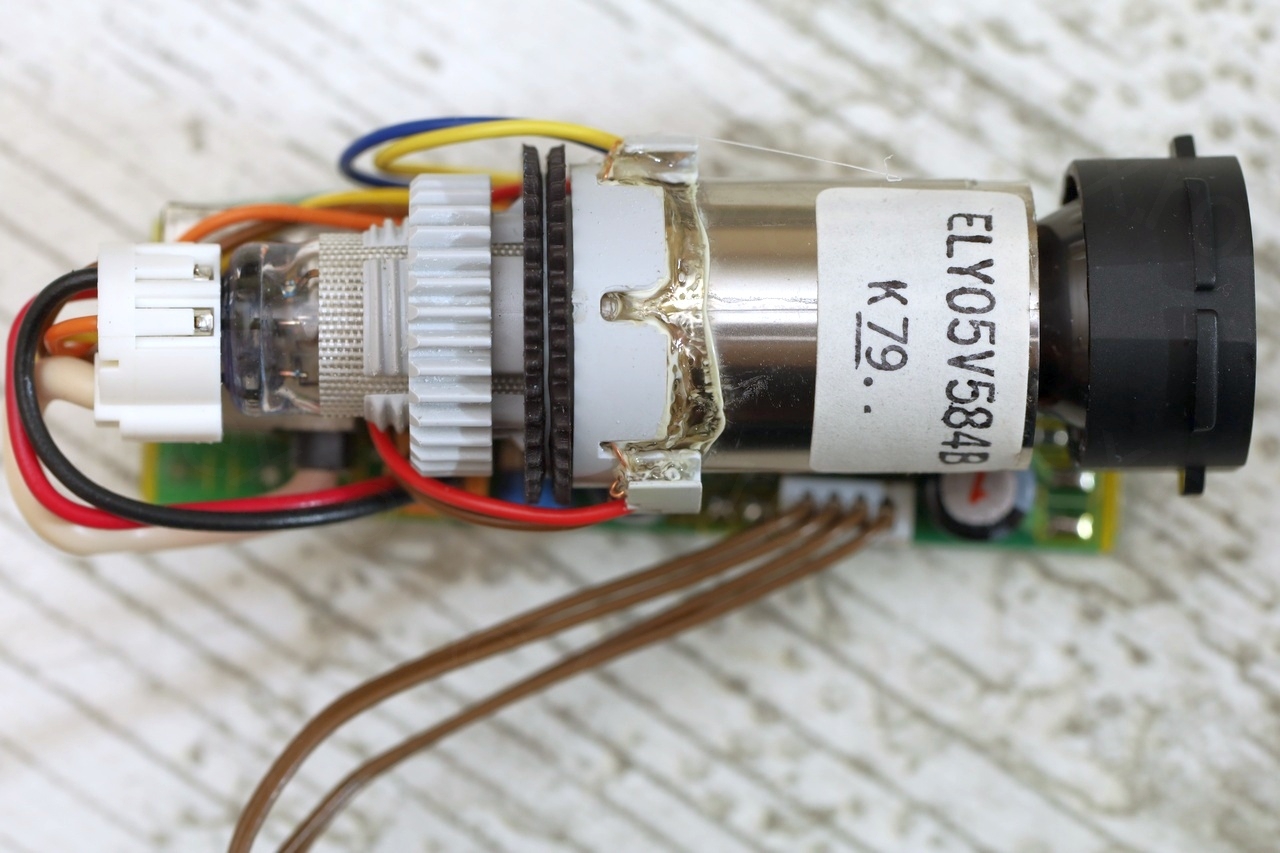
And below few more photos of the CRT itself:

Reverse Engineering the Signal wires
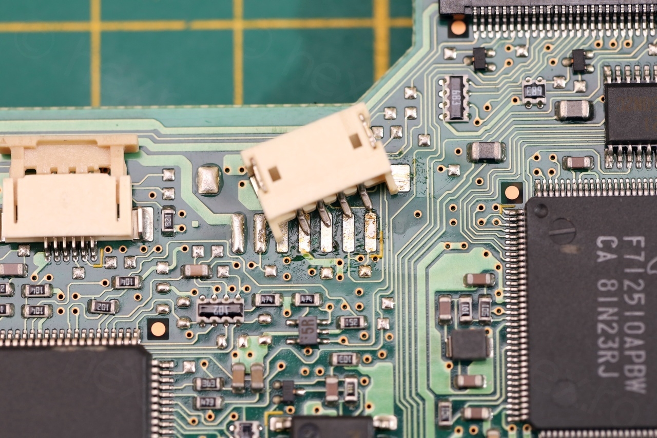
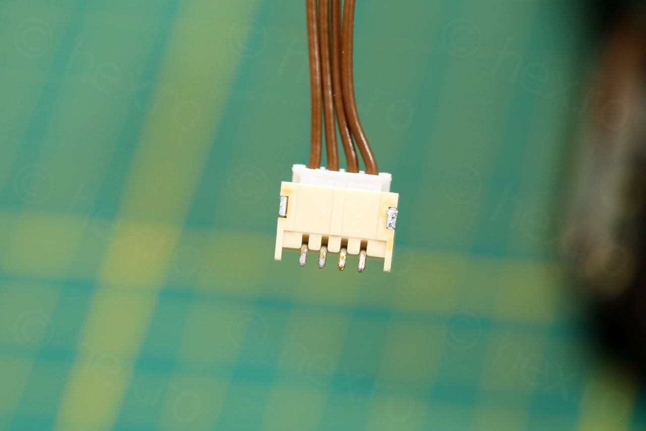
This EVF seemed easy – 4 wires in total to reverse engineer. First though, the connector has to be recuperated – as this makes it easier to attach signal clamps.
To find out which wire is which, I applied the technique where the exterior of the Fly-Back Transformer is connected to GND. Then, there are some FBT pins that are not GND but if they have continuity to the plug itself, then they are VCC.
Once VCC and GND were identified with the continuity meter, it was just a matter of trial and error (on the other remaining pins) to locate which one is Video IN – or so I thought!
The correct connection diagram is this one:
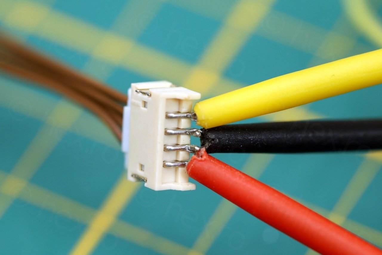
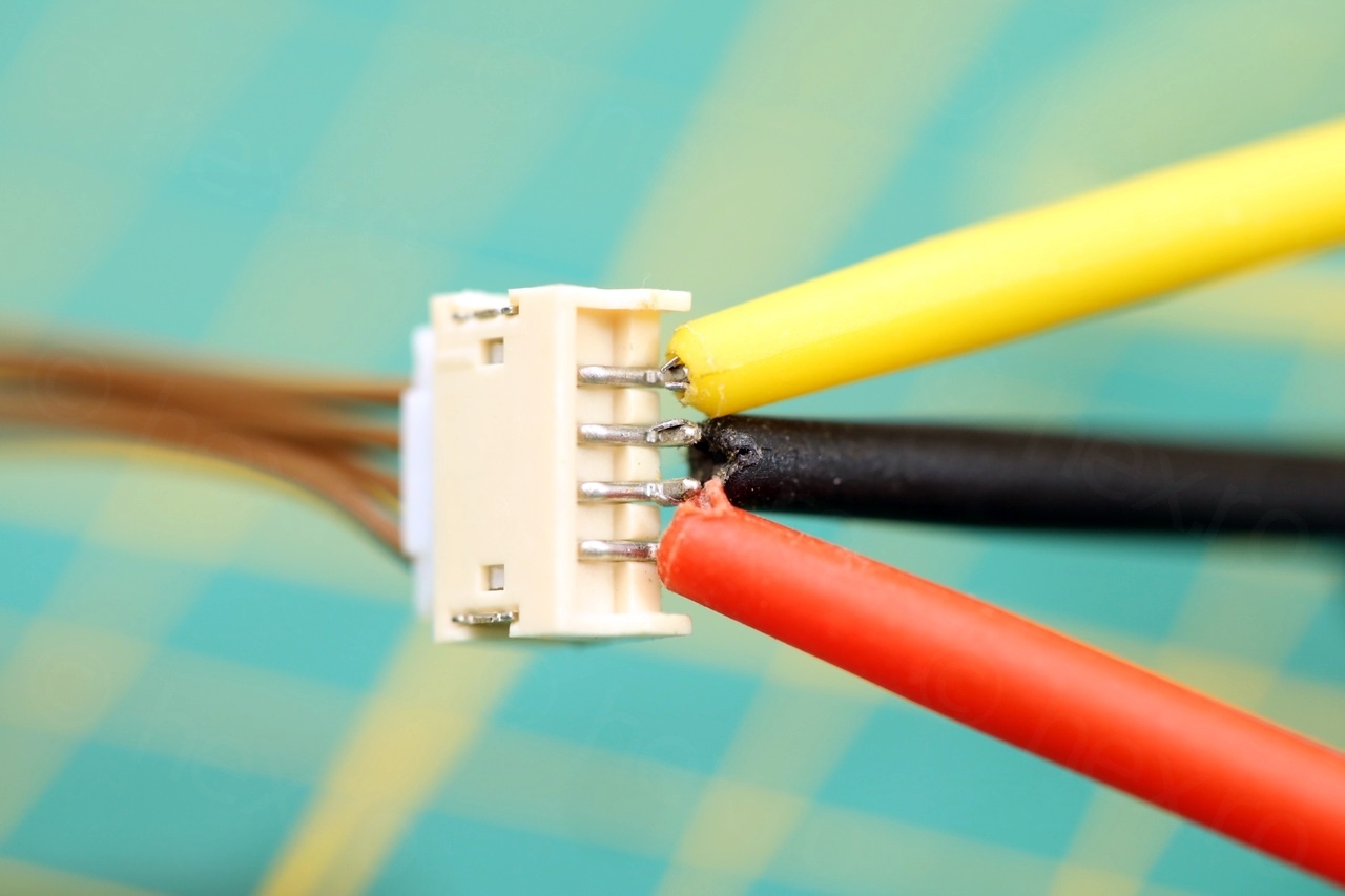
The first pin from the bottom is VCC, the 2nd and 3rd must be connected to GND (although only 2nd is real GND) and 4th is Video IN.
After identifying VCC and GND (1st and 2nd pin respectively), trial and error with Video IN revealed 3rd pin as reacting and trying to produce an image. However, the image was garbled:
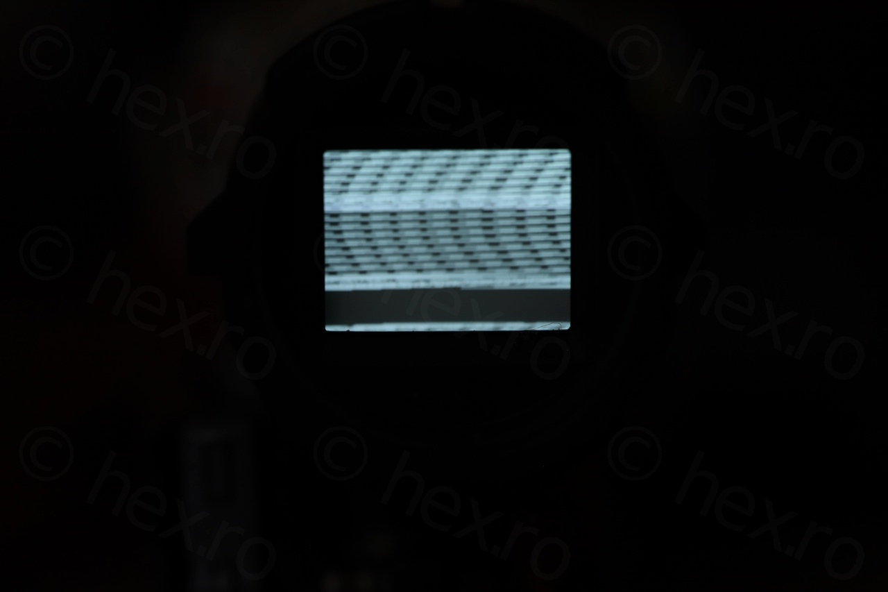


This was puzzling … Injecting Video IN on the 4th pin was not producing any image – which one is which ?!
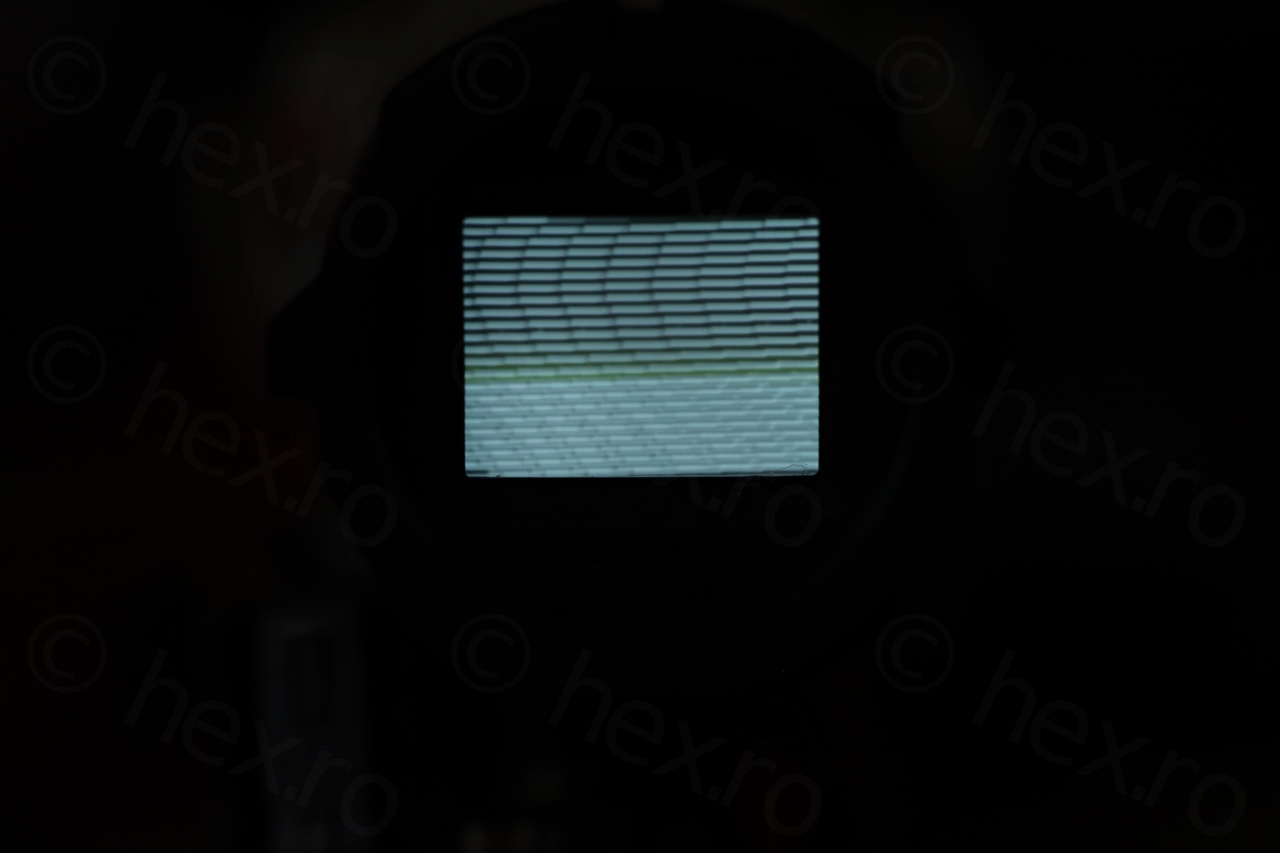
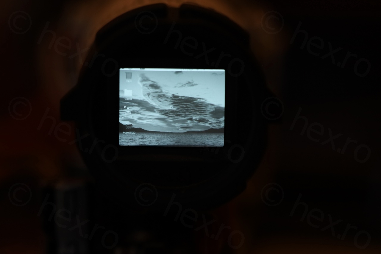
I had a sneaky suspicion that one of the other pins must be either GND or VCC (a way for the camera to control the Brightness or the Contrast maybe ?) Few attempts later and it turns out if Video IN is provided on the 3rd and if 4th is hooked to GND, then an inverted image appears. Aham! So they must be swapped! Finally, correct image appeared:


I thought this was a boring dismantling, but it turned out there was a small challenge 🙂
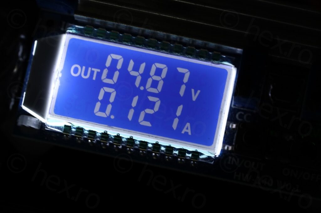
BTW, the sharpest image appears if the input voltage is 4.87V (according to the cheap power supply I use) and draws 121mA.
Leave a Reply