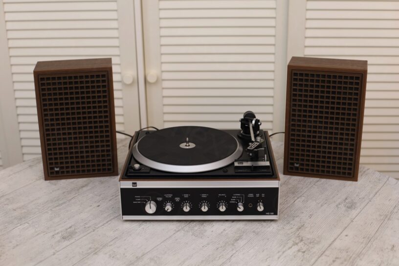


I spotted them just as the flea market sellers were packing for the end of day.
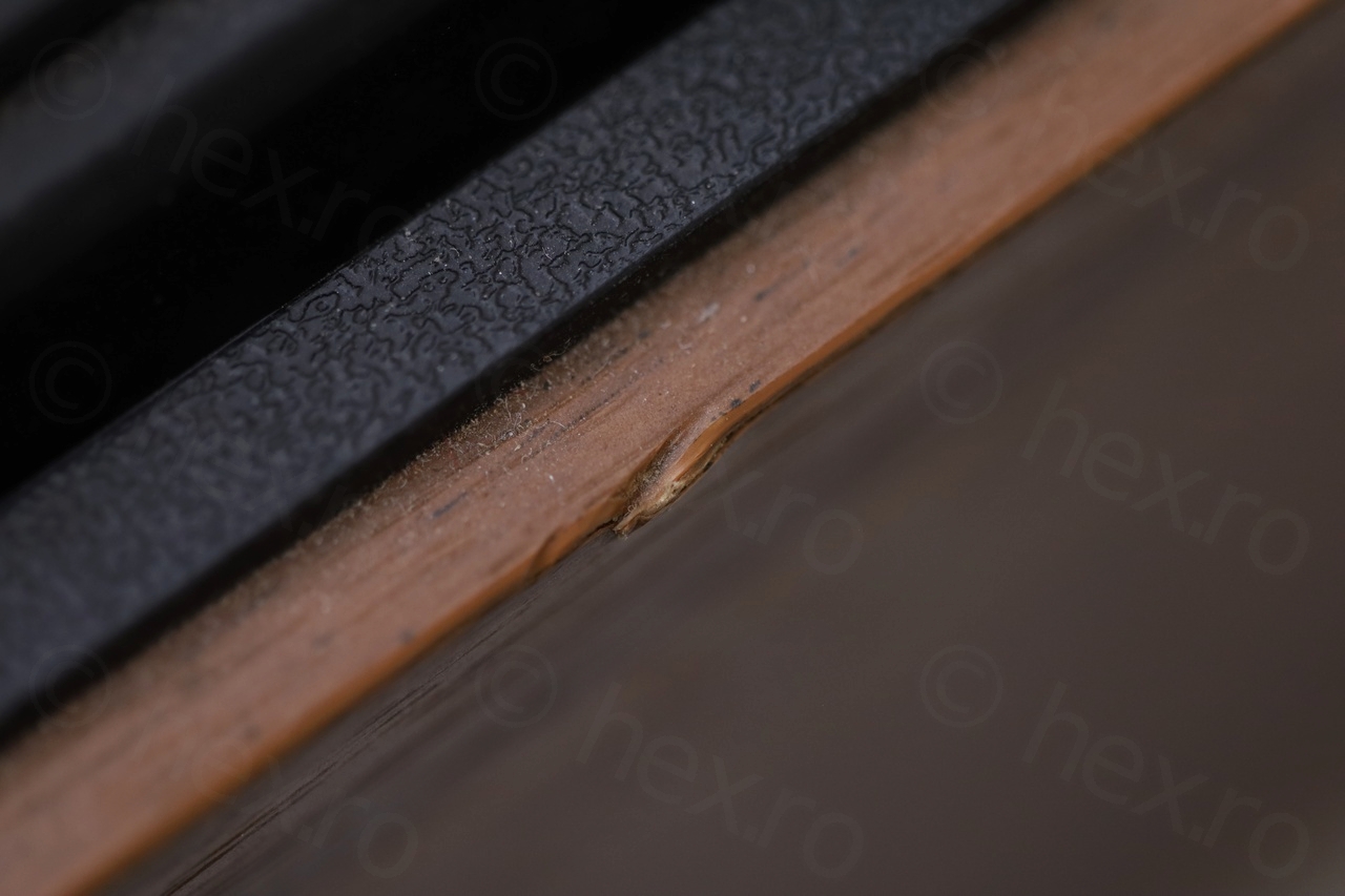
The price was unbeatable – 12€ for asking price and since seller agreed to 10€. I decided to rescue it. Compared to others Duals that are surfacing from time to time, this one seemed early in the daily unloading from / loading back into trucks cycle – not many blemishes nor scratches. Except one of the speakers that had a split case in one of the corners due to mishandling.
A rescue operation may I say, otherwise, few more days into the cycle – maybe the tonearm would have been snapped ?
Table of Contents
- Investigations
- Gluing the split speaker case
- DIY Speaker cables
- Dual knob – cracked plastic
- Opening up the turntable
- Replacing the RIFA capacitors
- Rebuilding the Dual KS 4 module
- Steuerpimpel!
- Dual AW-3 Stacking Spindle
- Dual Amplifier Light Guide
- Unbalanced Output
- Miscellaneous
Investigations
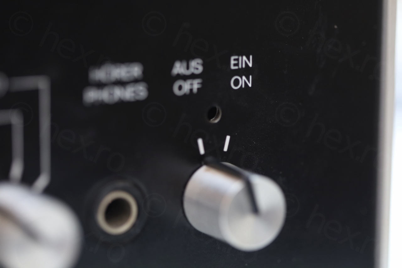
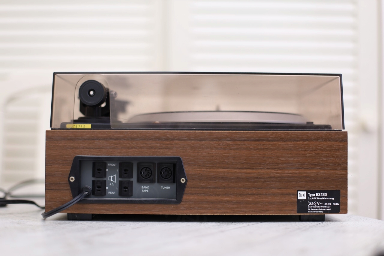
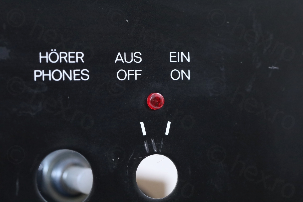
Once home, I had a closer look. Most buttons had their plastic decoration intact, except the On/Off button. The light guide (a small transparent red plastic that was traversing the body of the amplifier, bringing the light from the lightbulb inside, to the outside) was missing. And obviously the split case of the speaker. Also, no speaker cables were provided.
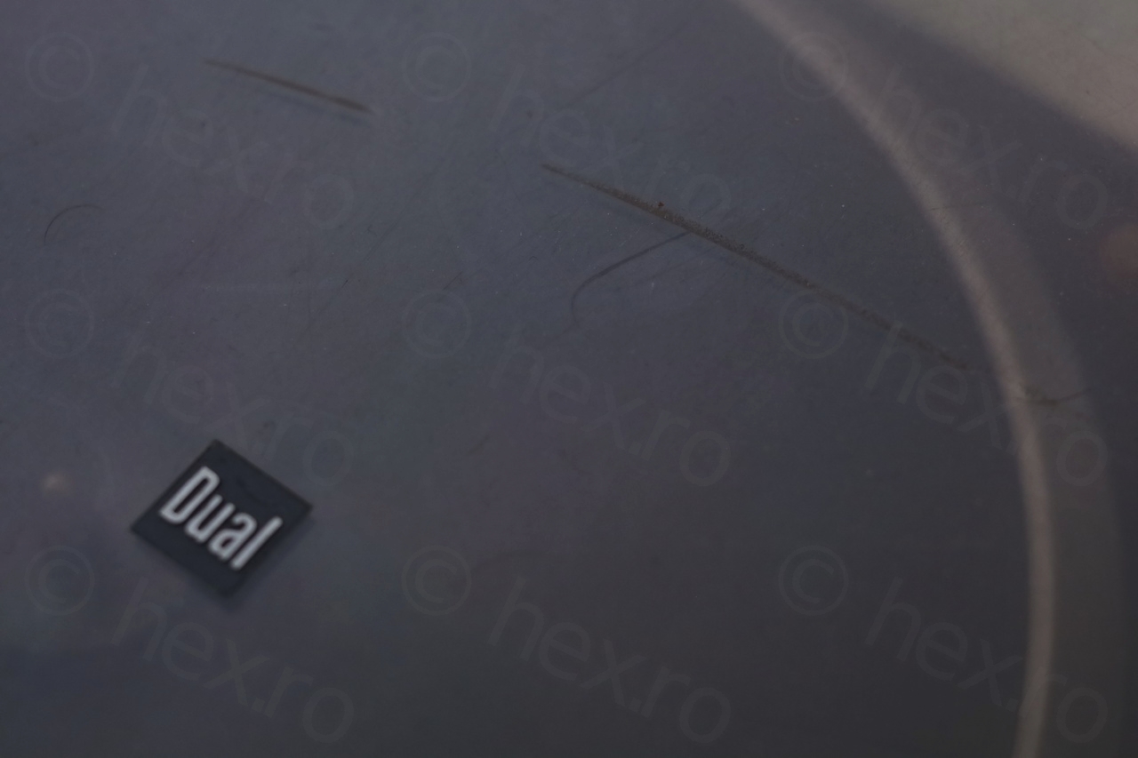
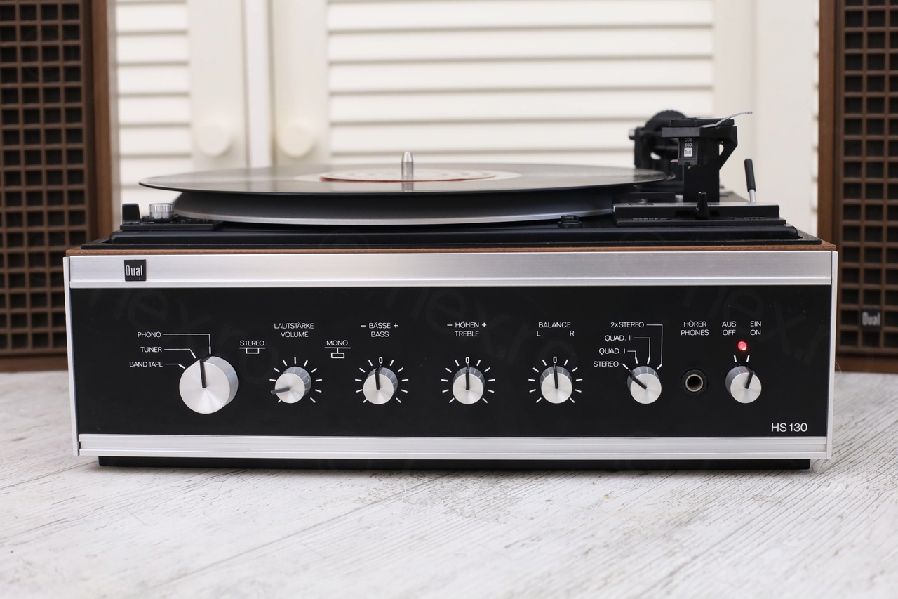
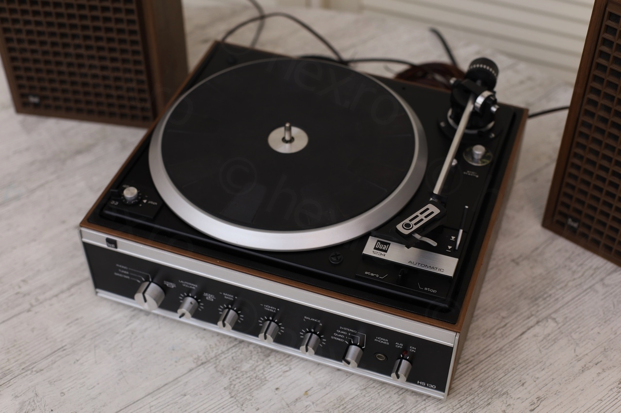
Few more photos with the turntable, as bought. It was dusty, but not too many damages:
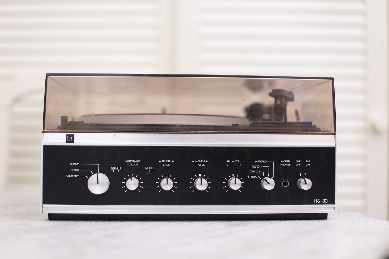
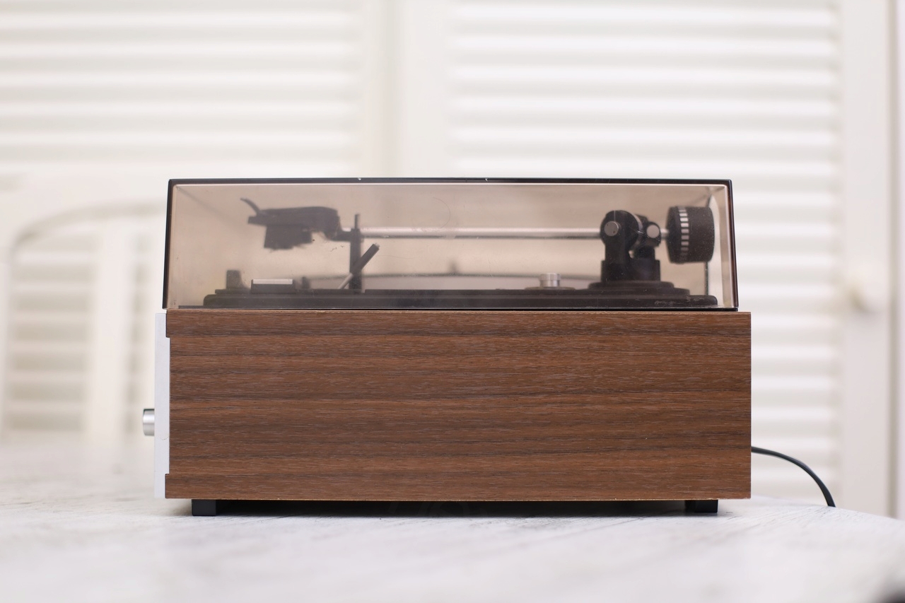

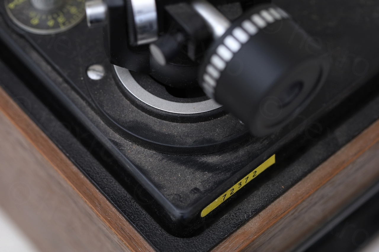


Looks can be deceiving though, this turned out to be an expensive repair. Partially due to me insisting in restoring it (sourcing original parts), part of the poor build quality and brittleness.
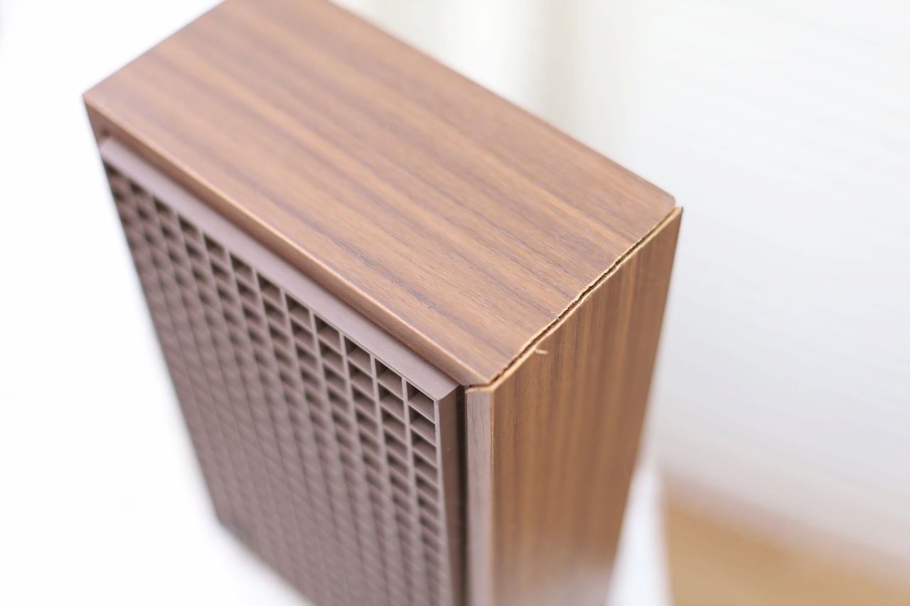
Gluing the split speaker case
Decided to start by trying to glue the speaker case. I don’t have experience working the wood, except using wood glue to keep parts together.
The problem was that that I needed a band clamp to keep the case together. Even by hand it was hard to bring the to sides together. I applied a thin layer of wood glue (using an interdental brush) and clamped everything together for 24h.


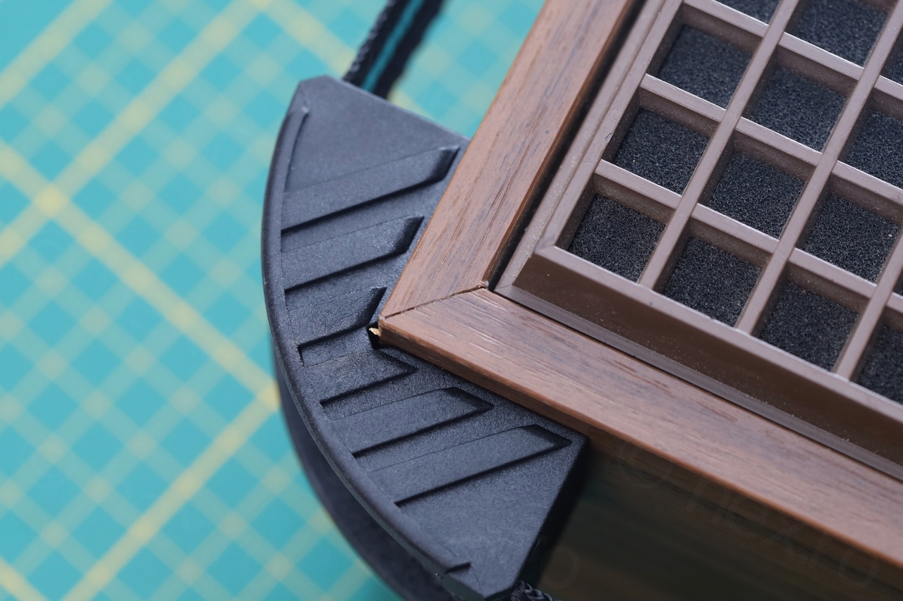
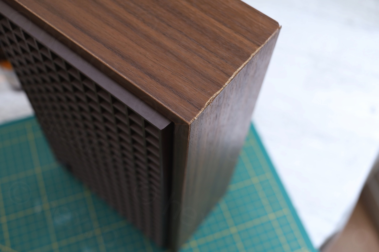
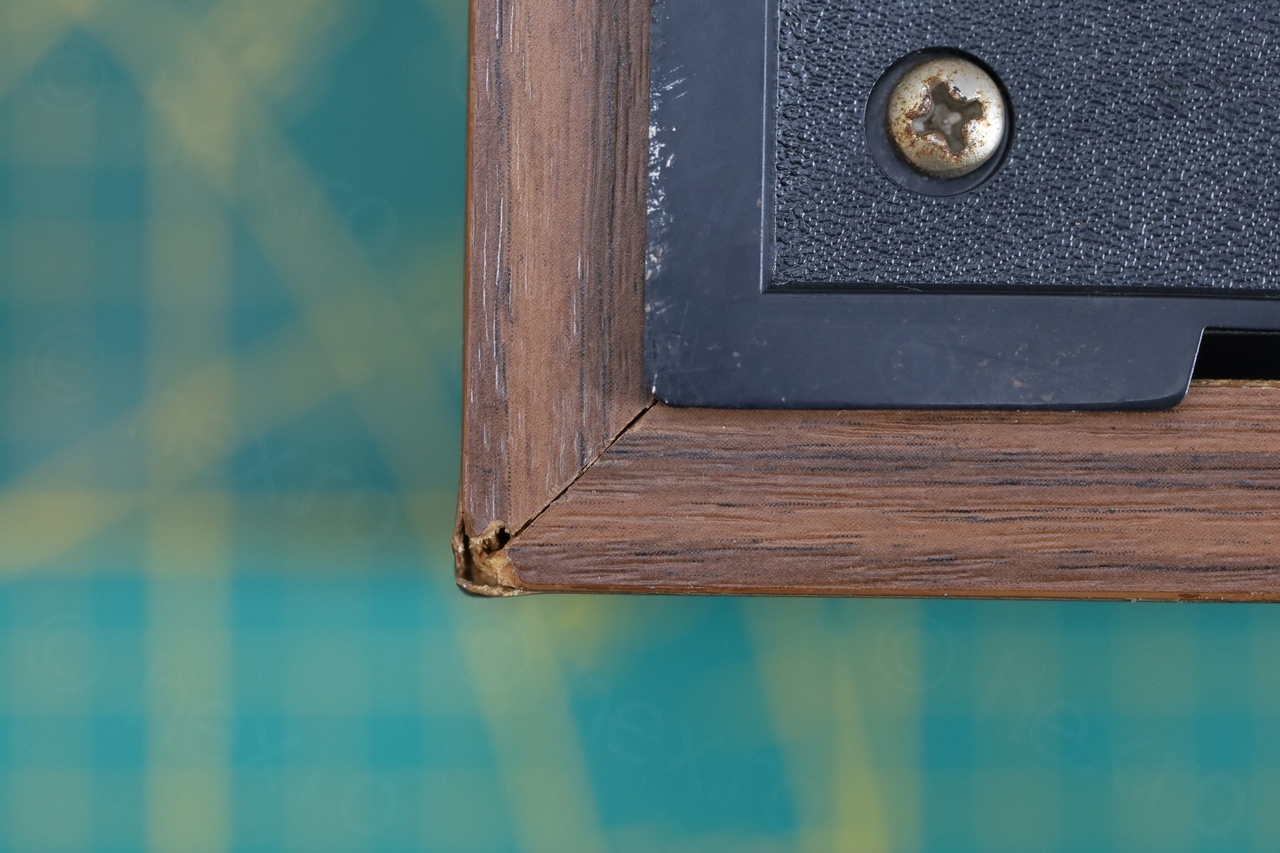

It worked. Almost no visible seam – except the rough joint where the veneer was torn. I assume that the whole case has to be wrapped again – but I think it may be very expensive to do a proper restoration job. I will keep it like this for now.
The band clamp was around 18 euros. Not fair to include tool prices in the repair cost, but I had to buy the tool to proceed. The wood glue I already had from other projects.
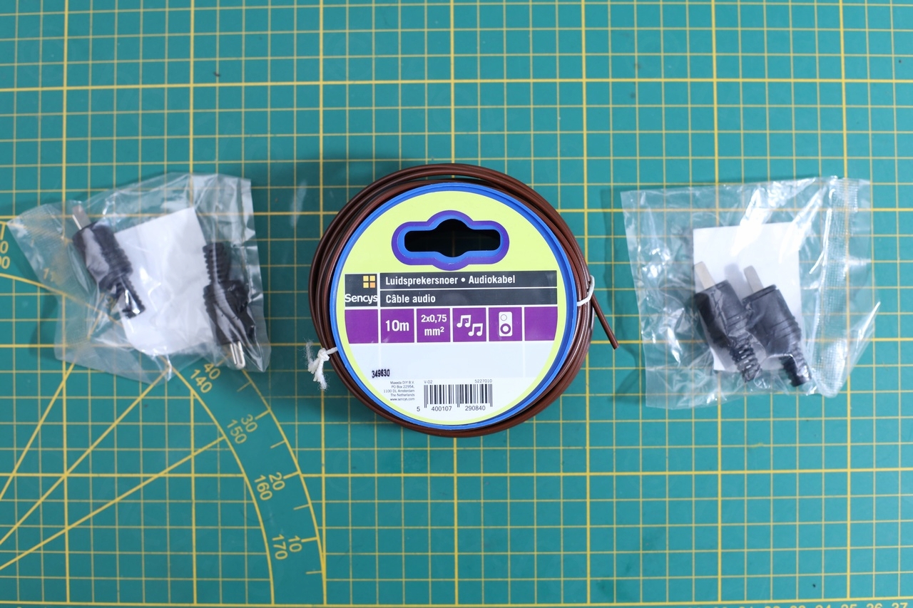
DIY Speaker cables
I don’t think I should bore people with how to assemble speaker cables, but this was also a cost of rescuing the turntable.
The DIN2 plugs were hard to find. Found a seller on amazon.de but I had to pay shipping, so for 10 plugs (I figured let me buy more, I may need more in the future) I payed 22,52€ (shipping included). I also didn’t have the audio cable – so a trip to the local Brico and I bought 10m of audio cable with 10.49€.
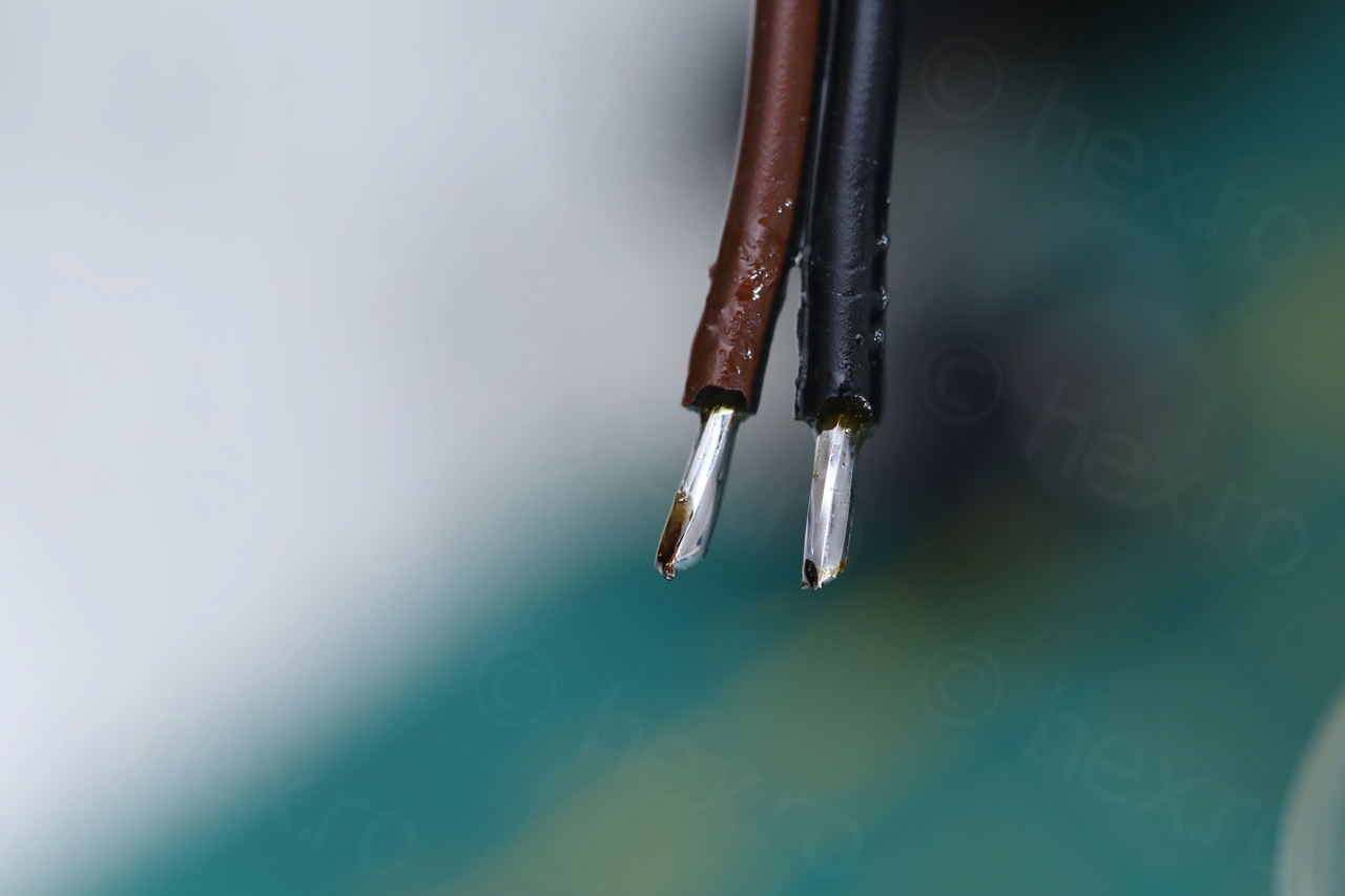

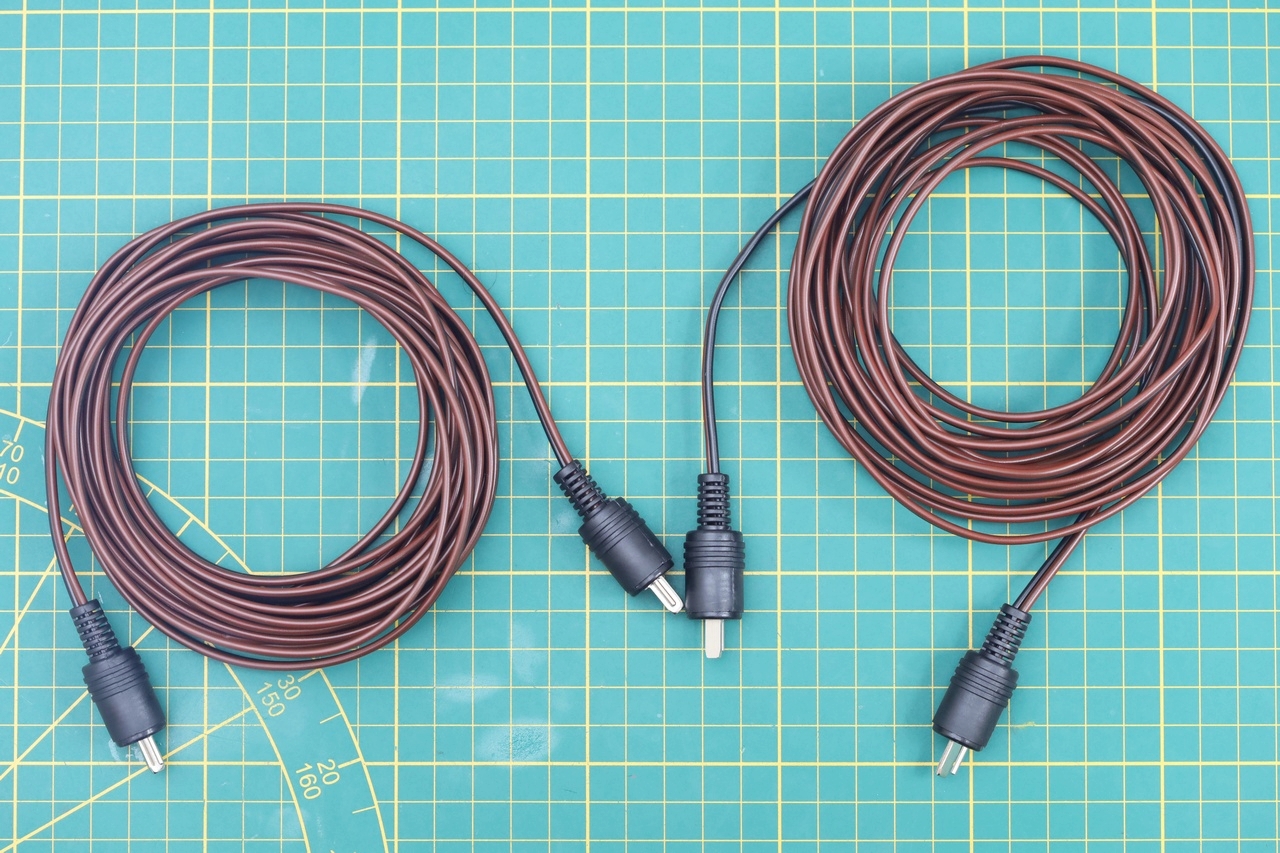
Once the cables complete, I tested the speakers and they were working fine. Used a small audio signal generator for this, not to overload them.
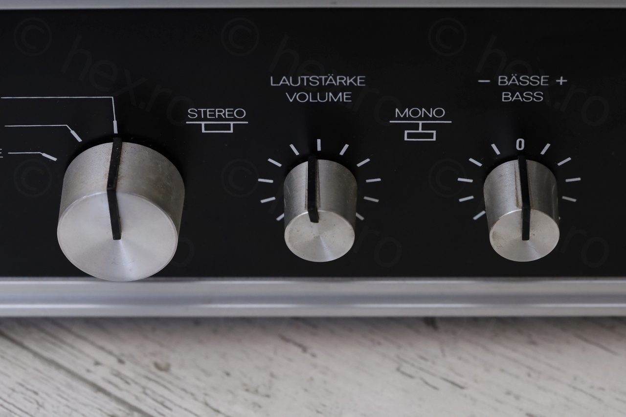
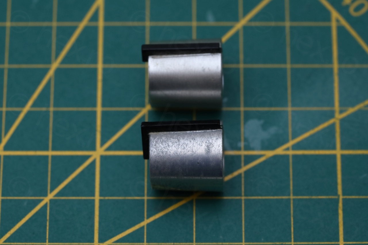
Dual knob – cracked plastic
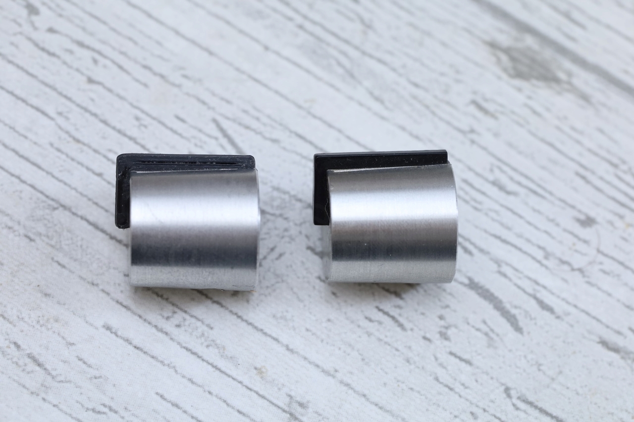
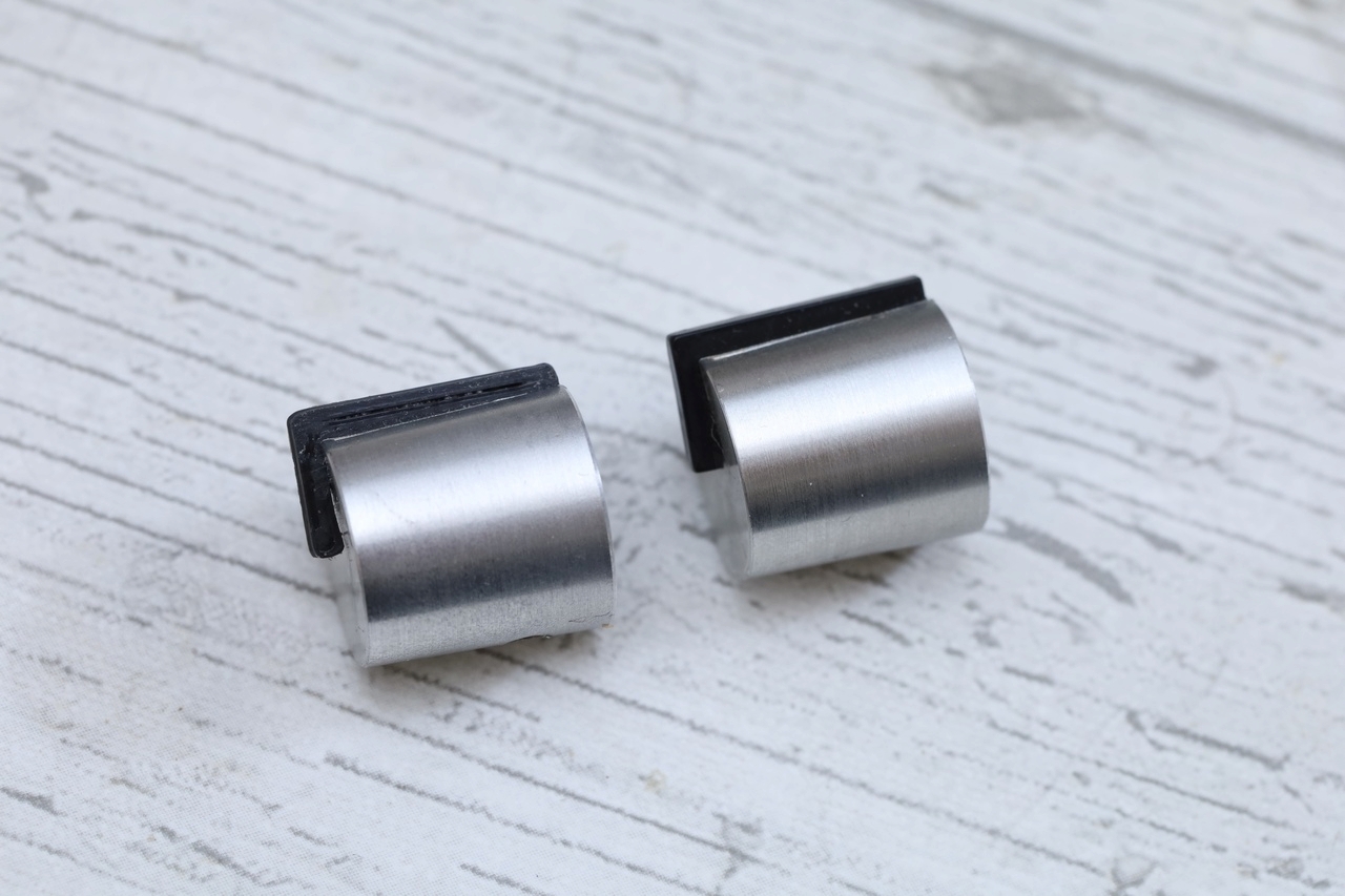
The next on the list was figuring out what to do with the Dual HS130 knob that had its plastic snapped. I knew I could 3D print the missing plastic, but I stumbled on an ebay announcement of a button from a Dual HS130 SL turntable which looked identical to mine. I decided to order it, 11.20€ in total (with shipping).
I got it, but it was a bad choice. First, the button was lot more corroded than the button of my turntable. It also seemed the innards were a little different too.
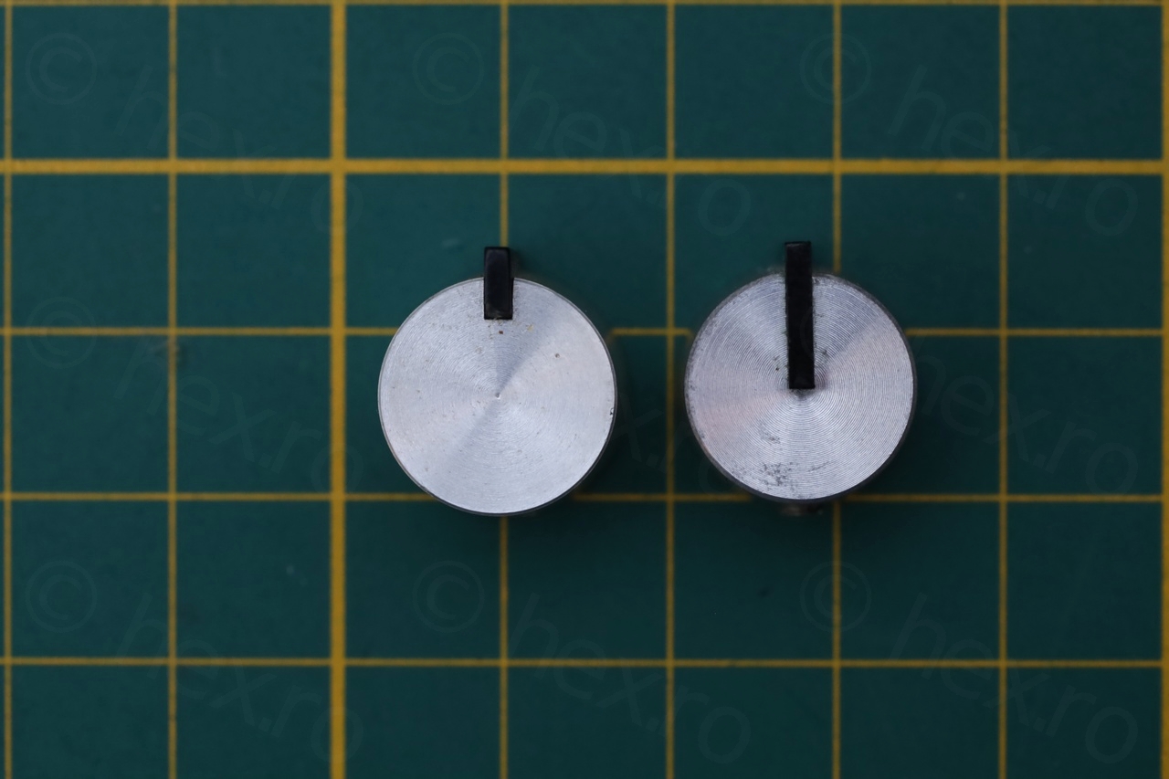
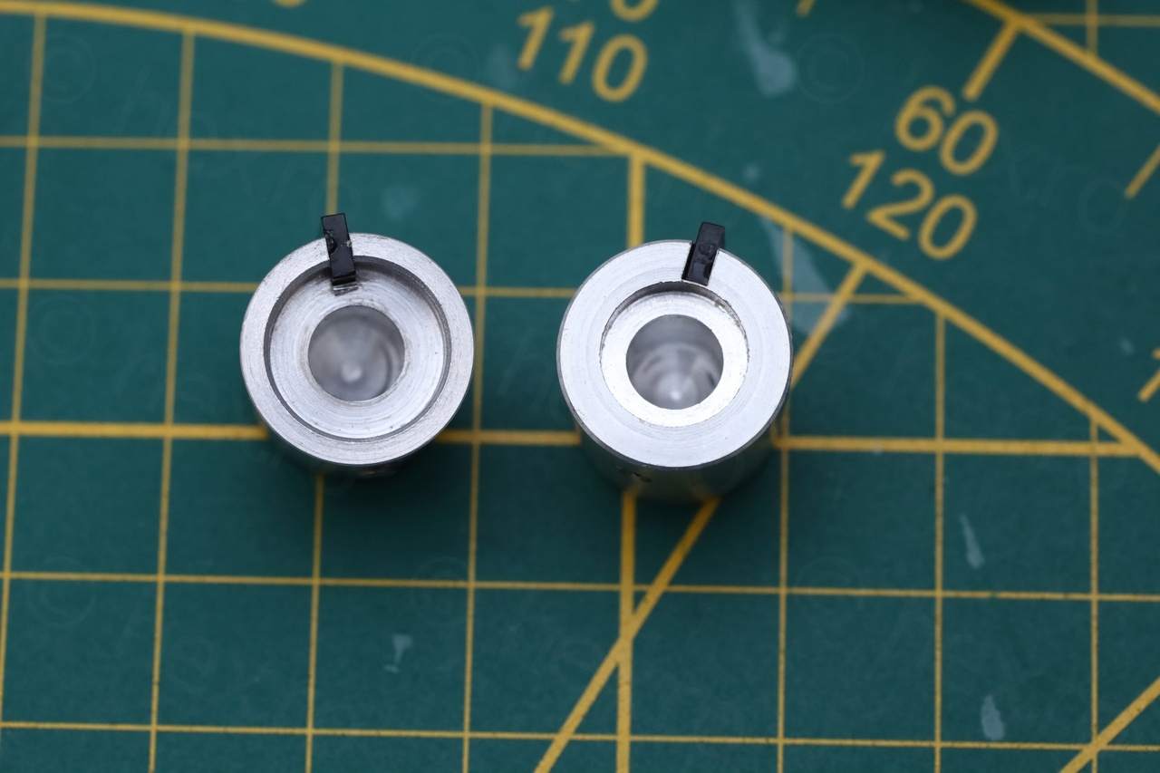
Ideally, the plastic would come out intact. But it was impossible. I left it in olive oil over night thinking that it may have been glued. Absolutely no change. Plastic was also thin, so any attempts to mechanically separate it would bend / break it. Thus, the only solution was to 3D print it:

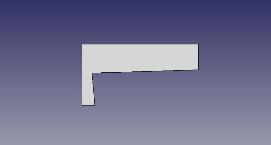
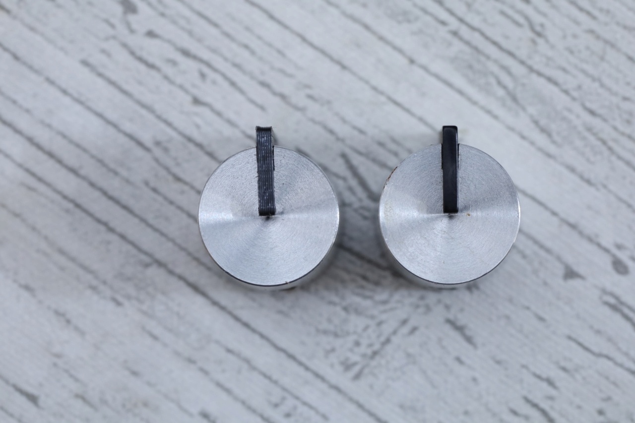
The trouble is that the shape of the plastic is not trivial, if one were to match the same angles as the original as well as the thickness to fit snugly it into the groove. But I got it as close as possible and unless you check very closely to see the printed layers – it looks real. I think the results would be much better with a resin printer, but I don’t have one yet. It is a reversible restoration, since no glue was used to hold the plastic in.
Opening up the turntable
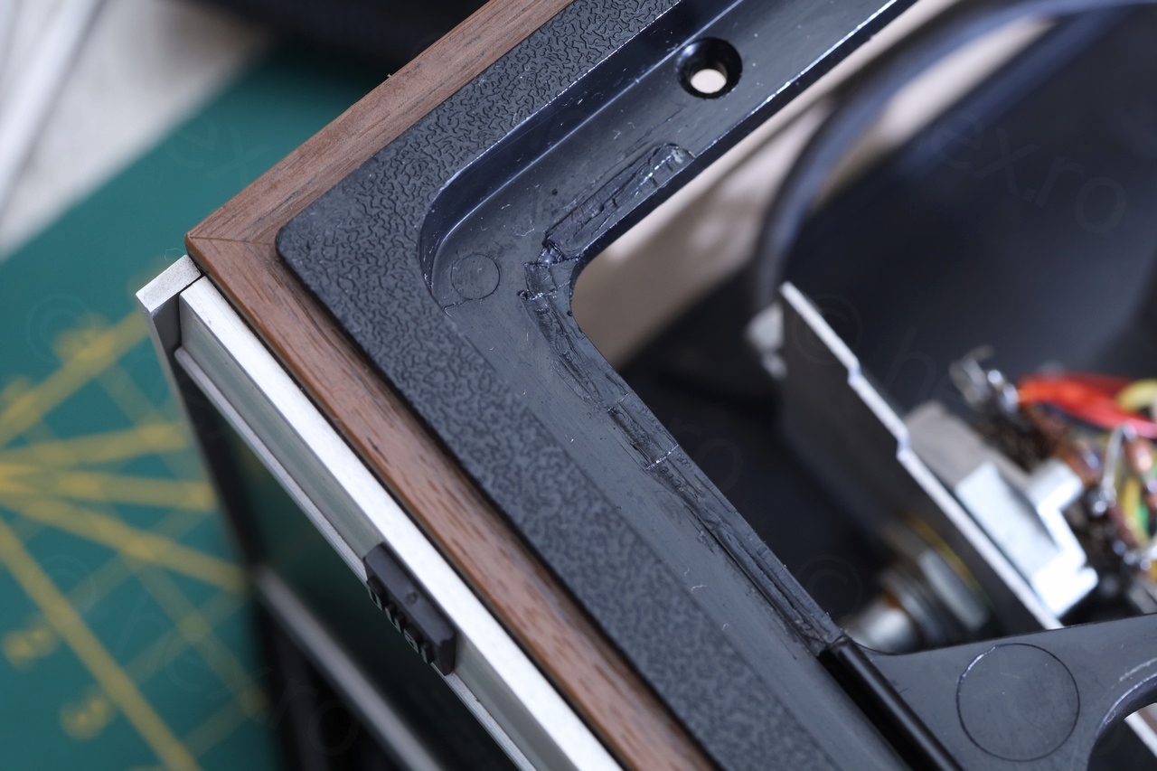
From the get go, this Kombi was puzzling. The Service Manual for Dual 1234 shows it being paired / sold with Dual HS132 amplifier. The Service Manual for Dual HS130 shows it paired with Dual 1224 turntable. But what I found was the Dual 1234 with the HS130!
The corner of the plastic ridge of the HS130 housing was flattened: but not sure if this was to fit the Dual 1234 on top:
The turntable was hard to lift from the case of the amplifier, since there is metallic C clamp that was going under the plastic hole in which the spring sits. And is tricky to keep the spring compressed (and out of the hole) while sliding the turntable to the left (lifting up is impossible do to the clamp that hooks under the ridge).

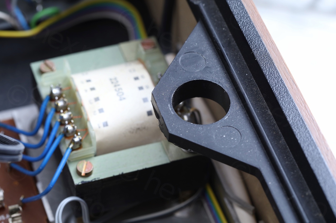
Except this inconvenience, access is easy and while the wires are long enough – be prepared to have some tall standoffs on which to sit the turntable while having access to the insides of the amplifier.


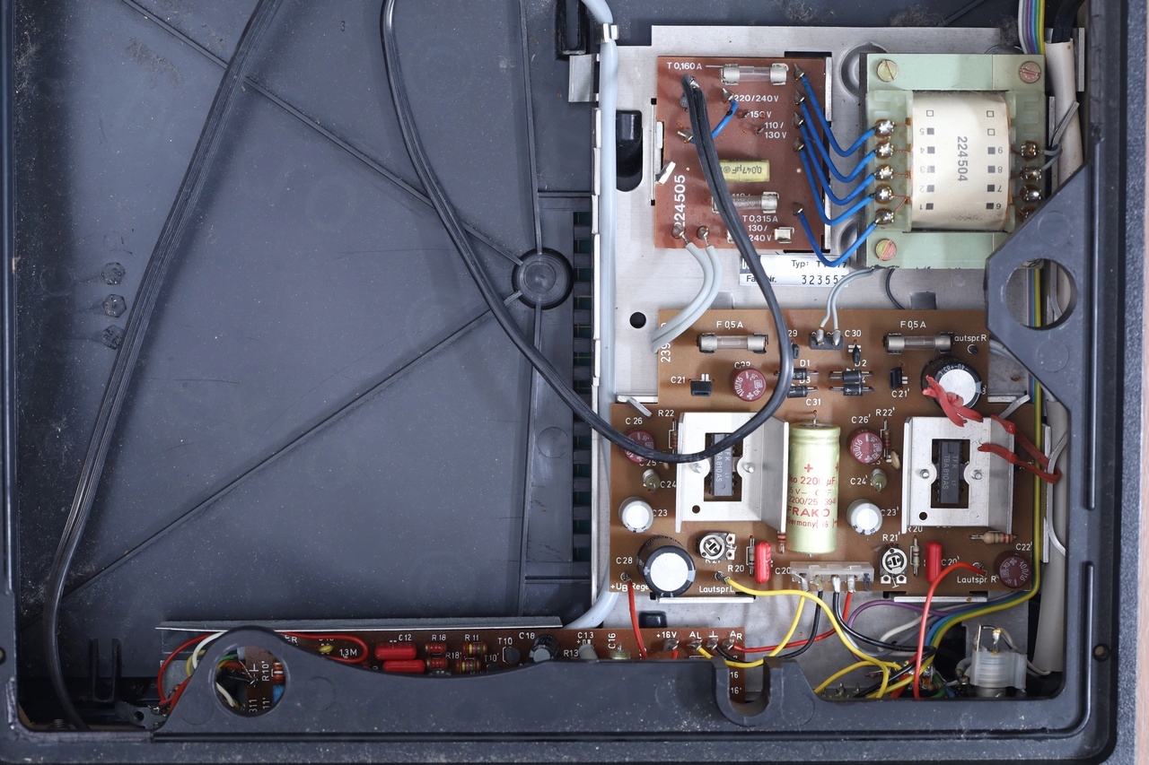
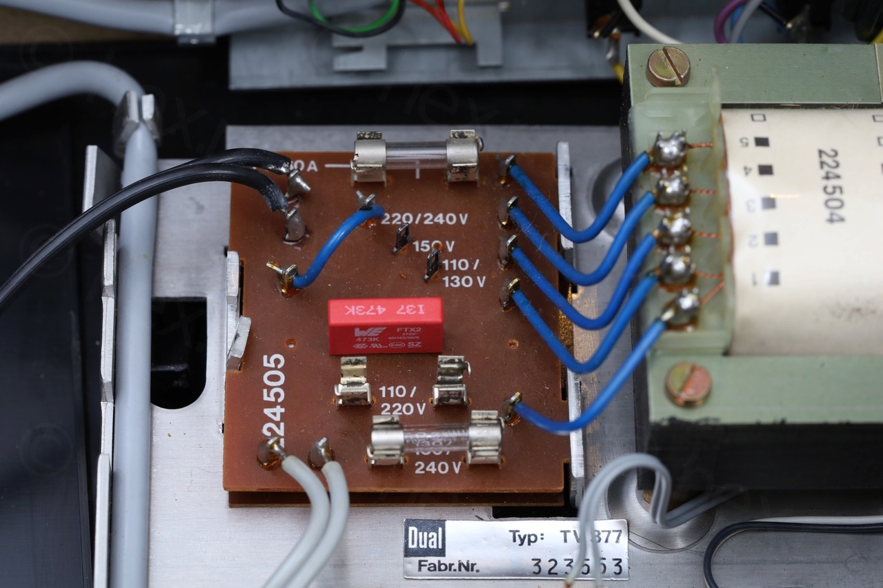
Replacing the RIFA capacitors
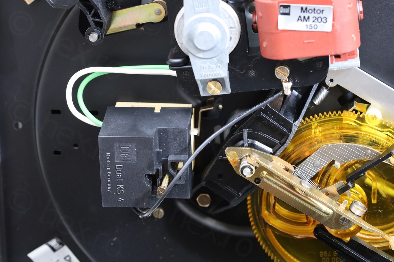
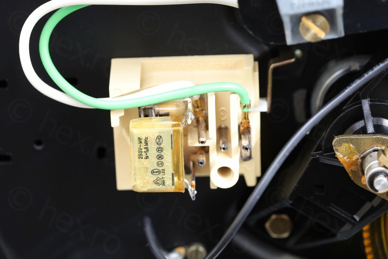
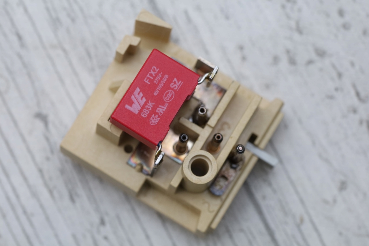
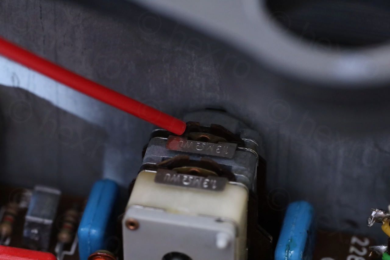
I spotted the RIFA capacitor on the power board. It was already cracked and bulged out, but not yet exploded. Reading online I found out there is another RIFA capacitor inside the Switch Plate (Dual KS 4). That one too was cracked but not exploded.


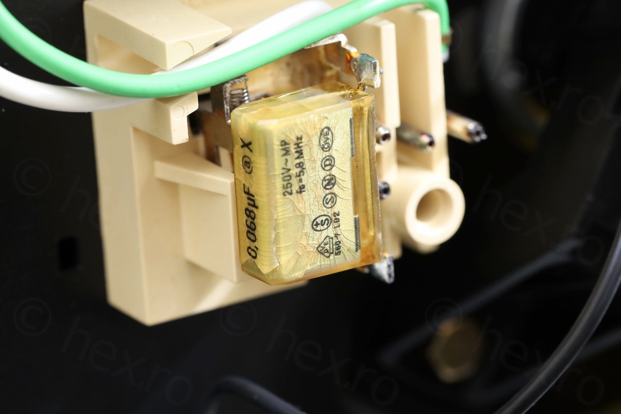
Initially I wanted to preserve the original look, but the modern 0.068µF that looks like the old one has a different lead spacing (20.3mm instead if 15mm) and is bulkier. Thus, I went with these two: 890324025009CS and 890324025013CS (WURTH brand). Both the 0.047µF as well as the 0.068µF have the same lead spacing of 15mm. I am not sure if the modern look-a-like would still fit, but I didn’t want to take any risk.


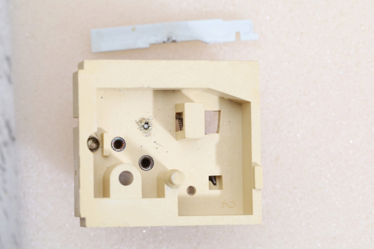
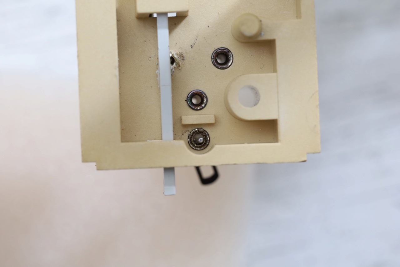
However, I encountered some issues while working on the Dual KS 4 board, where the pins on which the two wires have actually separated from the board.
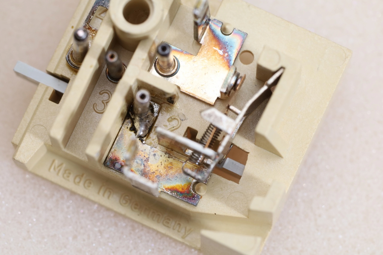
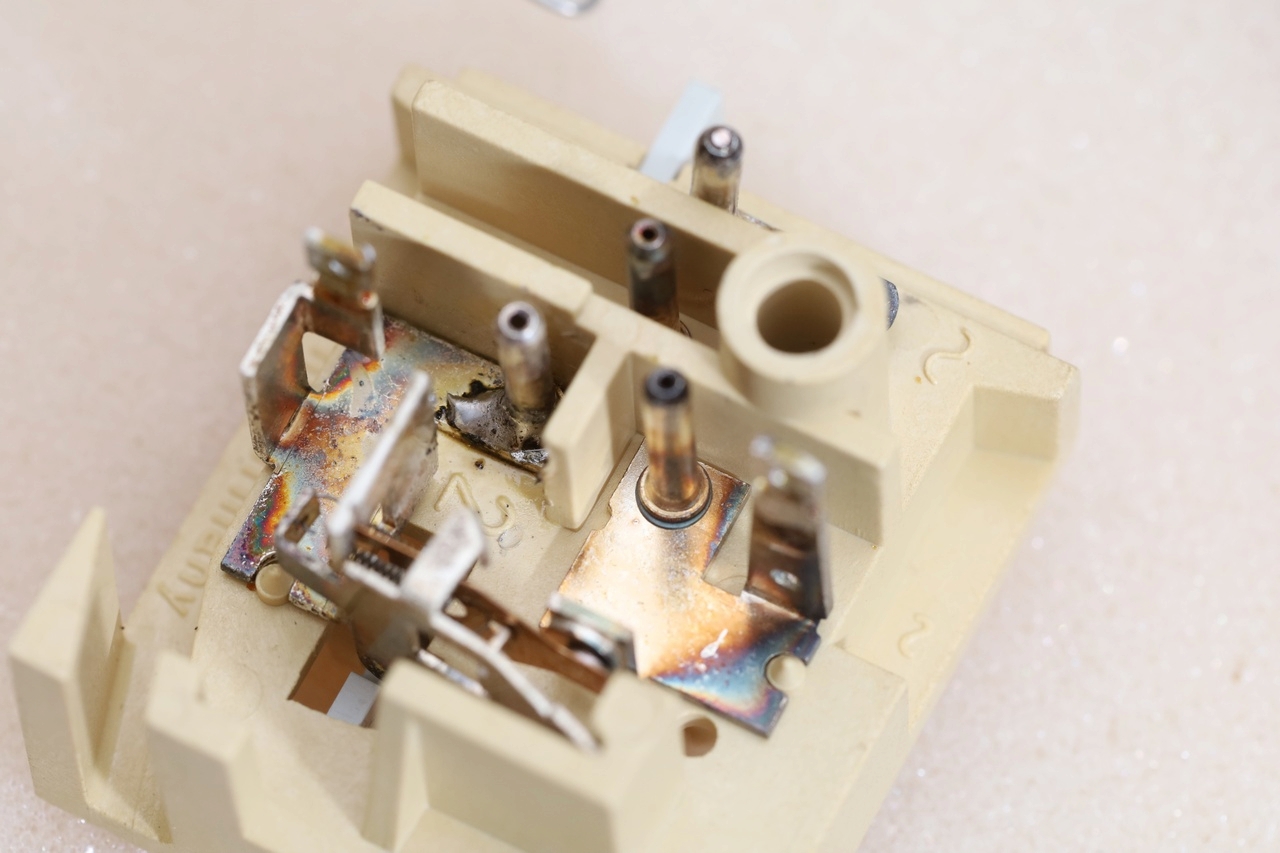
Rebuilding the Dual KS 4 module
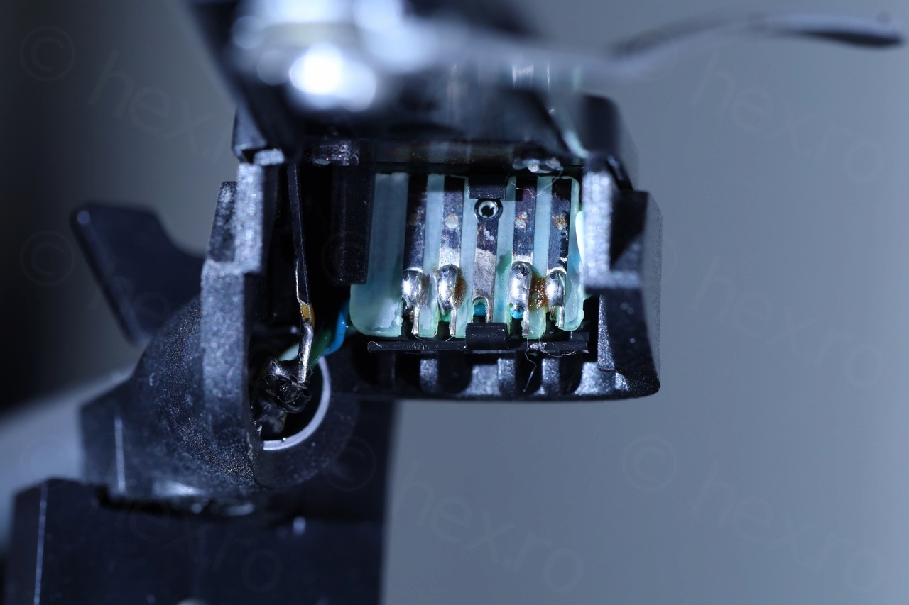
I didn’t initially want to take the switch plate out figuring out I can de-solder the safety cap with it still attached to the turntable. But while trying to de-solder, the adjacent pin (the one of the white cable) has separated from its metal support. Pfffff
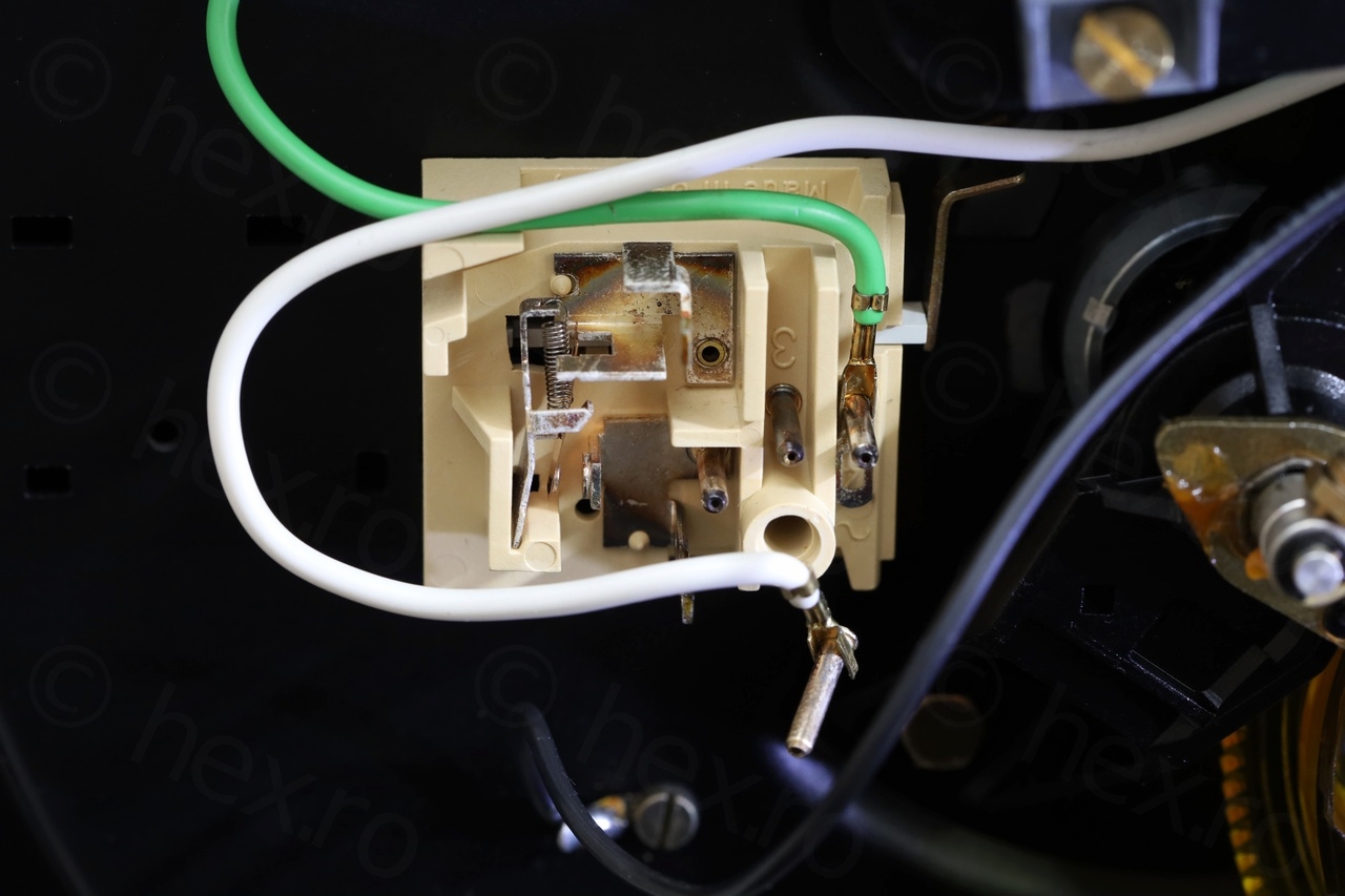
Believing that the temperature had something to do with it, I decided to do the right thing (since the same metal part holds both this white cable pin as well as one of the lead of the safety cap), I decided to take the board out. While taking the board out, surprise. The pin of the green cable has separated! And there is no metallic connection that was heated during the de-soldering.
This is a build quality issue – the switch plate is rather brittle.
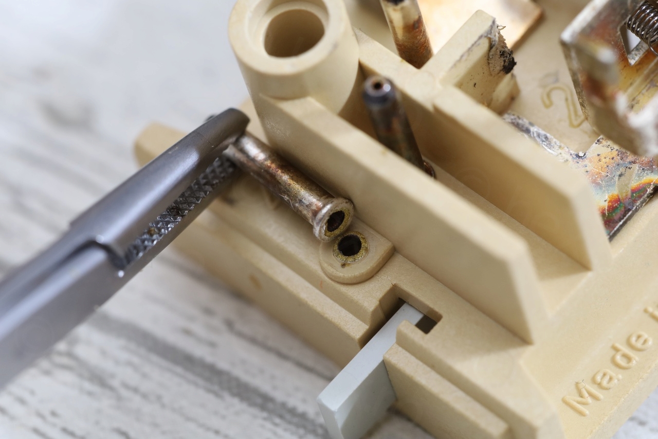
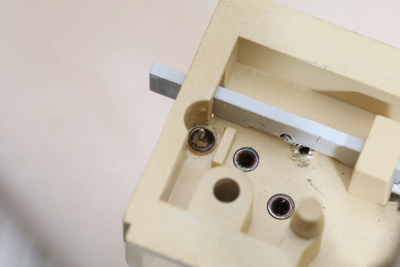
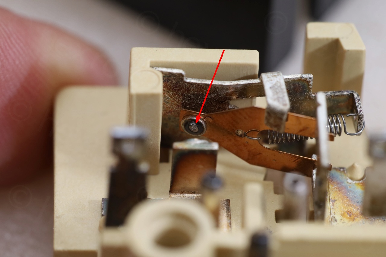
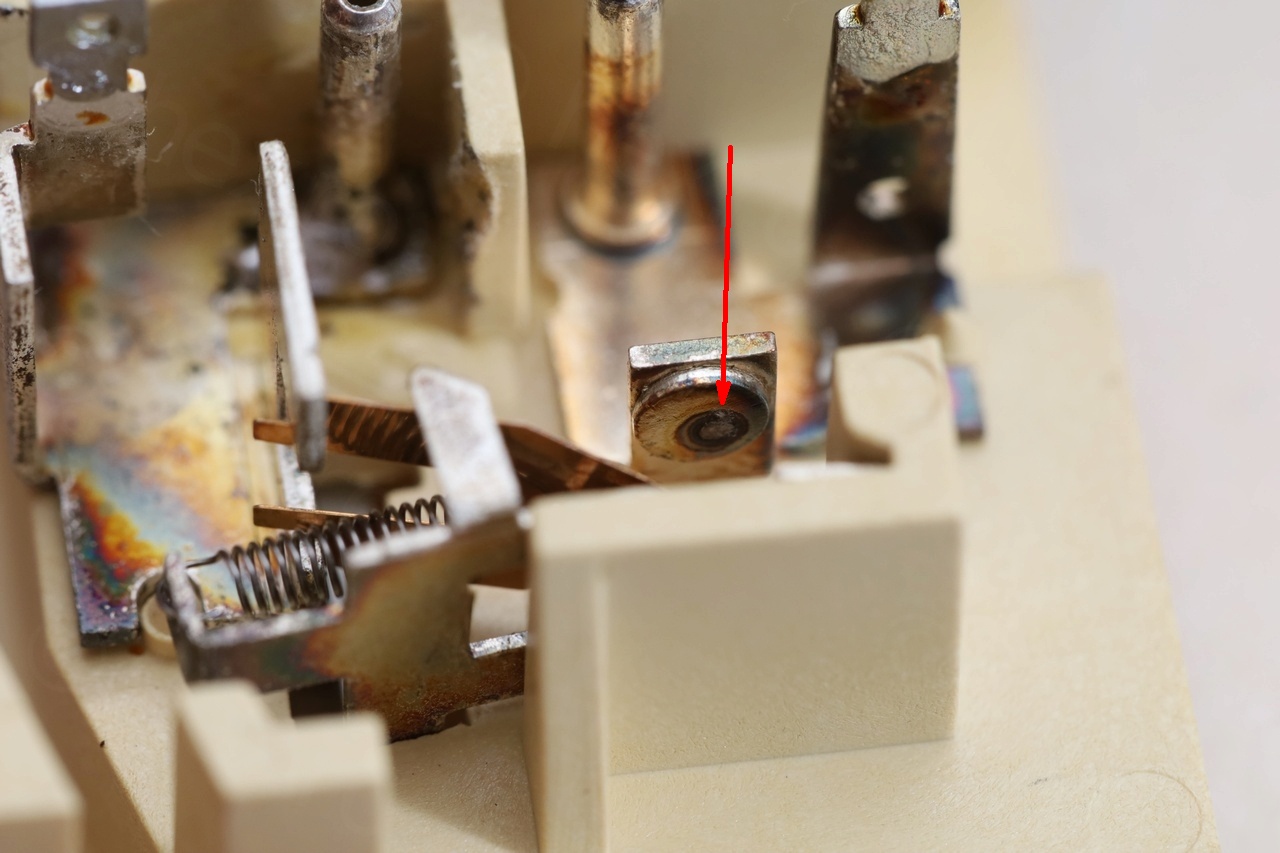
Taking the plate out, I figured it may be easy to just apply a bit of solder onto the bottom of the initial pin and solder it back onto its support. This was a mistake, as … by applying pressure onto the pin down towards the metal, I was inadvertently pushing the opposing metal part onto the plastic slider underneath.. Hard to express in words, hope few pictures will clarify:


I finally managed to dislodge the slider from where it melted and I took it out, after bringing the little lip into an extreme position to allow it to slide out. The slider is almost intact, I just needed a way to solder the pin without damaging the slider..
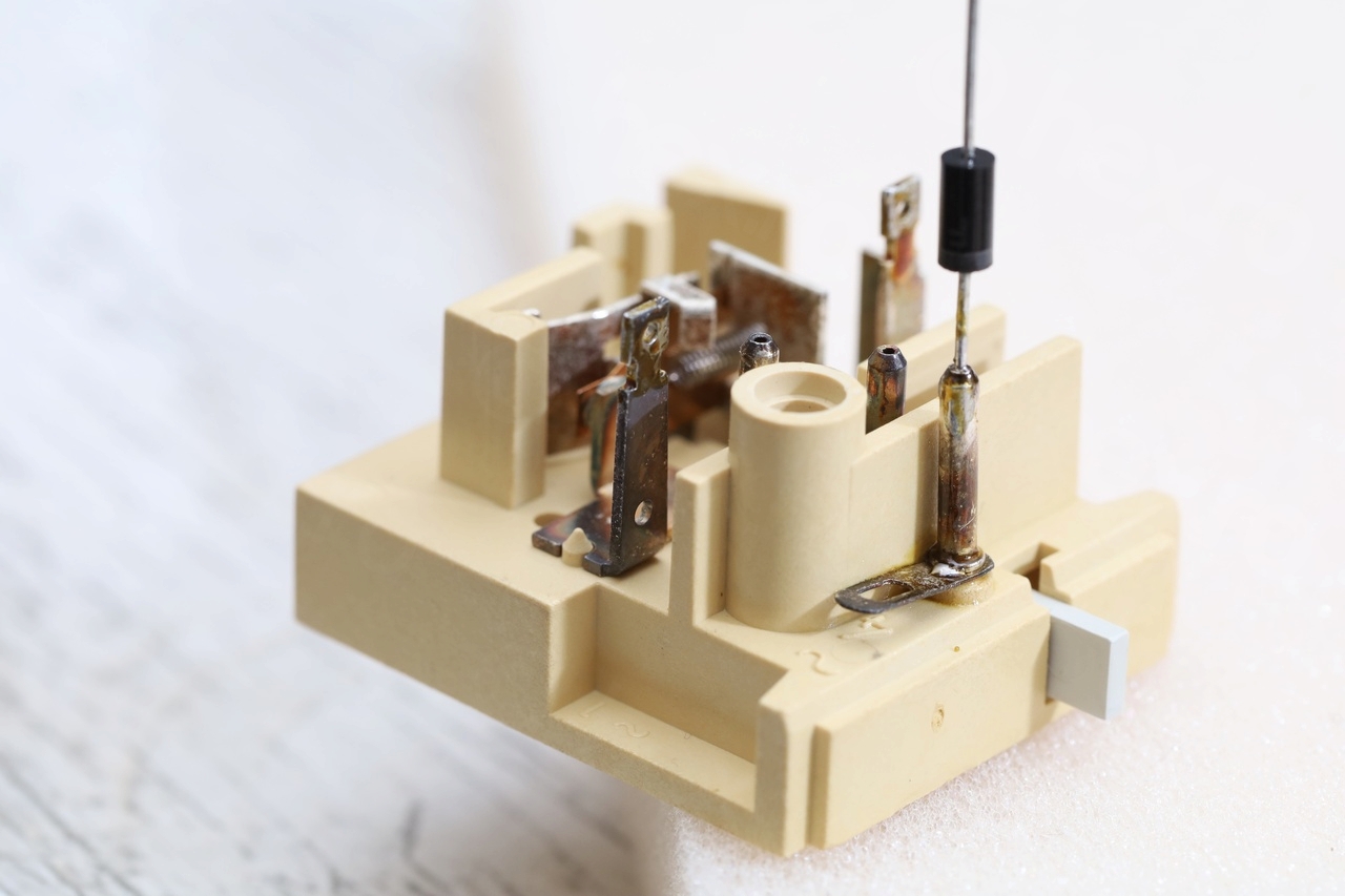
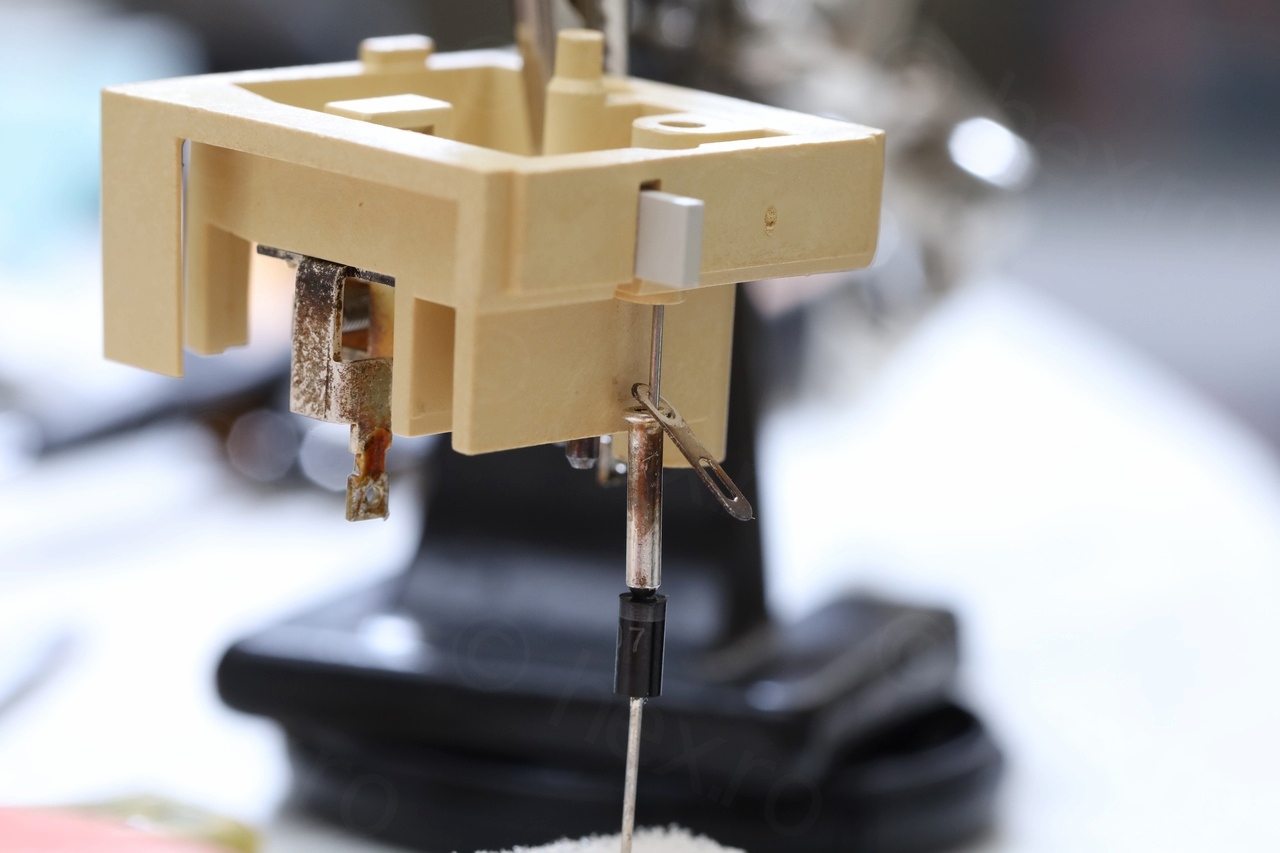
I got the idea eventually looking at the other pin that broke down. Using a diode as a donor for one of the leads, I was able to sandwich the pin and solder it both at the top and underneath:
It was too late to apply the same fix for the initial pin … too much heat already and solder went through. I just decided to solder it directly on the metal board:
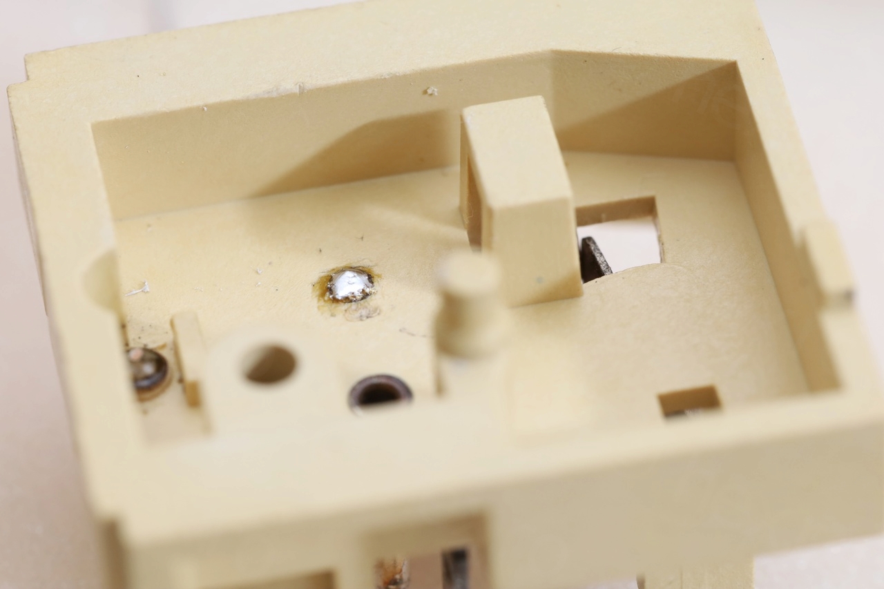
I feel bad… this is now a working module, but I should have not rushed with the first idea. Hopefully this will help somebody not making same mistake.
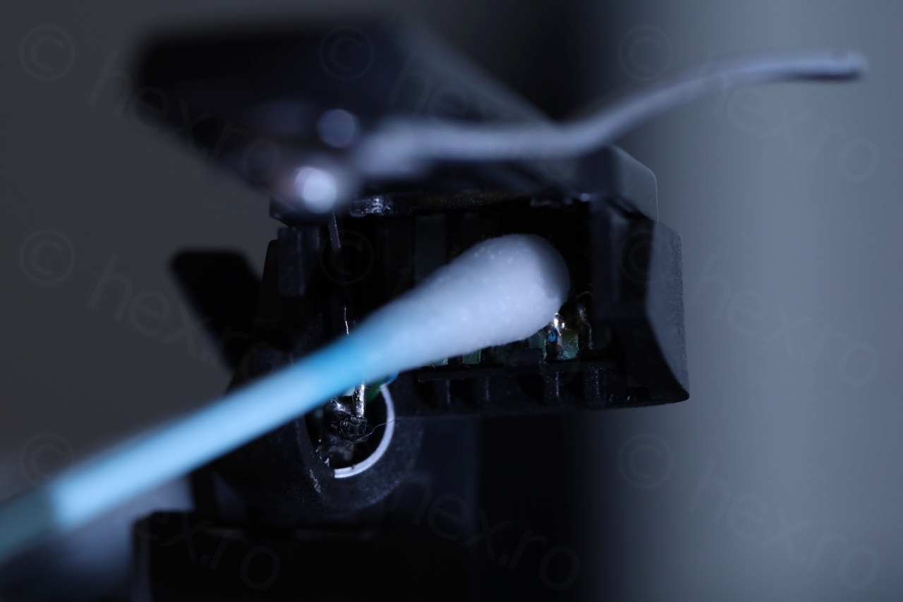
While I was on the board, I noticed a lot of oxidation on the switching contacts …
… which I decided to clean:
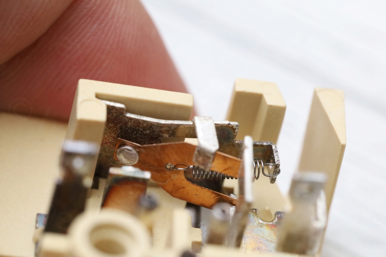

Now slider moves freely:
Final version before reassembly:
Steuerpimpel!
There was no Steuerpimpel of course, only the remaining crumbs of the initial one. And the arm still moved for a while, since those remains were still providing a tiny bit of friction:
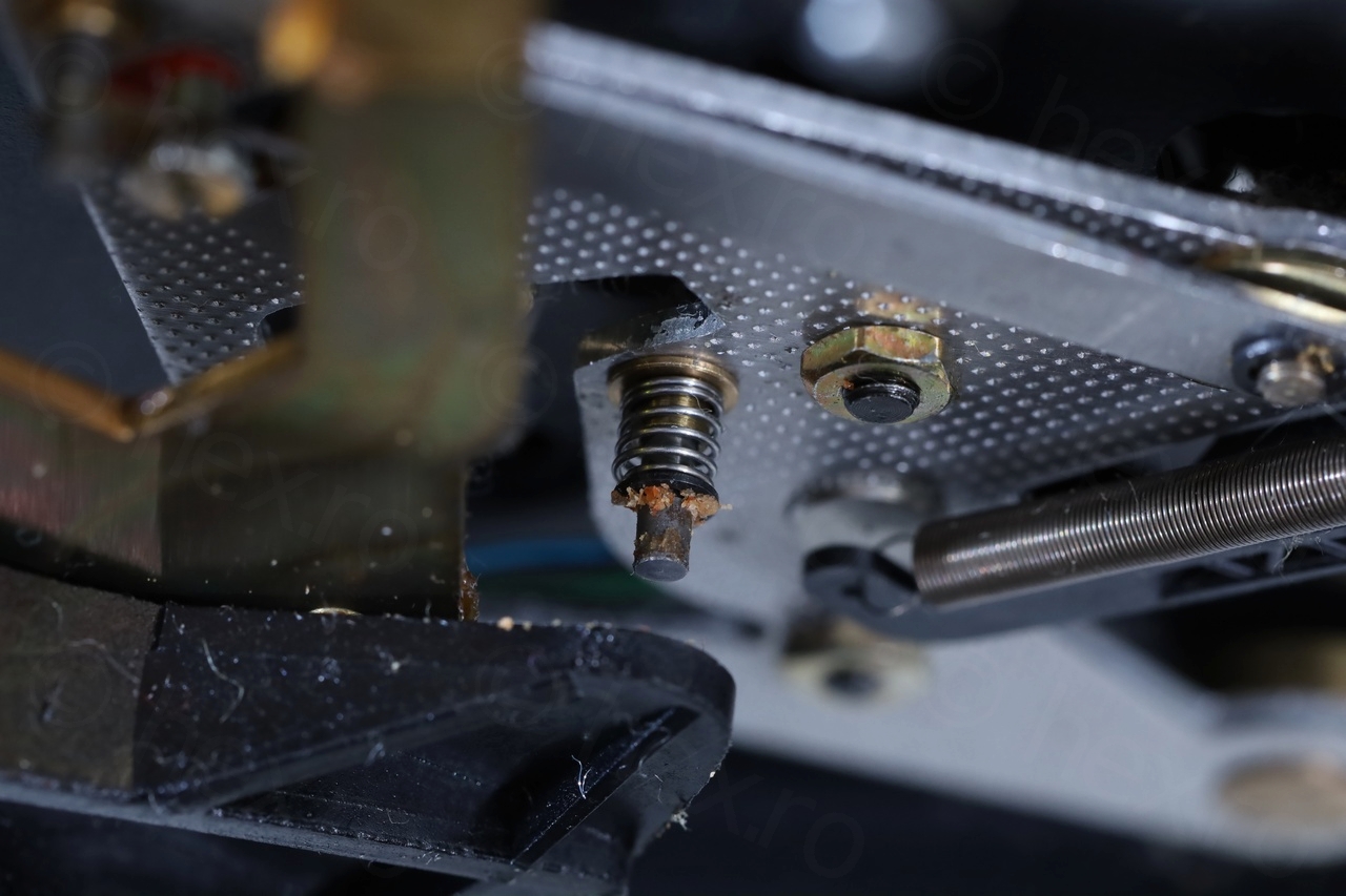
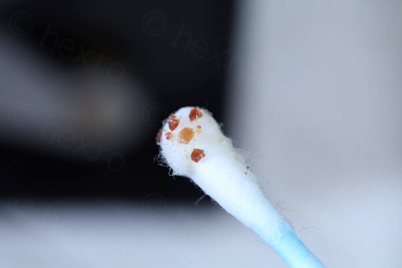
After the cleanup, no more friction / contact, and automated arm movement stopped:
I searched the web for Steuerpimpel DIY repairs, but ended up with people using three approaches: cut a piece of wire and use the sheath, a 3D print on Thingiverse OR order online a replacement. I didn’t have time to wait for the online part to arrive, was too eager to get it going. And I kept wondering where did I see this shape before (the little conical rubber) … where where where … I even remember using a similar small plastic as finger toy, but where did it come from ?!
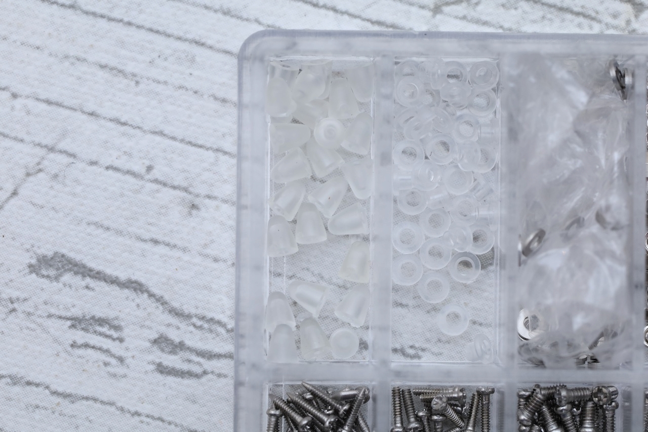
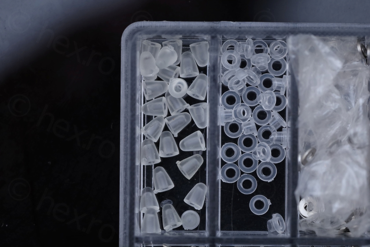
And I finally remembered… I used a piece of glasses screws to separate two electronic boards and the screw caps had the exact shape that these online Steuerpimpel photos looked like! I had a box full of Steuerpimpels 8-)!
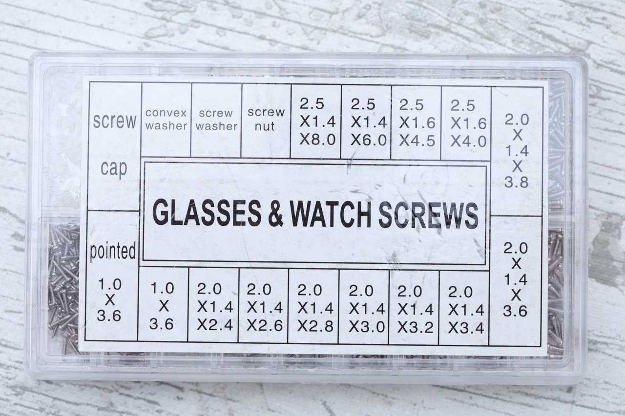
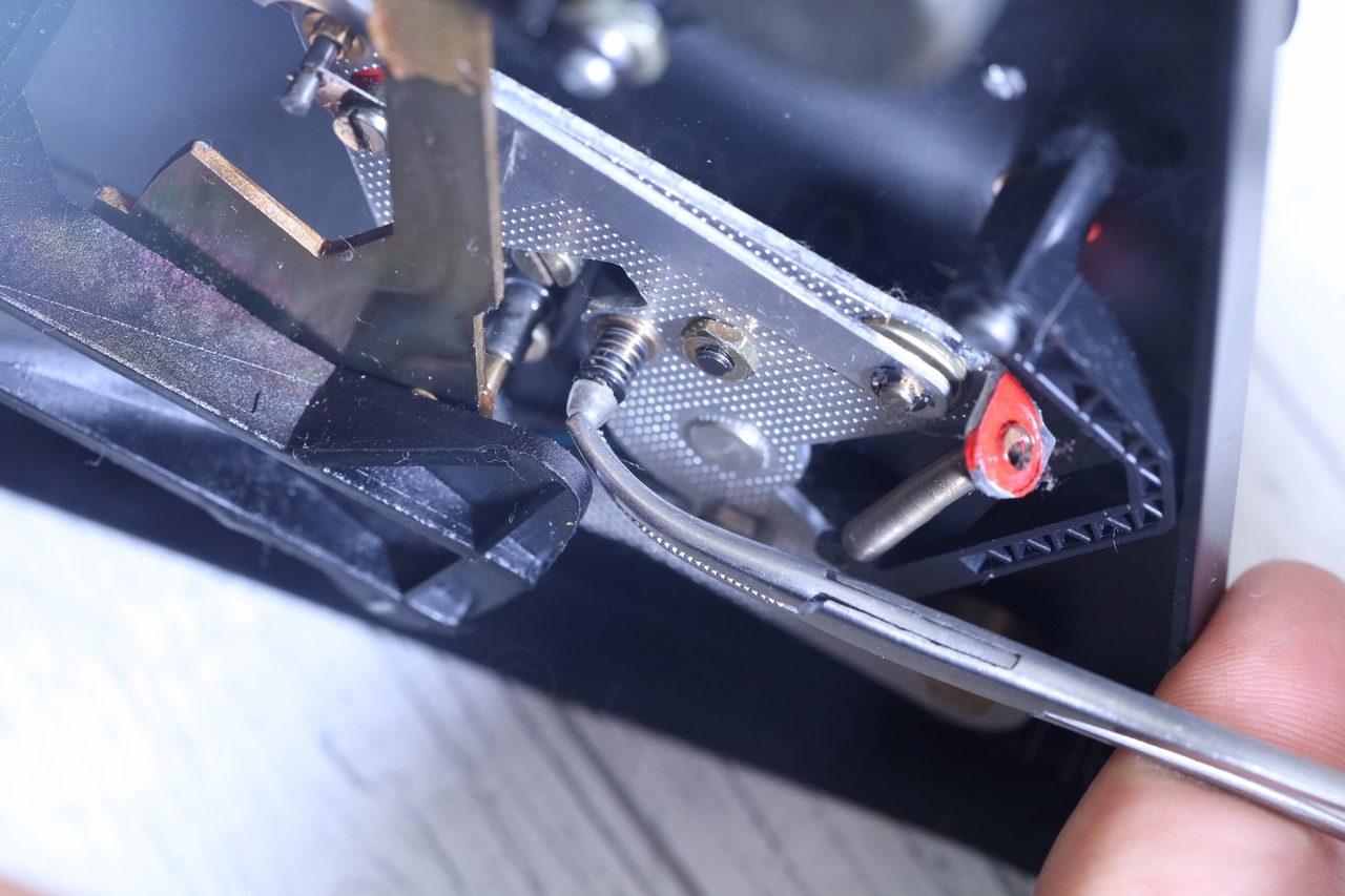
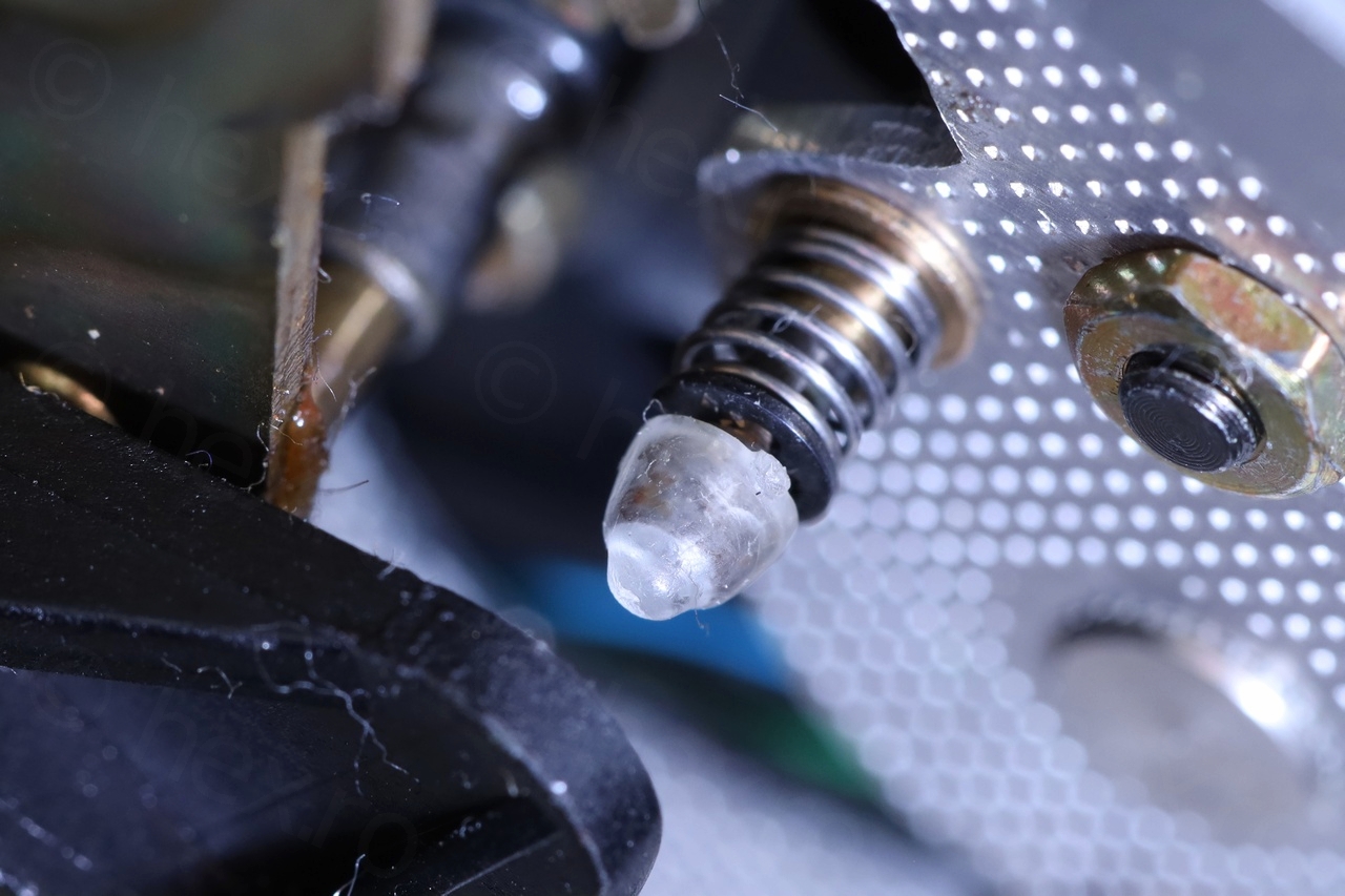
Used a curved pair of curved hemostat forceps to force it over the metal stud. The screw caps are the 1.4mm version (the inner hole) and they fit very very snugly over the stud. Very happy with the result. I nipped a bit from the rubbery tip, since watching the whole movement with it installed, it seemed it was a little too much compression on it.
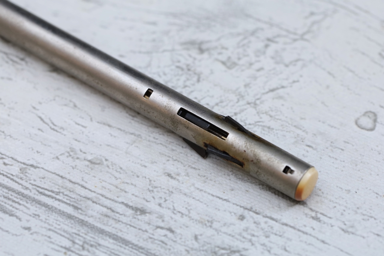
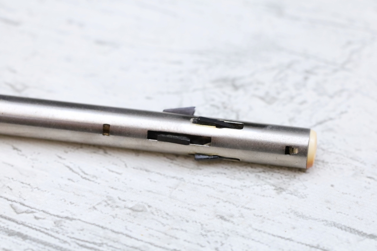
Dual AW-3 Stacking Spindle
While reading about the turntable, I found part of the original accessories was a Dual AW-3 stacking spindle. I got curious. This Kombi didn’t even have the place where to store it (there would be a place if I would have found it paired with the Dual HS132 amplifier).
But it was a saga to get one and ended up with two. Total price 34€ (one was 24€ from ebay, the second one came from a local electronics repair shop for 10€). Below, the one from the local electronics repair shop… the guy also buys equipment from the fleamarket which he tries to repair and sell. He happened to have an abandoned Dual.


The nice thing was that when I had a look at the Dual he took it from, I also spotted something else! That broken Dual HS27 also had the light guide that was missing from mine! I insisted badly I want the light guide – but the seller was reluctant, he still hoped he could salvage the amplifier. Said if he finds another one, he’ll sell it for 5€ .. I offered 10€ just to have it and surprise, the seller agreed – saying “if money isn’t the best motivator, what else ?!”.
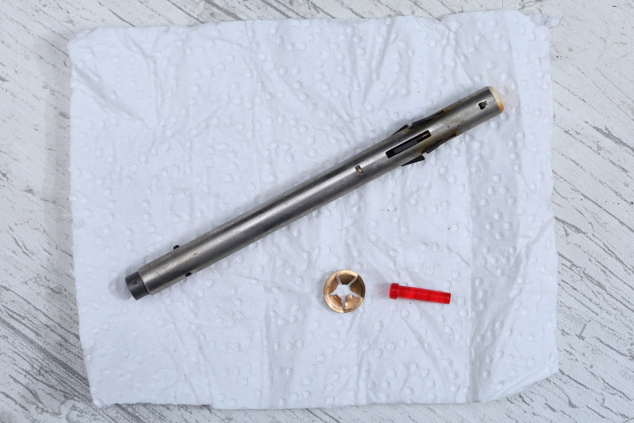
The Dual AW-3 was dirty and very hard to compress. And it did not drop the record at all. I did a through cleanup (Isopropyl Alcohol) and oiled it a bit and it started working better. Meanwhile, the second Dual AW3 arrived from ebay, and that one is way easier to compress and works. They look different a bit (at least at the bottom side).
Here is a video with the startup action, after having installed the Steuerpimpel:
Dual Amplifier Light Guide
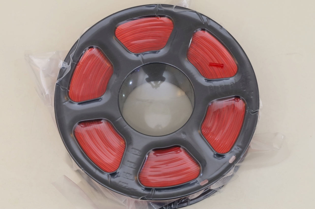
Finding a replacement Light Guide was very difficult – almost nobody mentions it online. I knew I will have to 3D print it, so I ordered a translucent red filament, and I had looked at many online photos to try and figure out possible dimensions. This turned up to be a bad idea, once 3D printed, the translucent filament loses a lot of its transparency …
Before finding the original at that old electronics repair shop – I even started to try to break down an existing 5mm LED to which I was about to attach a little part of the translucent filament.

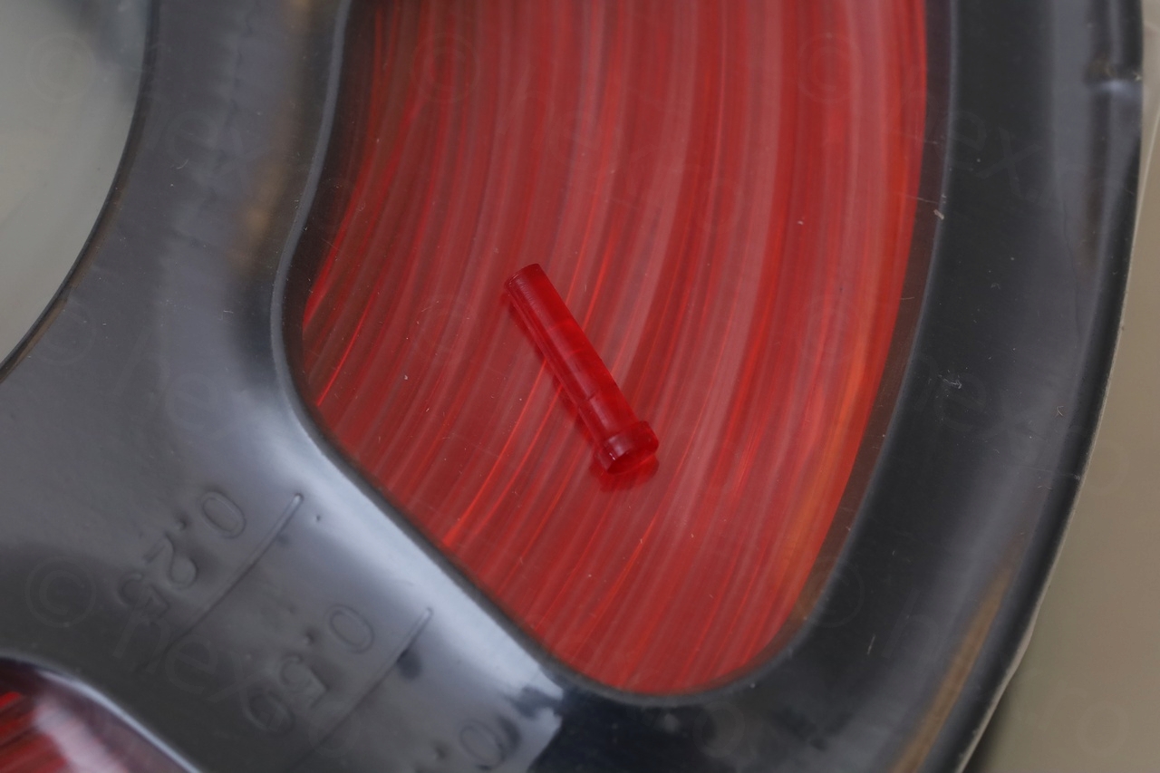


It was taken from a HS27 amplifier.
The original dimensions are:
- 2.7mm diameter of shaft
- 12.2mm length of the shaft
- 3.8mm diameter of the round tip outside the case
- 1.9mm height of the tip
I overpayed 10€ for the original light guide, 28€ for the filament which was not needed afterall.
Unbalanced Output
Since the turntable started to be usable, I realized another problem. The left channel was weaker that the right channel.
It seems that there are 2 schematics for the Dual HS 130 – one with Germanium transistors and one with the TBA641 B 12. But surprise, mine has the TBA810 AS ICs:
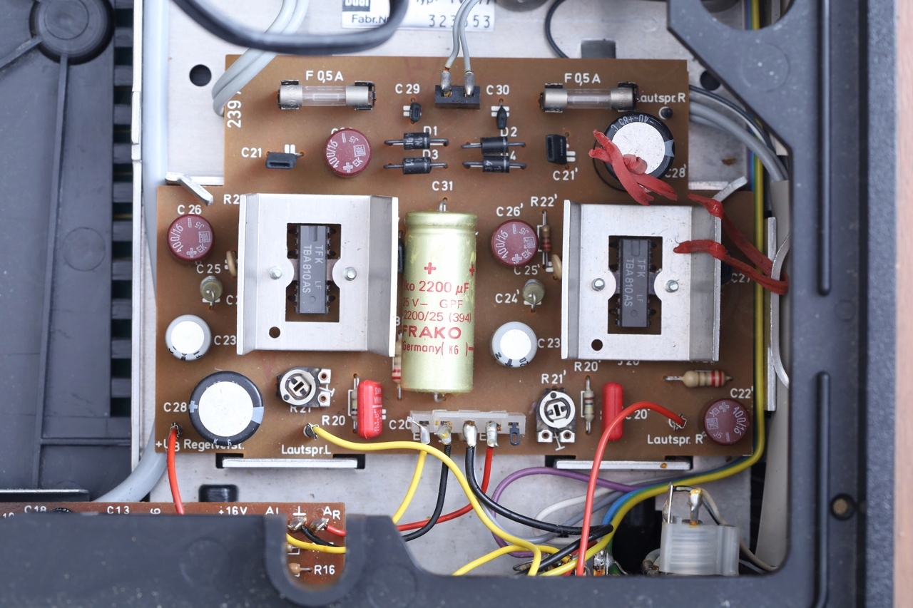
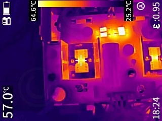
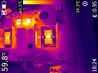
The only thing I could check were the two adjusting potentiometers – but first I was curious to see if something overheats on the boards. After 15 mins at max power on two 4ohm dummy loads – the right channel IC was a little hotter – 2C hotter – but nothing else suspicious,
To make it a little more precise, I hooked up the oscilloscope on the dummy loads – purple channel is the Right channel, and the yellow is the Left channel. Turntable was set to Mono – so the signals should have same output power:
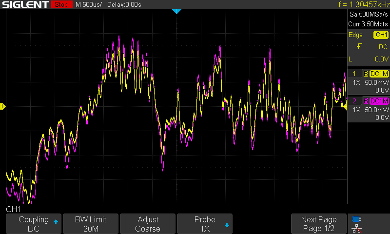
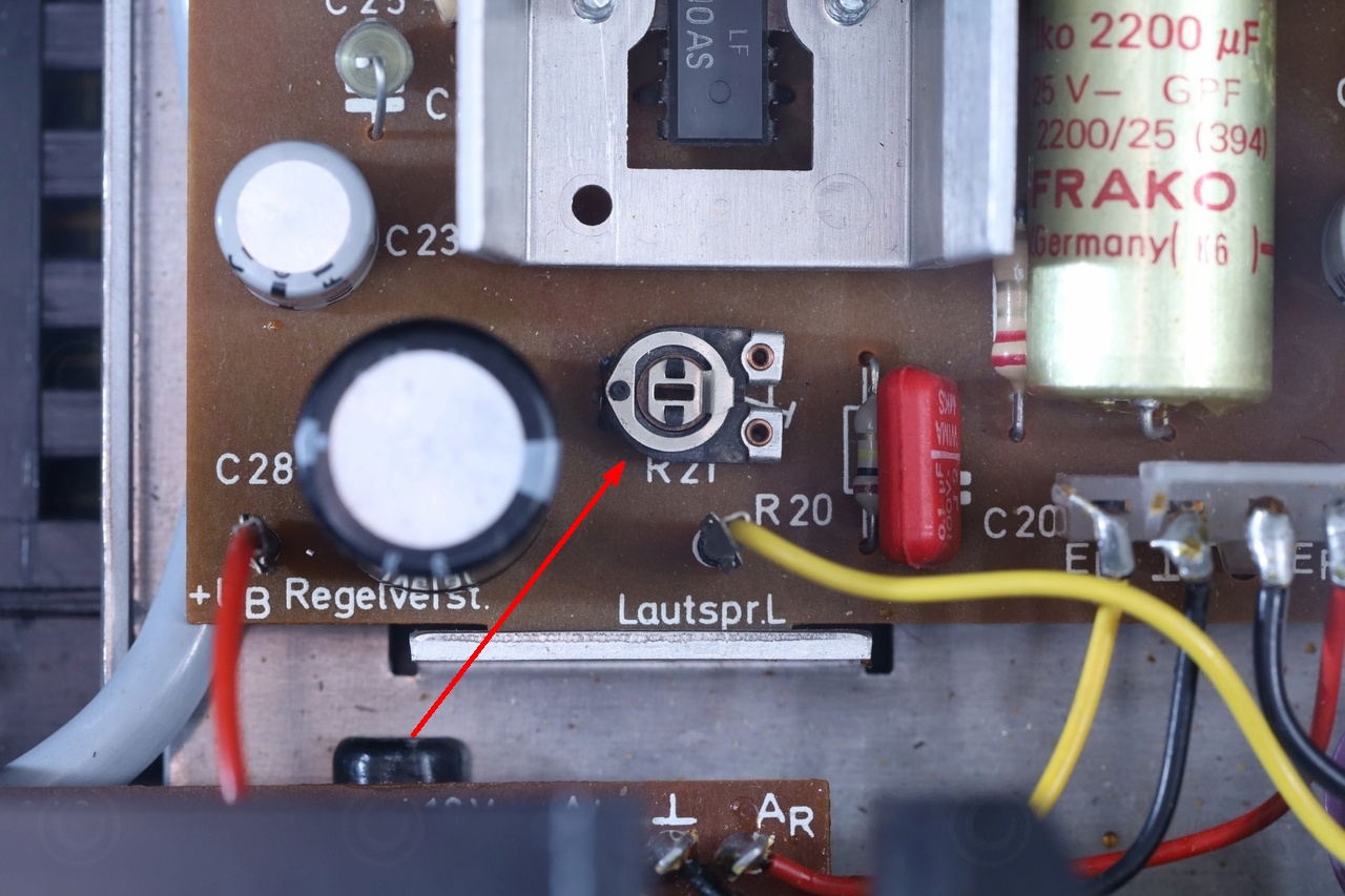
I adjusted the corresponding potentiometer (R21 on the board) until the channels mostly overlapped:
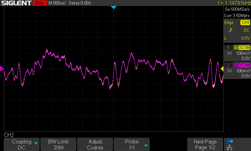
And indeed, this sorted it out. I can’t seem to get it to overlap 100% constantly, there are still some small differences on the output signal, but audibly they sound equal now.
Miscellaneous
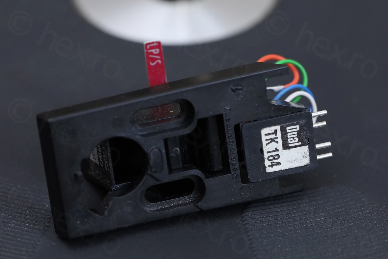
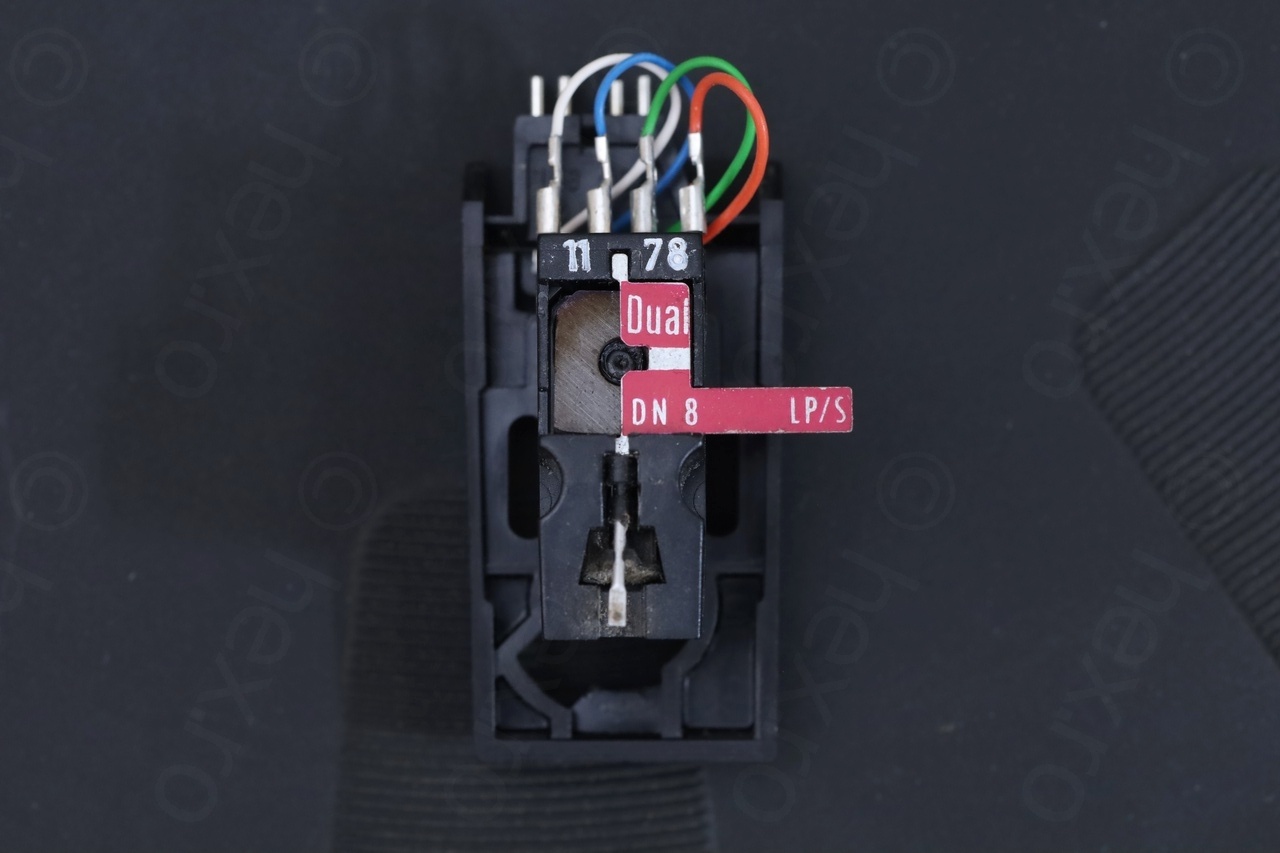
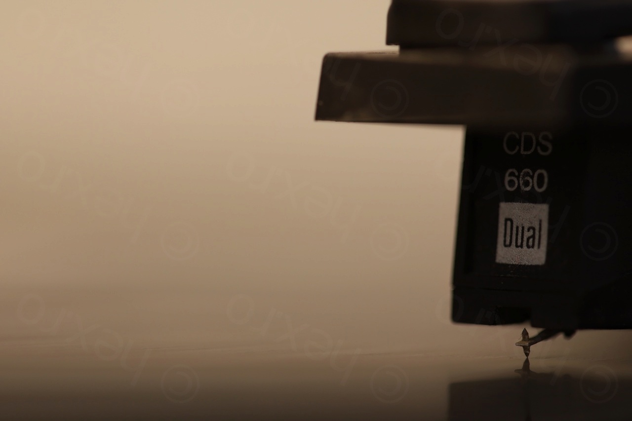
Few more maintenance steps were to clean the dirty idler wheel, flood the potentiometers with contact cleaner (they were scratchy) and scrub the contact pins of the cartridge.


I did not swap any of the electrolytic capacitors, their ESR was still fine. Nor re-greased the turntable – since everything seemed very smooth and quiet.
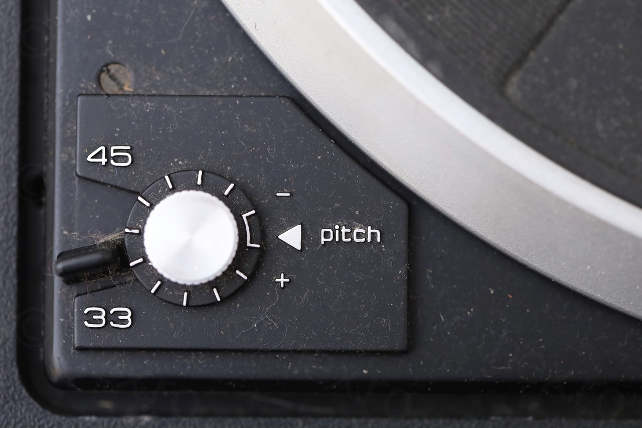
The speed control is not perfect though – I had to fiddle with the coarse speed adjust screw – as even with Pitch at minimum turntable was still fast. There is a coarse speed adjust screw very close to the Pitch control, and I was able to slow down the table enough. However, if I check again after 30 minutes for example, it becomes slightly faster, or slightly slower. I think it is good enough ..
Forgot to mention: I moved the fuse to the 240V position (~235V at the plugs).
Few more photos:

Leave a Reply