


Introduction
Restoring this mini CRT took effort, and energized by the success (and a very detailed service manual), I decided to try to use the Oscilloscope for the first time to see the Video signals on the driver board.
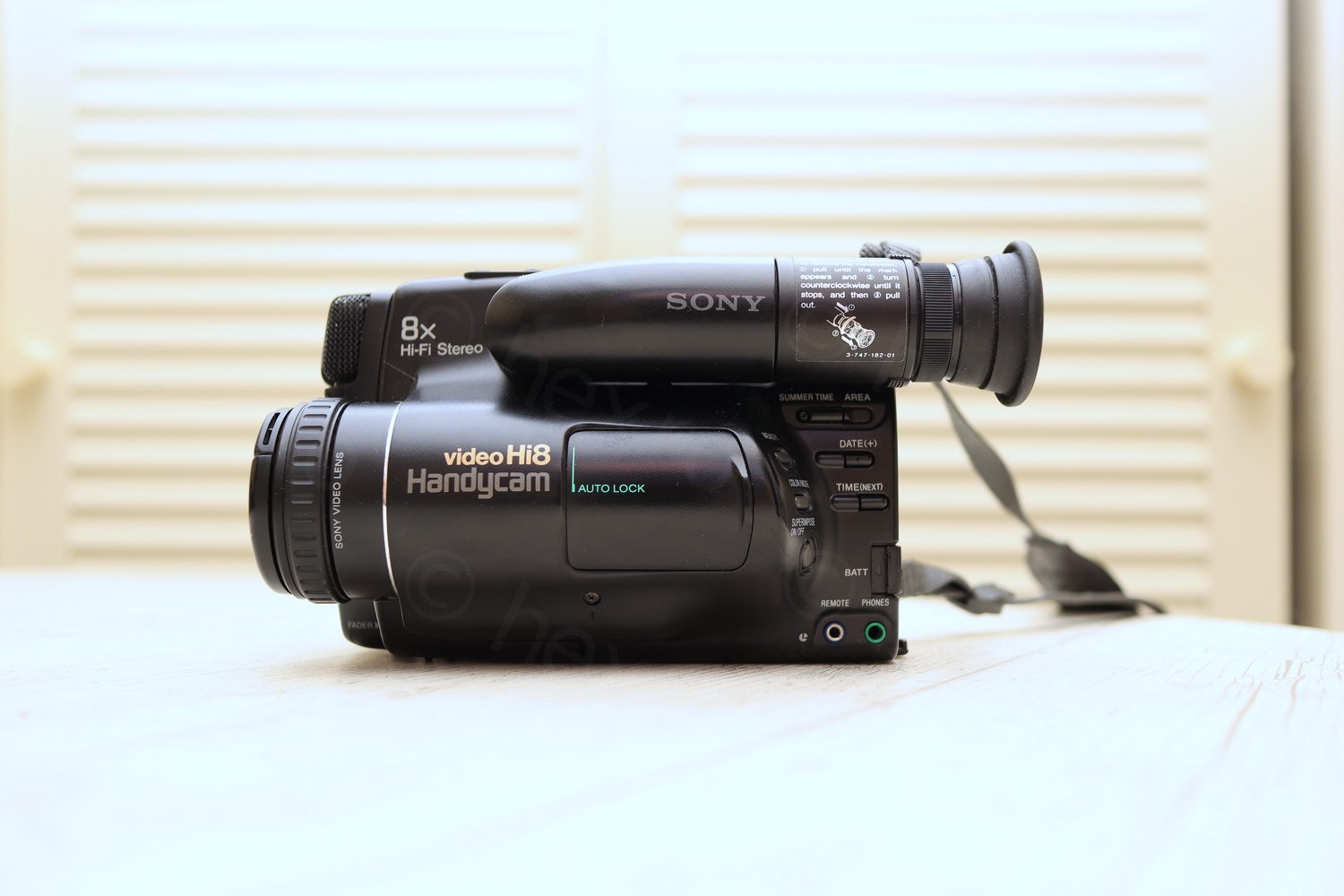
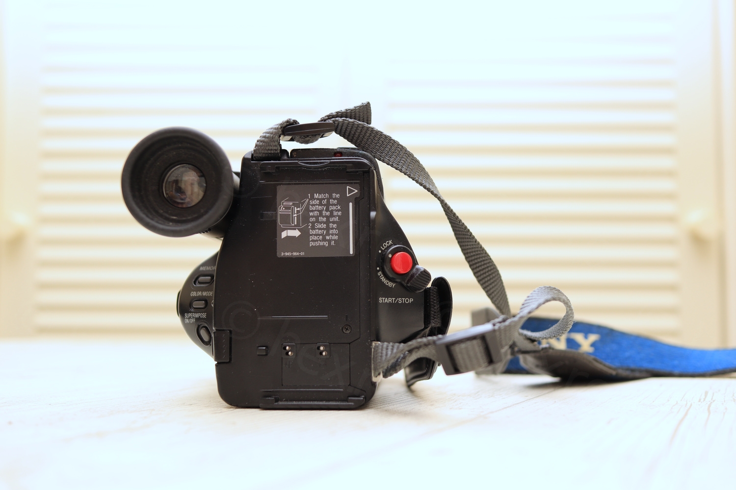
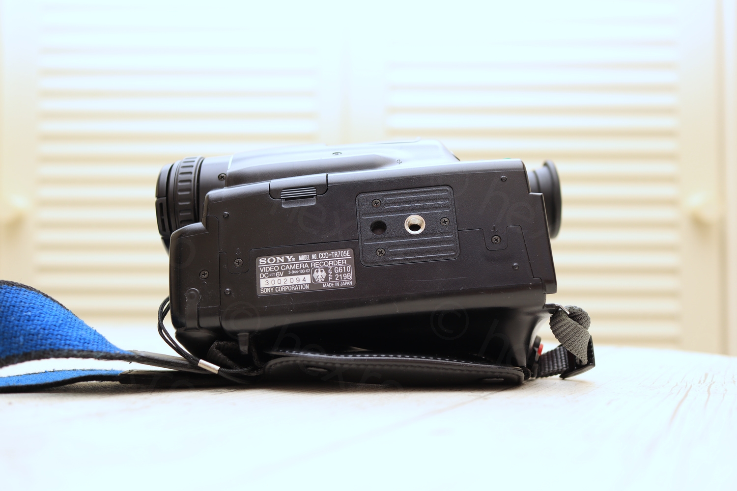
I found this CRT inside a Sony CCD-TR705E camcorder that I bought at a flea market.
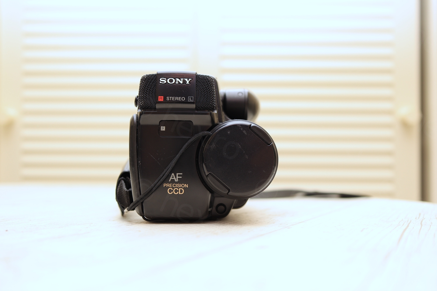
Camera presentation
The camera came without batteries and seemed rather clean, but the top plastic cover over the tape tray was very sticky and started to deteriorate.
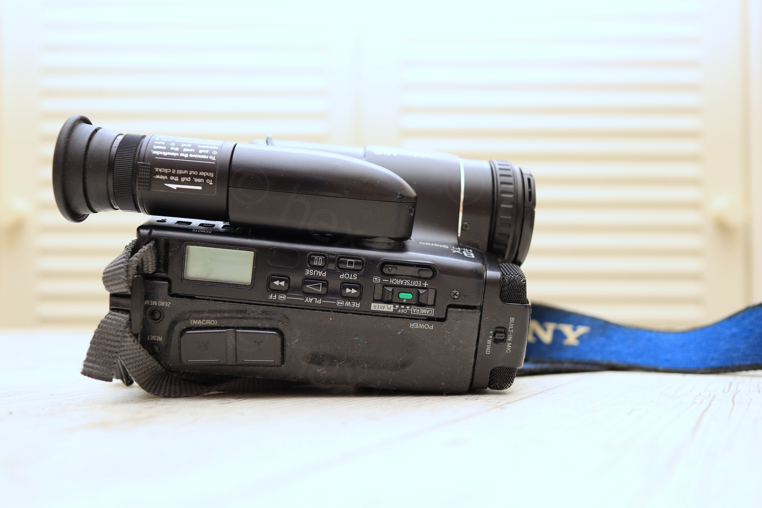
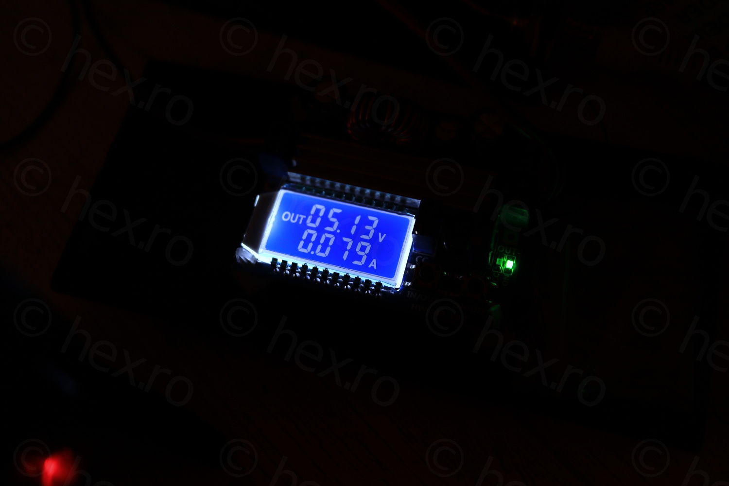
I have tried to power it with an adjustable power supply, but except the LCD that was flashing 00:00:00, nothing else worked. This had me worried, as usually, it is not a good sign, but I was hoping maybe the Electronic Viewfinder unit would still work independently.
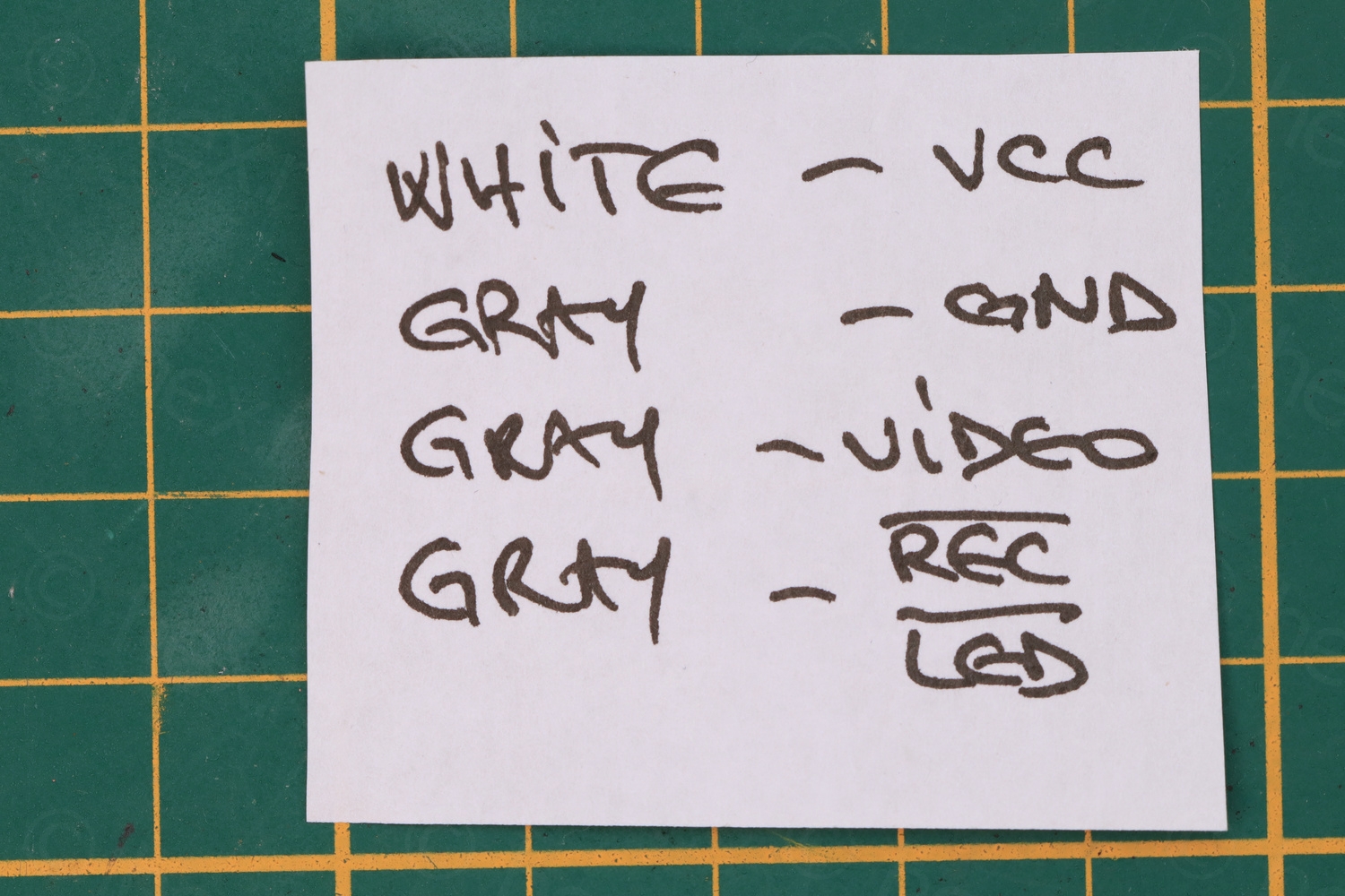
Upon opening up the camera, first good news – EVF unit has only 4 control wires, which should simplify identifying which one is VCC, which one Ground and which one Video IN.
Sticky flap cover 
Difficult to open 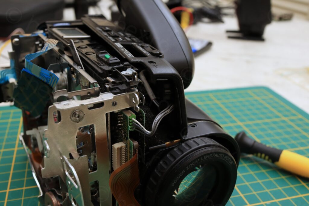
EVF – 4 wire connection 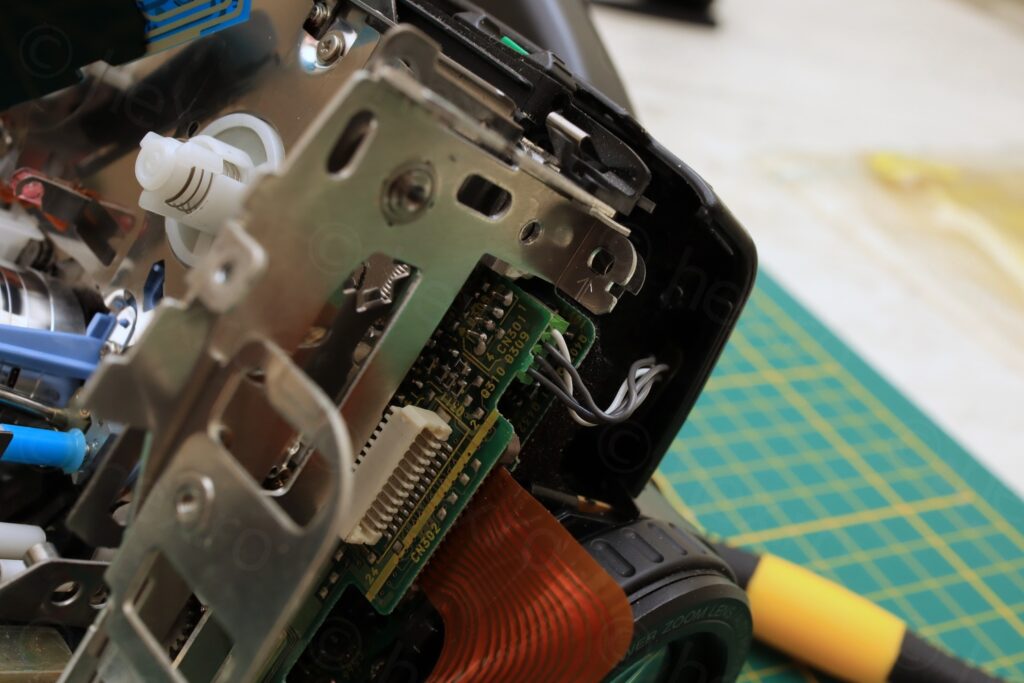
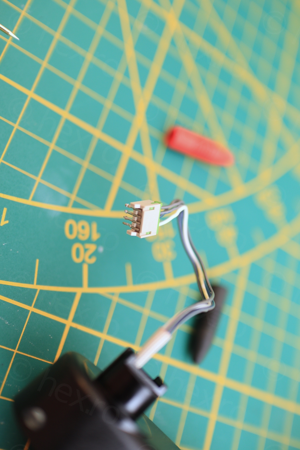
Closeup of EVF plug 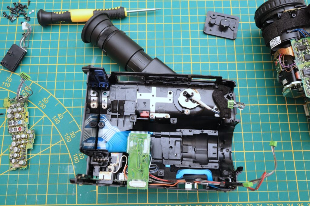
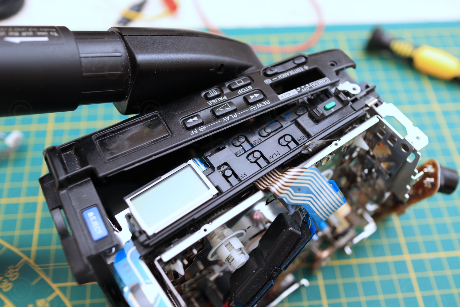
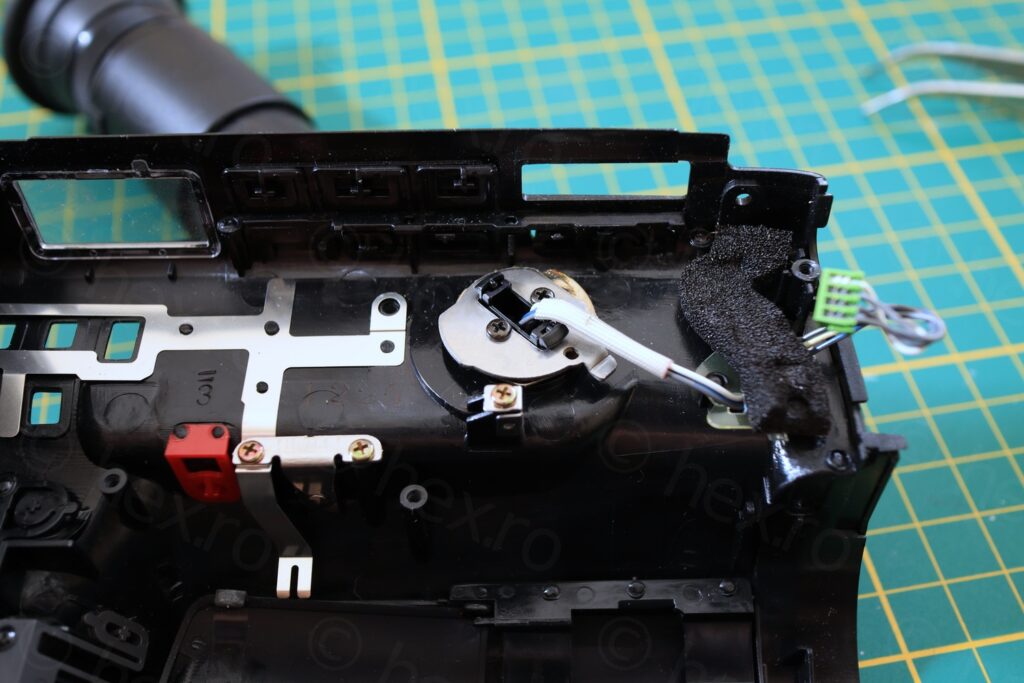
EVF attached to main body 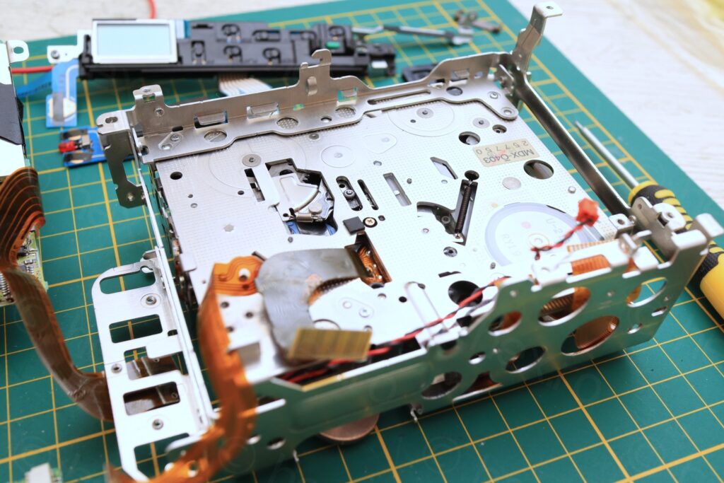
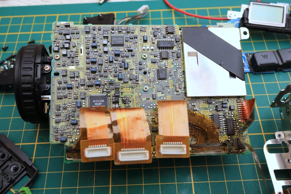
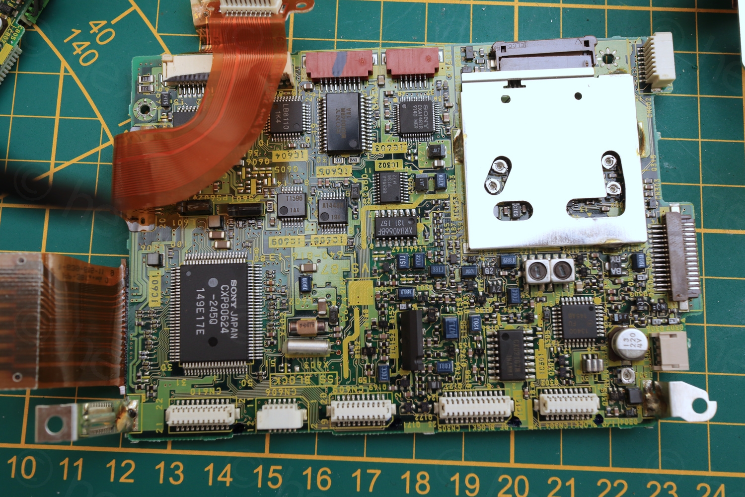
Motherboard overview 
Motherboard overview


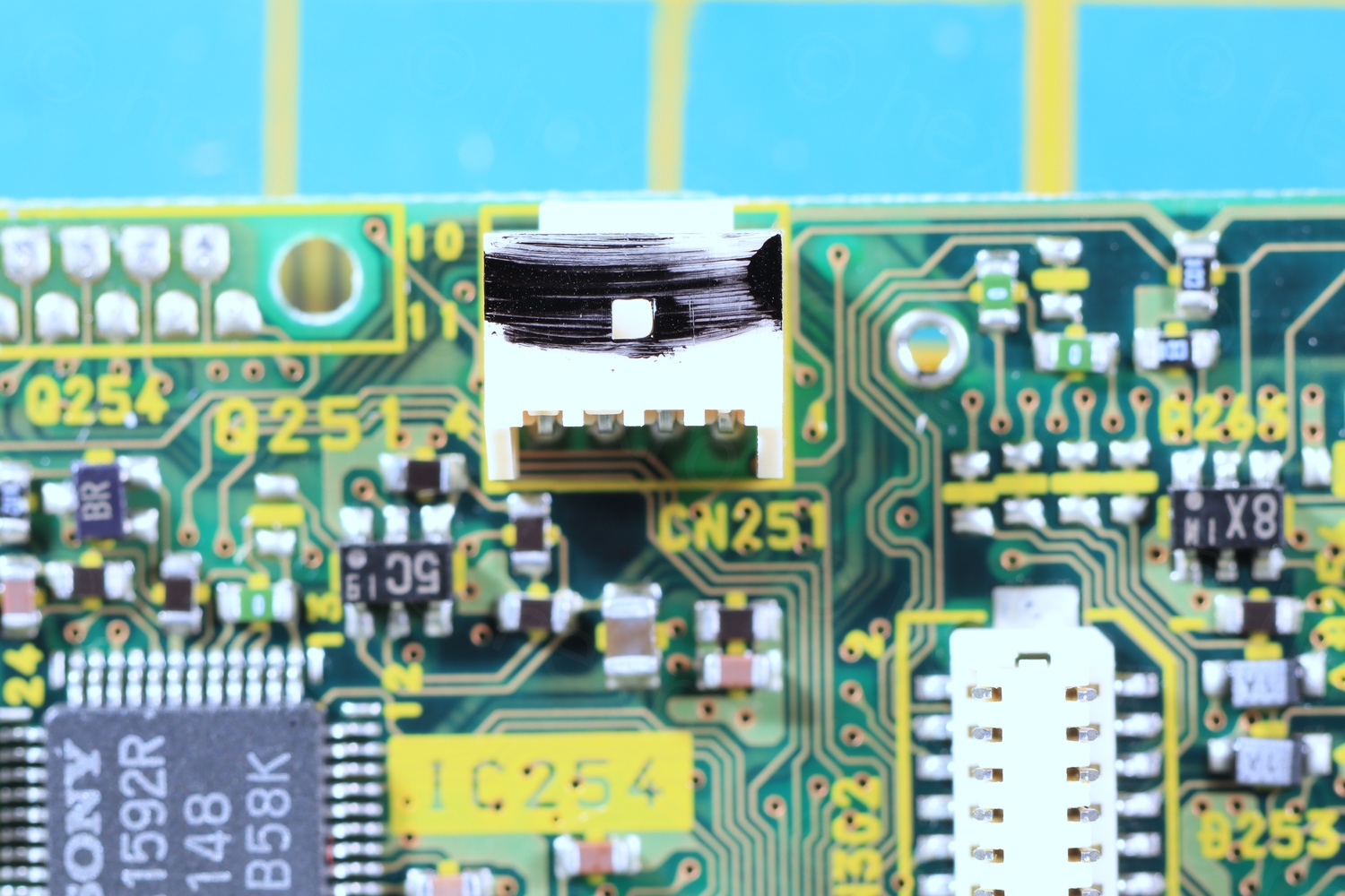
Even if the EVF assembly can be taken apart once the camera plastic body is off, I needed to continue to dismantle the camera to get at least to the plug of the EVF unit. I usually de-solder these plugs as they make it easier to connect the mini clamps that will deliver the signal – without having to cut the original connecting wire.


mini CRT
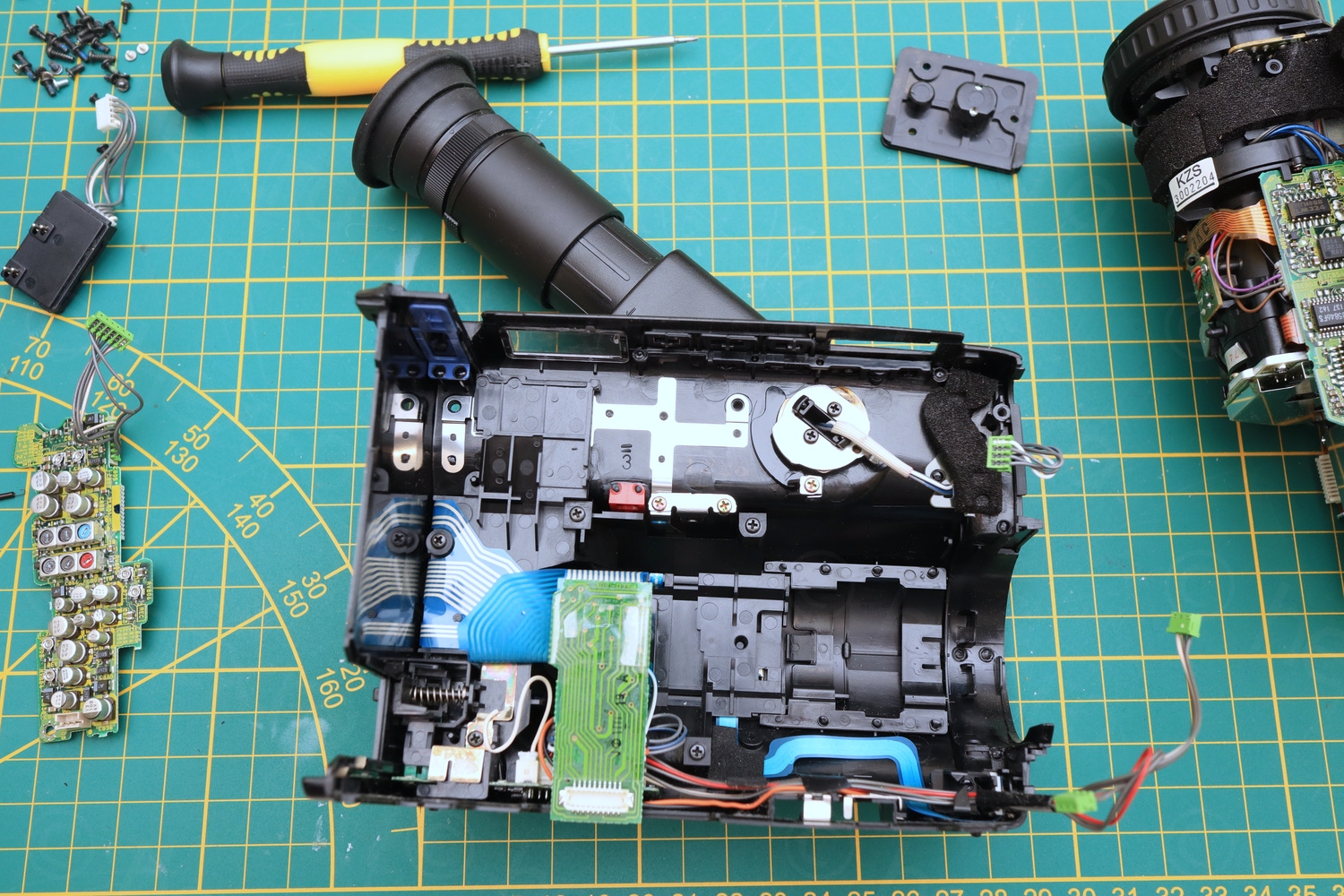
Next step is to finally get the EVF assembly out and have a look inside.
Attached to the side panel 
Screws out 
Screws out 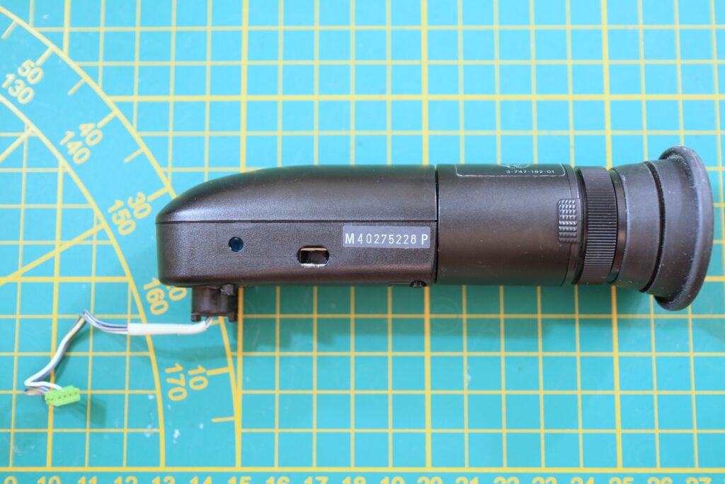
Side view 
Protective plastic 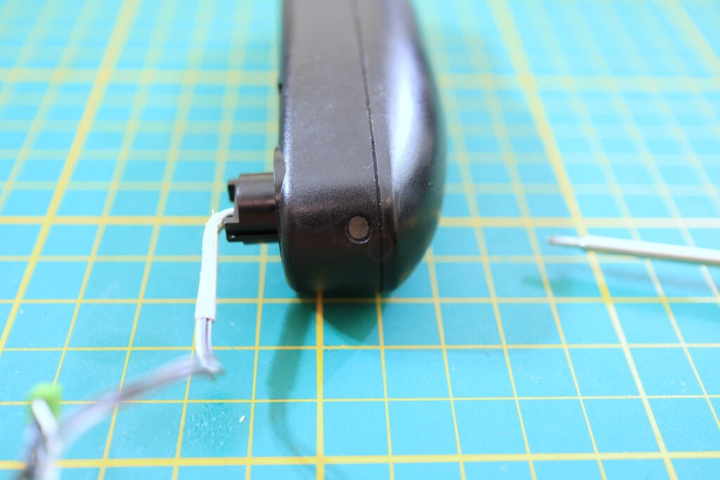
Recording LED 
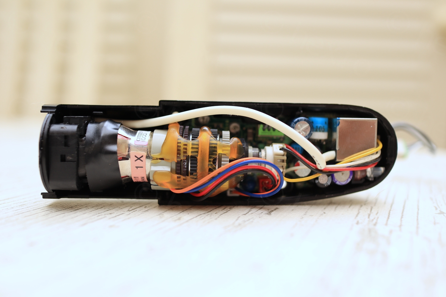
First look inside 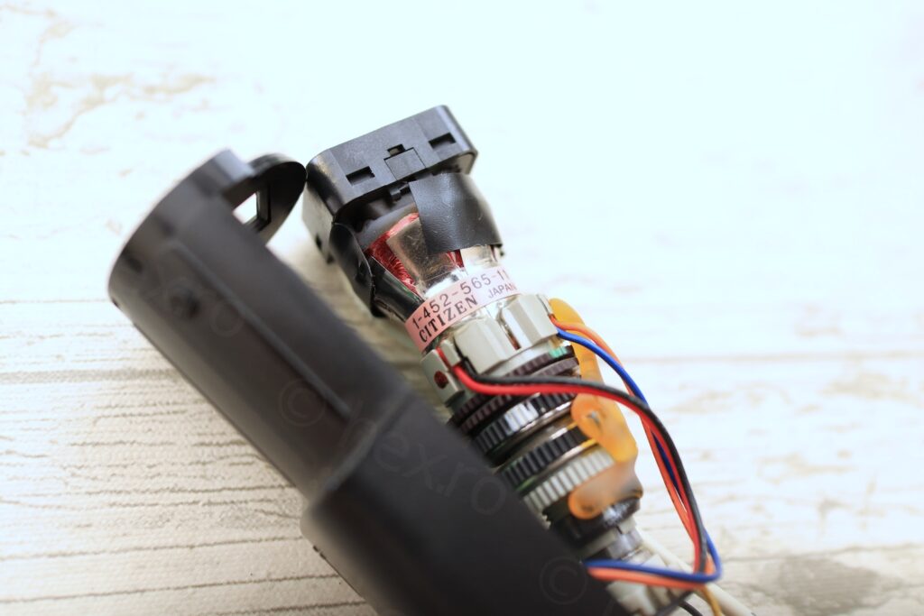
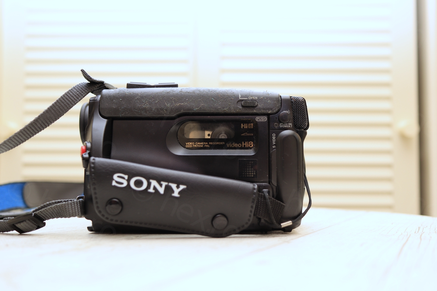
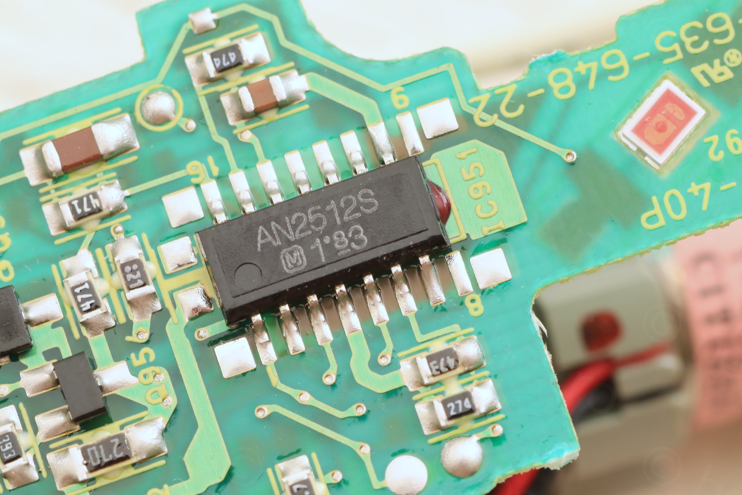
Model Name 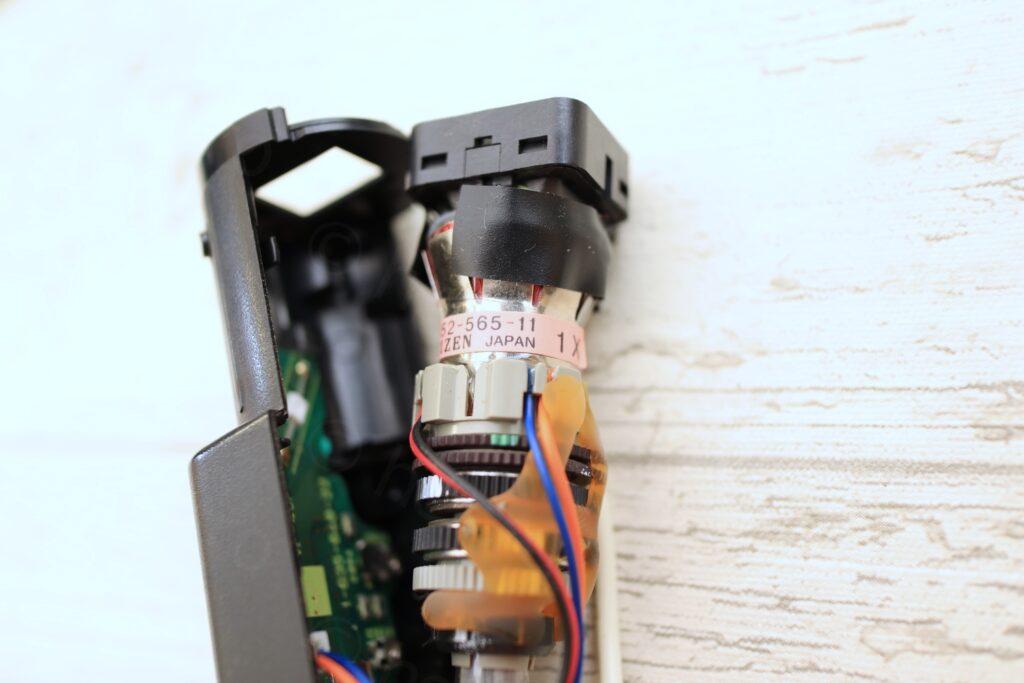
Model Name 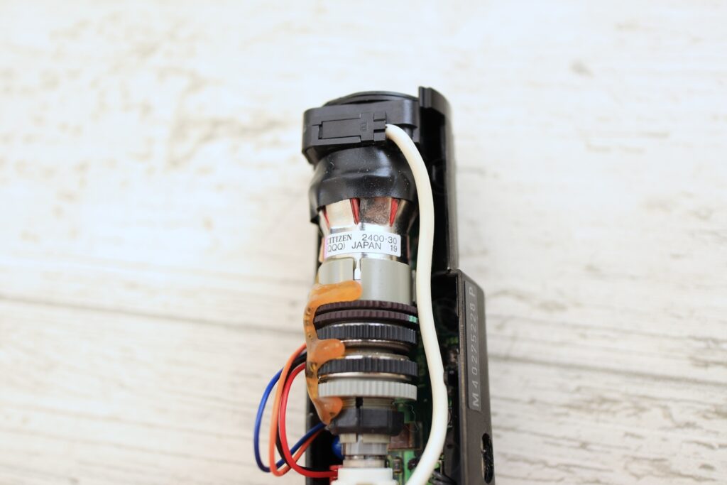
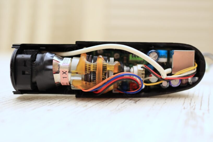
Citizen 2400-30

Identifying the signal cables was not difficult. GND is the second wire just after the White one (first gray wire after the White one) as this is always connected to the case of the Flyback Transformer. VCC is also connected to FBT, and VCC is the White wire (the only FBT pins that are not connected to GND and which have continuity to the plug are the VCC pins). The Video Pin was harder to indentify, as the CRT would not turn on …
I decided to have a look at the back of the driver board. This was a little tricky to take out of its enclosure due to tight fitting and a little plastic tap that was holding it in:
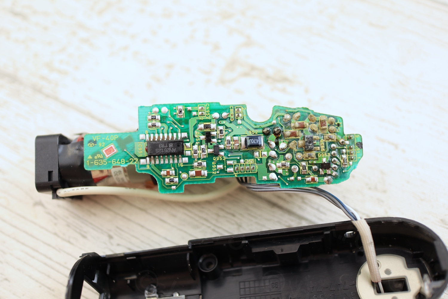
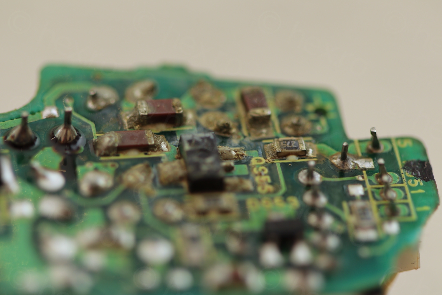
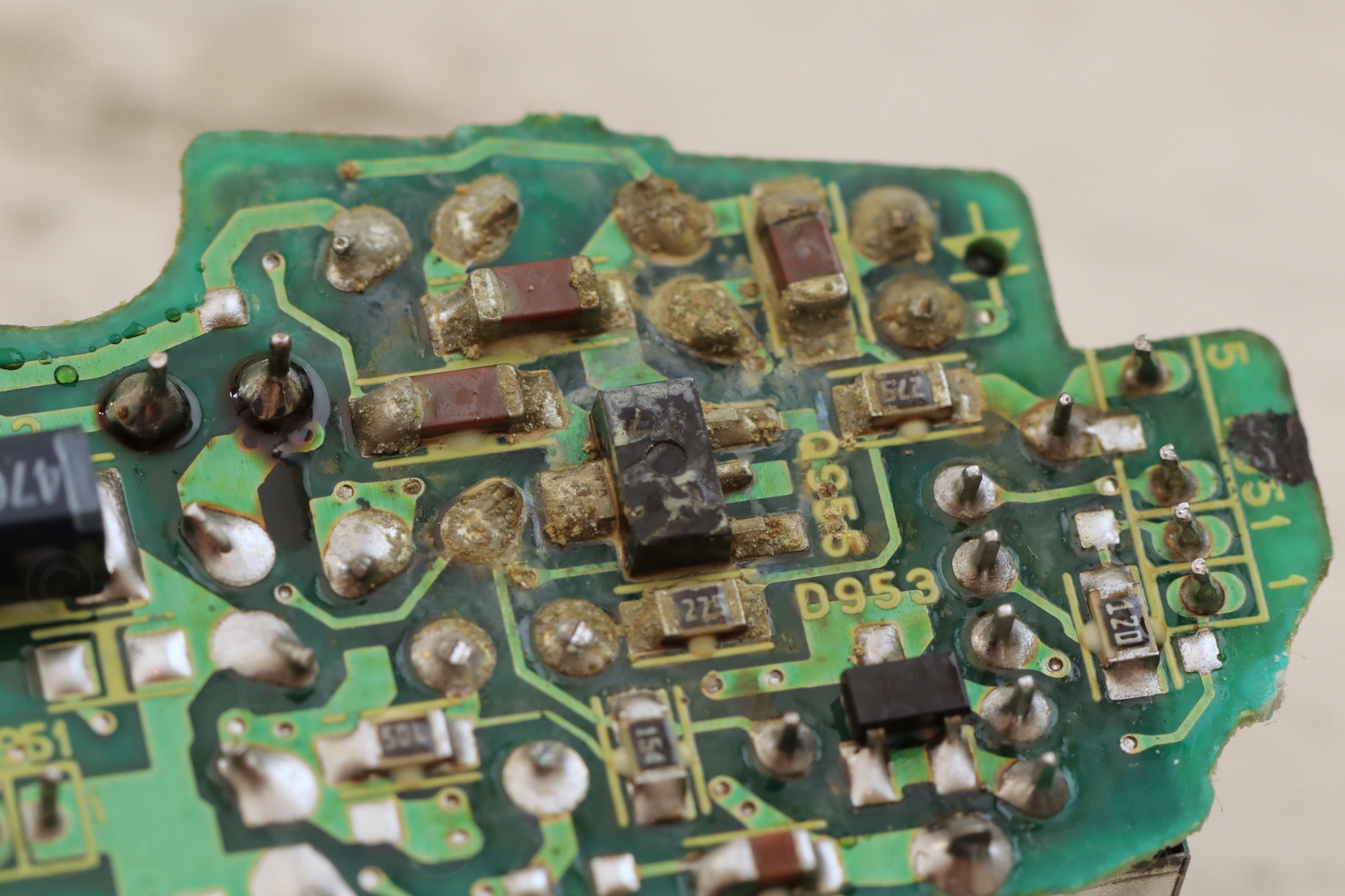
And driver board looked very very messy. Was wondering what it could be. It may be capacitor discharge (as I have another proof below), but on the other hand, this side of the driver board is pointing exactly towards the pass-through hole where the wire goes to the camera body. So it may have been just water going in and corroding things.
I tried to clean with Isopropyl alcohol – and although it looks better, the solder connections lost their shine.
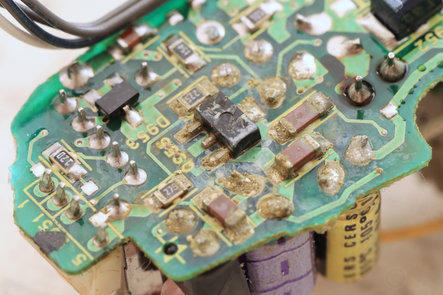
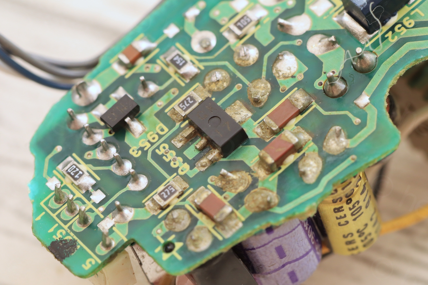
There was still no life from the CRT.
Driver board debugging
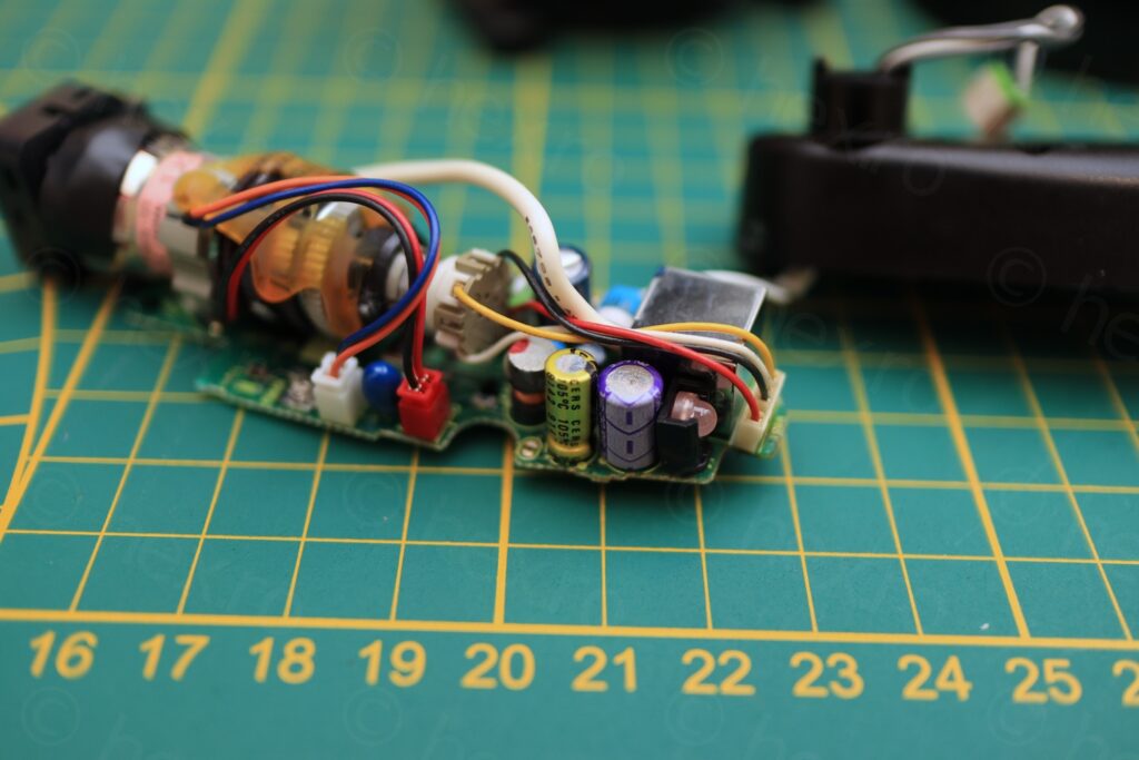
Uncertain of the source of the corrosion on the driver board, I decided to do an in-circuit ESR measurement of the 3 electrolytic capacitors using Peak Atlas ESR70 Plus meter:
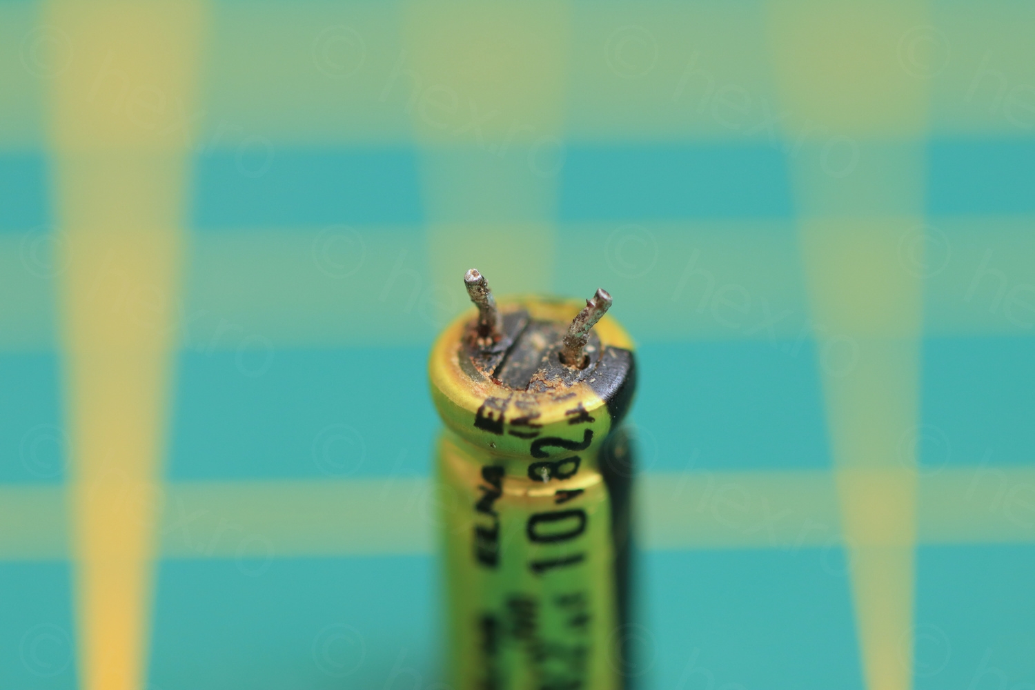
This showed that an yellow cap, ELNA 82µF@10V had a very high ESR. The other two reported good ESR, but their capacitance was too high. I decided to de-solder all three and measure them outside the circuit:
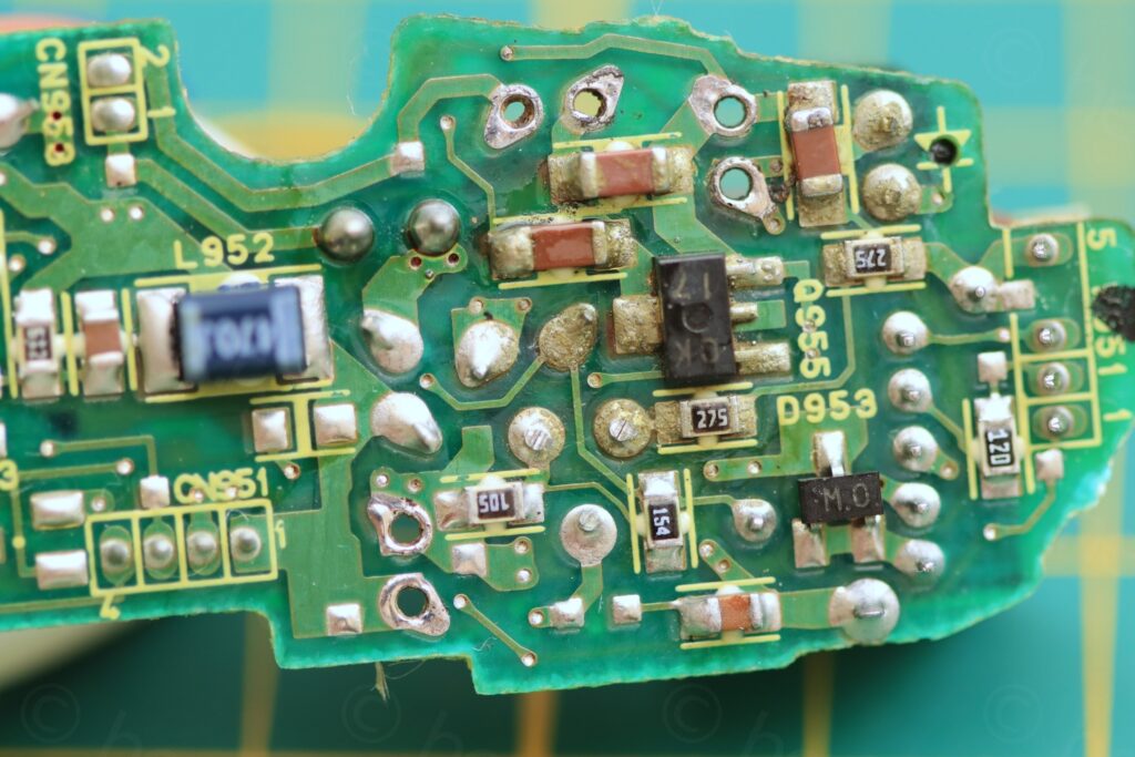
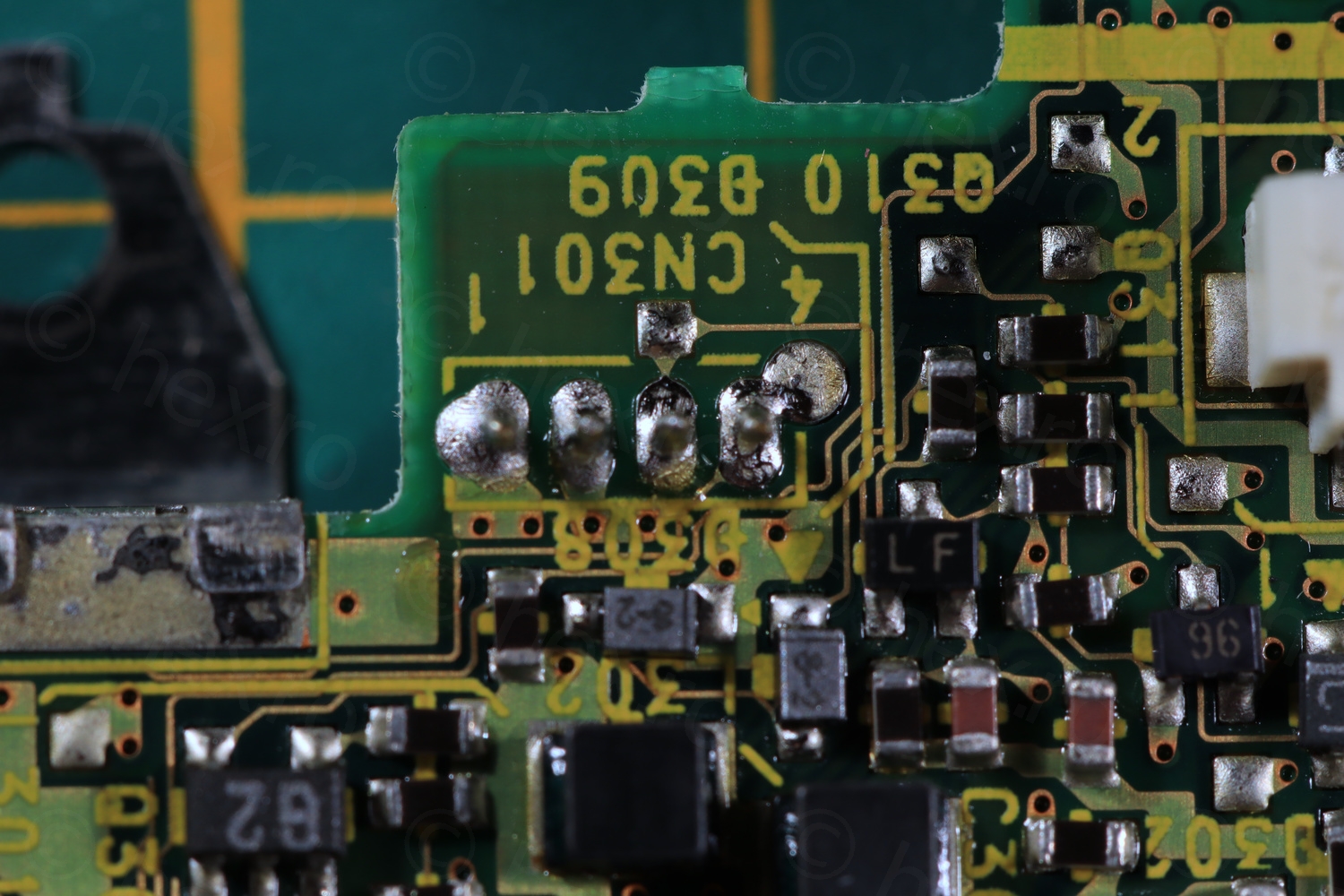
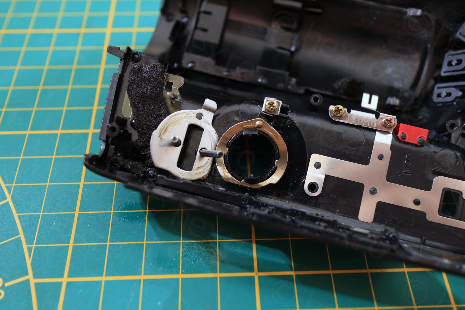
Clean pads 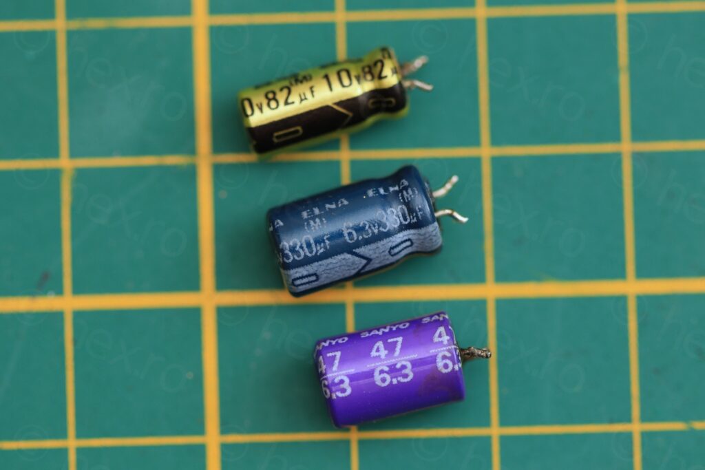
Capacitors 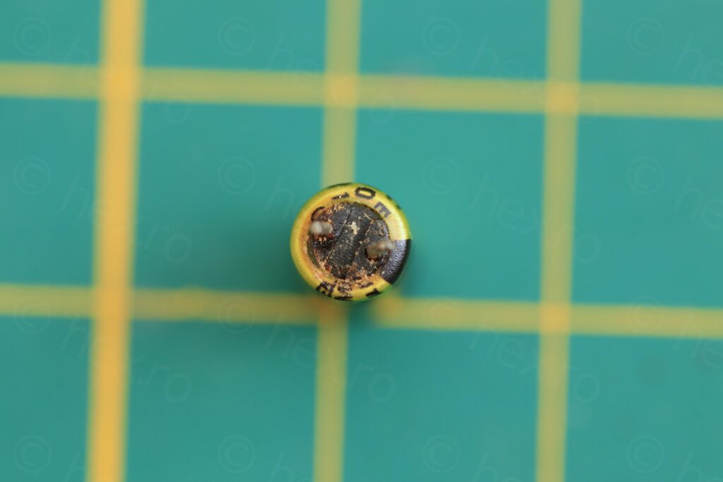
Top view 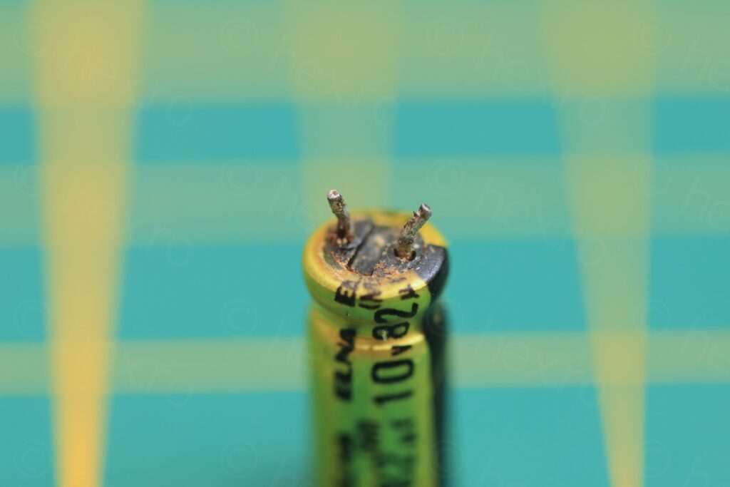


I have measured the capacitors and the Sanyo 47µF @ 6.3V was measuring 53µF with ESR 0.05Ω, the Elna 330µF @ 6.3V was measuring 268µF / ESR 0.37Ω but the yellow Elna 82µF was reported as “Open circuit/low capacitance”.
I would have liked to swap them all, but I worked on this on a Thursday evening, and if I would order the parts on Friday, Farnell probably would not have time to ship the same day; more realistically, they would have shipped it Monday and I would get them Tuesday, 5 days after. What to do ?
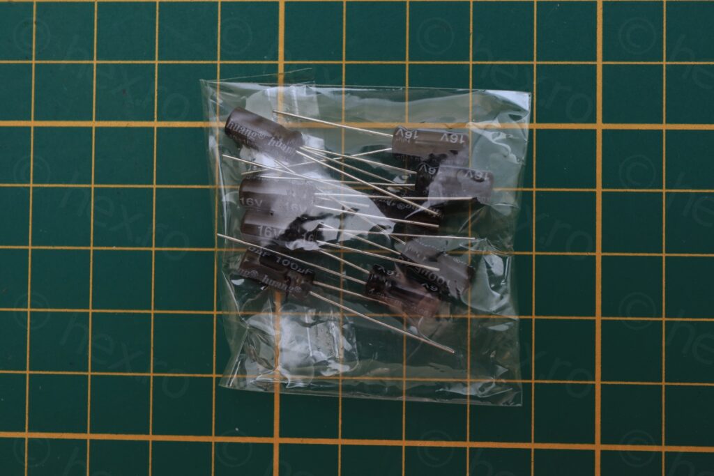
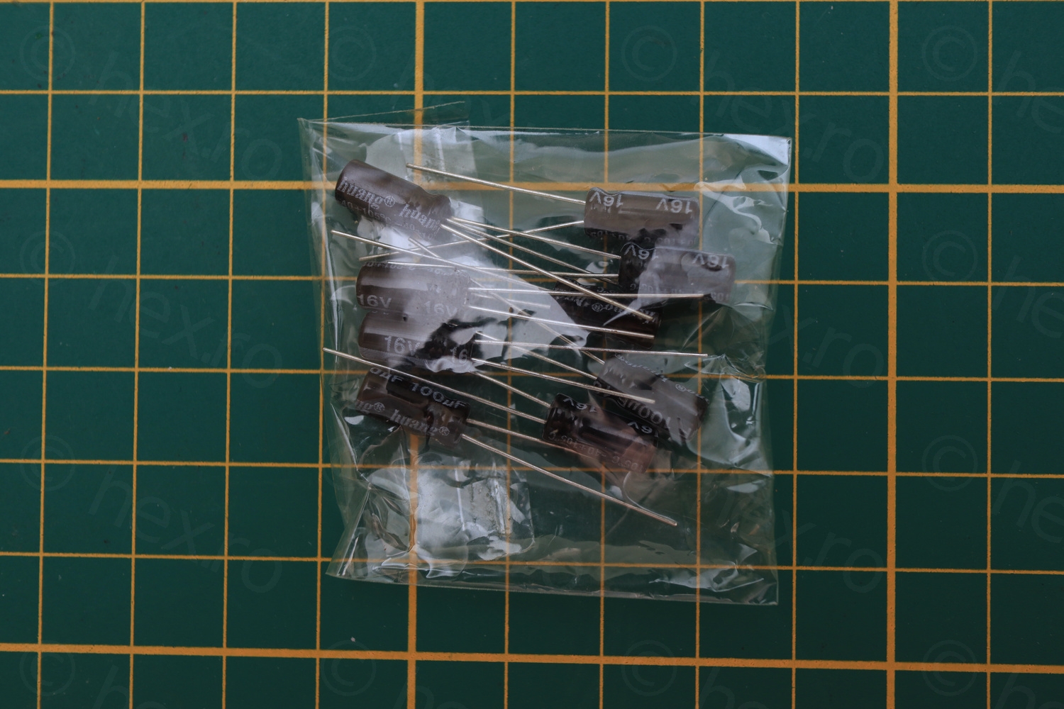
I remembered I have some no-name capacitors that I kept thinking who knows when I may need something urgently ? Sometimes Aliexpress orders come with a small bag of few capacitors as a present. And as luck would have it, I found a small bag of 100µF@16V capacitors:
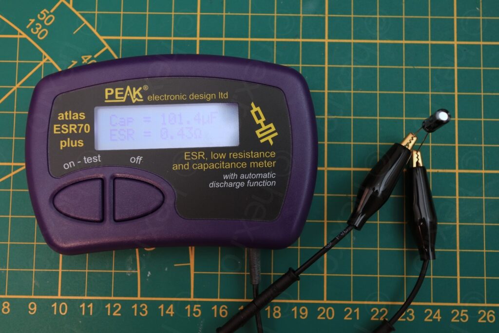
Capacity 101µF / ESR 0.43Ω

The decision was easy. The Sanyo 268µF capacitor is almost at the -20% limit (vs the stated 330µF), and the replacement cap is almost at the +20% limit (vs the required 82µF) thus, the working capacitors went back to the board, and the new one was installed:
Before 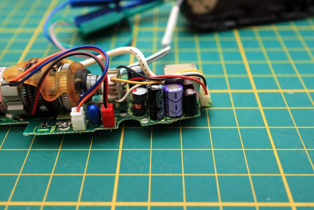
After
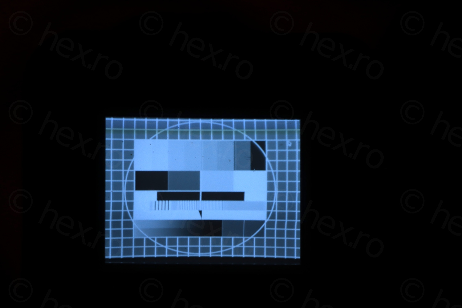
And surprise surprise, the CRT came back alive 🙂

With trial and error, the Video IN signal is the third one after VCC (after the white one) and the last gray cable on the connector turns on two red LEDs (it is active low).
I found a very well scanned and complete service manual for Sony CCD-TR705E here. Amazing stuff. The manual is very detailed when it comes to the EVF unit, and it also presents the waveforms that are to be expected at specific points on the driver board.
My curiosity got the best of me and decided to try to scope the driver board, as I am not experienced with these CRTs, and I was too young when these were still the rage. By the time I learned electronics, everything was already micro controllers.
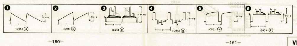
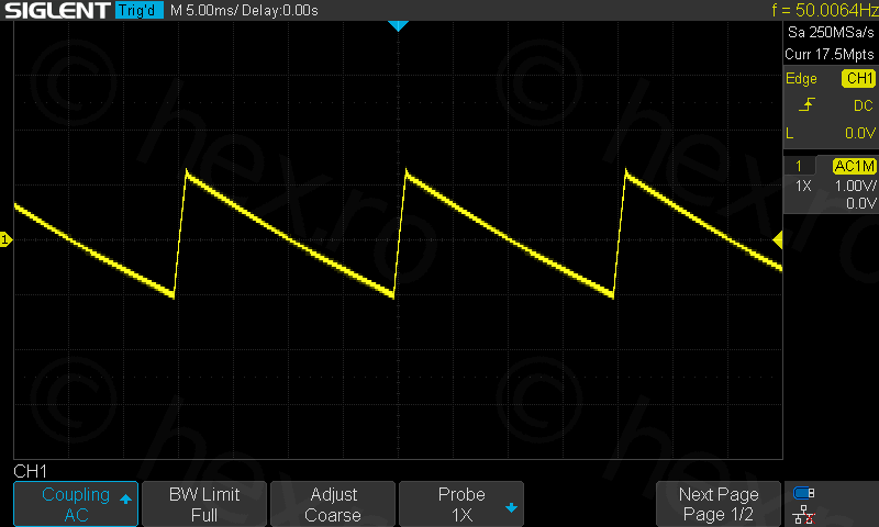
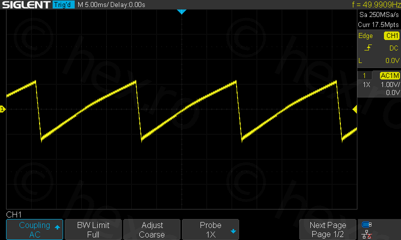
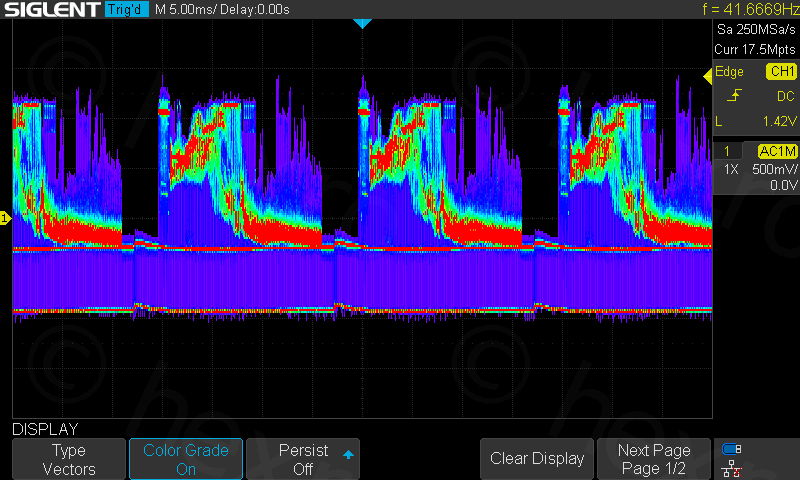
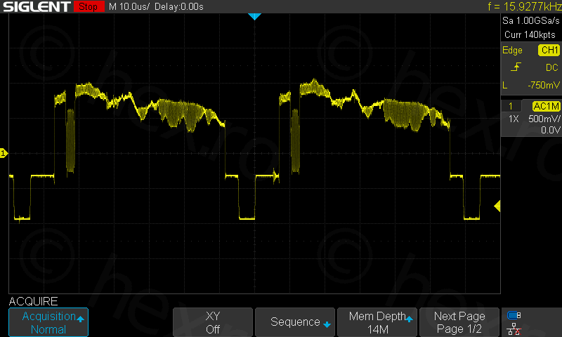
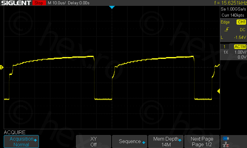
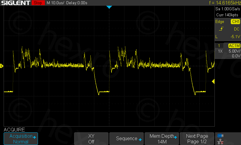
Perfect match at all the points! I hope I won’t need to debug other driver boards / old equipment by having to look at the waveforms, but at least now I know a bit how they should look like.
I like to try these EVF units with Manic Miner. I can both play an old game that I like and also, I can see how the CRT behaves. Recorded with Canon 100mm Macro 1:1, at very close of the minimum focusing distance. The video goes a bit outside the CRT viewable area, but it is very sharp and no ghosting:
A look at it before putting the EVF unit back together.

This was an interesting camera to work with, I have two more identical ones which I will open at one moment. Not sure if I will post them, unless something else is different than this one.
Marcantoine
Sometimes it is a good idea to look for pictures of a certain device on Google. Text search dit not reveal anything useful. Just wanted to get that viewfinder of the CCD-TR705 to live again – out of curiousity.
4 wires, about 5V was obvious, but where….
Thank you very much. Another (useless) tiny CRT came back to live. Fascinating stuff. 🙂
I will keep that little thing, just to light it up sometimes and feed it some Signal 🙂