


Introduction
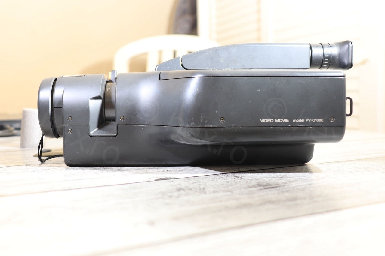
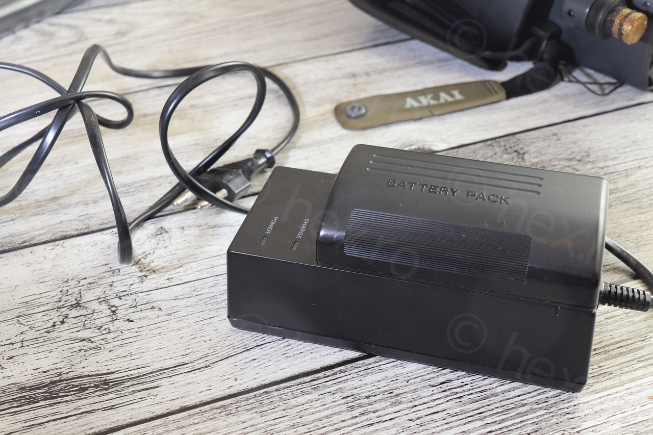
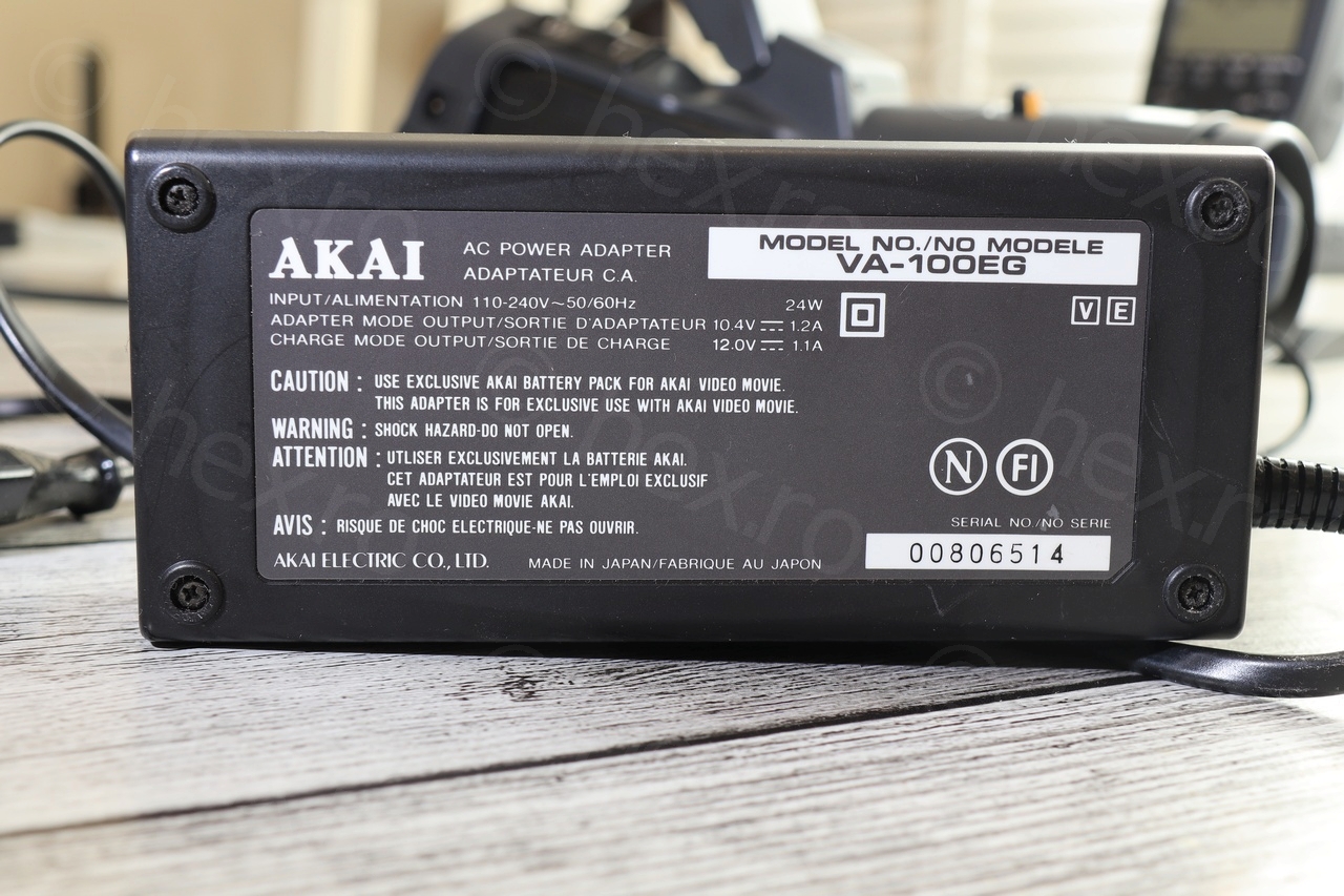
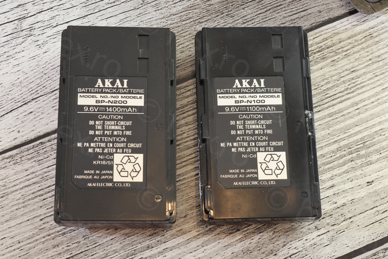
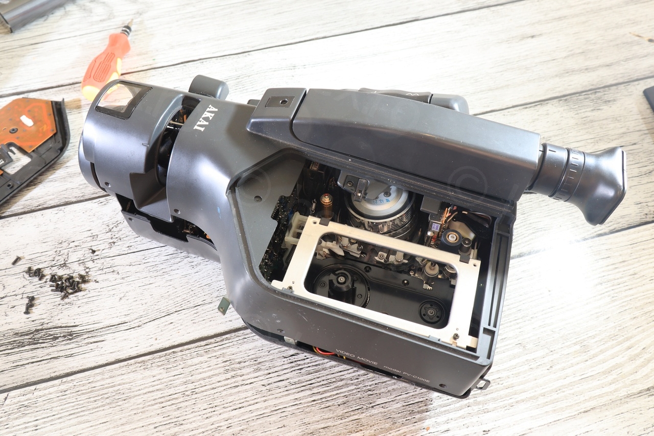
I found the Akai PV-C100E Video Camera at a flea market and figured it it may use a mini CRT as a viewfinder. The seller insisted to sell it with the charger and the batteries – so, I took it.
Opening Up
The camera was easy to open up (accessible Philips screws) but it took a bit of time to fiddle with the Electronic View Finder to detach it from the main plastic body. Circuit was clean, although, I find the camera shape funny, is like bread held on its side 🙂
Galleries


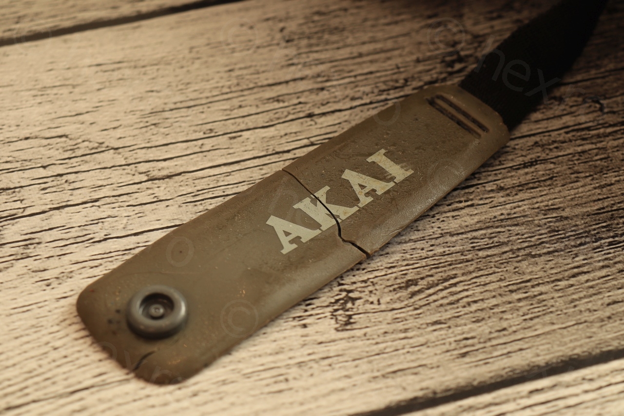
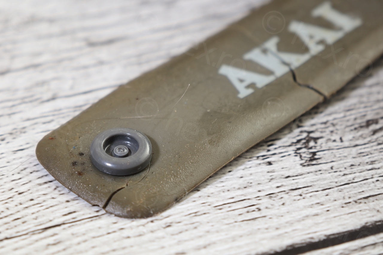
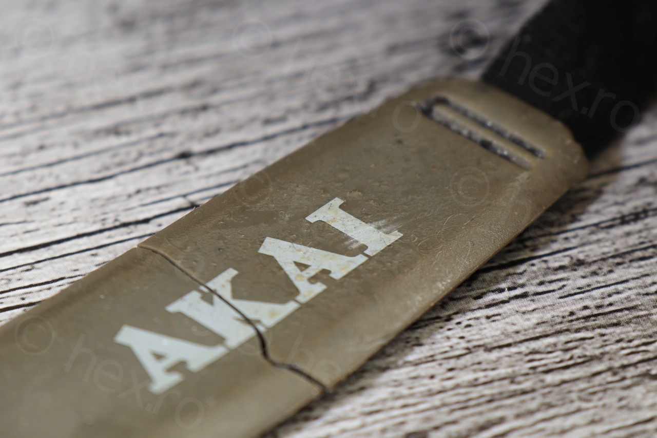
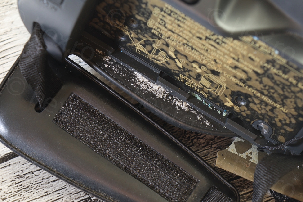
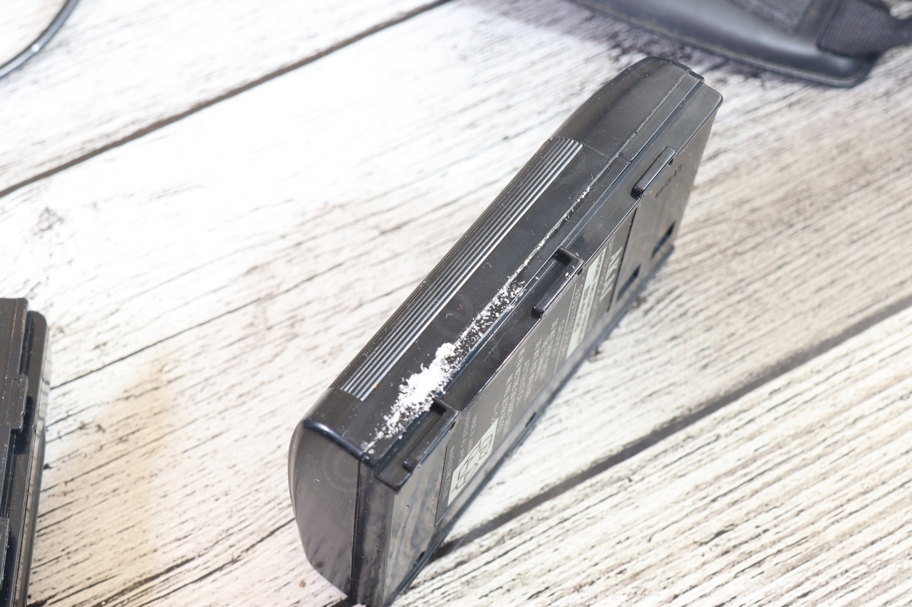
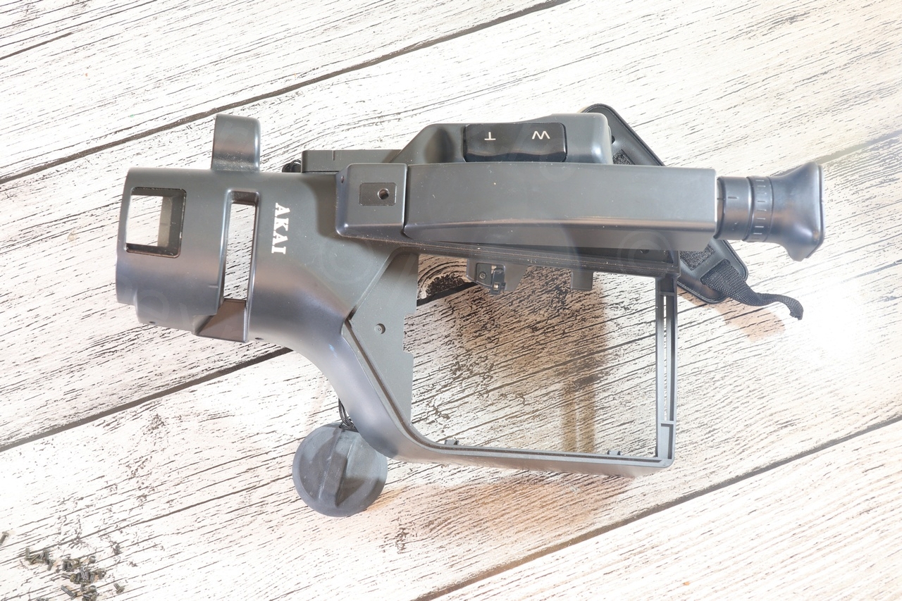
The camera handle (with AKAI text) was very sticky and provided batteries are corroded. These camera dismantling hobby requires lots of trips to the Recypark.
Dismantling the camera itself wasn’t difficult at all:

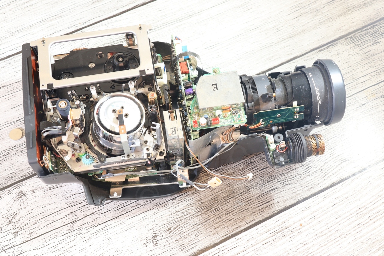
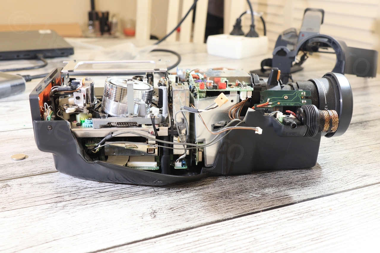
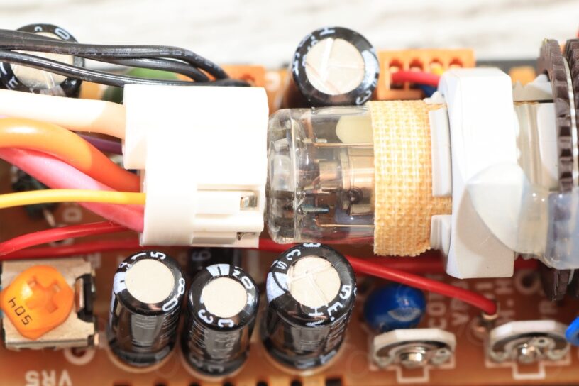
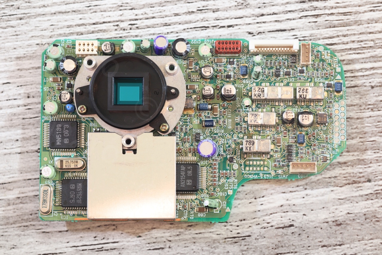
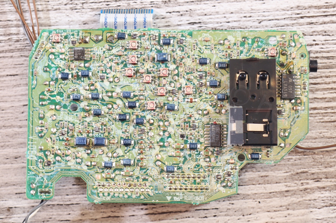
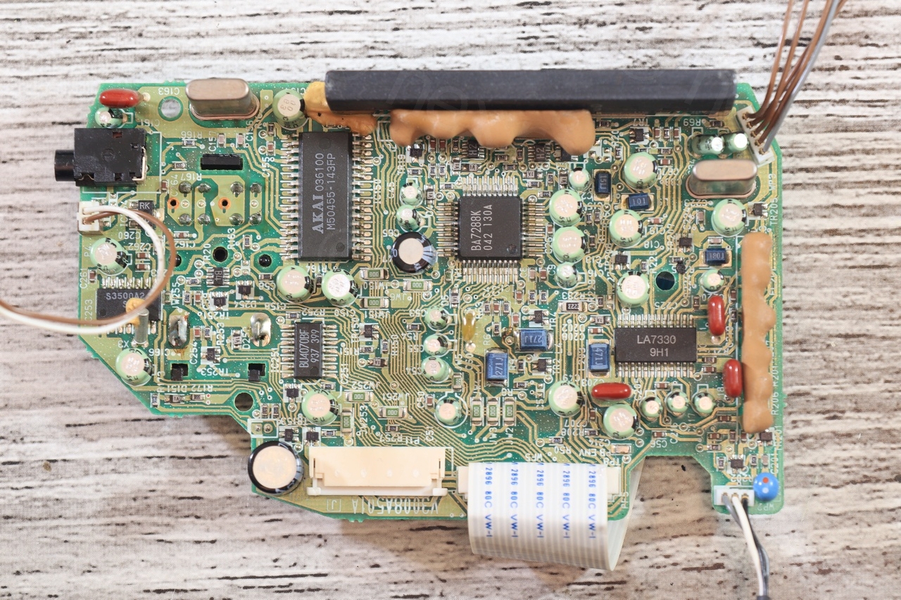
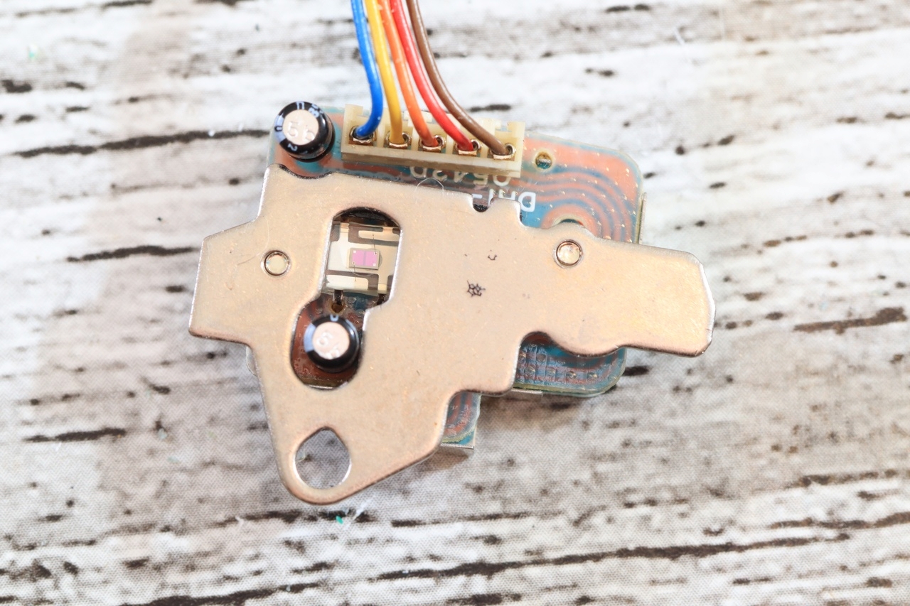
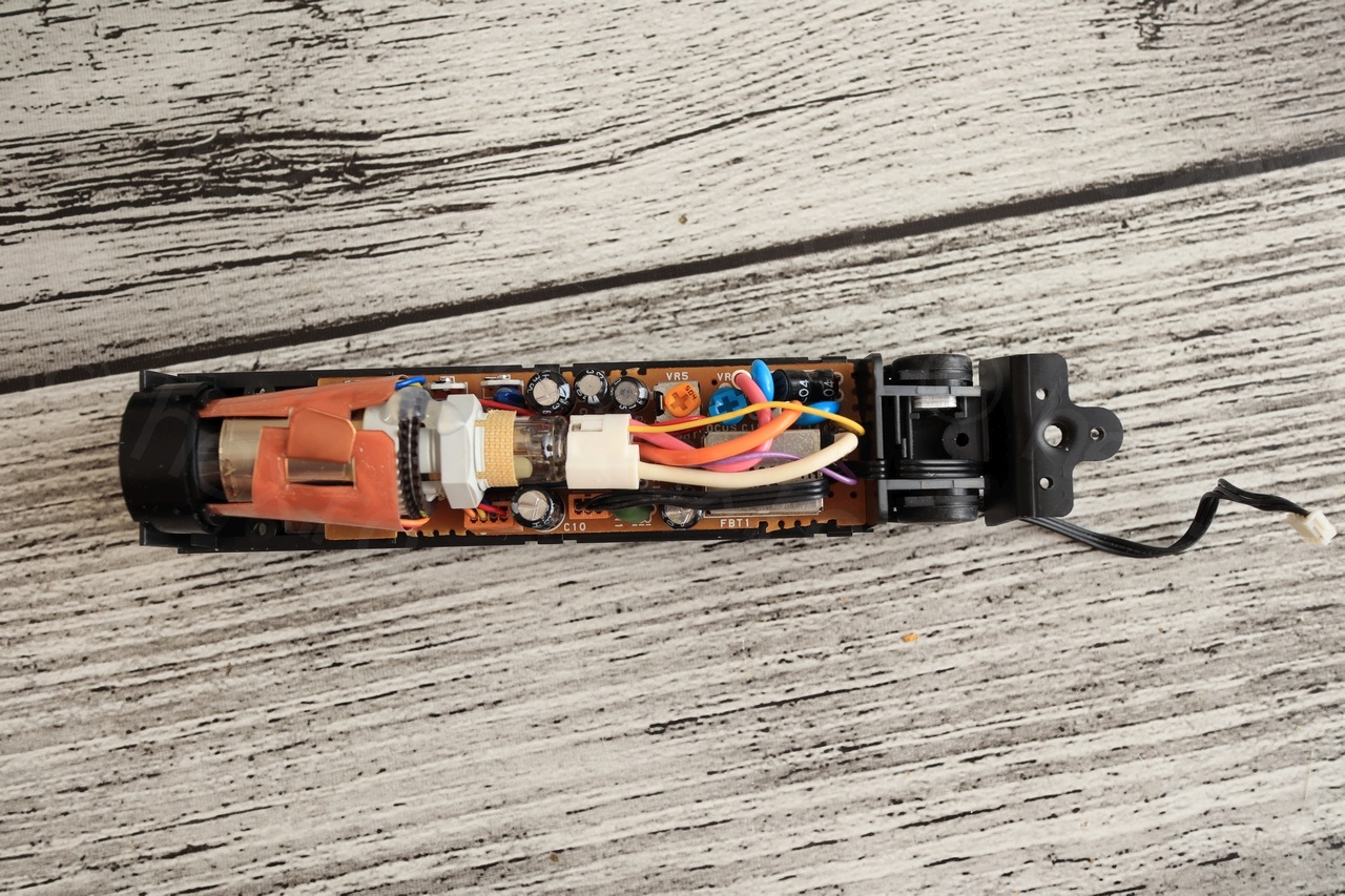
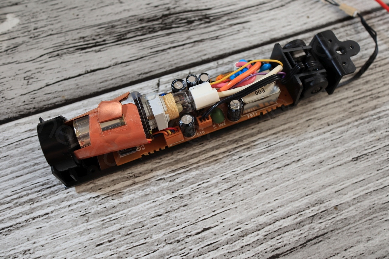
The boards are neat and proper, very impressed with the density of the components. The main optics also move some additional small lenses that focus the light on an additional sensor which is pictured last:

An interesting discovery was the diaphragm shutter mechanism that I was able to take apart from the lens assembly, it seems very simple and efficient:
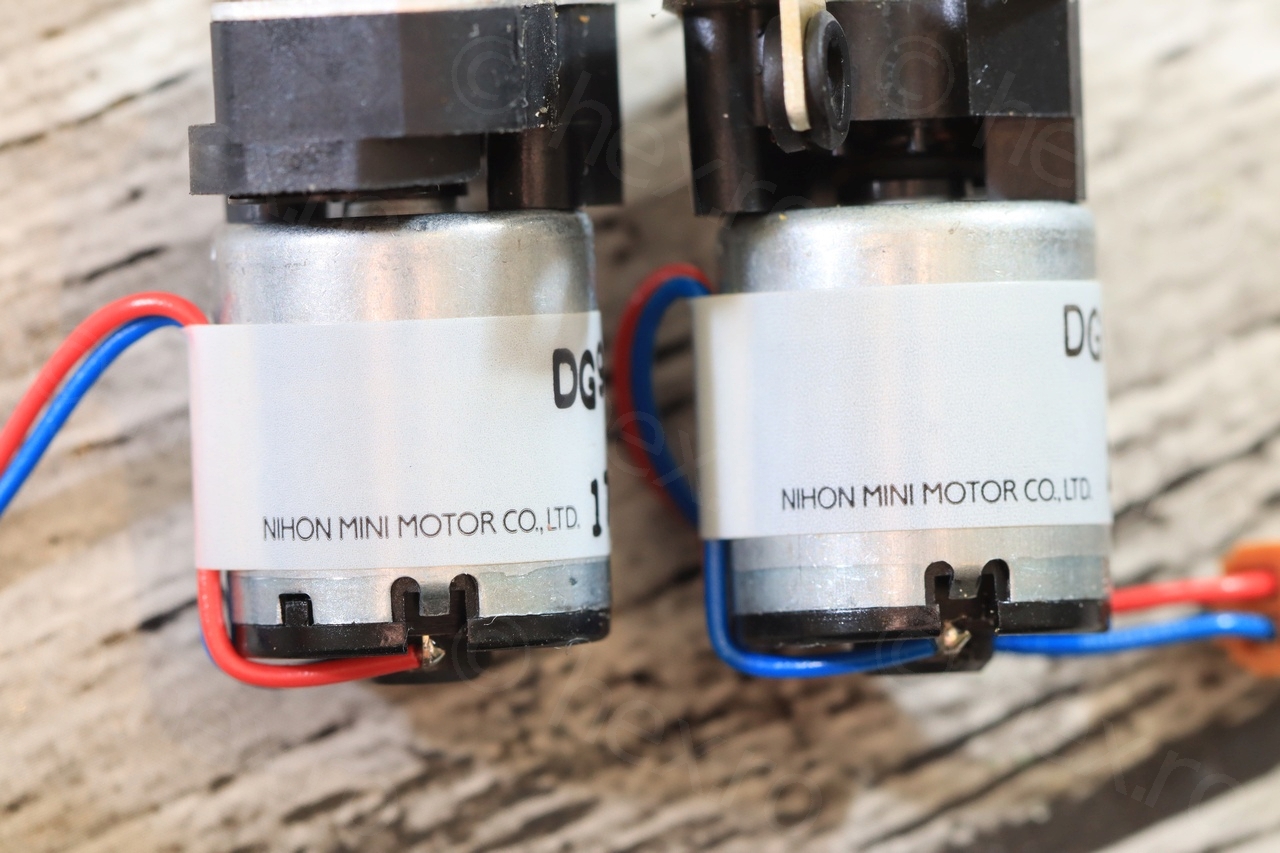
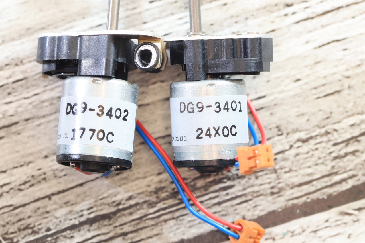
I have decided to keep few parts: the quartz, two motors as well as a 0.018F capacitor which I have not tested yet. The motors are Nihon Mini Motors DG9-3401 and DG9-3402. Decided to desolder some connectors so that I don’t have to cut the cable that comes out of the Electronic View Finder.


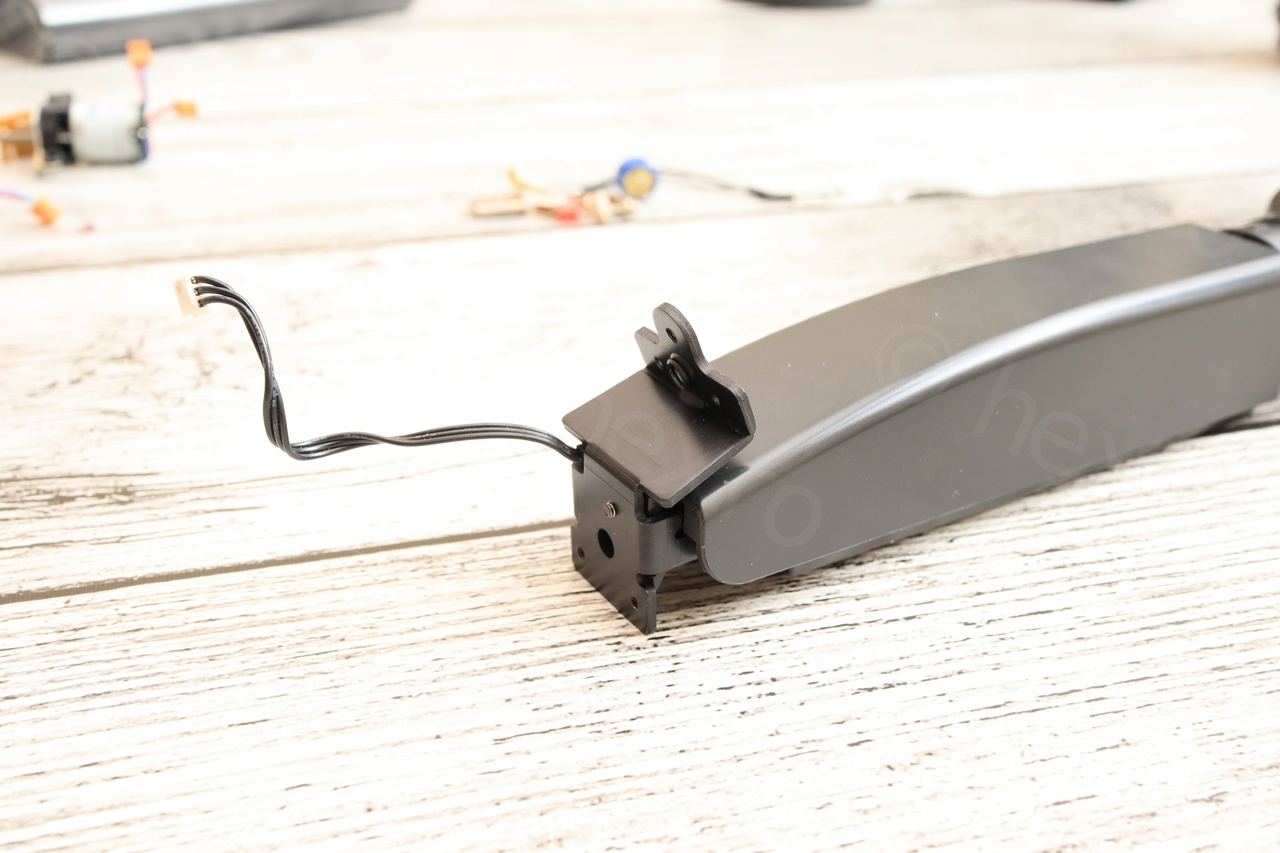
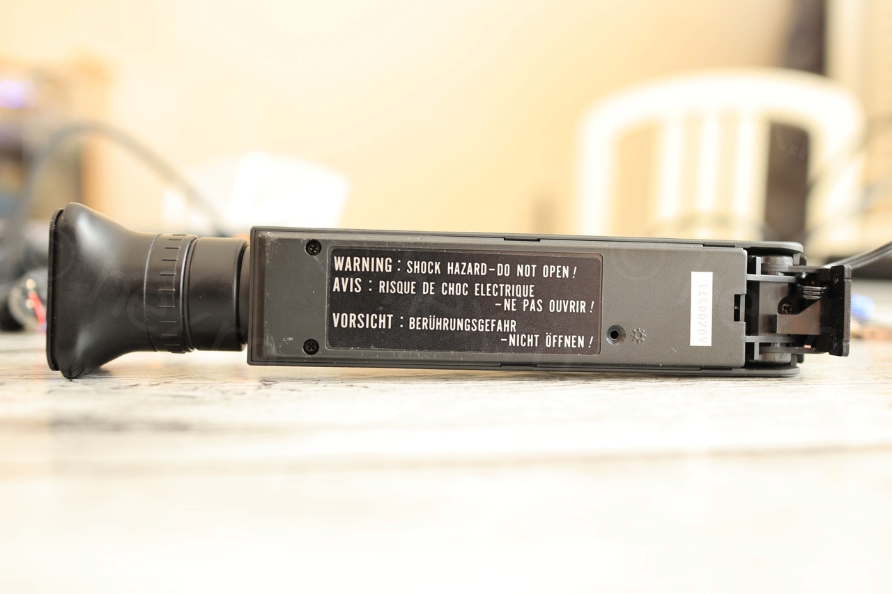
Electronic View Finder
I usually handle the EVF separately as I need to remove the rest of the camera from the photoshoot area. I had already spotted that the signal cables to EVF will pose a challenge to ve identified as they were not color coded. On the other hand, there are only 3 cables, so that’s good.
First some general overview:
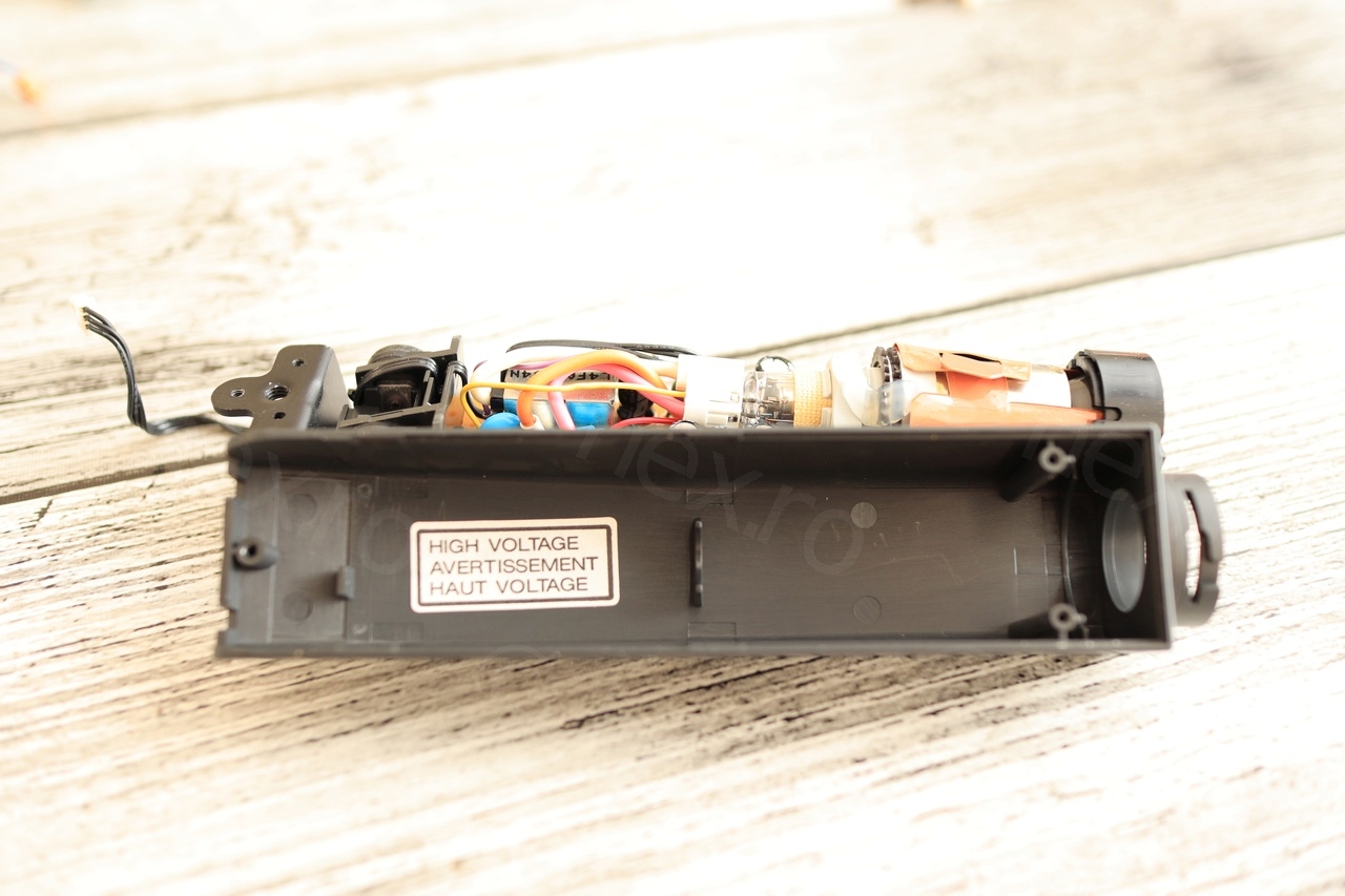


First we can see that the brain of the board is AN2512S chip (which I found in a different board on a different camera). Produced by Panasonic.
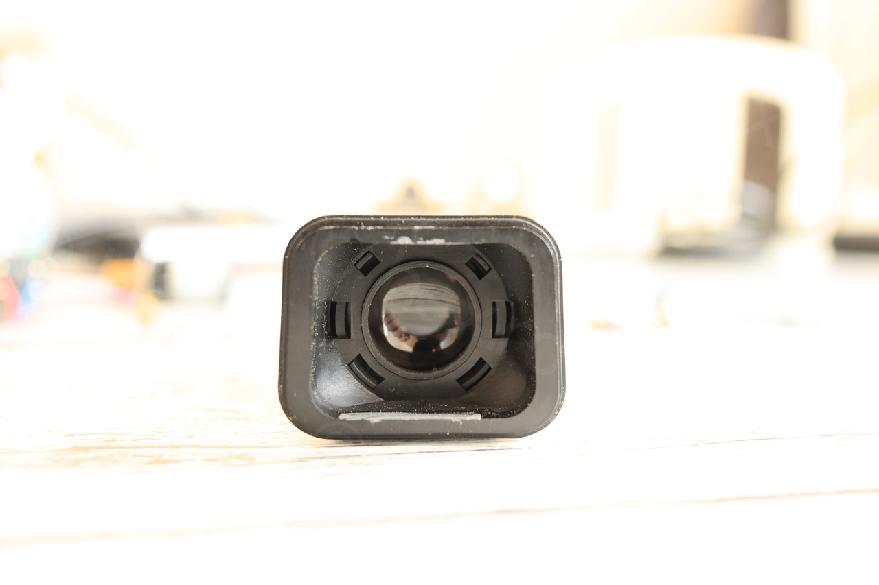
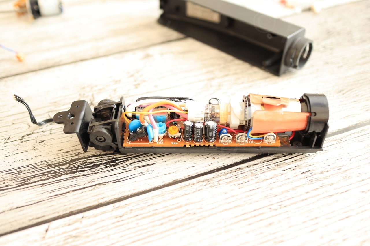
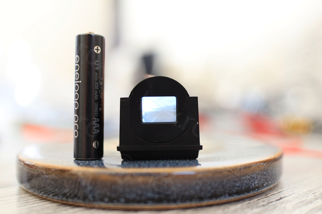
The rectangle opening to the CRT has a common dimension I see in most mini CRTs, about 11mm x 8mm. I’ve tried to measure it more precisely, but I was too afraid not to scratch the front protection with the metallic calipers. The closest I could pickup was 11.11mm x 8.4mm.
Determining the Ground Pin
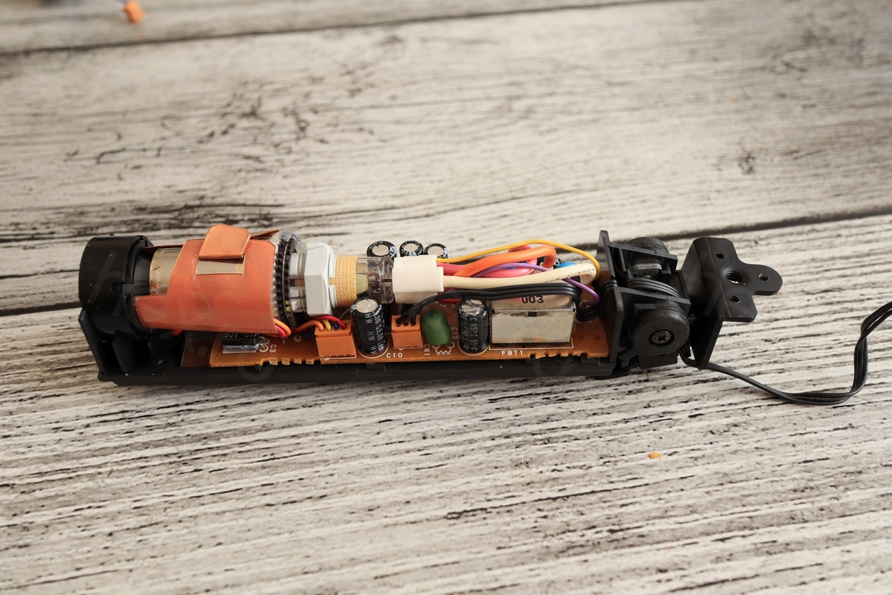
On these boards, it is easy to pick up the GND on the case of the Fly Back Transformer, which, besides the CRT itself, is one of the biggest components on the board:
Once the ground pin identified, I tried to measure the resistance between itself and the other two pins, as a lazy way of identifying the possible connections. It turned out that Video IN pin reports almost open connection (>4MΩ) while the Vcc pin has much smaller resistance which is also varying as you measure – probably indicating a Capacitor on the way.
Thus, looking at the connector, one exterior pin is GND, the other exterior pin is VCC and the middle pin is Video In.
Determining VCC
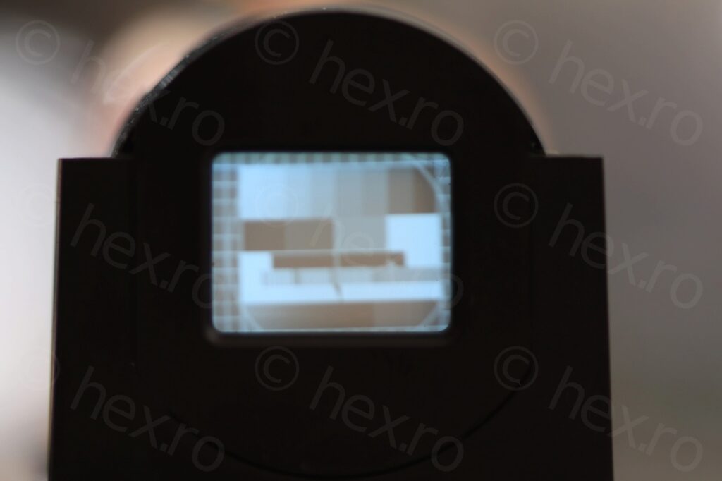
Unlike other EVFs this specific one had no markings indicating the possible VCC that it may expect. Decided to power it at 7.5V from the wall-wart and it worked! However, the image was very blurry and too magnified. If other mini CRTs are able to fit the standard calibration circle, this one was showing it zoomed in and cut. Parts of the circle were outside the viewable area as you can observe:
I switched the wall-wart to 9V and the image became even more distorted, thus, I decided to take out the bigger power supply and trying out. I had set the power supply to 8V sharp and limited it to 0.5A and proceeded to fiddle with the Fine Tune control. This was an epiphany! As I was lowering the Voltage, the image was reducing in size and becoming sharper. I was able to narrow the input voltage to around 5.3V. 0.2V either way has a dramatic impact on the sharpness of the image.
On the left a video recording with Canon M50 + Canon 100mm Macro (closest focusing distance) also magnified 2x. On the right, a video of the Power Supply, as I fine tune the voltage. I’ve synchronized them by the sound of the phone starting the recording. Please observe the correlation between the input voltage and the image sharpness.
I was so happy I found a way to tune the focus as so far it was rather disappointing that mini CRTs sharpness was so poor. One of the cameras I have (that I discovered working) seemed to show a very crisp image while the cassette inside was playing, thus, was I doing something wrong when testing the CRTs ? I somehow thought they have a voltage regulator on the board itself, but it seems not and they are indeed very sensitive to input voltage.
Of course, I had to give it a go at recording a new session of Manic Miner!
All in all, I am happy with this specific camera. It helped me realize some of the mistakes I was doing and then very impressed with the image quality of the CRT, I can’t believe it can be so sharp while so tiny!
Leave a Reply