


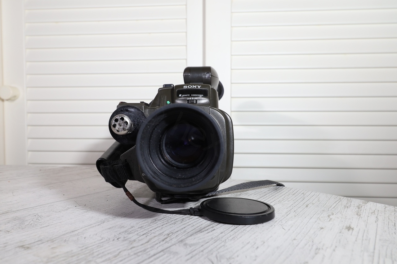
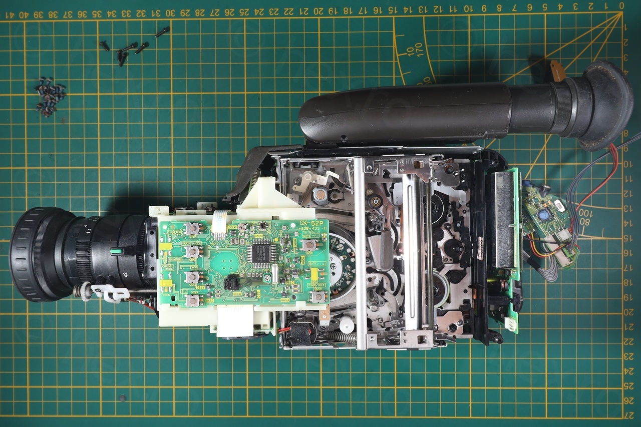
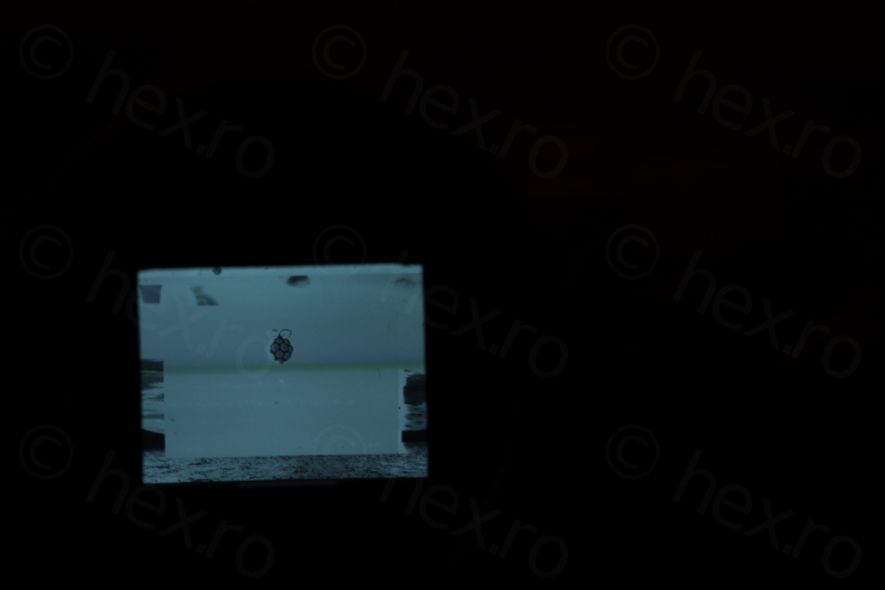
Found this mini CRT inside a Sony CCD-F355E camera I bought at a flea market.
Camera
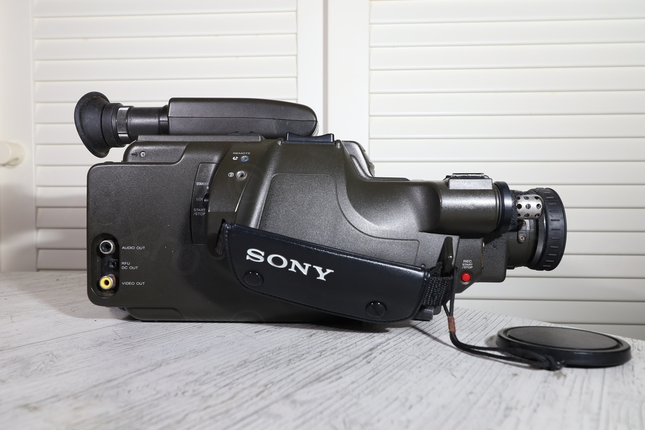
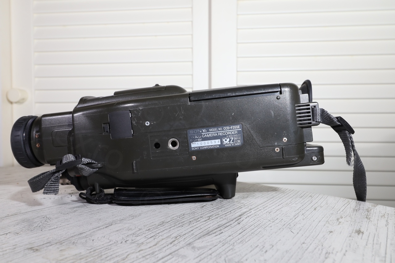
Sony camera looked clean and I was hoping CRT will work without too much hassle.
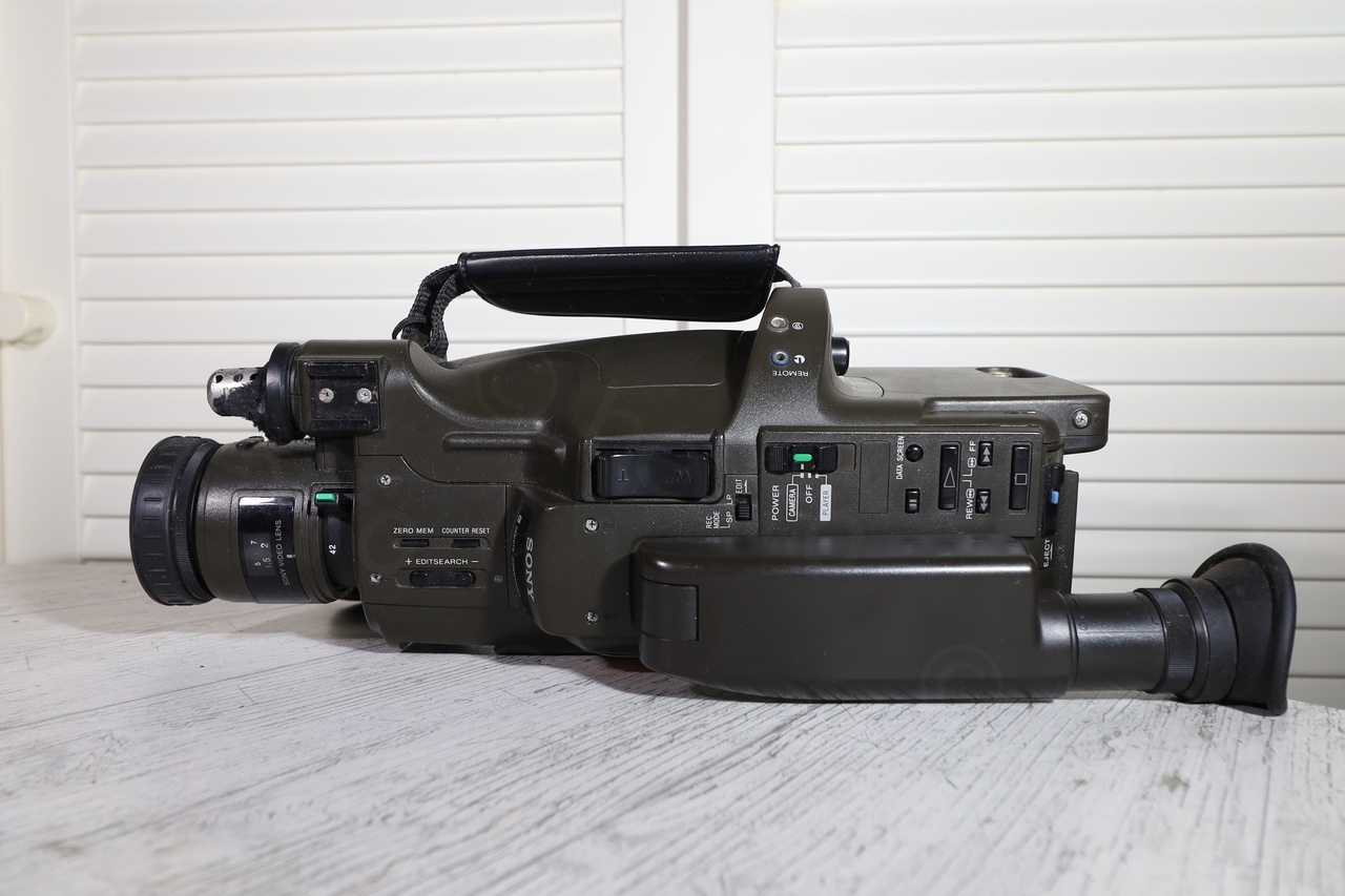
Camera looked good and no signs of corrosion:

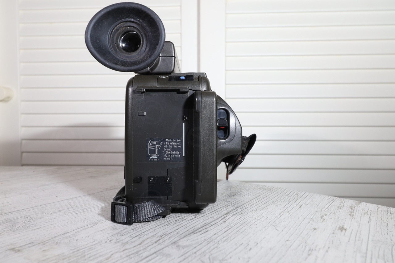
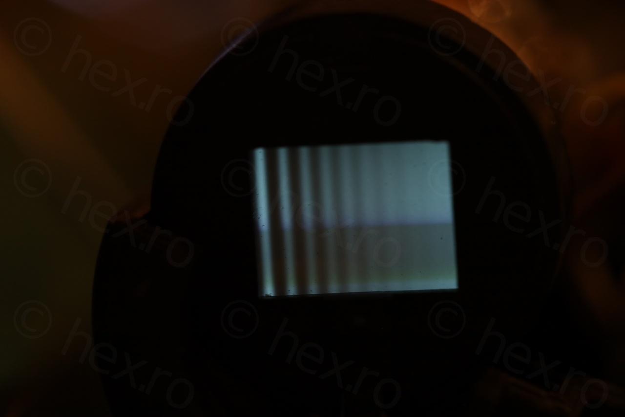
I decided to power it up (there is a button that the battery keeps pressed, which is queried upon startup. If the button is not pressed, camera shuts down). However, things were not looking good, image was not stable and had a bunch of alternating dark and white bands:
I did encounter other cameras that had bad capacitors and had weird issues – I proceeded to take it apart knowing that this will not be an easy win.
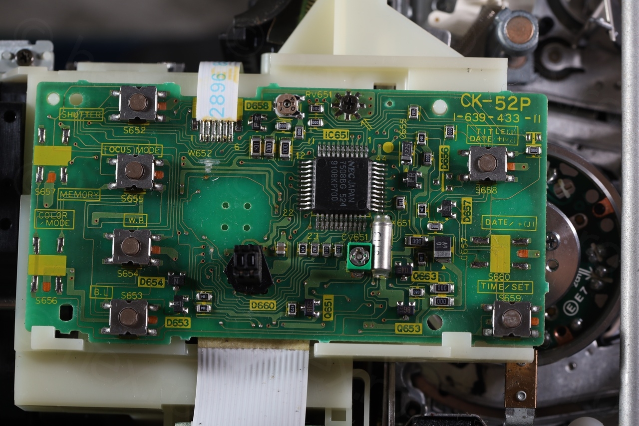
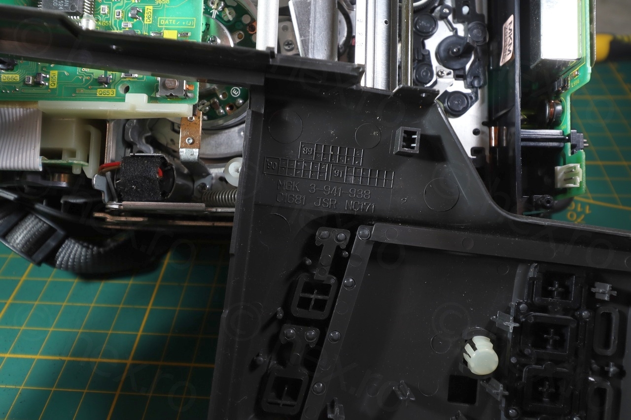
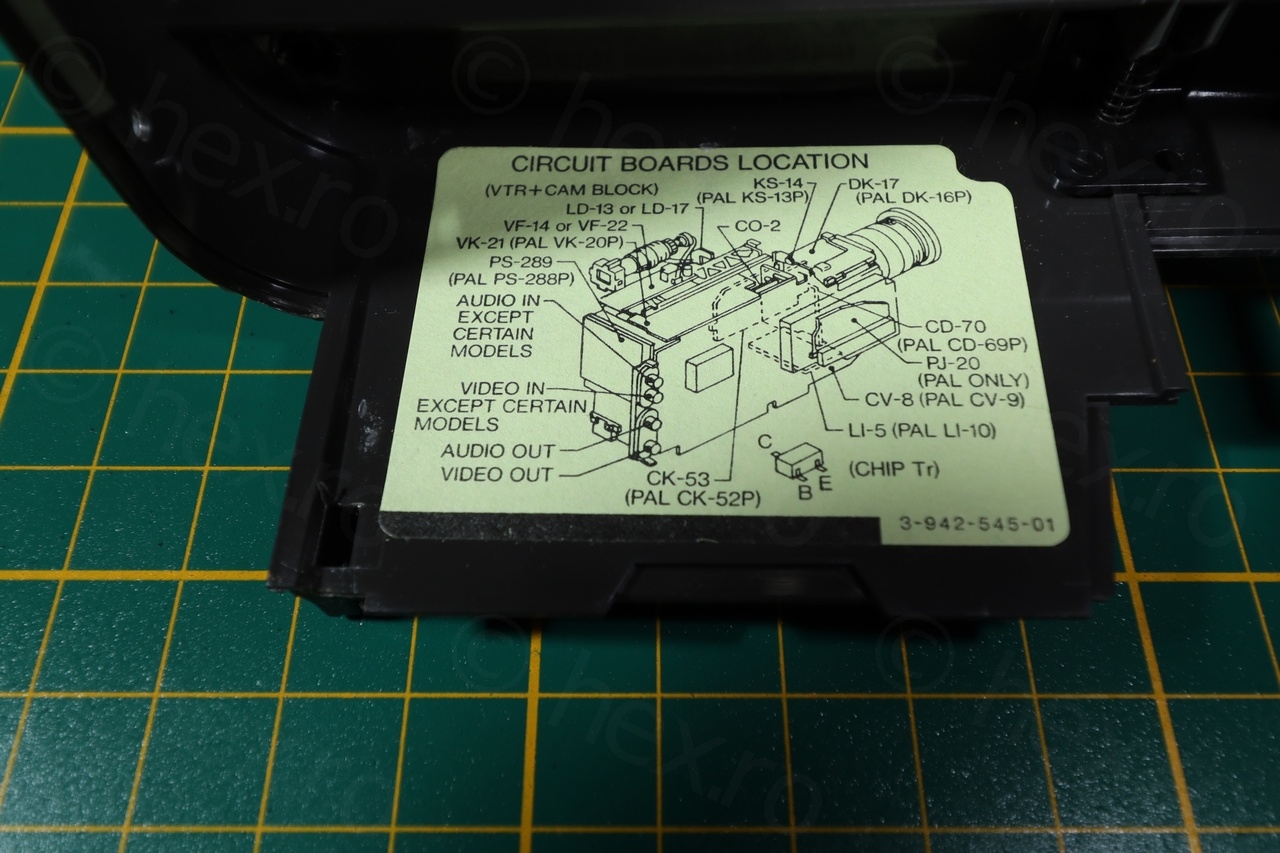
Camera looked clean inside – there was even a small diagram of the circuit boards location. Date code inside indicate March 1991 as production date.

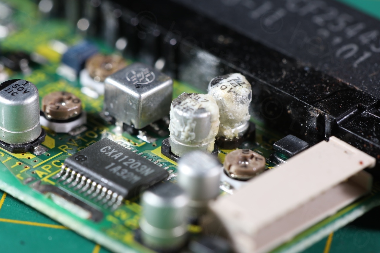
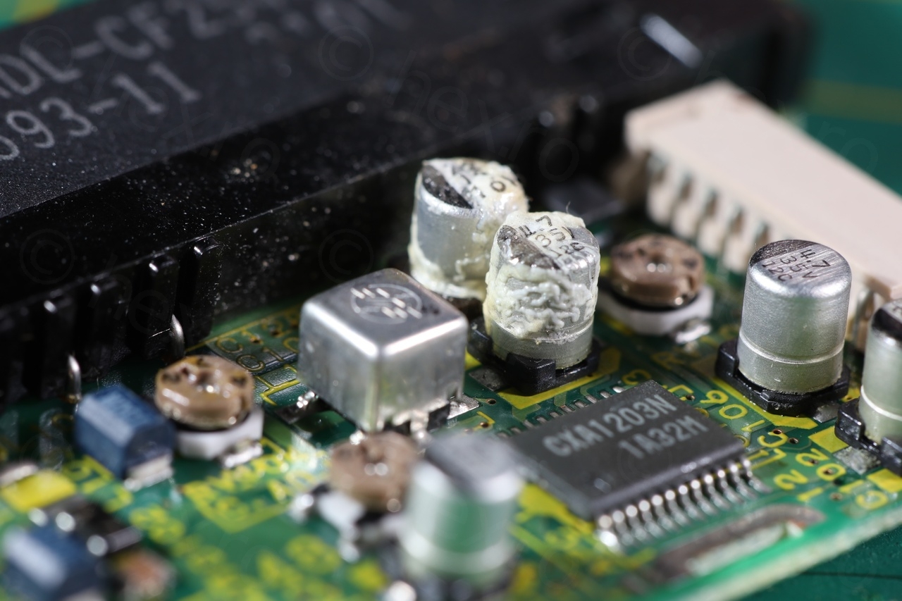
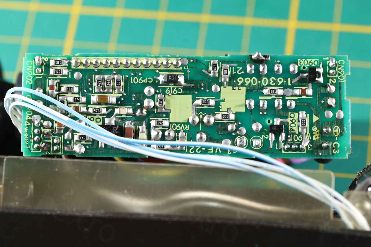
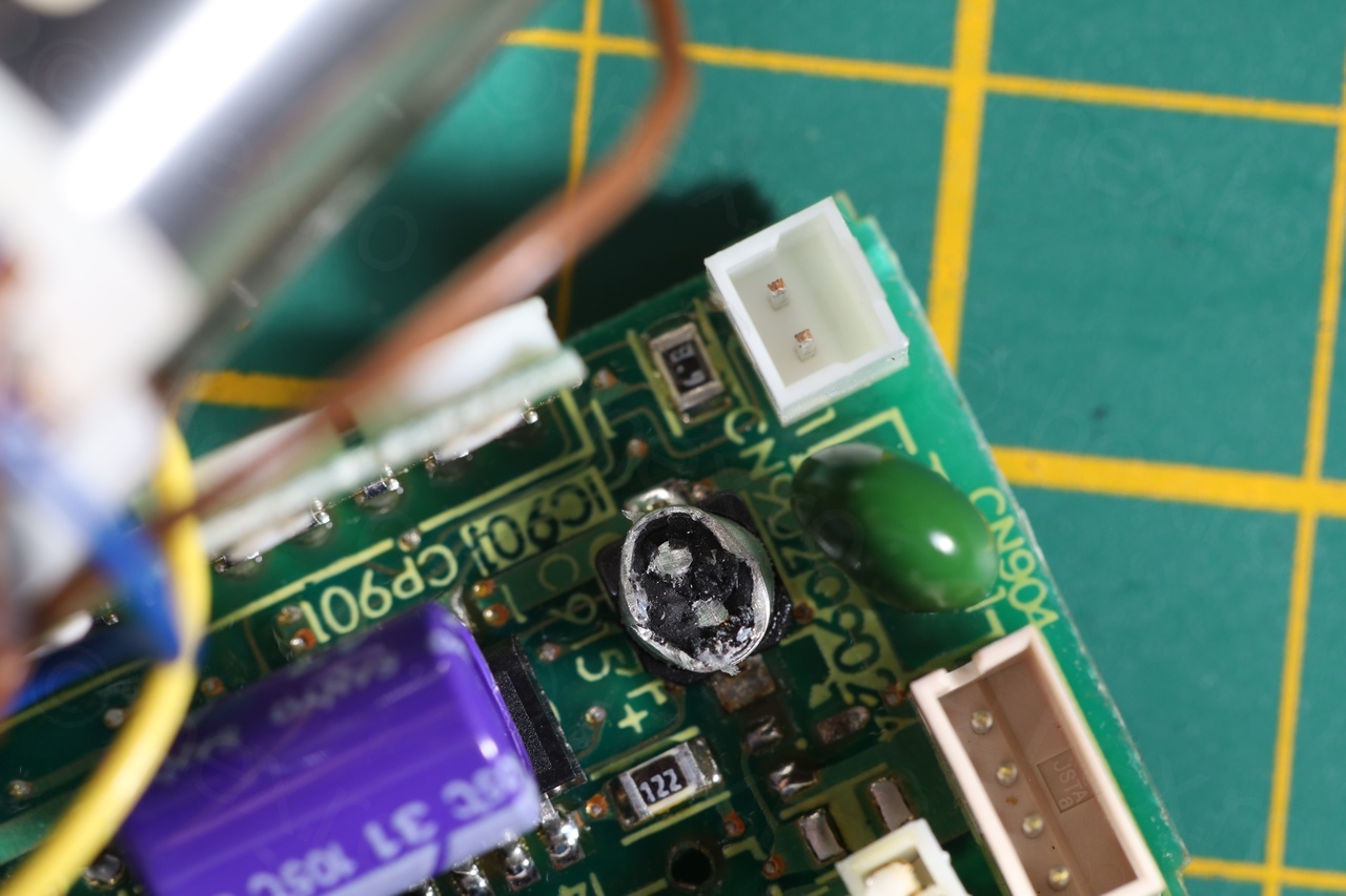
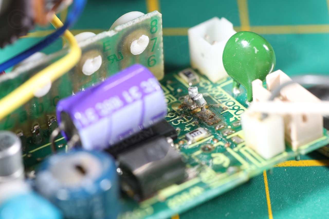
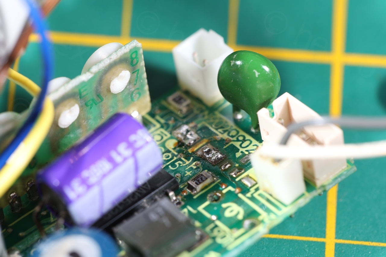
Two capacitors drew were screaming for attention though. SMD type, situated on the Analog Delay Line board:
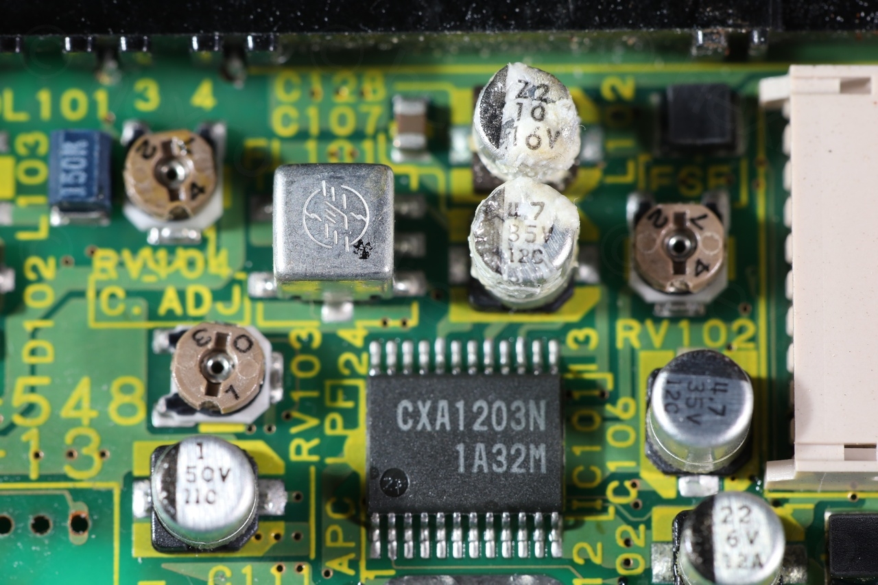
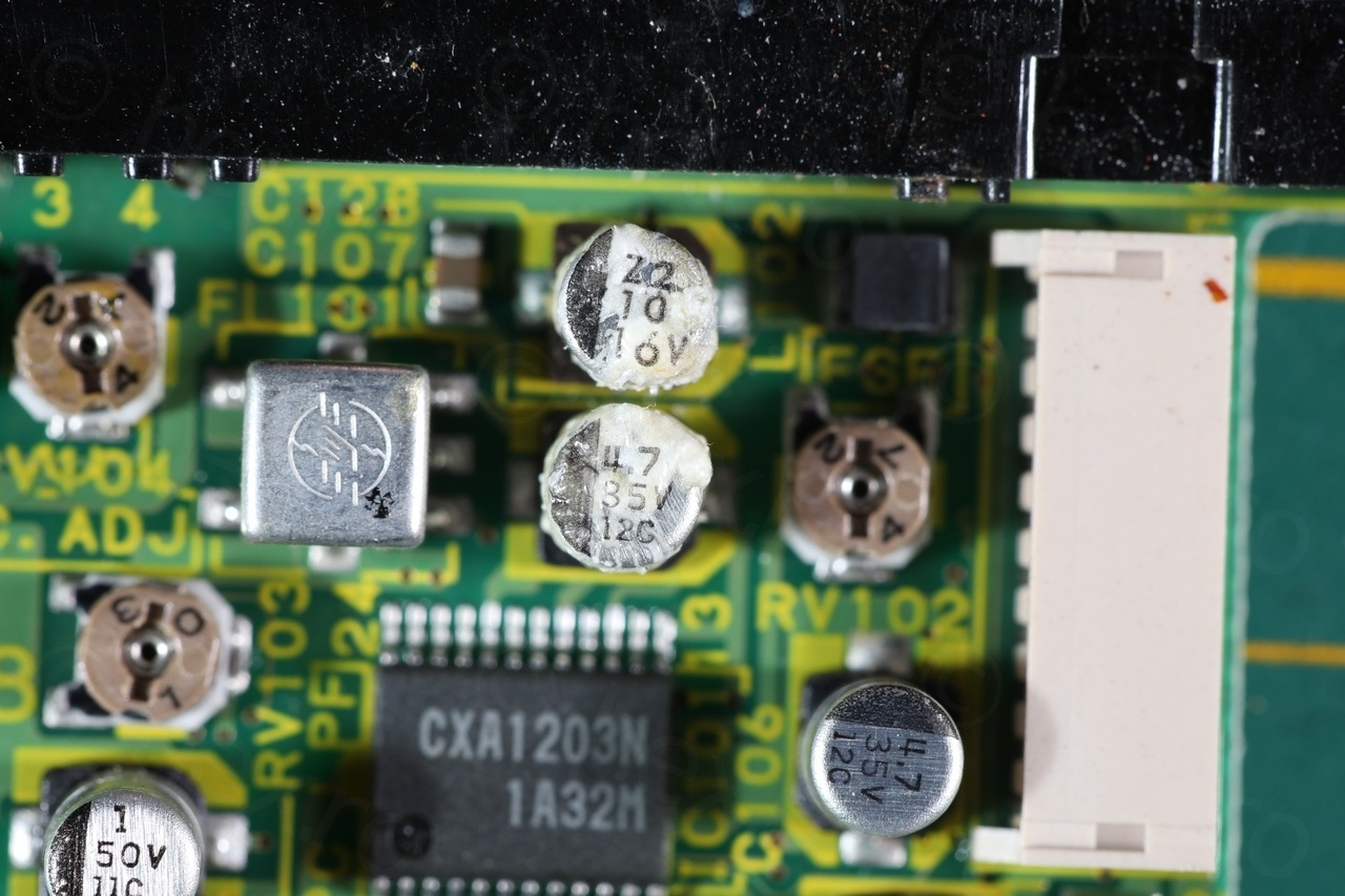
I decided to put them under the microscope.
Sony CCD-F355E – Capacitor with white deposits (microscope, 4x)
The deposit looked crystalline, and I never saw this type of white deposit on a capacitor. No other caps were affected – I was considering what if this was liquid damage ? Only these two were ‘dressed’ in white, all others were clean.
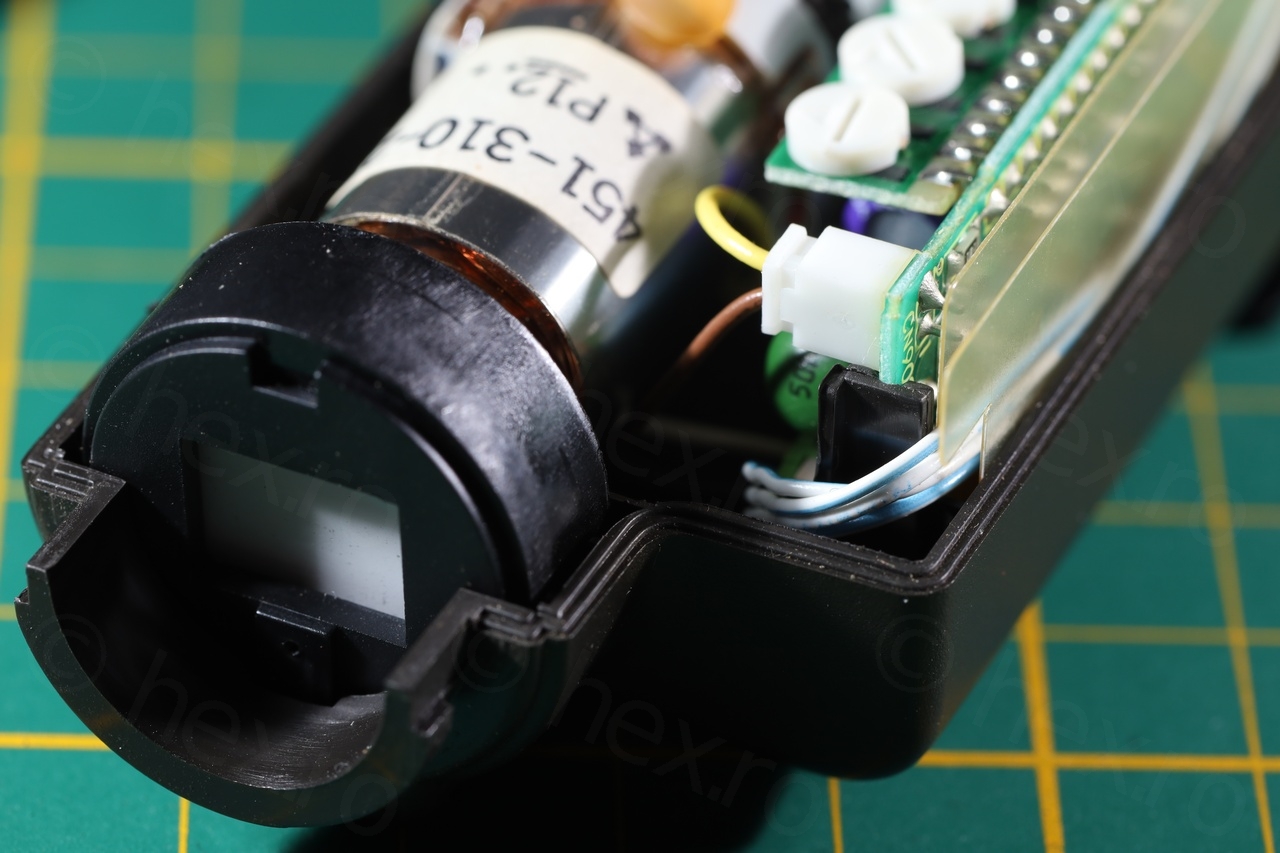
Electronic View Finder
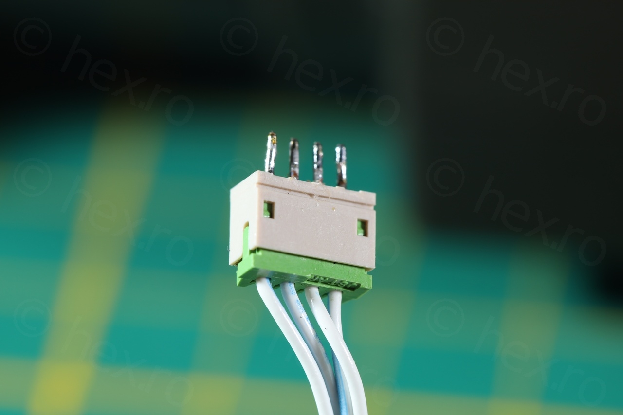
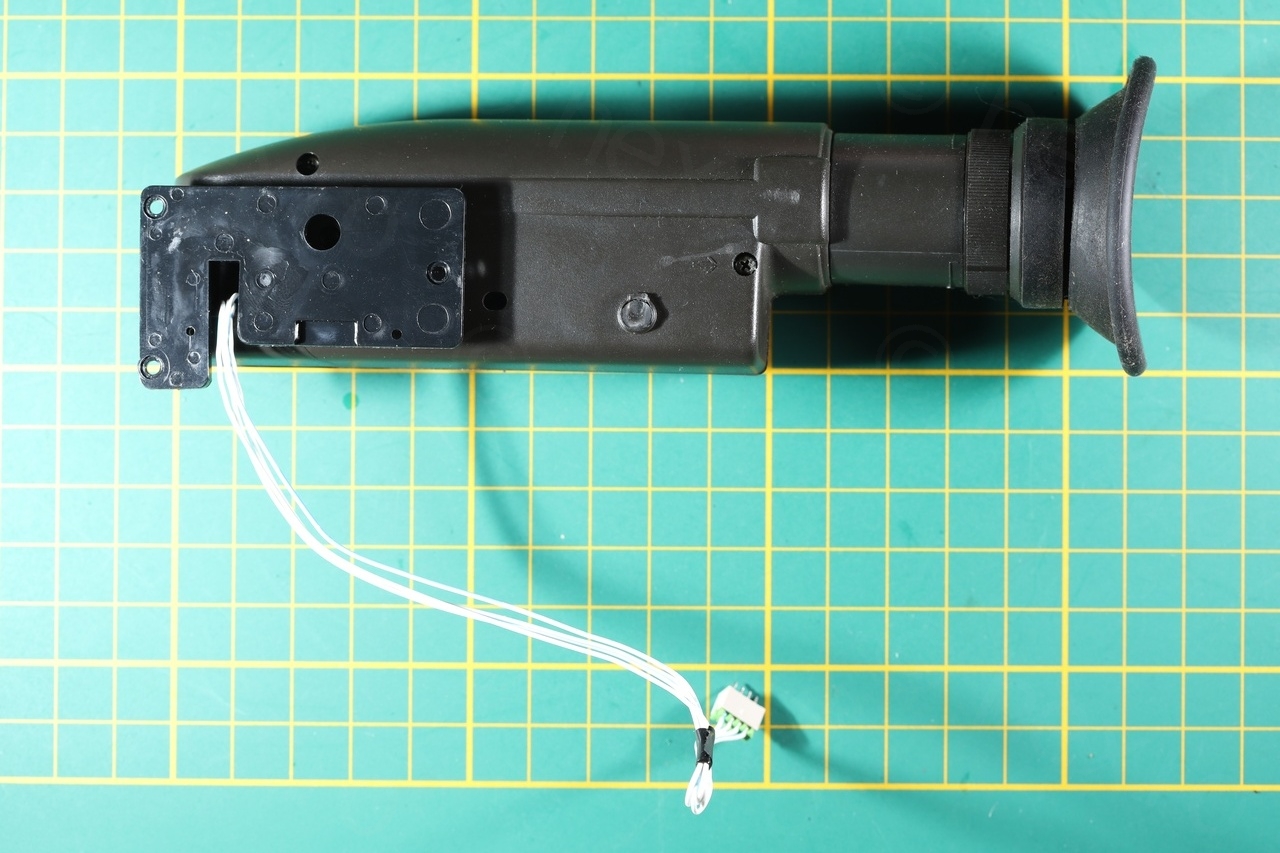
The camera had the VF-22 board inside the View Finder (one of the options listed in the Circuit Boards diagram above) – and 4 wire connector to the camera. I de-soldered the connector inside the camera – this would make it way easier to add test signals later on using small clamps.
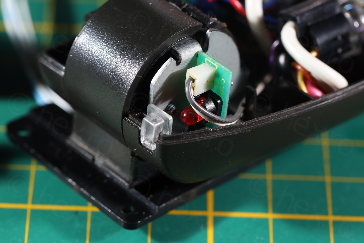
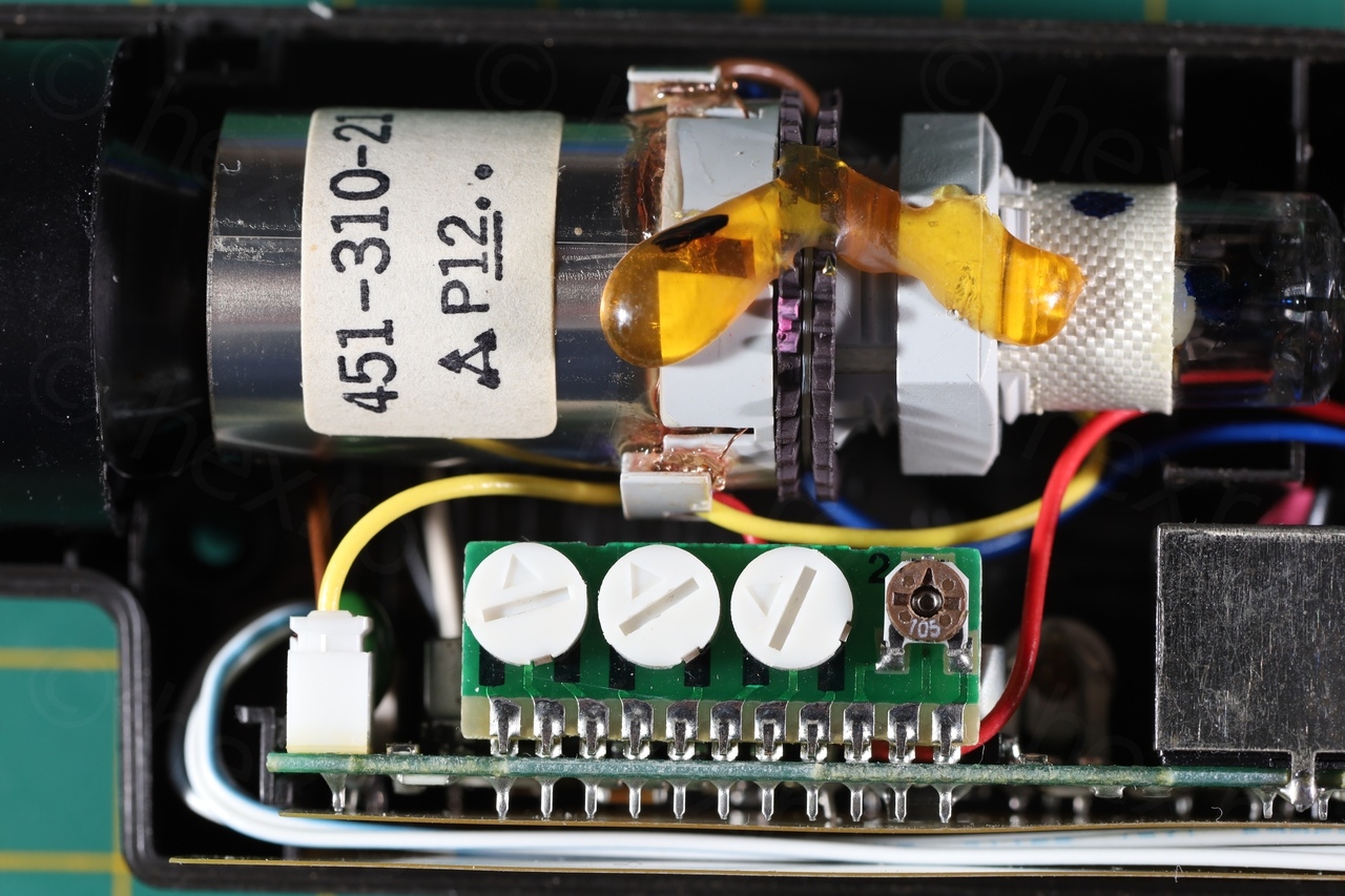
Close up photos inside the EVF unit shows a clean board. There are two RED LEDs (one just under the CRT, and another one to the back of the EVF) to indicate that the camera is recording.
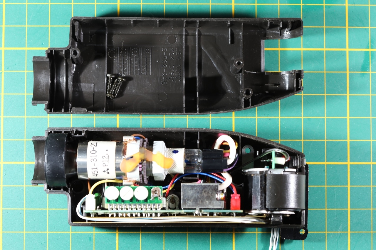
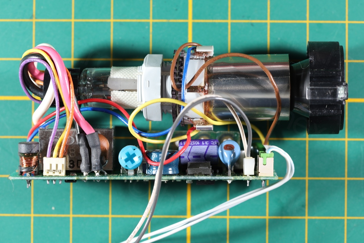
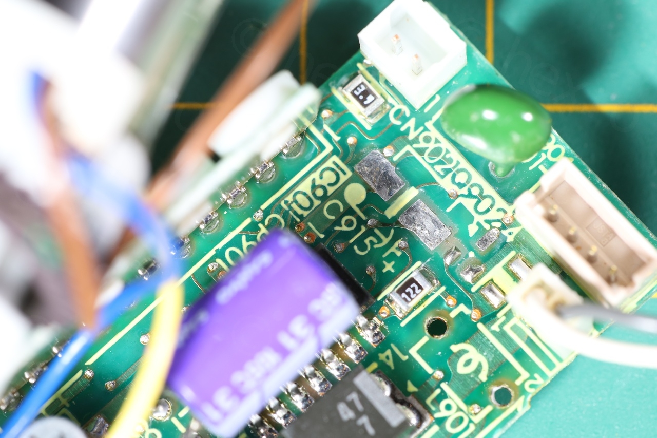
It is using an AN2512S CRT Driver IC – but it was hidden underneath one of the capacitors:

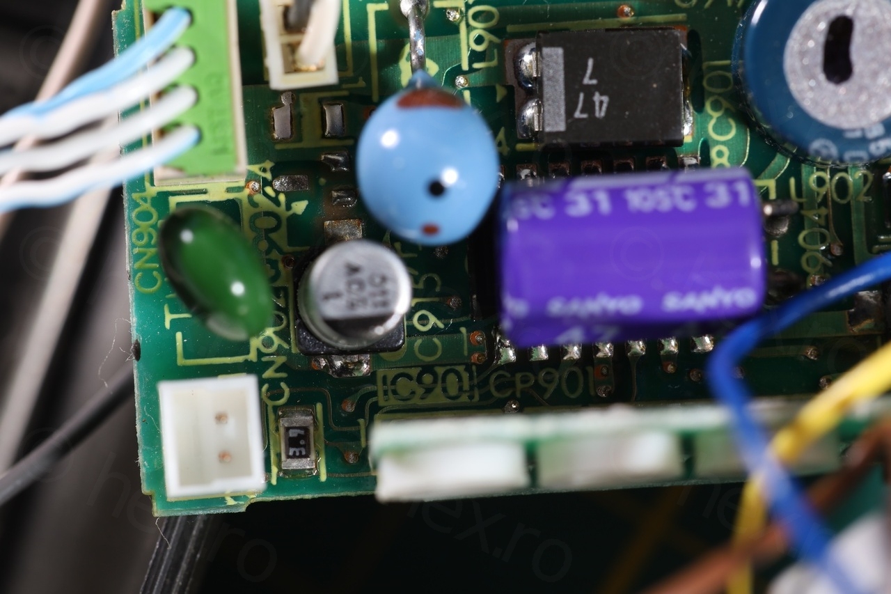
Identifying the power pins was easy, the exterior of the Fly Back Transformer is connected to GND, and the only other pins of the FBT that have continuity to the connecting cable of 4 wires are the VCC pins. However, the image was bad. The vertical alternating lines were clearly visible:


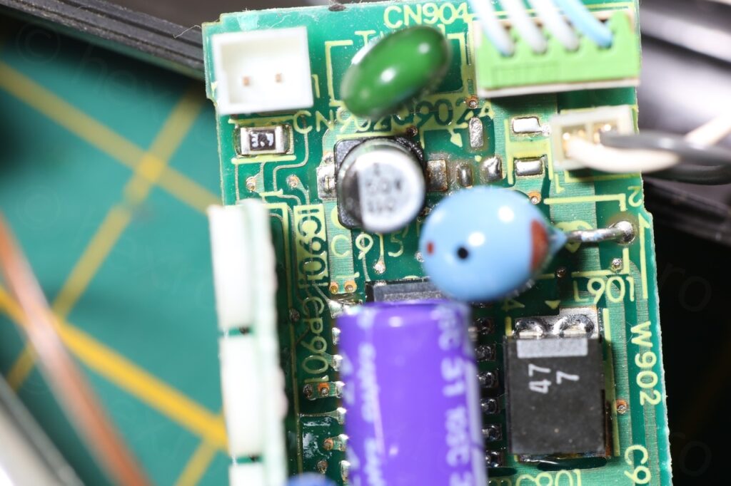
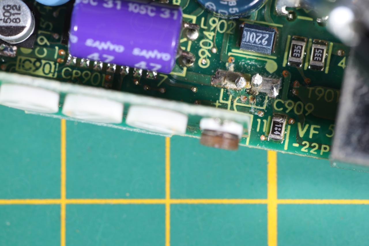
None of the capacitors were testing properly in circuit using the ESR meter. They were reported as In Circuit / Leaky but I decided to focus on the SMD ones (two of them, both 1uF @ 50V).
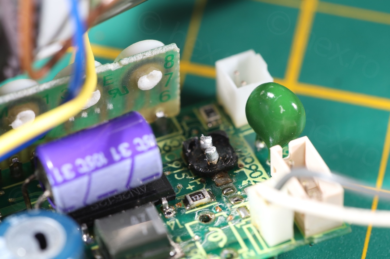
One of them looked like it leaked, one of the pads (the positive one) look faded and yellowish:
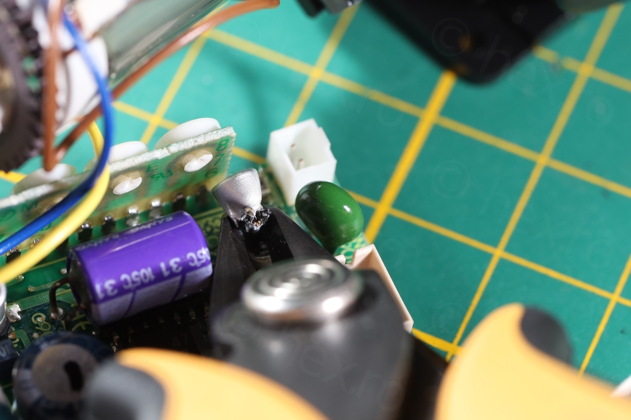
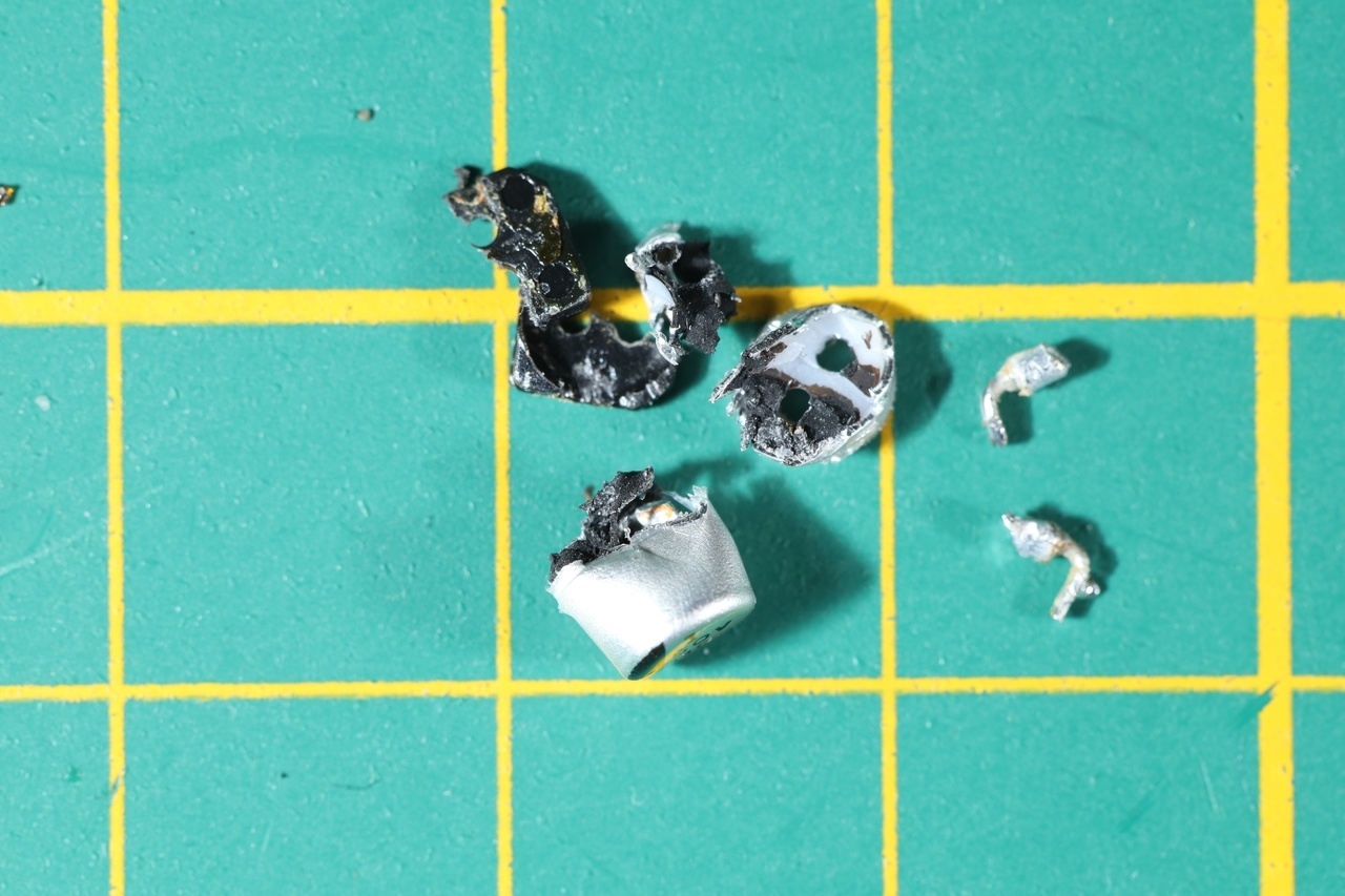
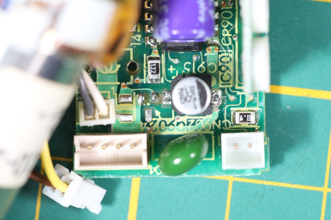
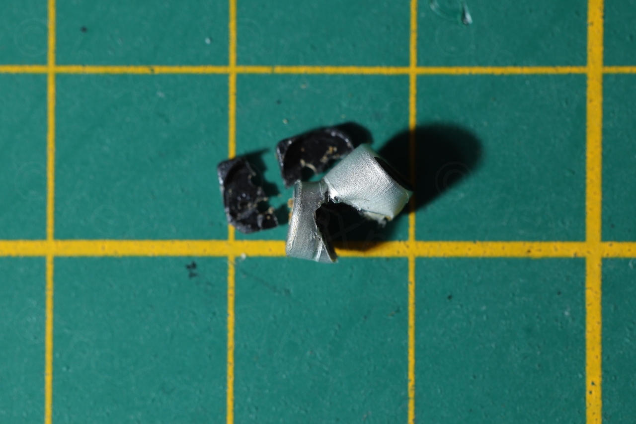
Access to the cam was hard, so I decided to remove the big blue inductor and then cut the capacitor away, desolder the remaining pins and install a new capacitor:
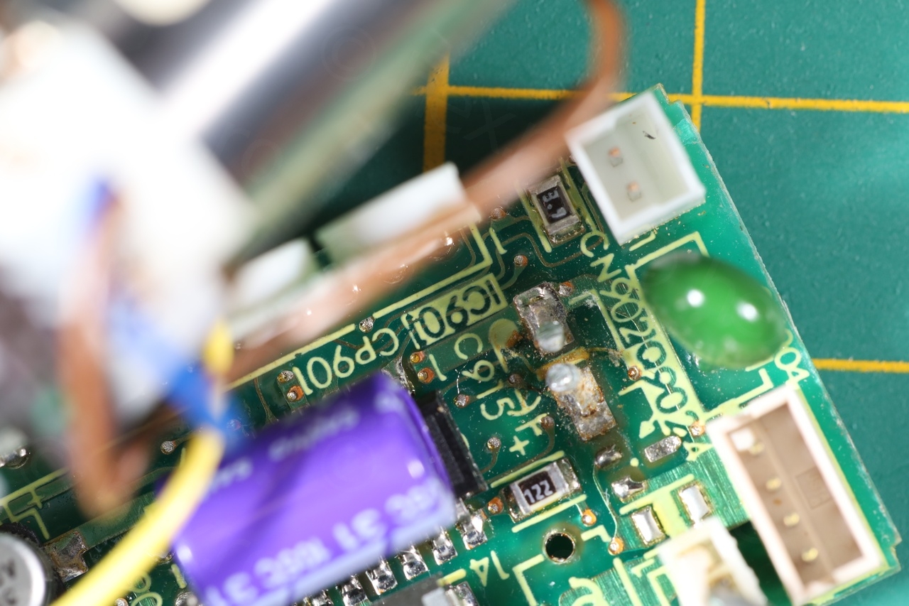
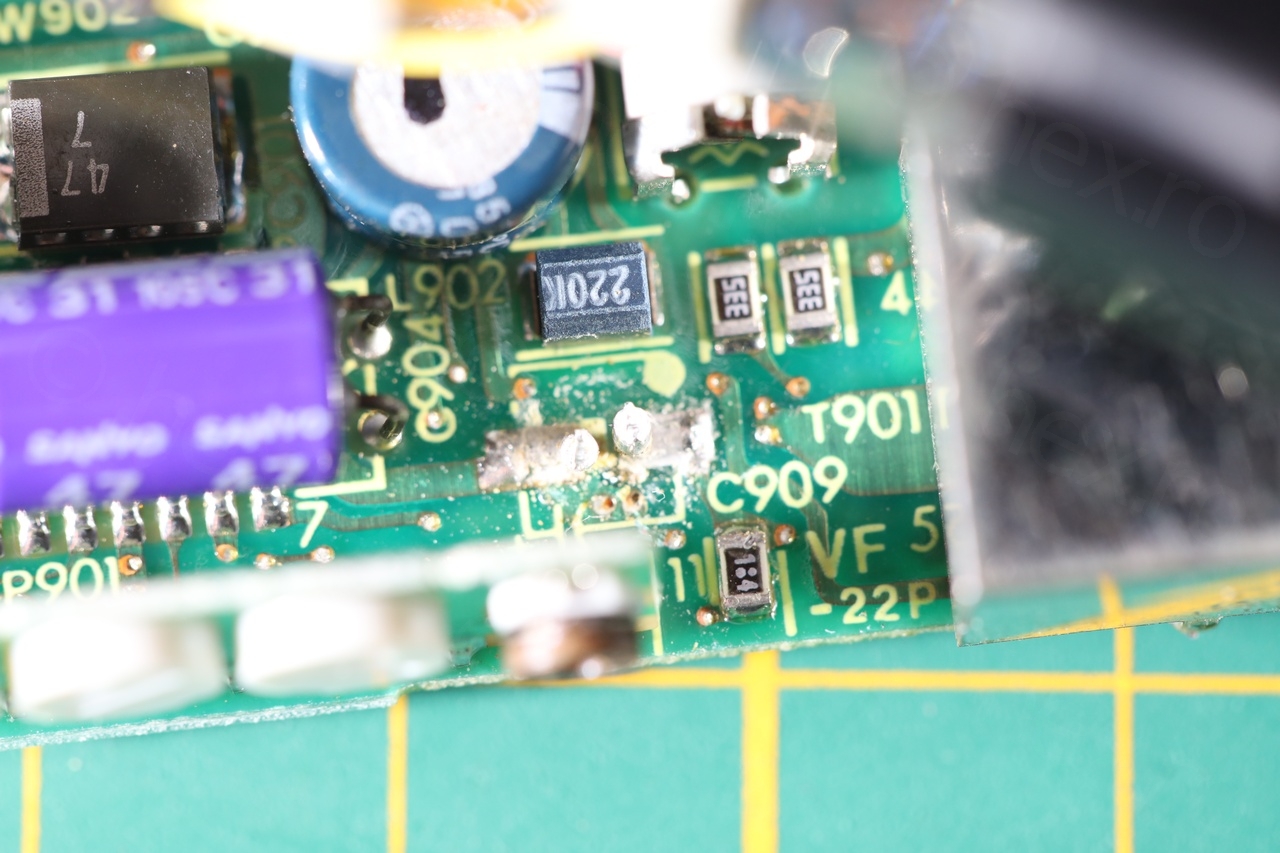
After soldering back the inductor and powering on the board, disappointment, the image still showed the alternating vertical bars, although the pattern was slightly shifted to the right – the thin white line on the left is no more:
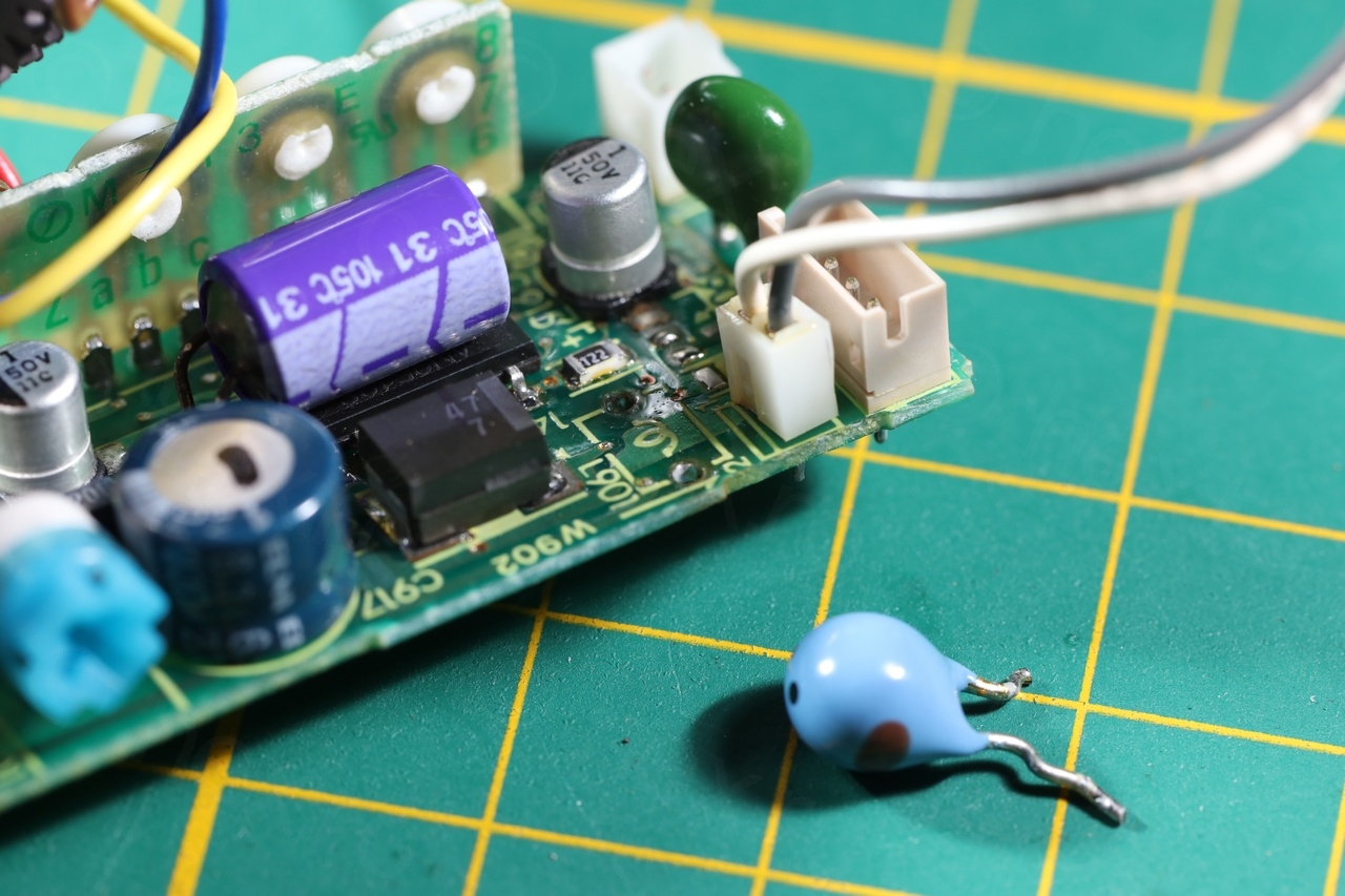
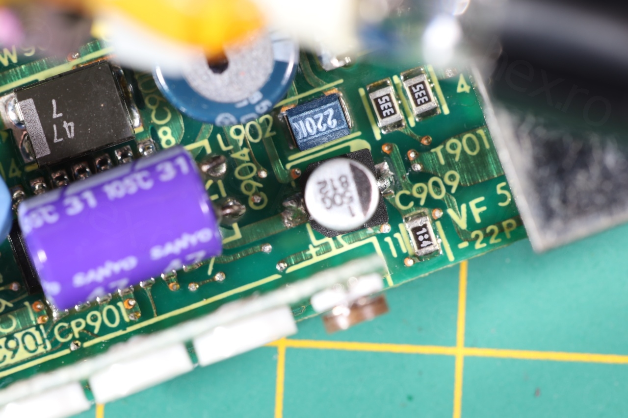
Since I did not have replacements for the normal electrolytics (non SMD), I decided, in Shango66 style, to just bridge a 10uF capacitor across their pins – to see if there’s anything changing on the output. And surprise surprise, bridging the second SMD capacitor cleaned up the image perfectly !!
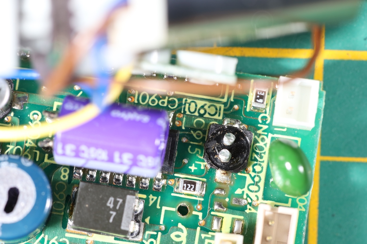
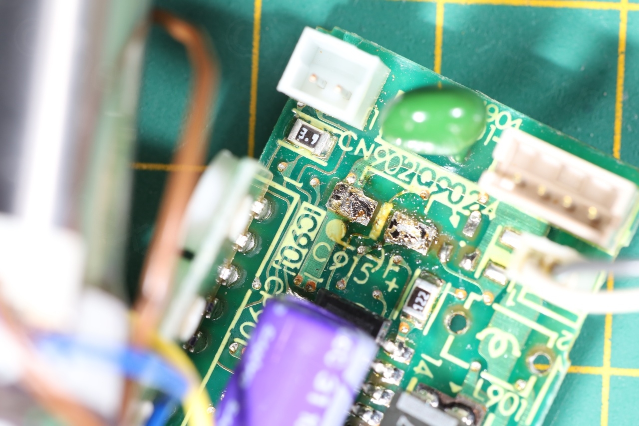
So off to replacing it too, another 1uF @ 50V:
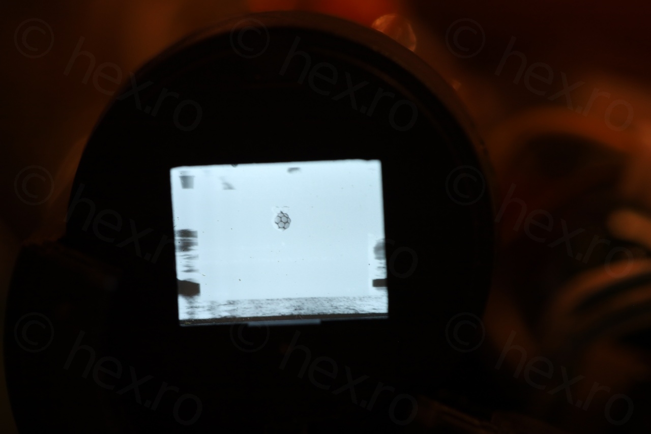
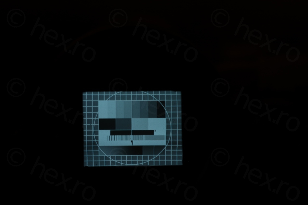
Now the image looked perfect – no more vertical bars. After a bit of trial and error I have identified the 3rd pin, the VIDEO IN signal:
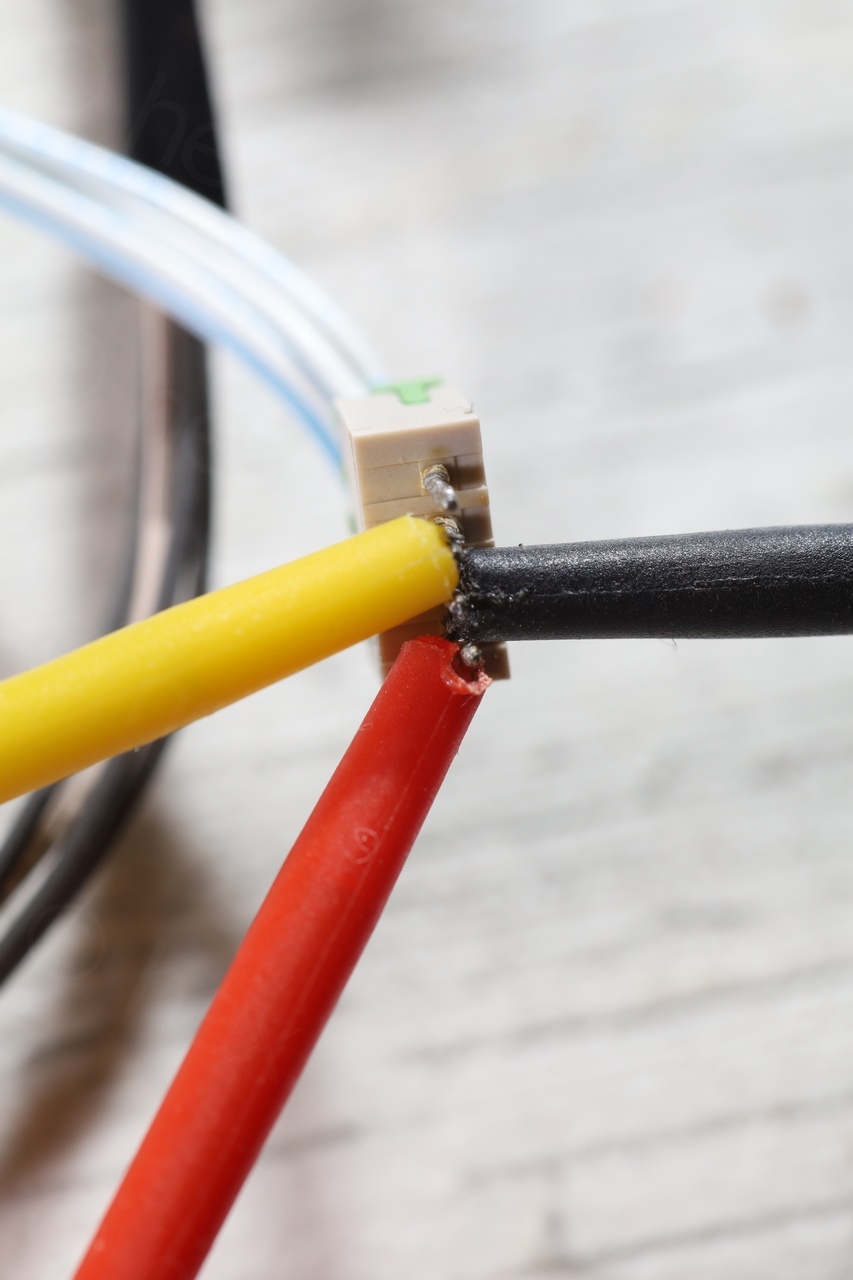
The 4th pin (active low) controls both the RED recording LEDs.
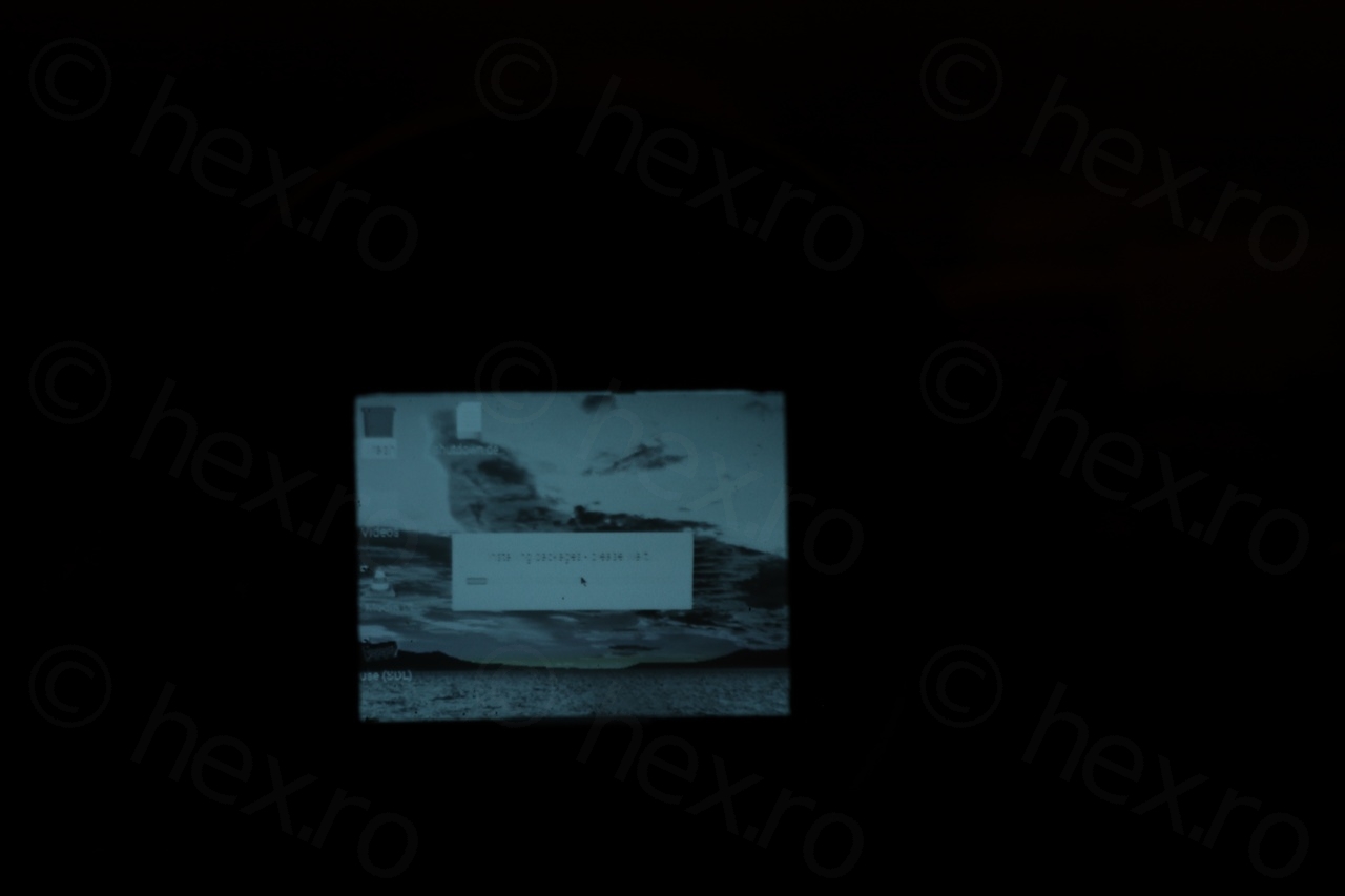
Image now looked almost perfect. I noticed a bit of the whites that were ‘smearing’ to the right (especially in the high contrast areas):

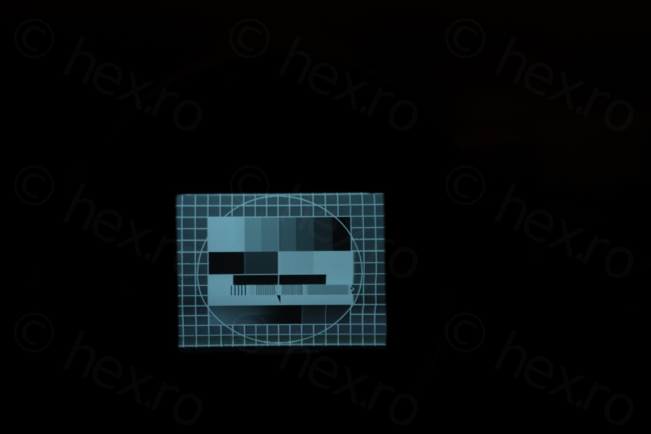

It seems that by adjusting the contrast everything fell back into place:

In conclusion, I am left with a sour taste after having to fiddle with these bad SMD capacitors in such a tight place. However, CRT is sharp compared to others – and not so much distortion. Happy I saved the driver board, and looking forward to a new CRT that hopefully won’t pose so many problems.
Leave a Reply