


Introduction
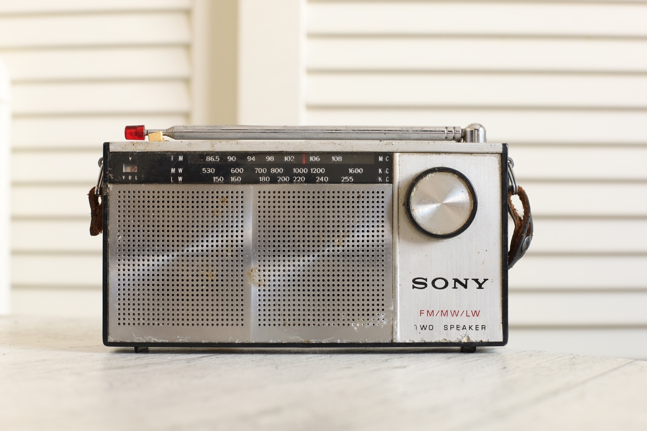
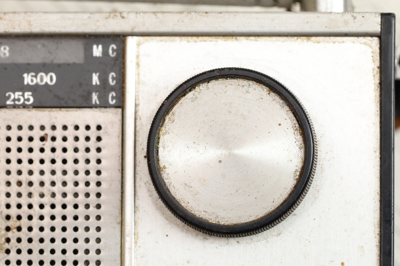
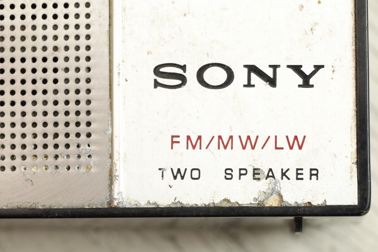
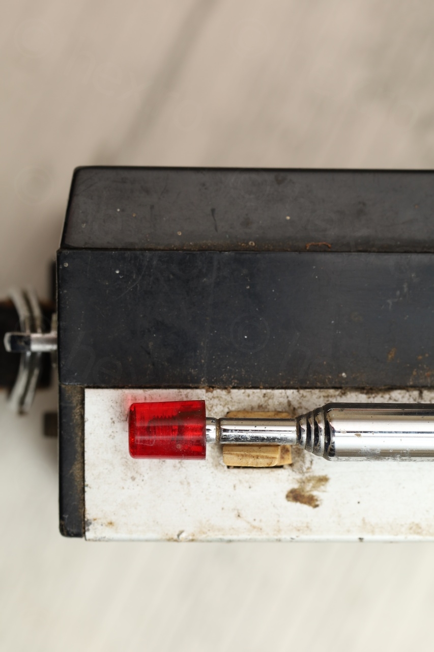
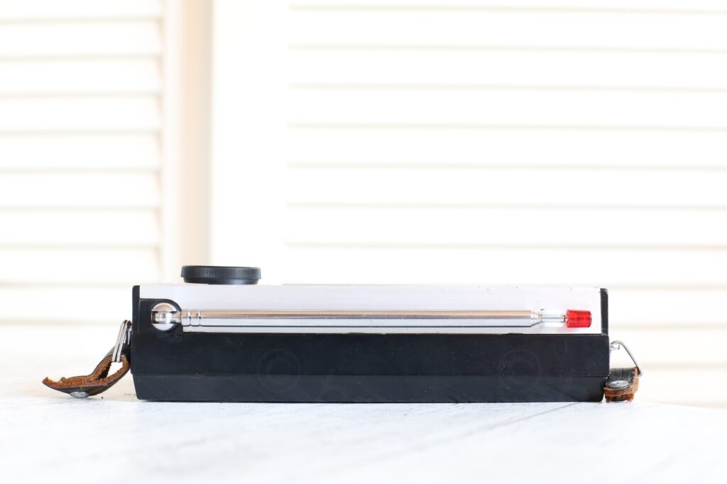
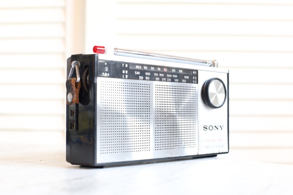
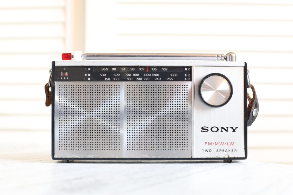
I bought this radio at a local flea market. Something about its block-y design drew my attention, the front was taken by the large dual speak grill and the tuning knob. The dial scale is low contrast and occupying a small area on the top of the radio face, as if it is a shame to draw attention to it. The band switch, 3 audio jacks as well as volume pot are hidden to the sides and back, they too unimportant enough to take away from the front view. Only two small red highlights – antenna tip and the dial of the volume potentiometer visible through a tiny window.
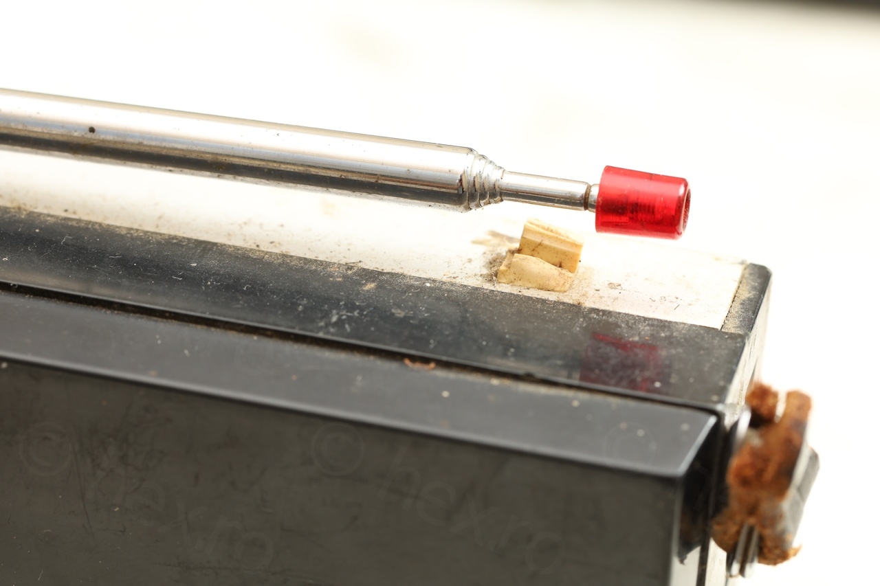
While front design of radio was impressive, the visual aspect was extremely poor. Visible signs of corrosion, rust and thick dust and the remaining stump of the antenna holder were turn offs, but the design impressed me enough to justify the purchase and the effort to restore it.
This became a quite involved process, requiring 3D printing to salvage the radio while conserving its initial appearance.
General aspect
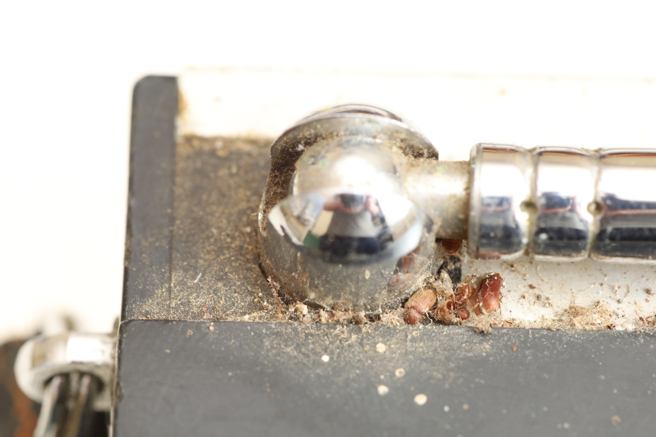
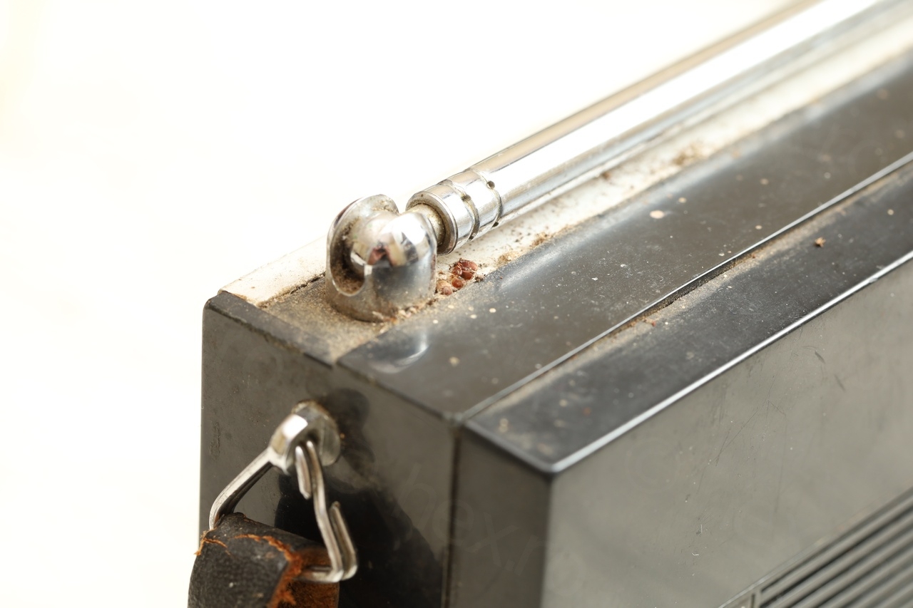
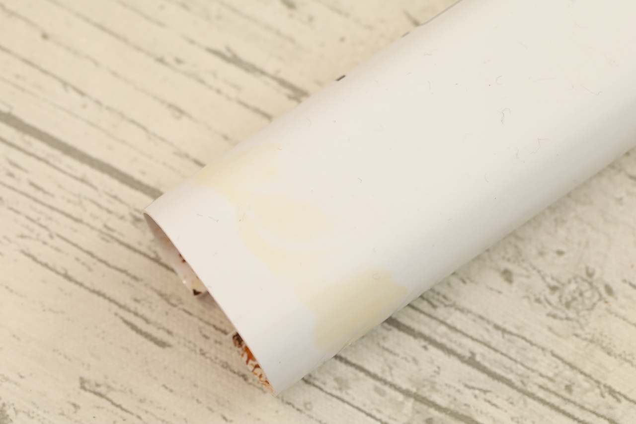
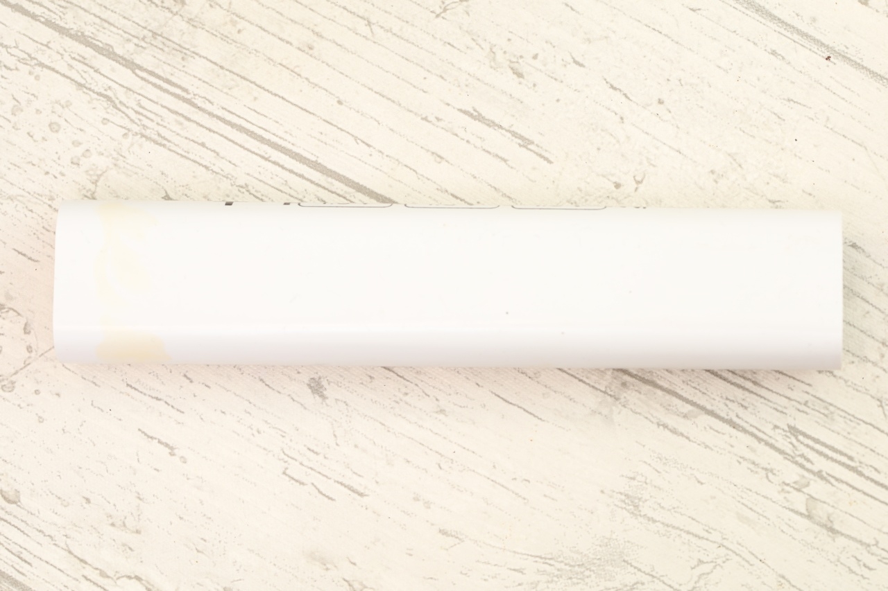
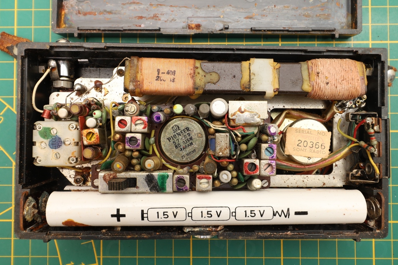
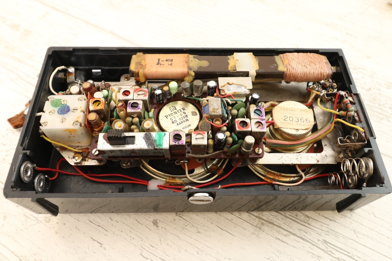
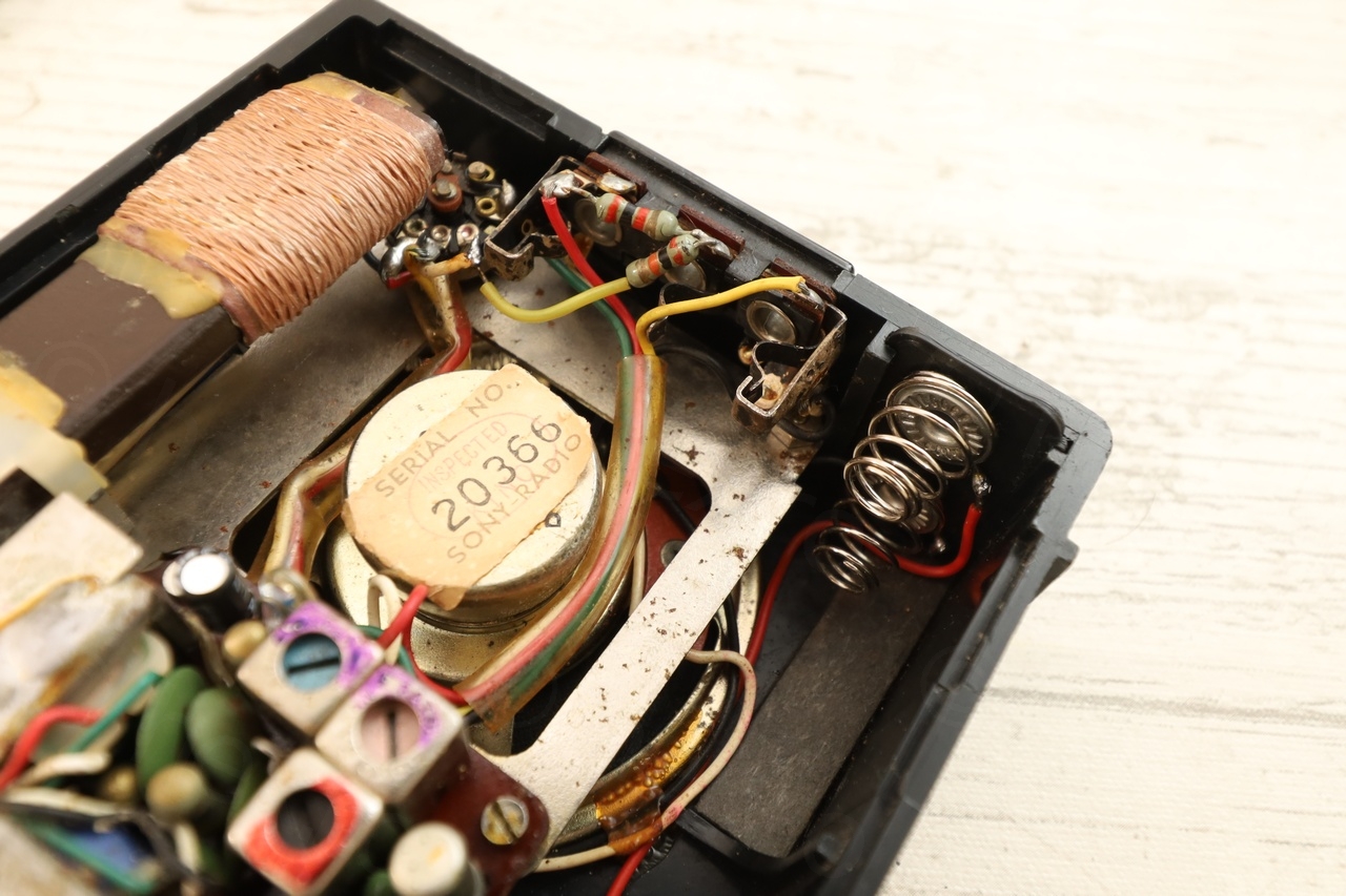
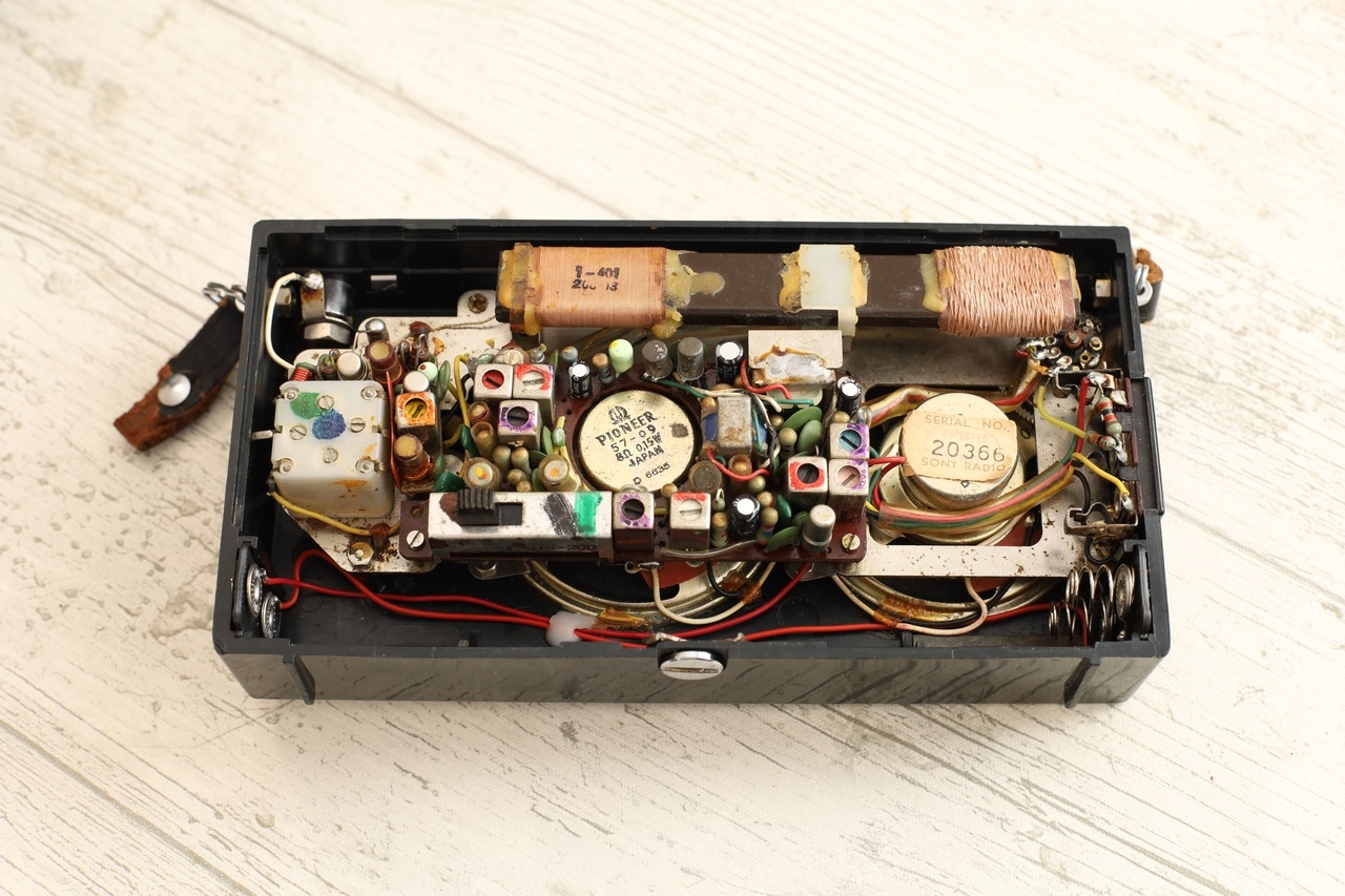
These are some of the initial photos showing the its initial state:

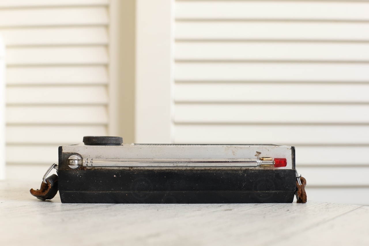
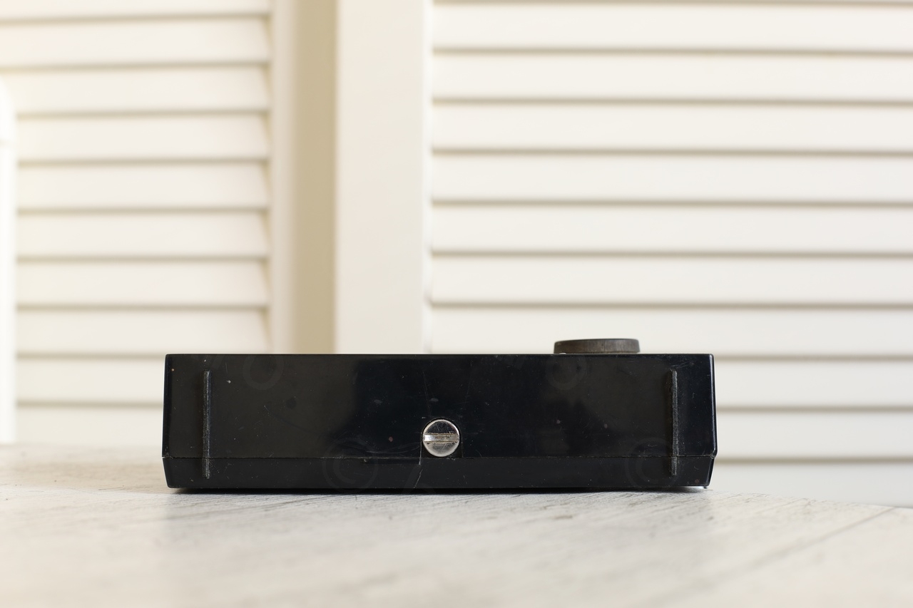
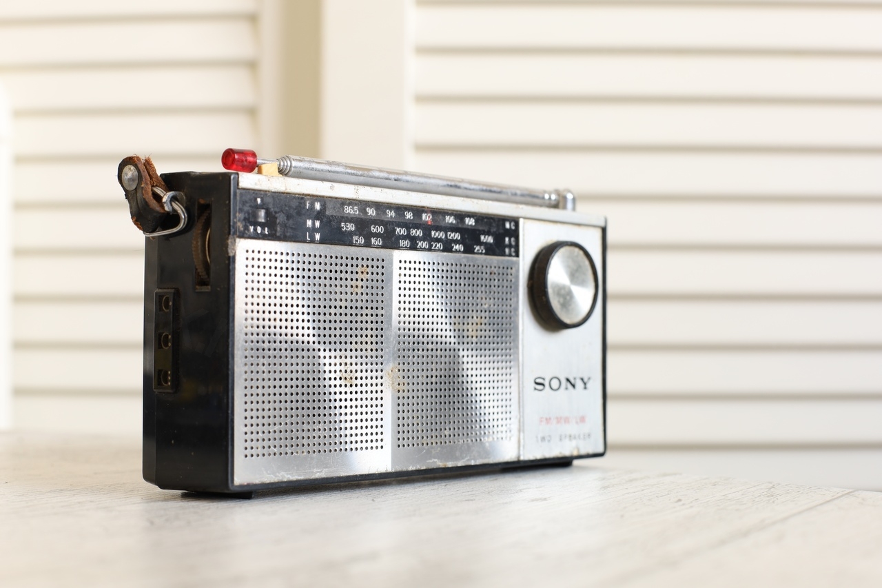
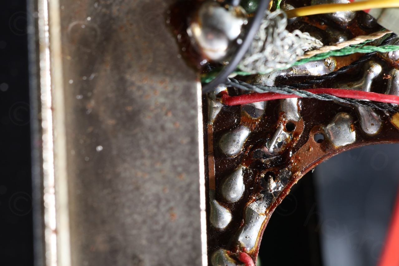
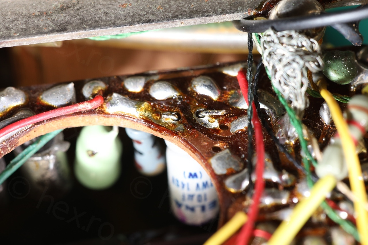
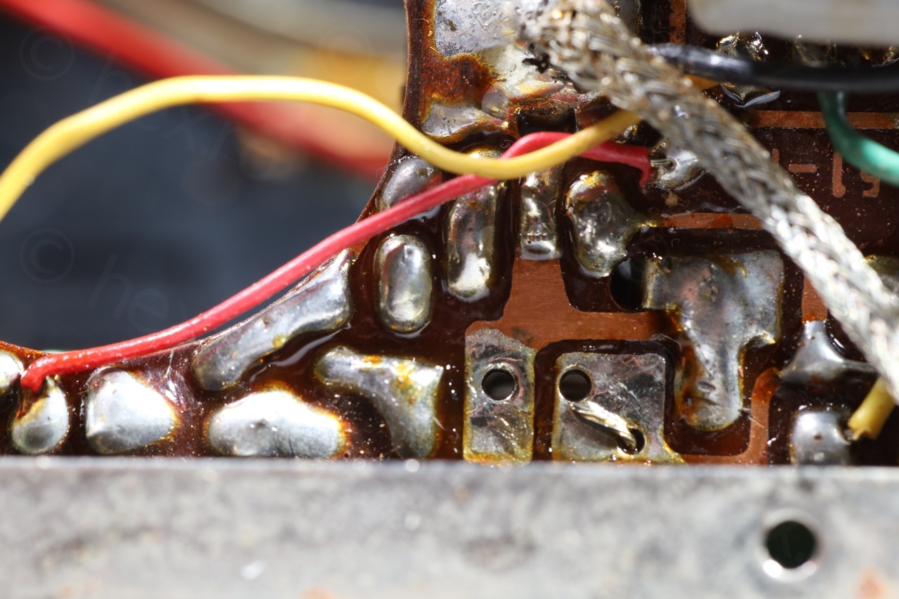
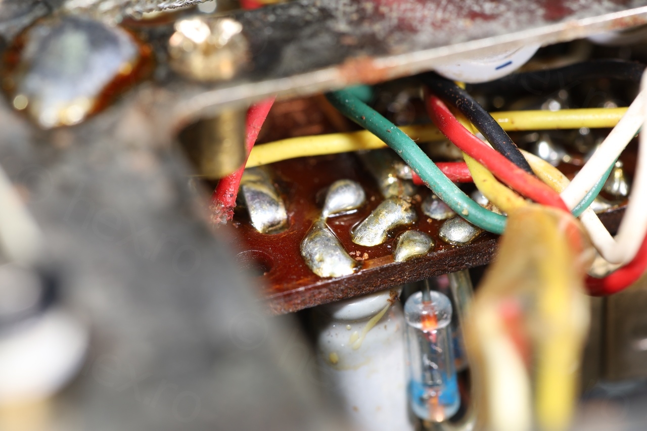
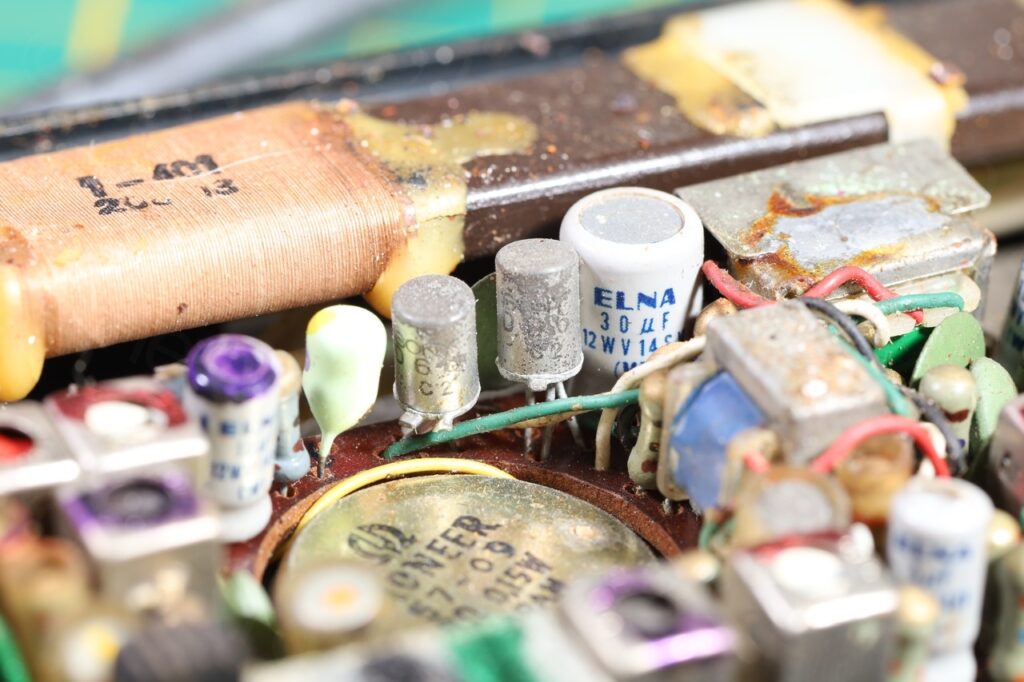
Some more close-up photos I took to record the initial state:


Cleanup
The first step was to clean up the dirt and what seemed to be dead bugs – at least so that I could work on the radio electrically. As there were issues here too but on these, a little lower.
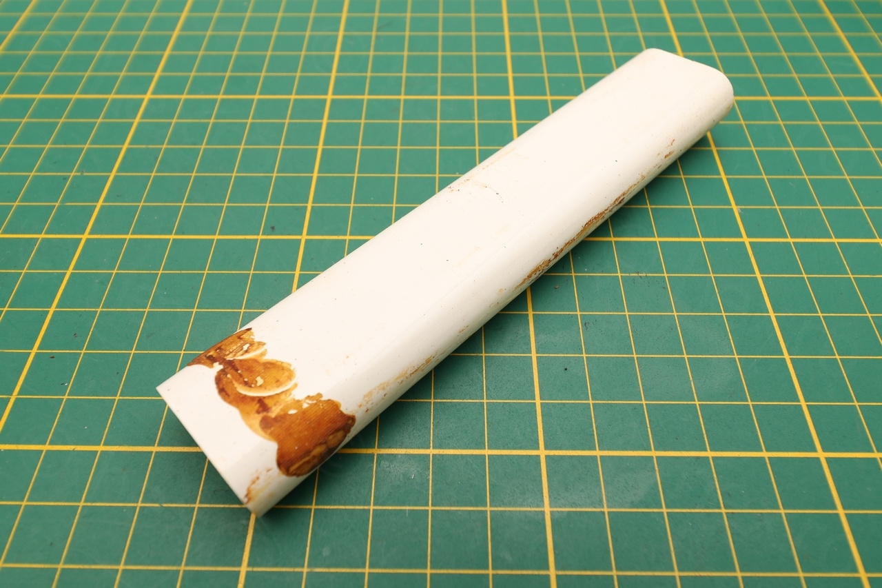
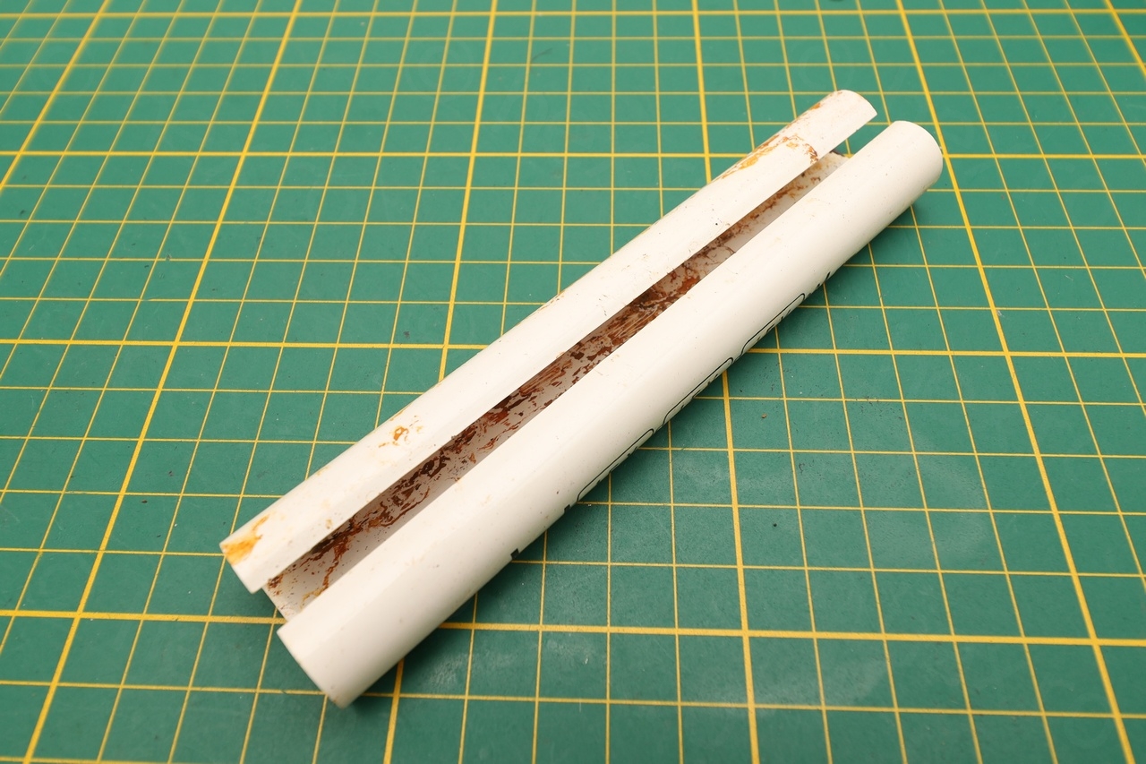
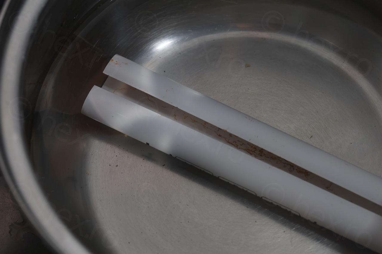
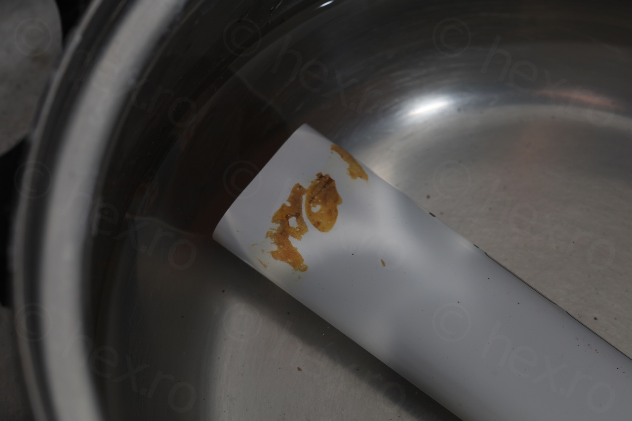
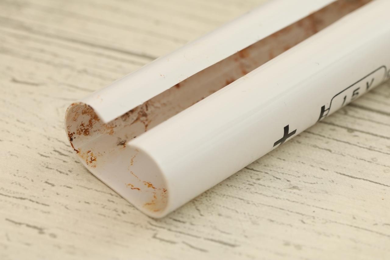
The hardest part to clean was the battery holder plastic, as it was full of some very hard brown substance. I tried both baking soda as well as leaving it 1 day in vinegar, but it was still very very hard and encrusted. I was able to force it apart on the exterior of the holder using toothpicks, since anything metallic would have bitten too much on the fragile plastic. I could not get inside though to apply the same pressure, so I left it as is ..
I scrubbed also the case of the radio, the grooves of the volume / tuning knobs, cleaned the dust with baby wipes, the rust with IPA and tried to bring it back to shininess.
No volume fix
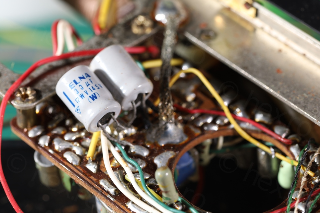
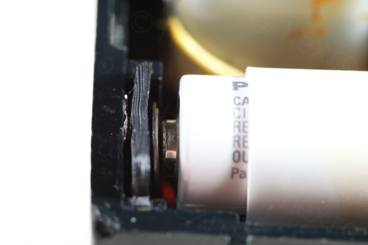
The radio suffered from very low volume no matter the band .. not to mention scratchy pot, but that was taken care by the contact cleaner. After looking at the schematics, the culprit seemed the capacitor after the volume pot, which was indeed open:
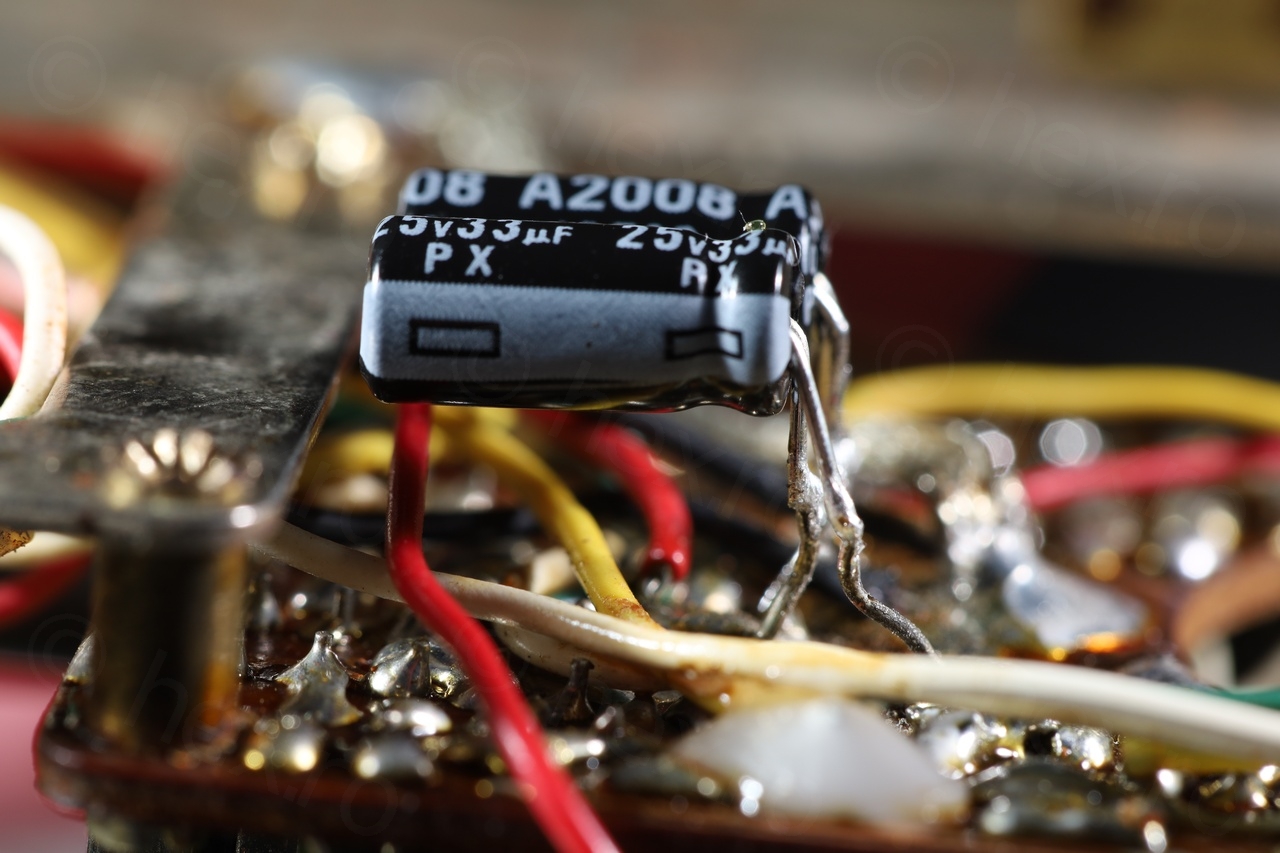
Putting another good cap in parallel restored full volume, so at least I was able to diagnose the radio without first recapping it. Although the interest was to keep the radio as close as possible to the original look, I did decide to replace all Elna capacitors. Few I could not properly measure in circuit, and one more also appeared open. In fact, the 30μF ones were reading about 45μF outside the circuit (although ESR was less than 3ohms) and another one was indeed open.
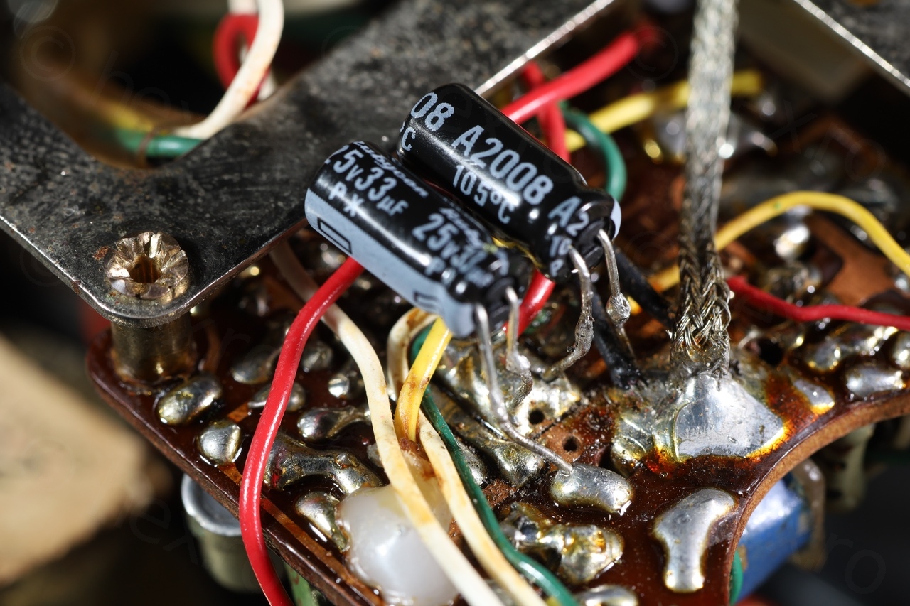
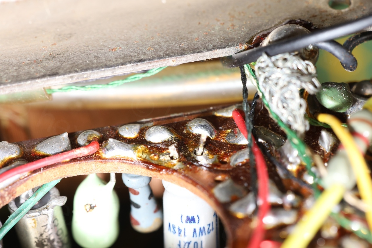
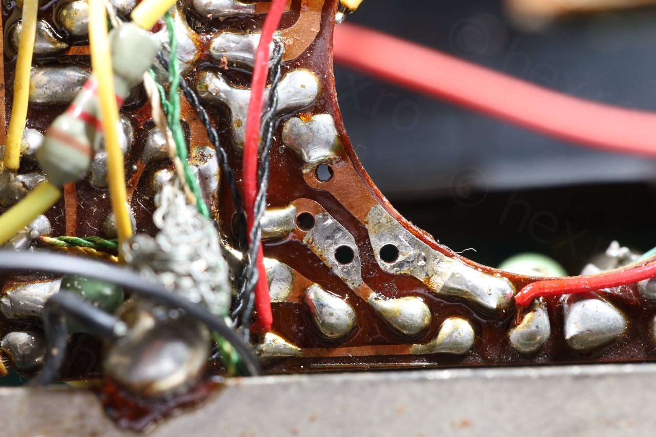
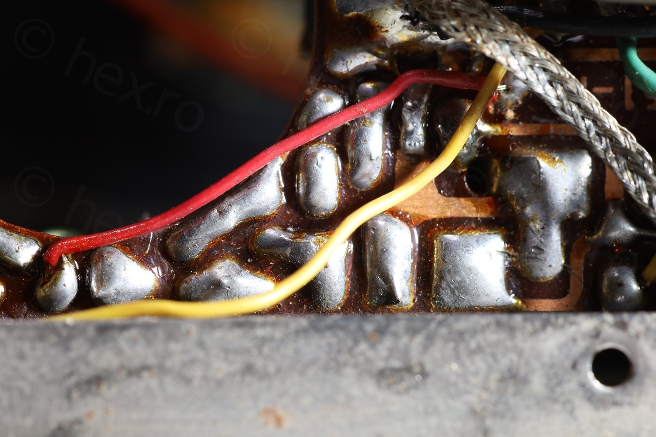
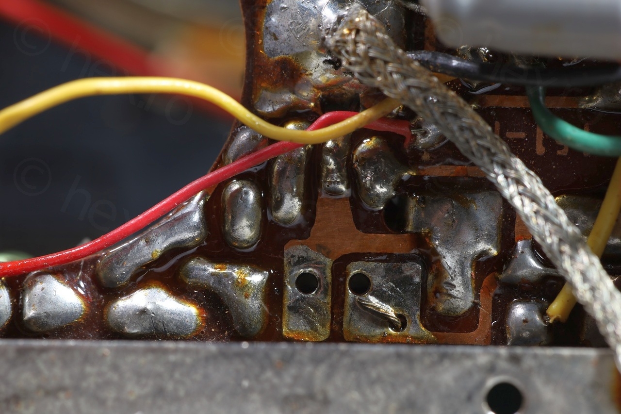
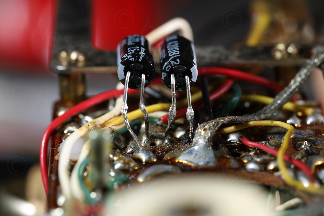
2 capacitors floating in air on the back of the circuit board and 4 more on the other side:
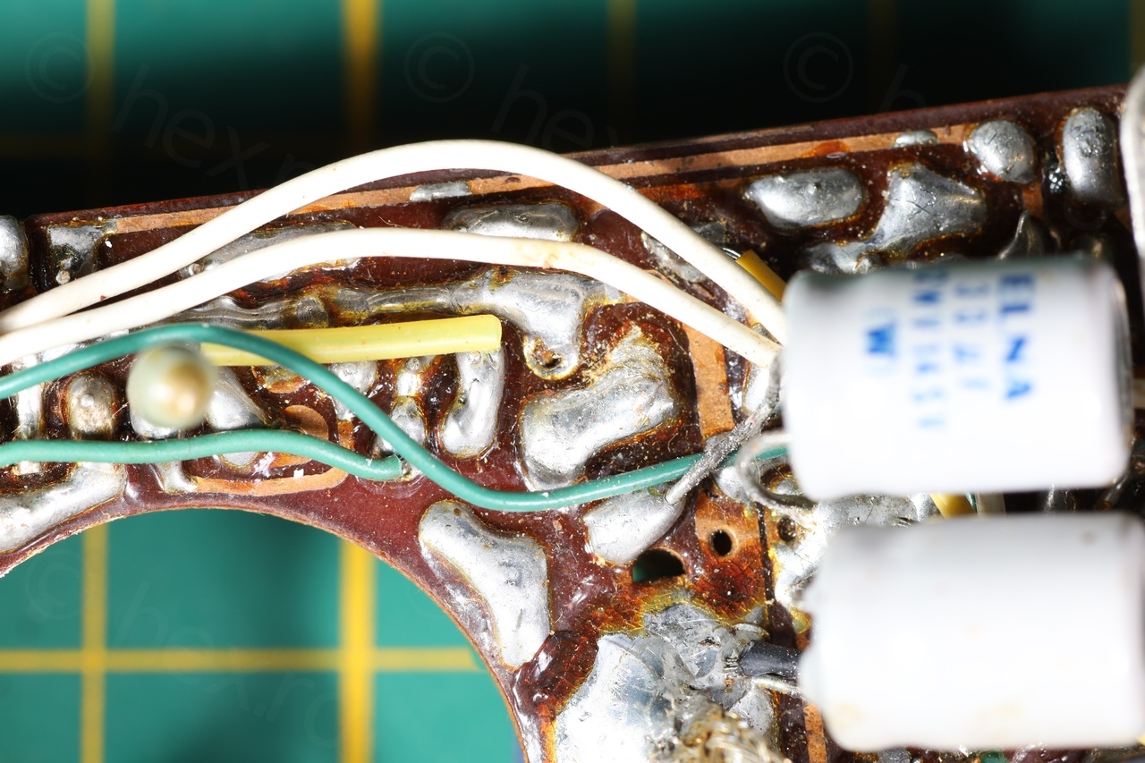
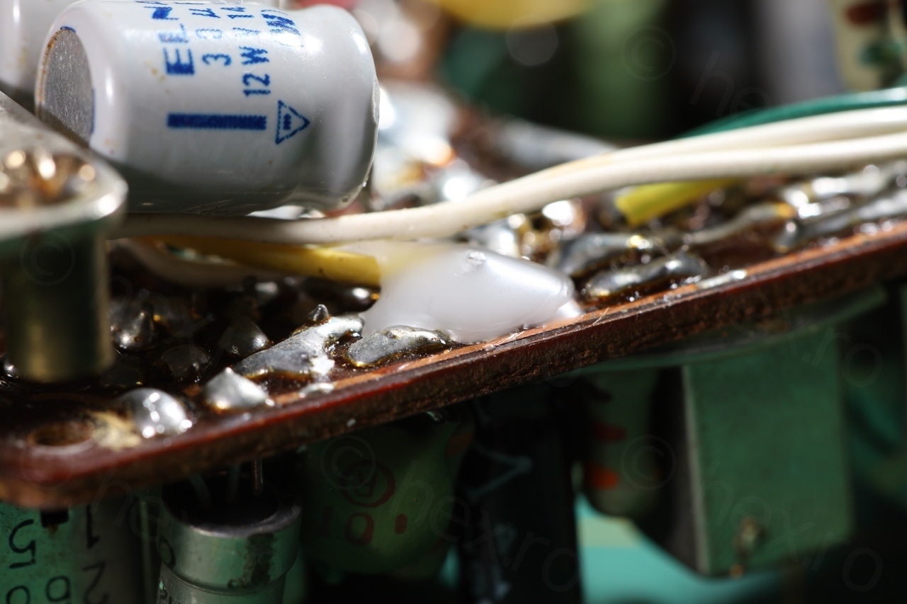
It was very tedious to access the radio without touching a lot of cables going everywhere. Unfortunately, one pad lifted and I used wax to hold the yellow wire in place.

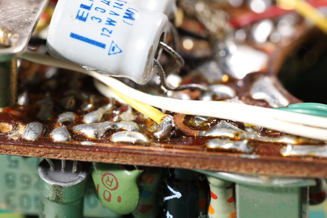
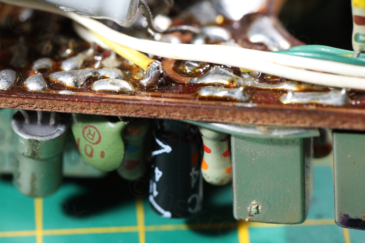
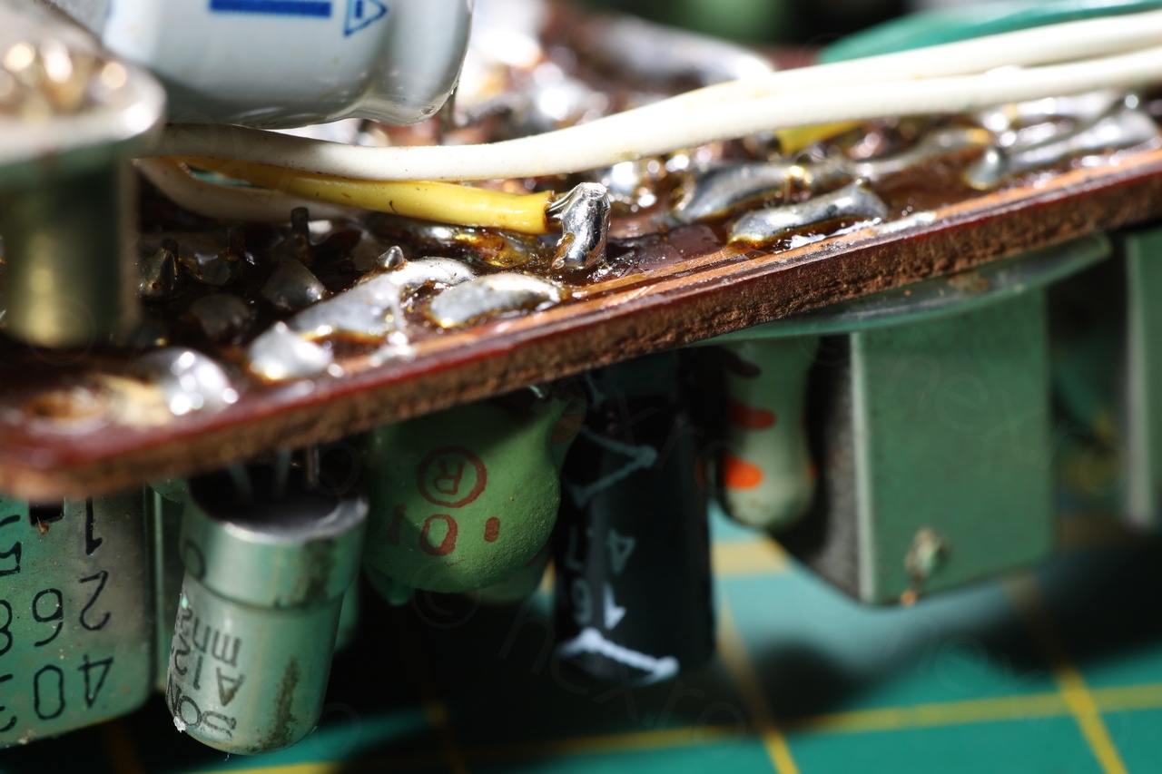
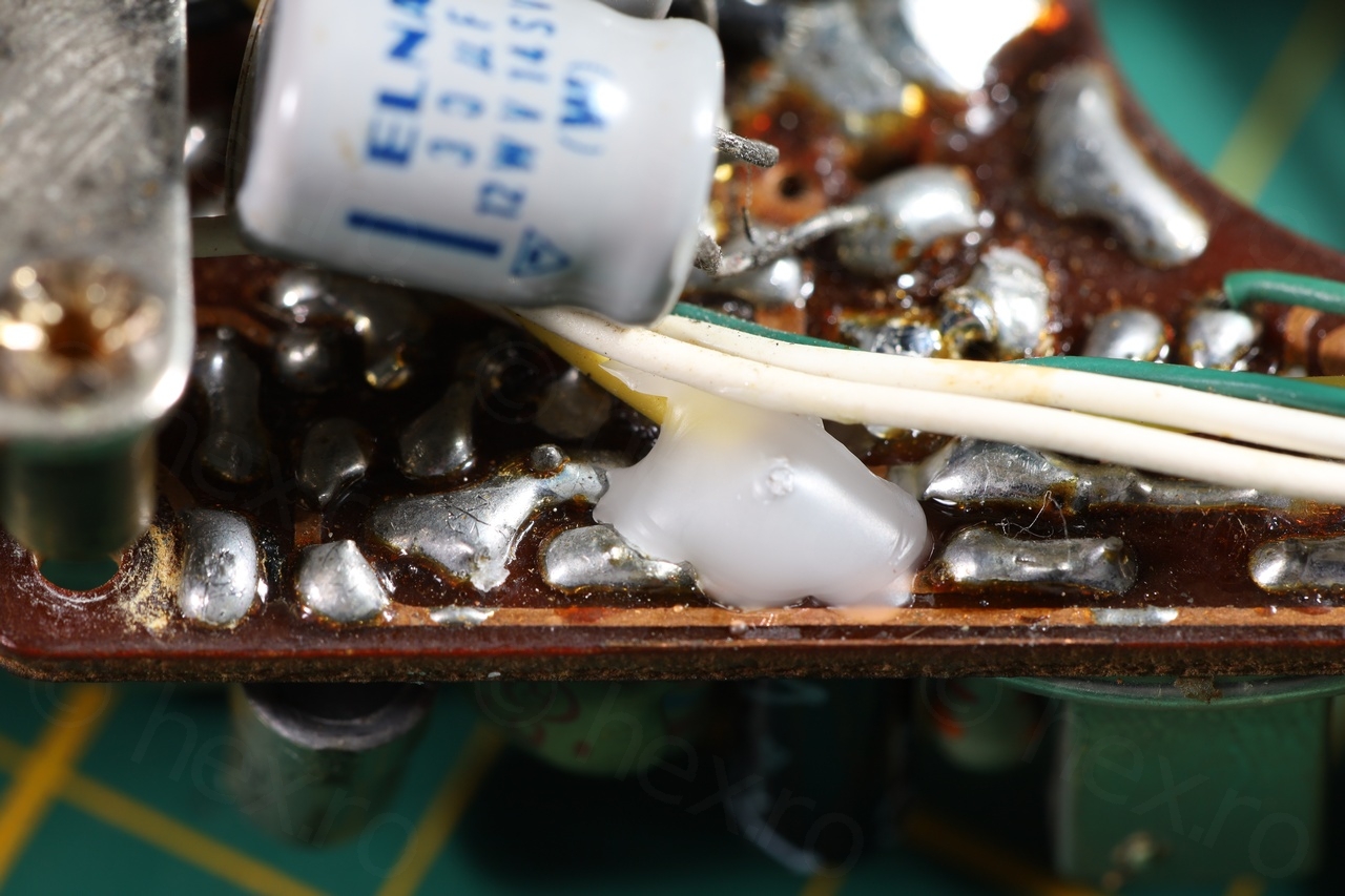
For the two capacitors on the back of the board, their legs were soldered on this huge pad where many other wires were going. Since it would be hard to re-solder everything back in place, I decided to just snip the former legs and solder new capacitors directly to the old legs.
Few more shots from the process of recapping it. I managed not to lift any other pads by using a vacuum suction pump to remove the excess solder followed by plenty wick and flux. This removes the remaining solder without putting pressure on the legs themselves or trying to wiggle the part and thus putting pressure on the pads. Cleaned with IPA before soldering the new capacitors:


Battery holder – 3D Printing
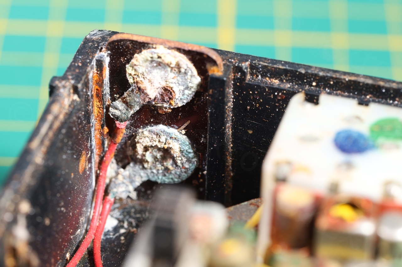
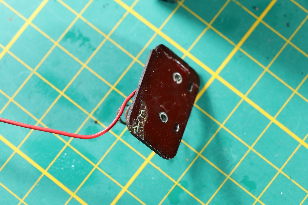
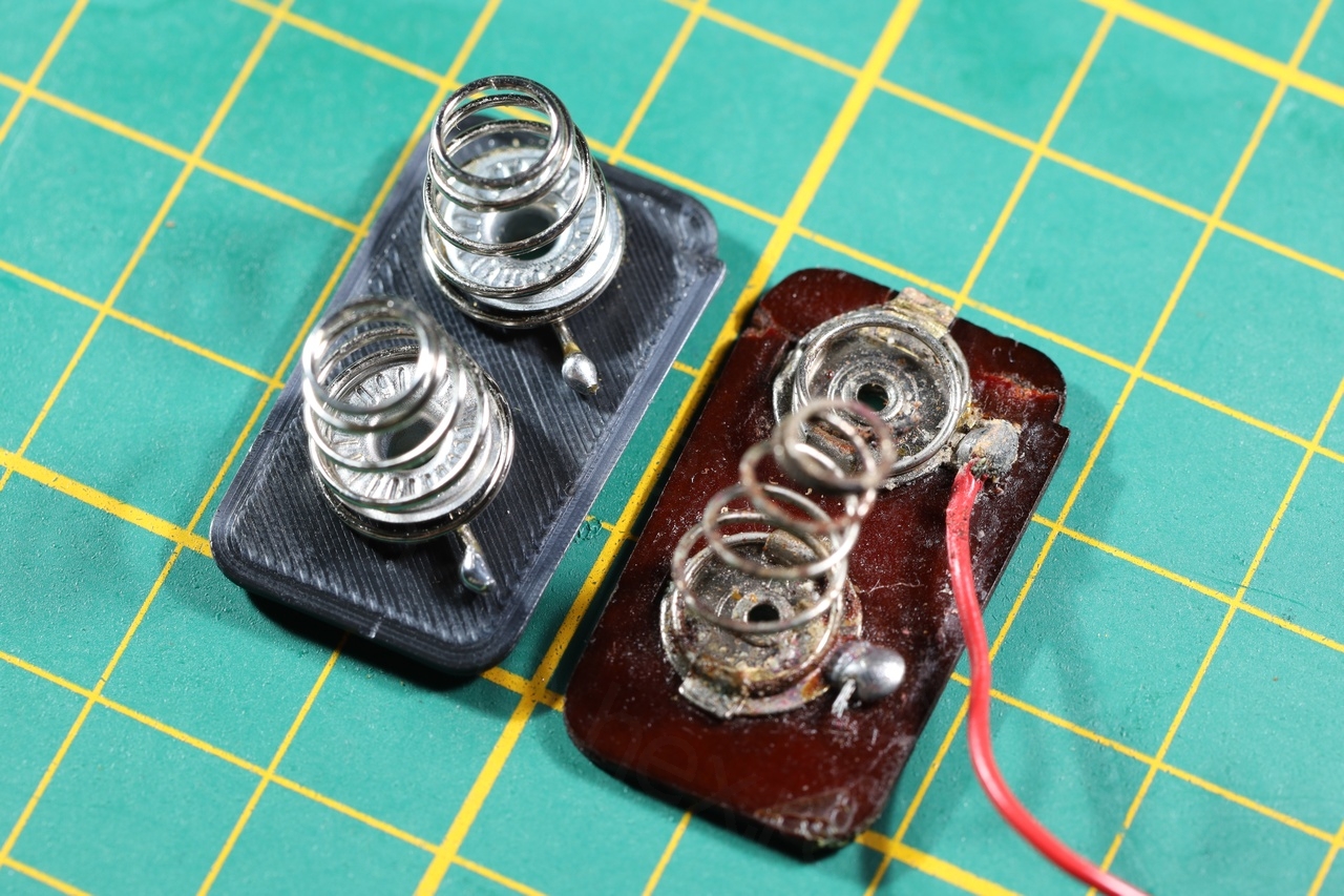
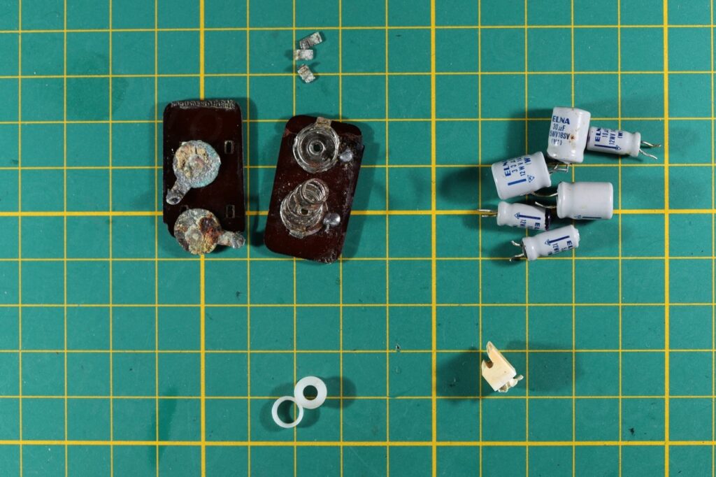
Not only the battery terminals were badly corroded, but the original support was also glued to the radio case. I broke one support (the negative one, with the springs) and manage to salvage the other, but I could not reuse them since I have no similar terminals nor way to manufacture them.

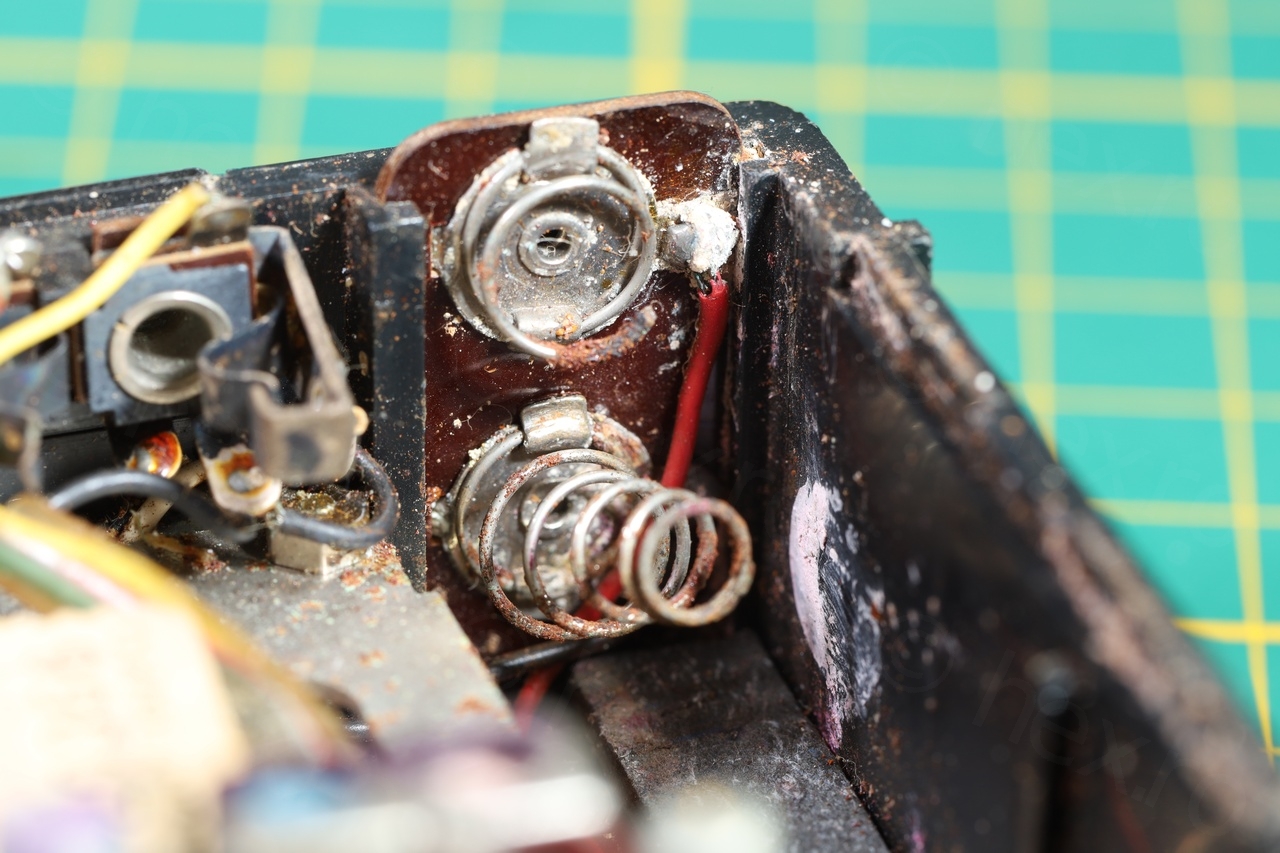
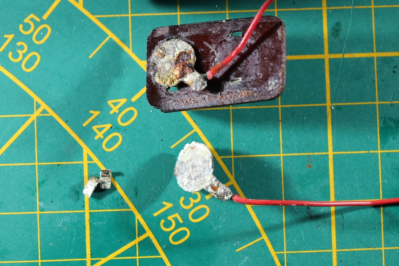
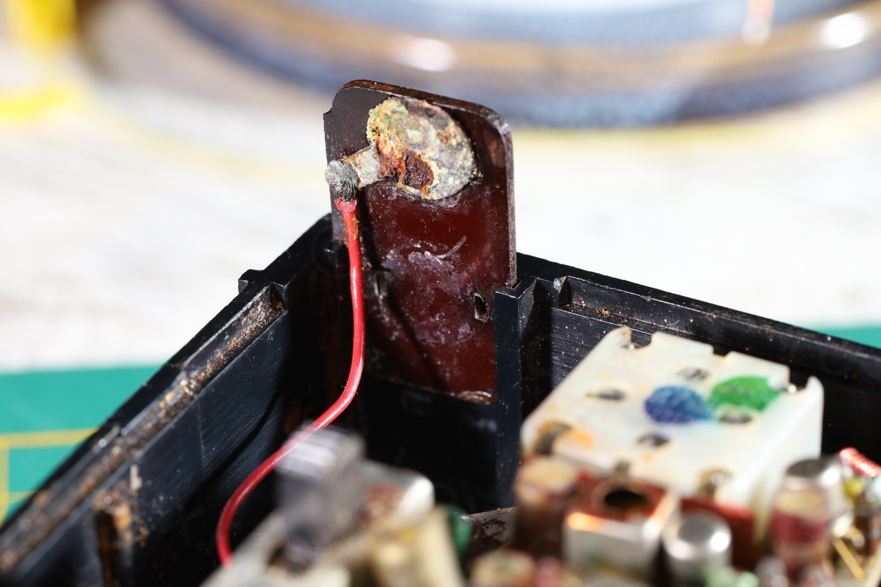
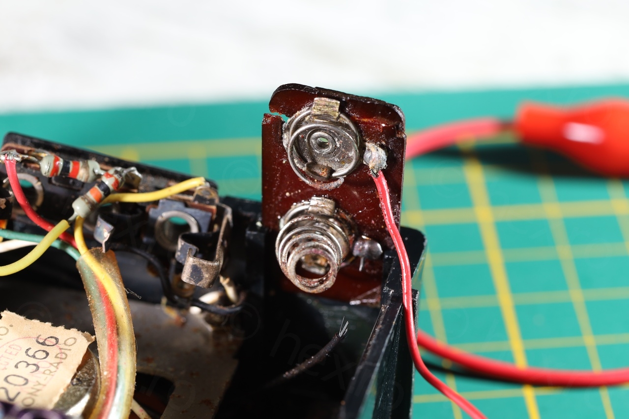
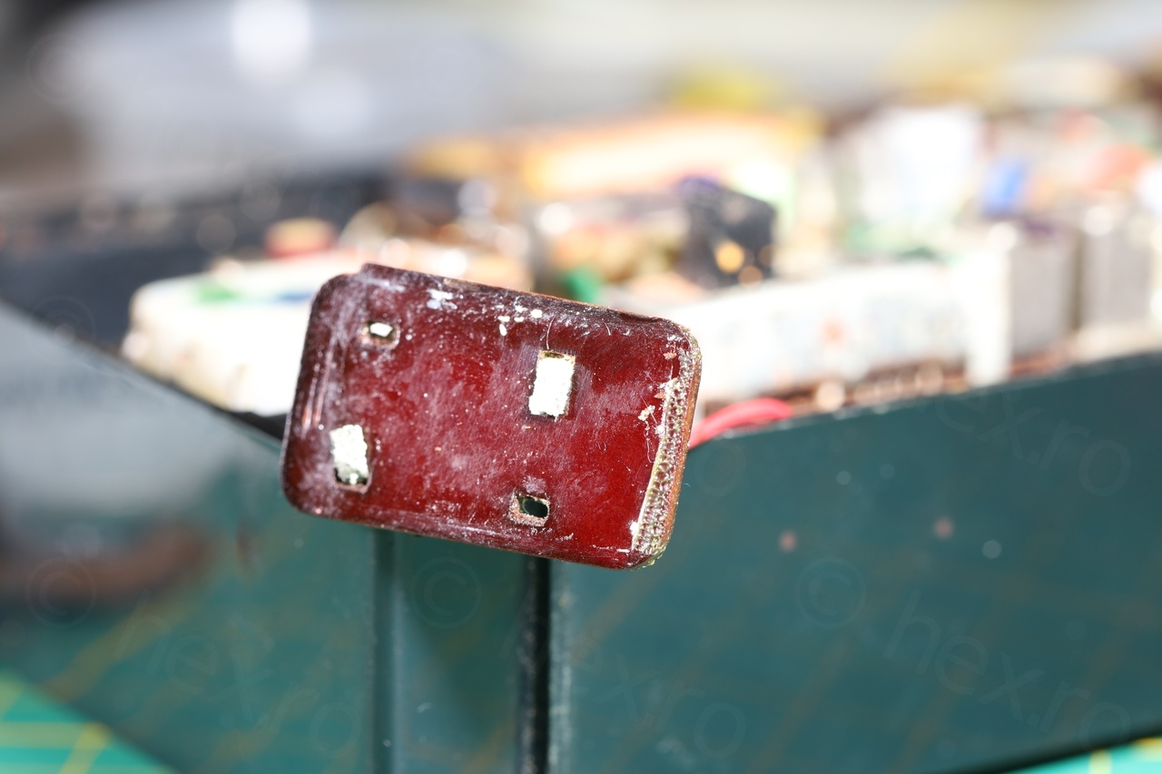

I had to use pliers and a lot of force to wiggle / extract them out, unaware that they were glued. Even if I would have salvaged these supports, it would have been difficult to adapt new springs or positive terminals to them.
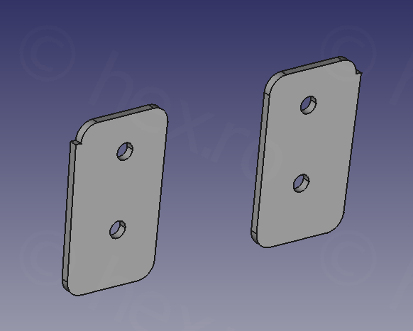
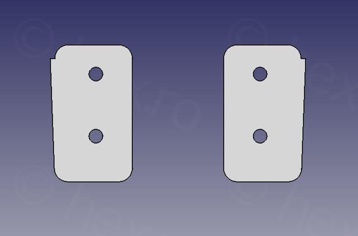
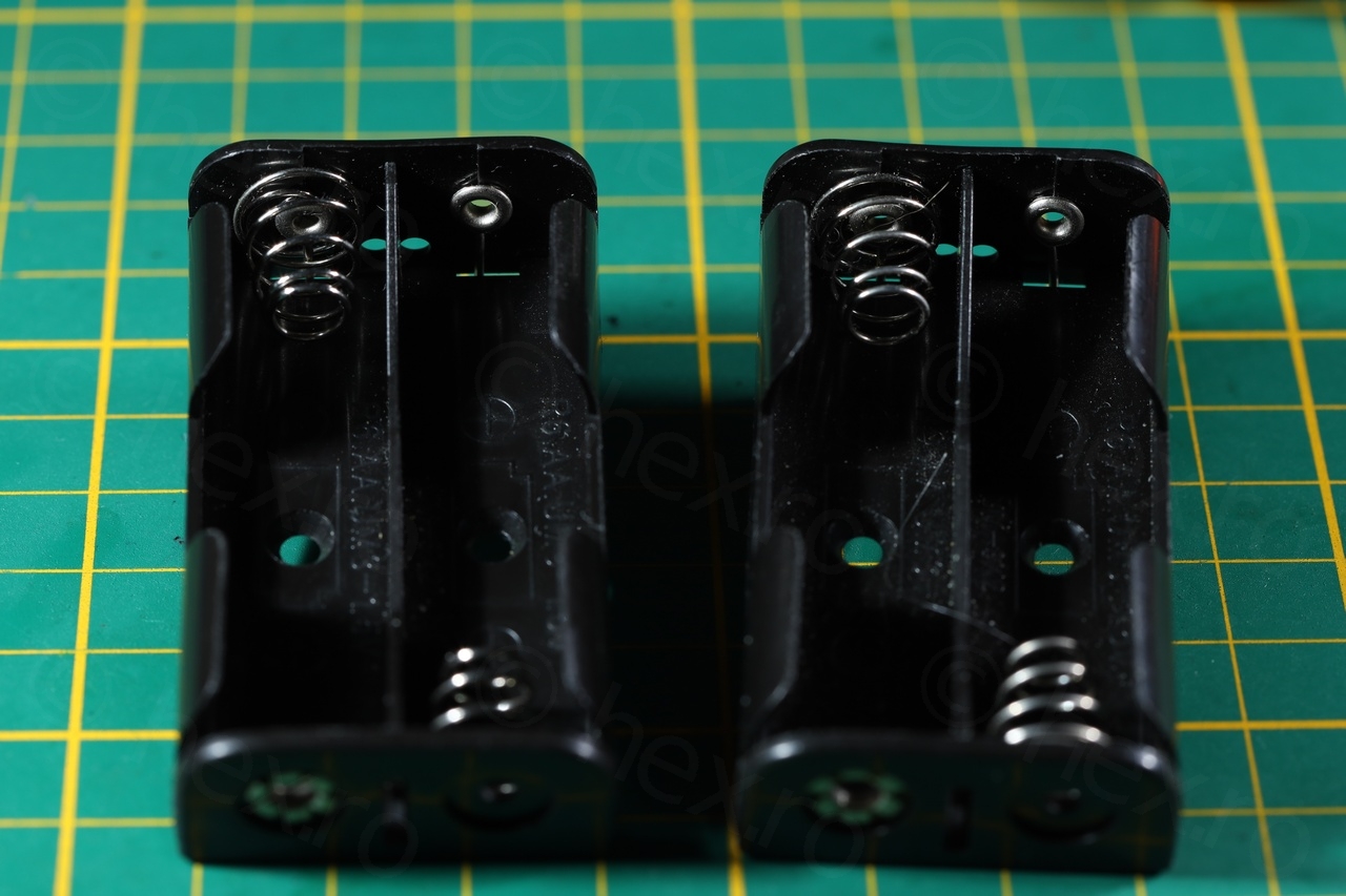
I decided to 3D print the supports terminals and use modern terminals taken from new battery holders. I know there are 2 rows x 3 AA batteries holders, but they do seem to cost a lot and the shipping time would be big.
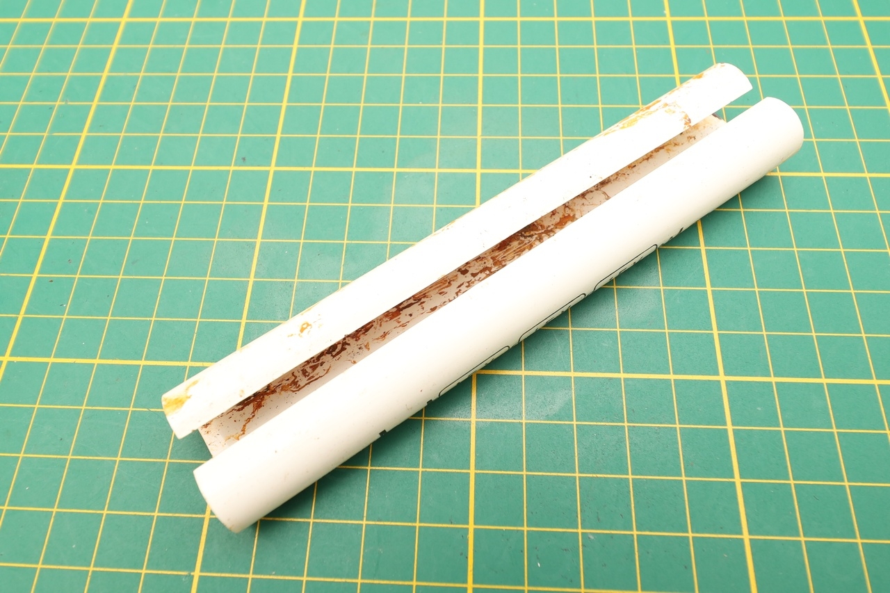
Since I was keen in reusing the battery tube or battery shaft (I have no clue how it is called), I proceeded to measure the holders and give it a go:

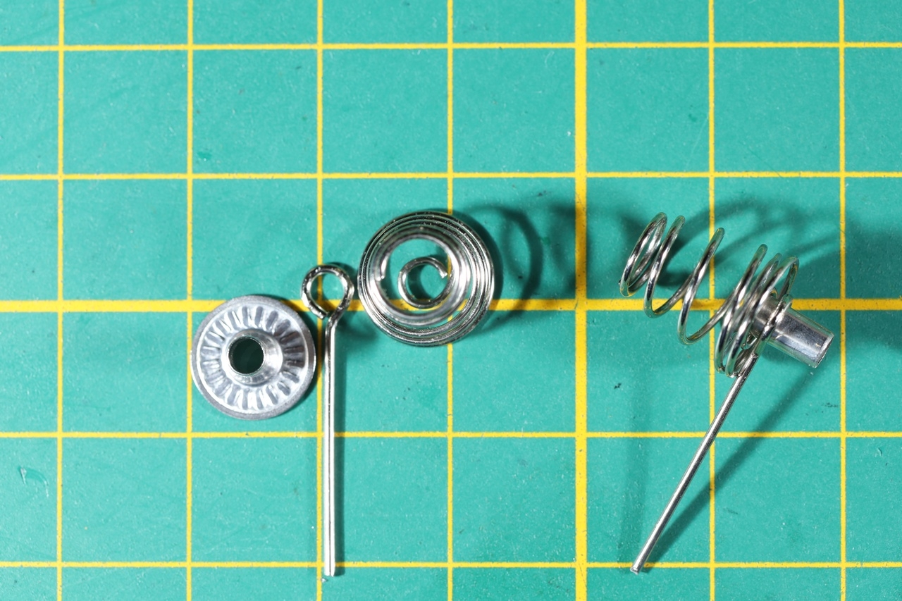
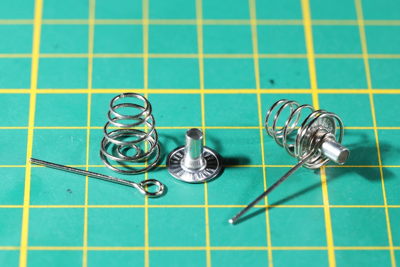
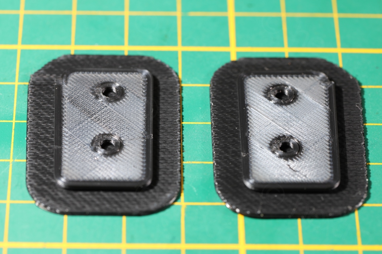


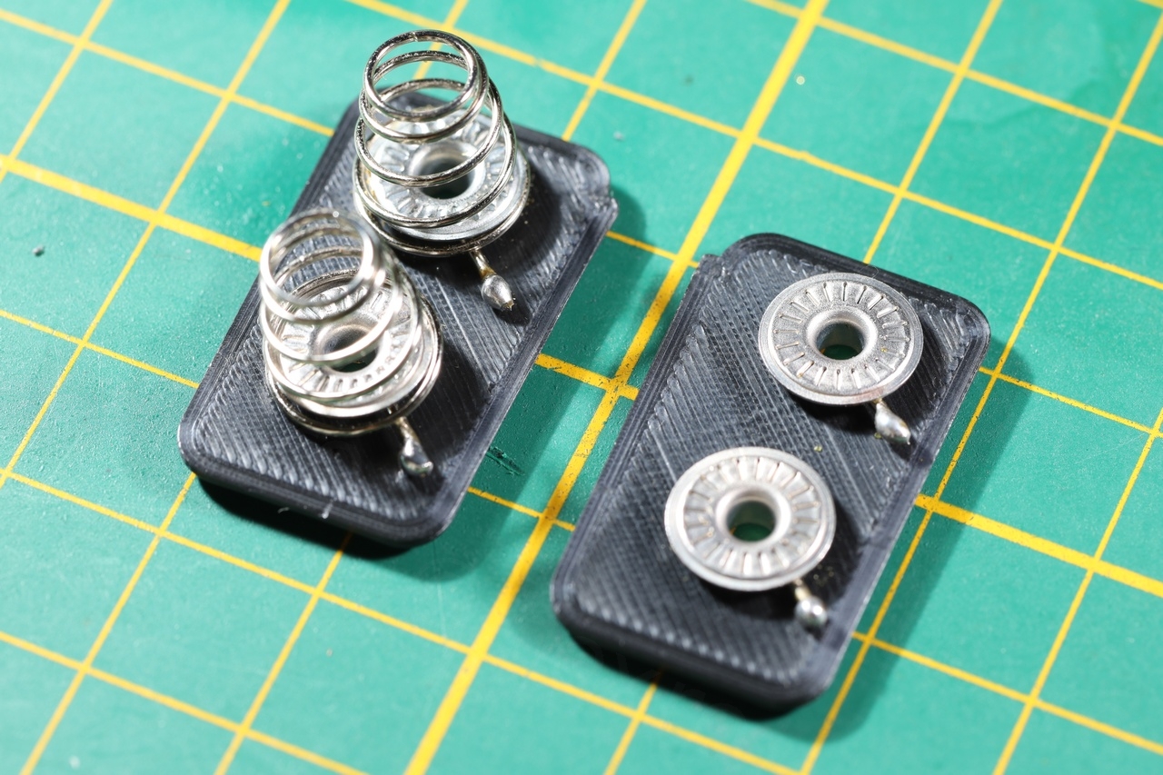
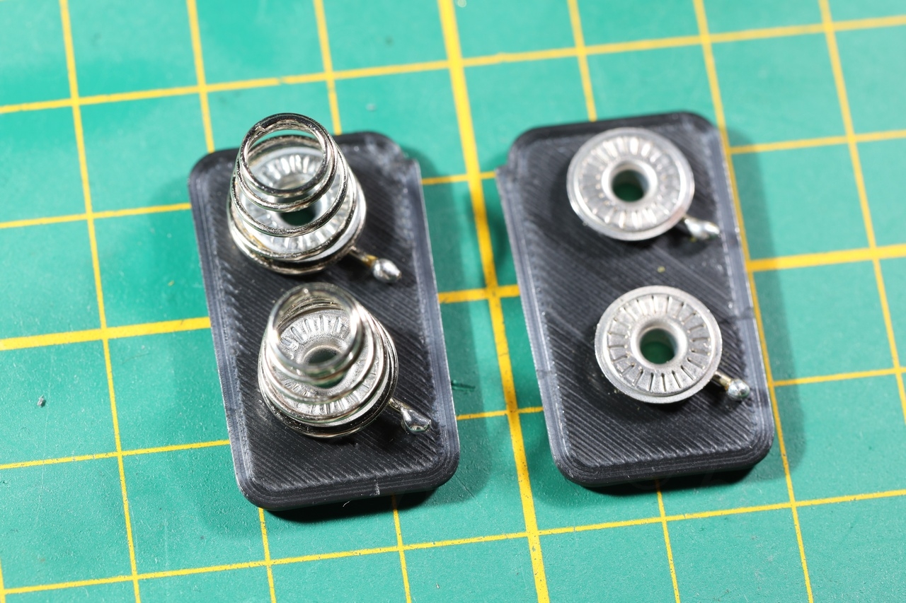
I had to use also some press fasteners to act like plates for the + terminal of the battery. Everything turned out perfectly:

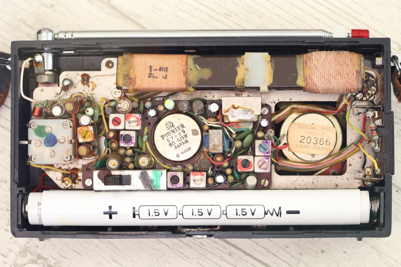
It almost looks like original 🙂
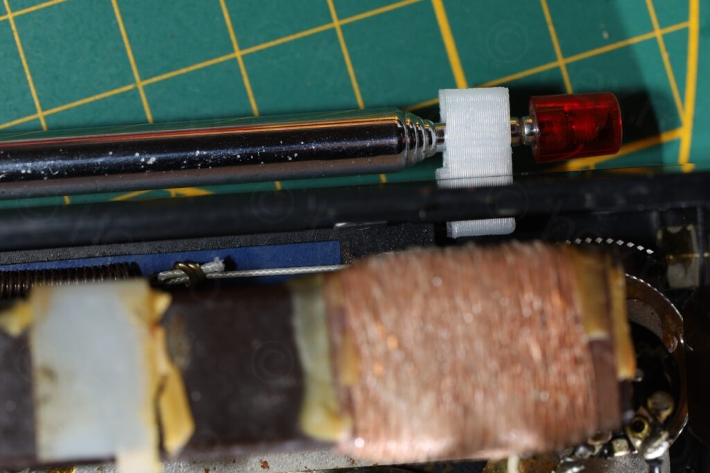
Tuning string rollers – 3D print
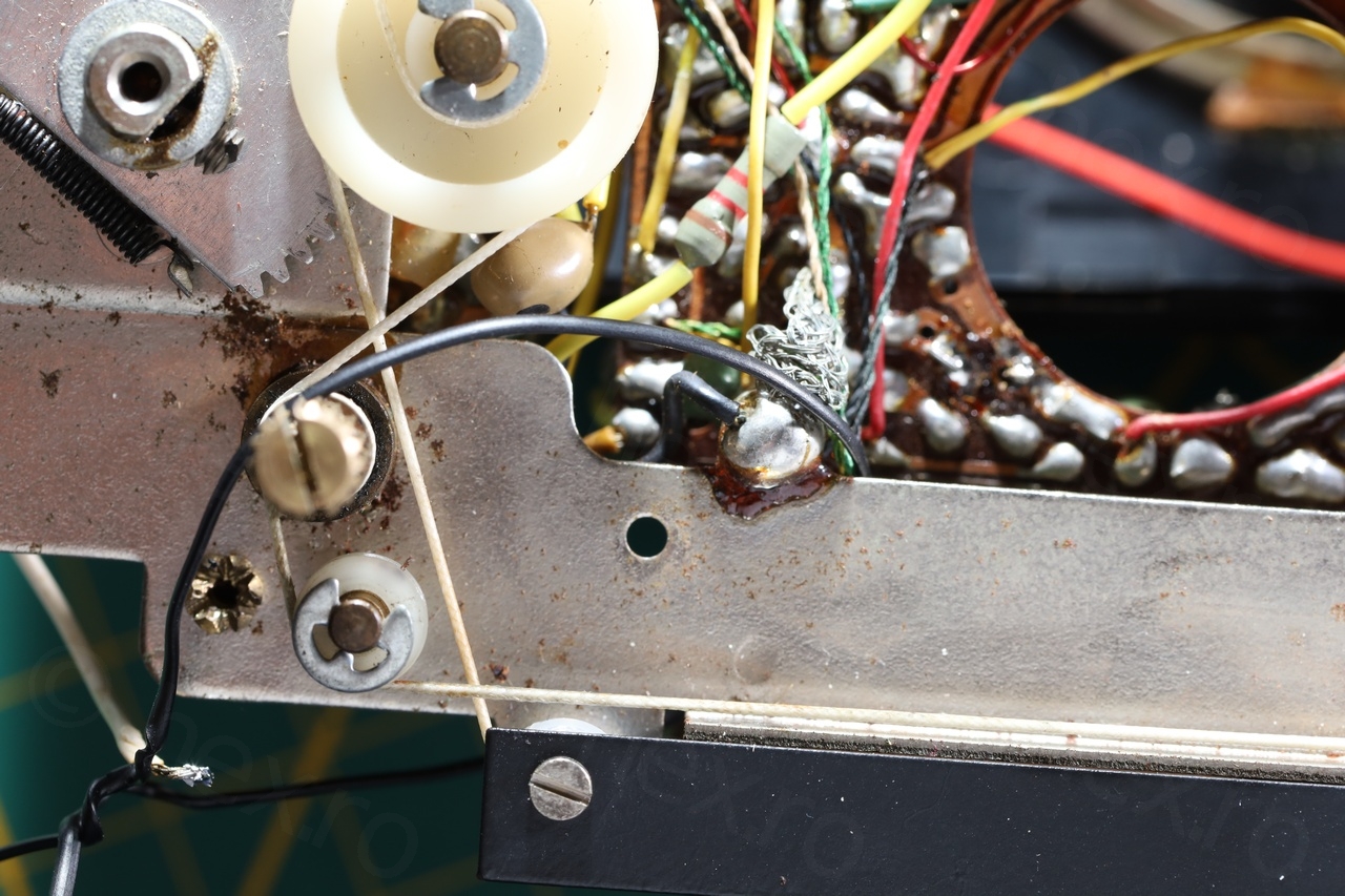
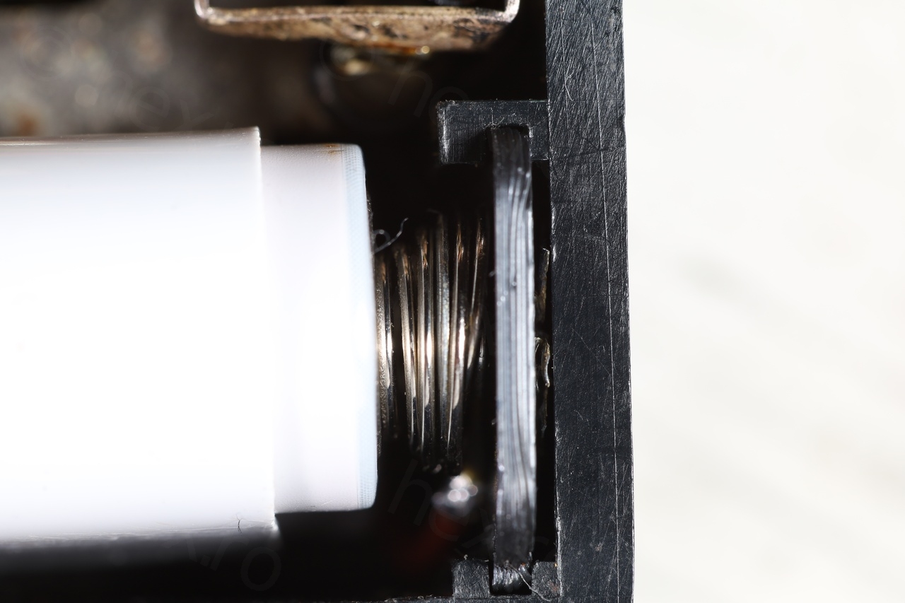
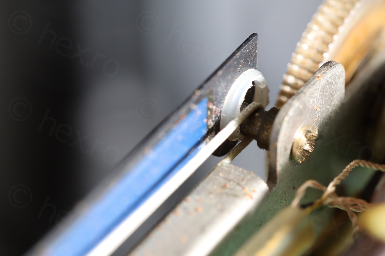
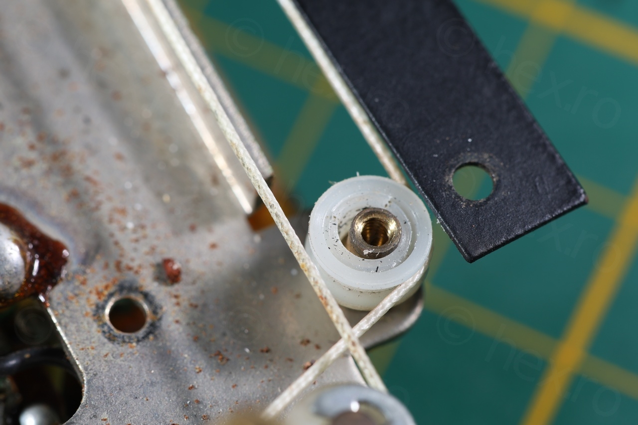
Another nasty surprise noticed when taking the radio apart is that the rollers / guides of the tuning strings were in a bad state. One was already cracked in half and the thread was rubbing on the metal, and the other one was already cracked:


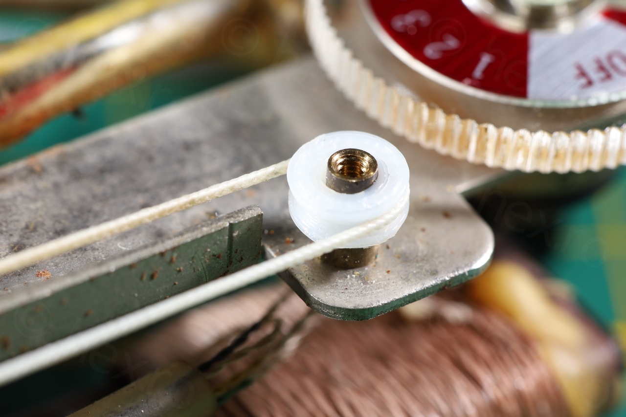
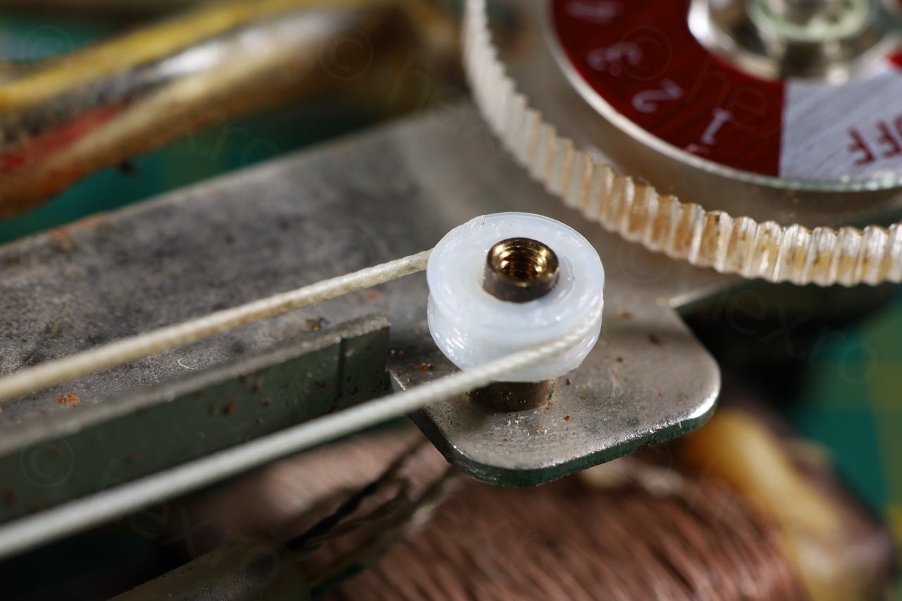
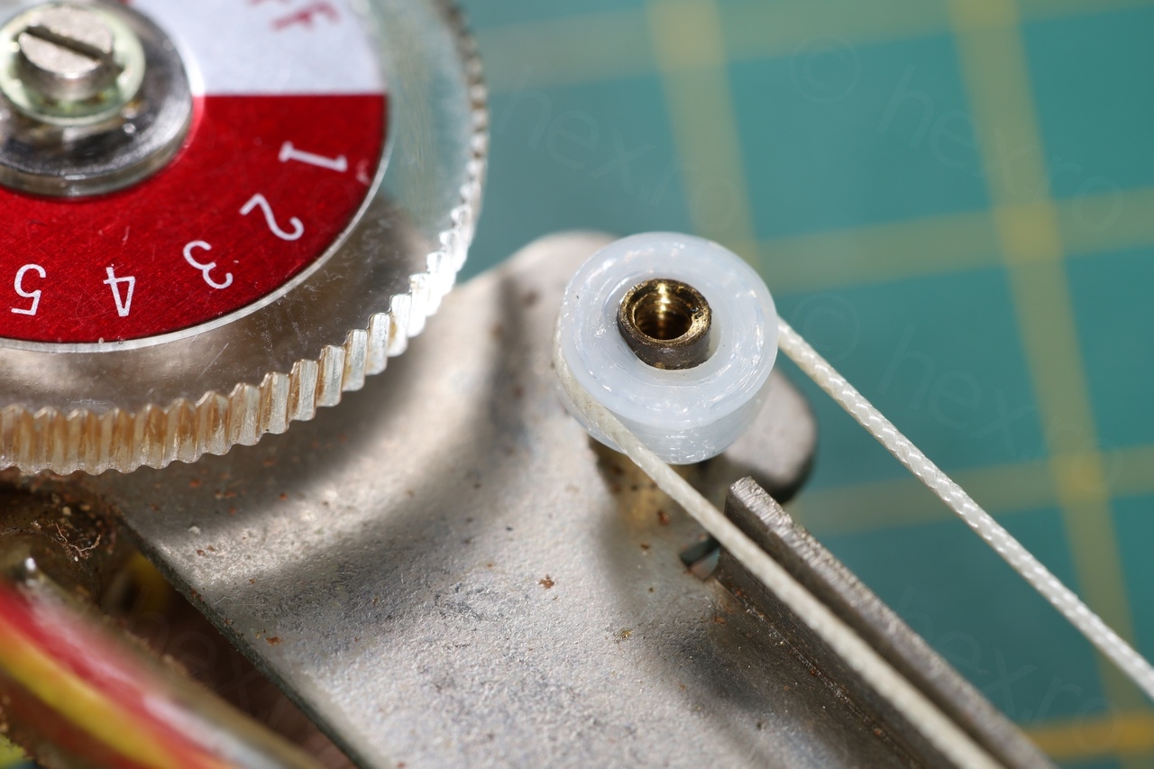
I designed these parts in FreeCAD – parametric design has advantages when prototyping, as one parameter change and the constraints take care of the others. However, when the 3D printer needs to move up one layer or change direction – the plastic is a little squished, meaning, the central hole of the roller is not perfectly smooth. I did file it with a fine file, but still there is a bit of wiggle. I added also some sewing machine oil on the brass shaft, making sure not to touch the tuning thread itself:
The results look good – there is still a bit of wiggle but at least now the thread is guided properly and doesn’t rub on metallic parts. Not sure how long the rollers last – the tension is very strong, but should be cheap to print a replacement.
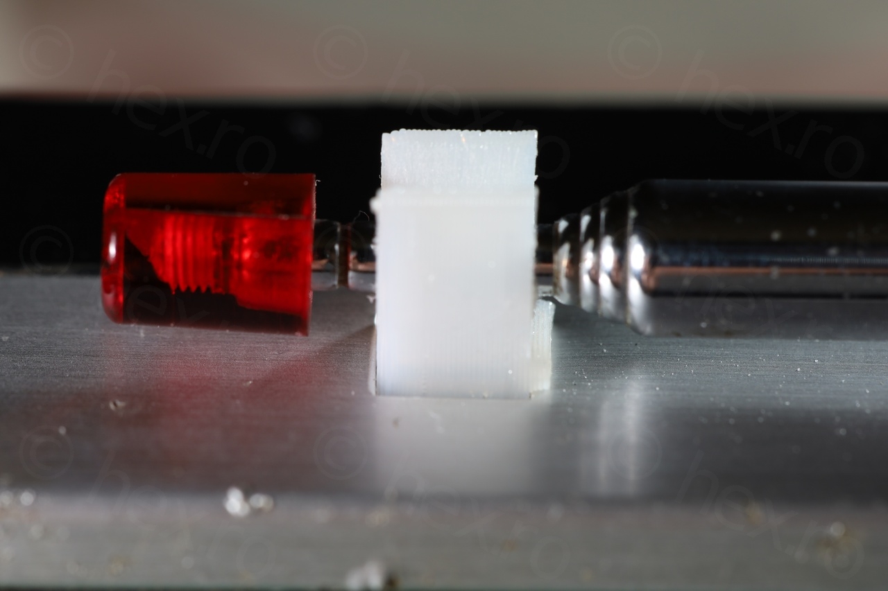
Antenna holder – 3D print
Another problem was the antenna holder, which was cracked:
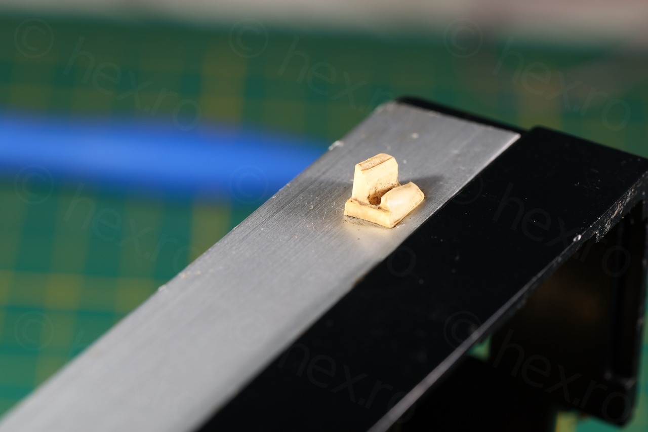
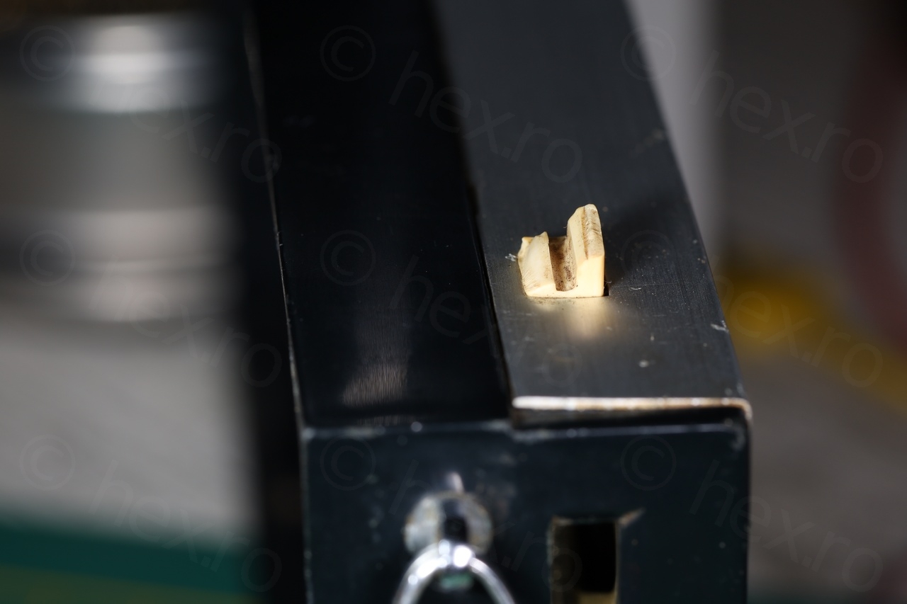
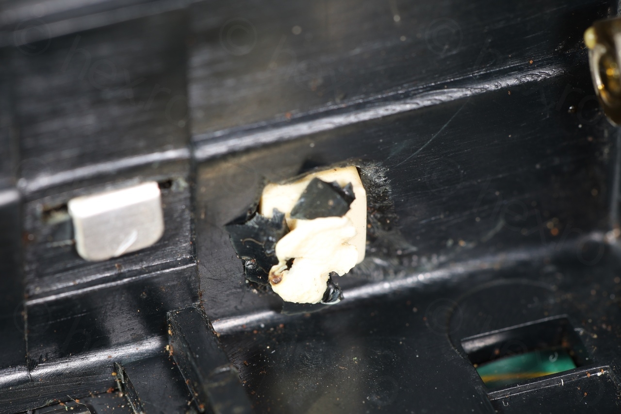
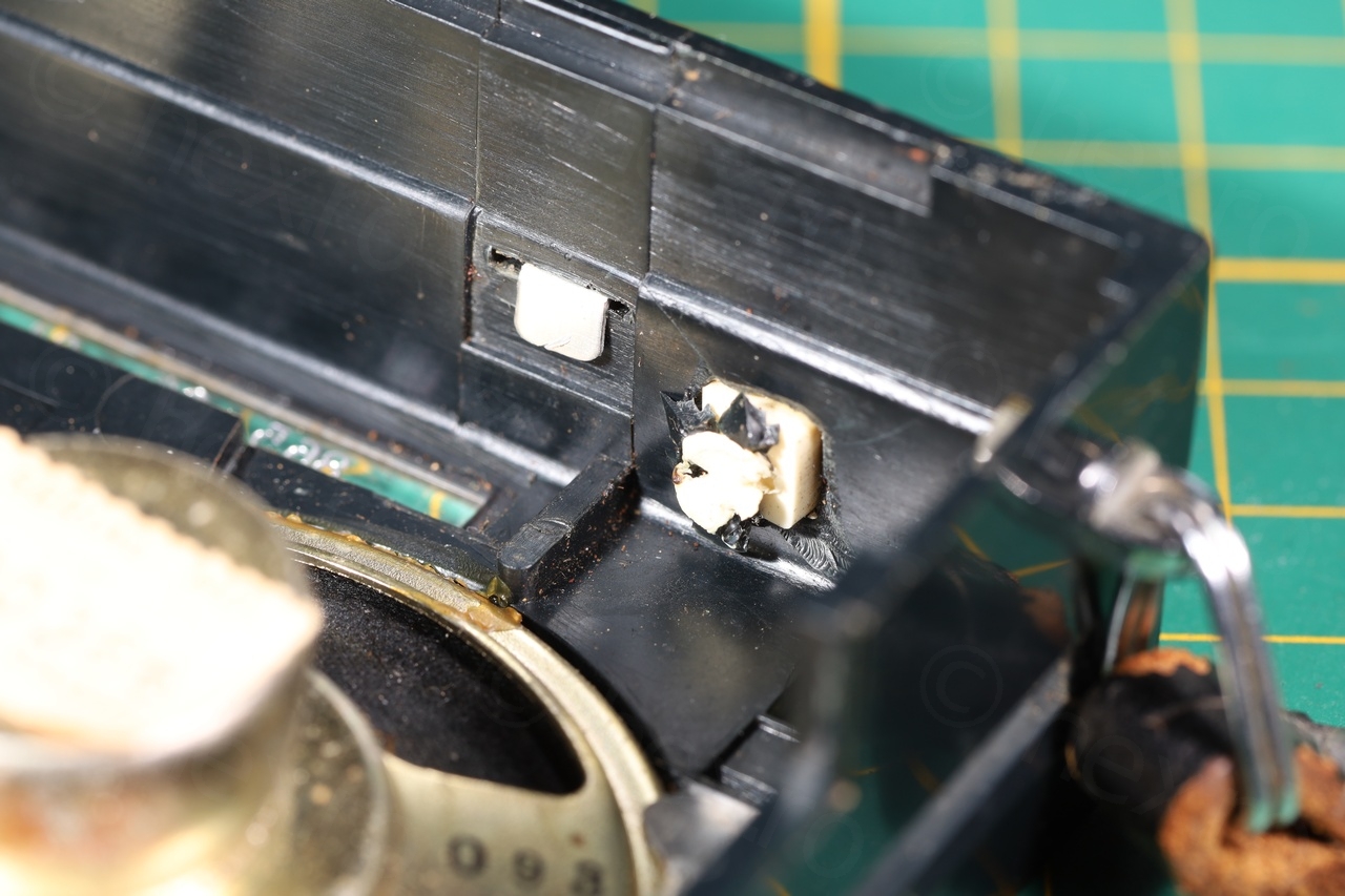
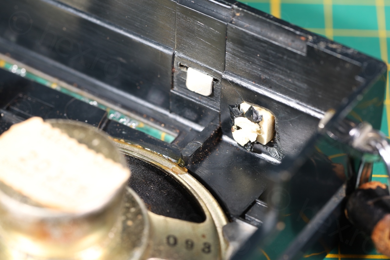
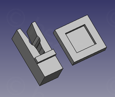
I wanted to 3D print a replacement but I could not find good enough photos online to show the details of the holder. This does seem a rare radio … However, I was able to locate some photos and get an idea on the original holder was supposed to be like, thus, more time spent in FreeCAD.
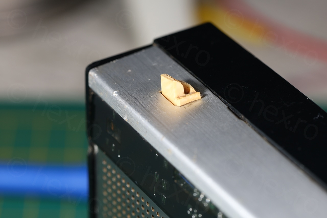
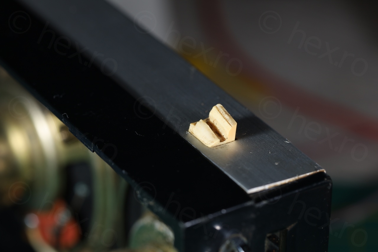
This needed a lot of trials to get it right (6 prints). Initially I figured I would superglue the base to the holder itself, but eventually I decided just to make it a square with a hole inside – easier to press-fit:

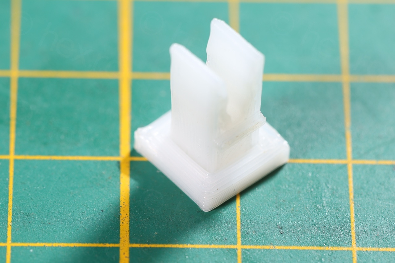
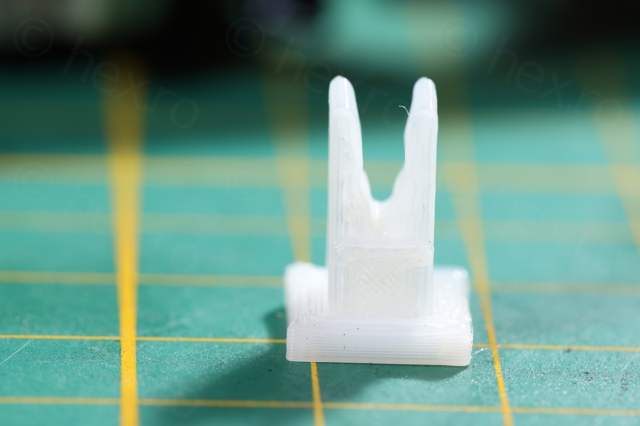
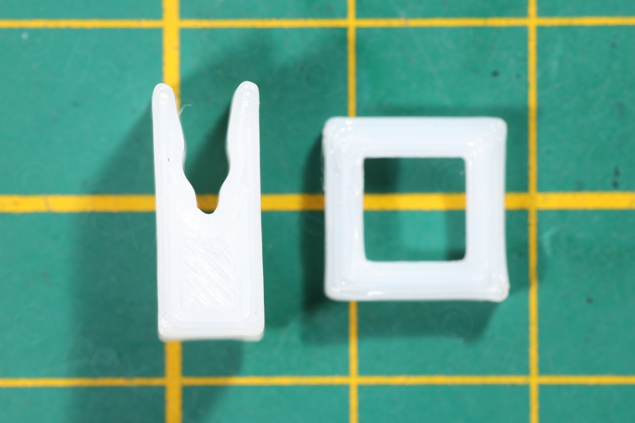

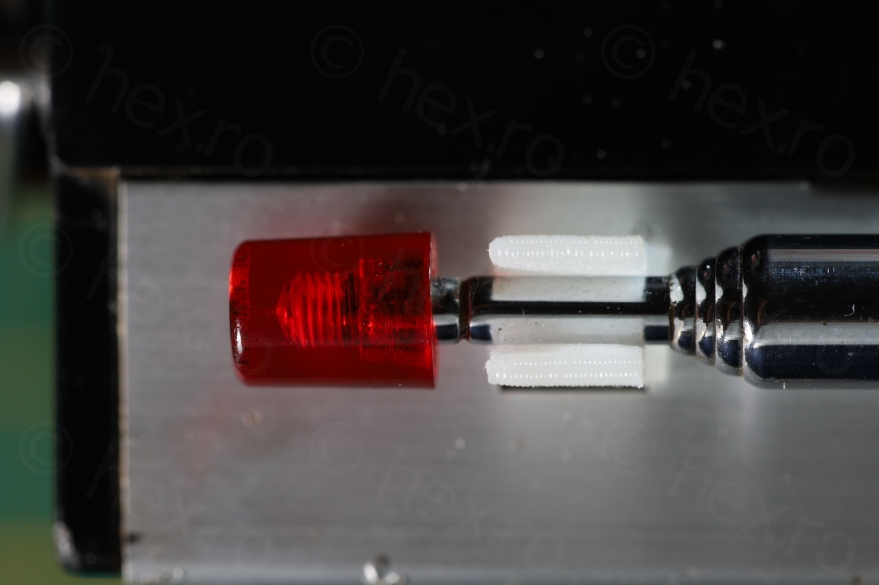
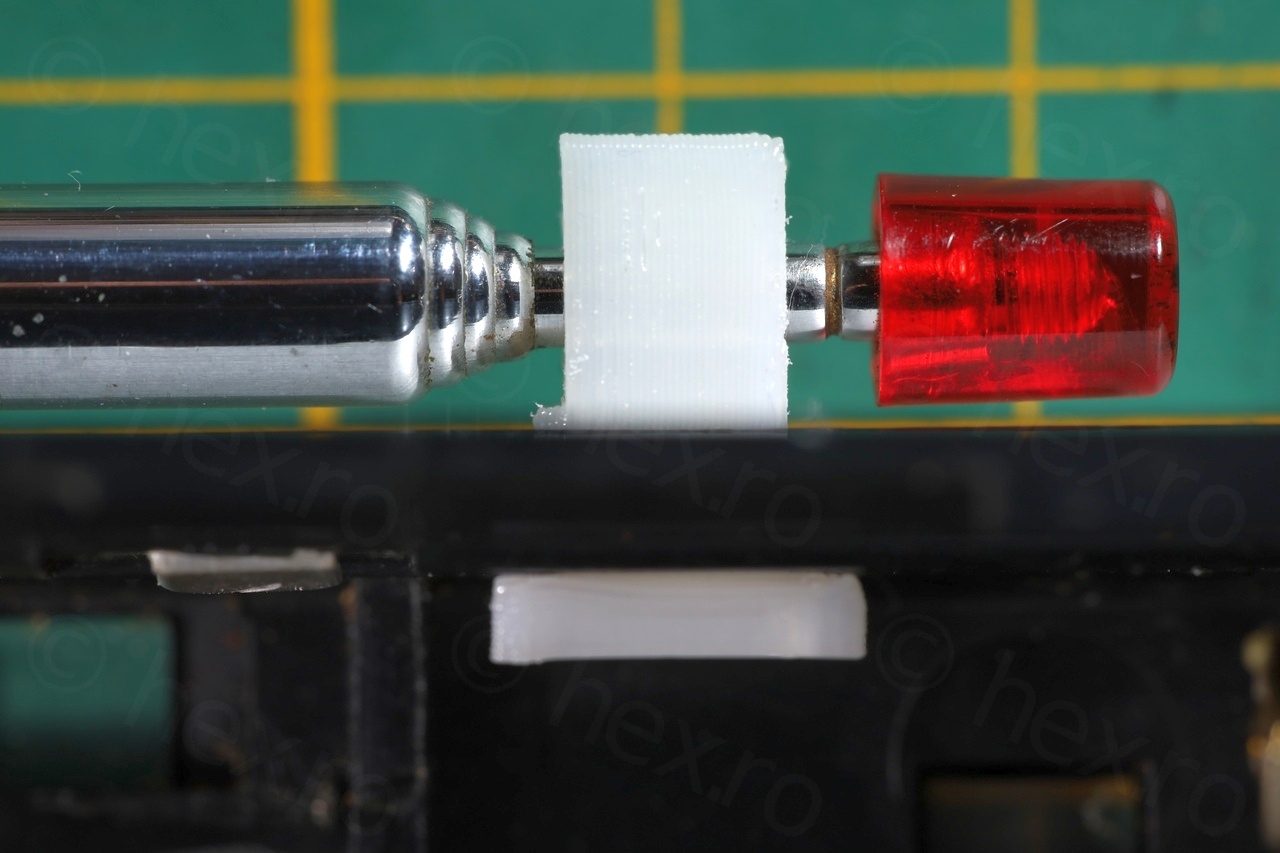

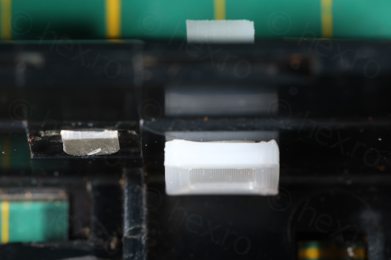
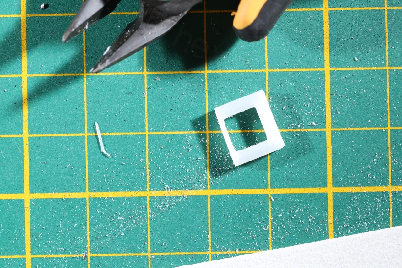
I did not glue it to the case of the radio, but I kept the original lip design (which should have prevented it from sinking down) and I just super-glued the square support to the holder. One issue that I encountered was that once the circuit board is inside, the square base of of the antenna holder was pushing against the board. I thus filed it a bit just enough get some clearance:
Other observations
Germanium transistors thermal runaway
When I first took the radio apart, I spotted that two of the transistors were very corroded. During diagnosis I realized they are the final output transistors (model 2SD65, Germanium type) and not only that, but they suffered from thermal runaway – the current draw was increasing to 150mA and as they becomed hotter and hotter. Current was capped to 150mA, the circuit provides enough protection to limit this effect.
This effect did not manifest once I changed the open C233 capacitor that was in series with the volume potentiometer. I did keep the radio running for hours without any problems.
An additional problem that I have left unfixed is the crackling while tuning. This may be related to the tuning capacitor itself, but I decided not to open it up – since it doesn’t affect the normal operation for now and seems to be a very tedious process to disassemble and reassemble it.
In summary, these parts were replaced:
A small demo with the radio working:
and photos with all cleaned up and put back together:
This was a tedious albeit fulfilling repair which was made possible by 3D printing the spare parts needed to have radio as close as possible to its original aspect and function.
Salvador Galan Ocaña
Hola, felicitaciones por esa magnifica y minuciosa restauración de la que he aprendedido mucho. Solo decirle que la mancha del portapilas en el exterior en forma de cinturón, es debido a restos de cola de contacto que en origen soportaban una cinta de tela gris para la extración fácil de las pilas. Adjunto enlace a la foto. ENHORABUENA por su restauración y saludos desde España.