


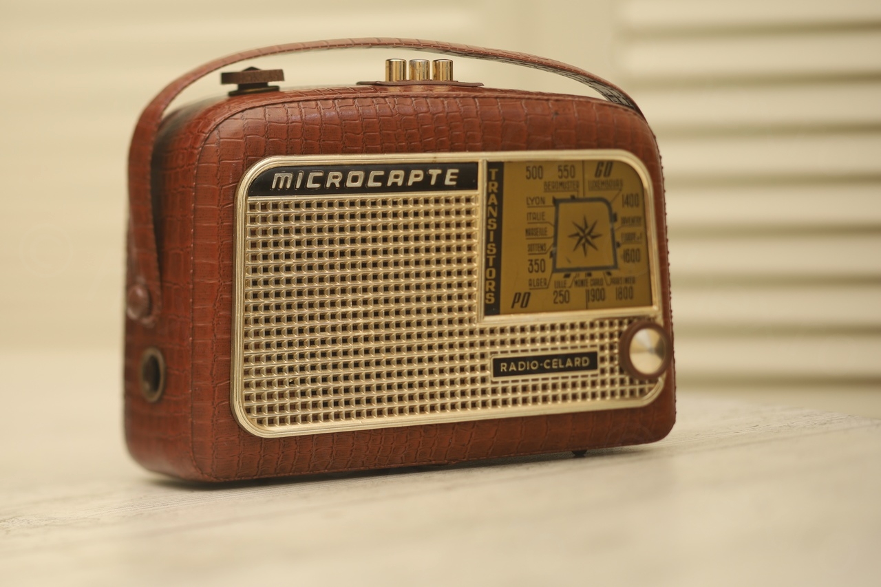
This radio drew my attention at the local flea-market. I negotiated with the seller not yet being fully convinced I want to have it, but it just looked too good for its age. A quick check online if schematics are available, followed by a good offer from the seller, I could not say no.
It ended up being a lengthily restoration, the radio was beautiful outside but rotten inside.
Table of Contents
- Exterior aspect
- Interior aspect
- Schematics inadvertences
- Replacing the corroded amplifier transistor (T6)
- Rebuilding the corroded lead of the driver transistor (T4)
- Diagnosing missing Collector voltage for final amplifiers
- Fixing a cut Litz wire
- 3D printing the cover of the interlock band switch
- Faulty On/Off switch of the Volume Potentiometer
- Rebuilding the Volume Potentiometer
- Faulty Electrolytic Capacitor
- Diagnosing faulty T3 (SFT107) transistor
- Diagnosing faulty T2 (SFT108) transistor (oscillator / mixer)
- Reattaching the front grill
- Fitting a new battery holder for AA batteries
- Unsolved issues
- Photos
- Testing the radio (video)
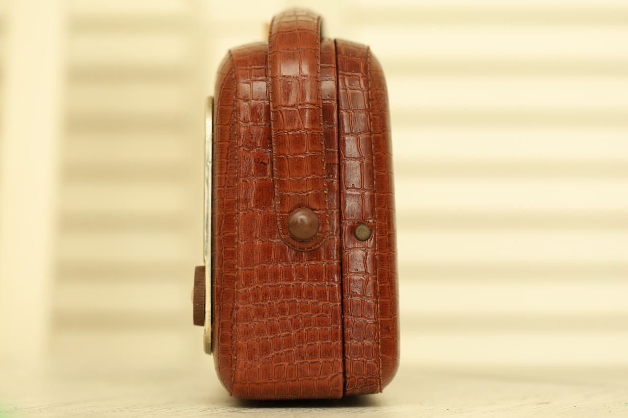
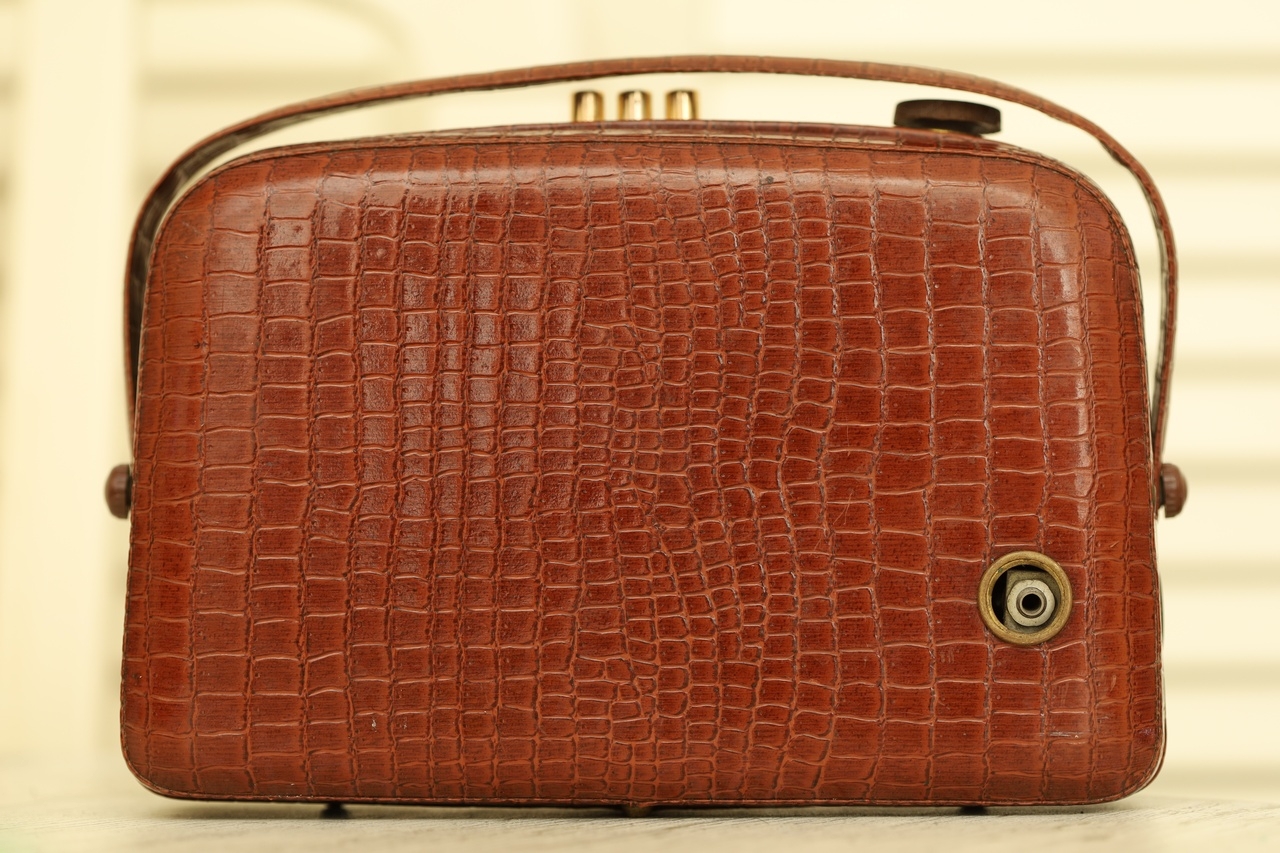
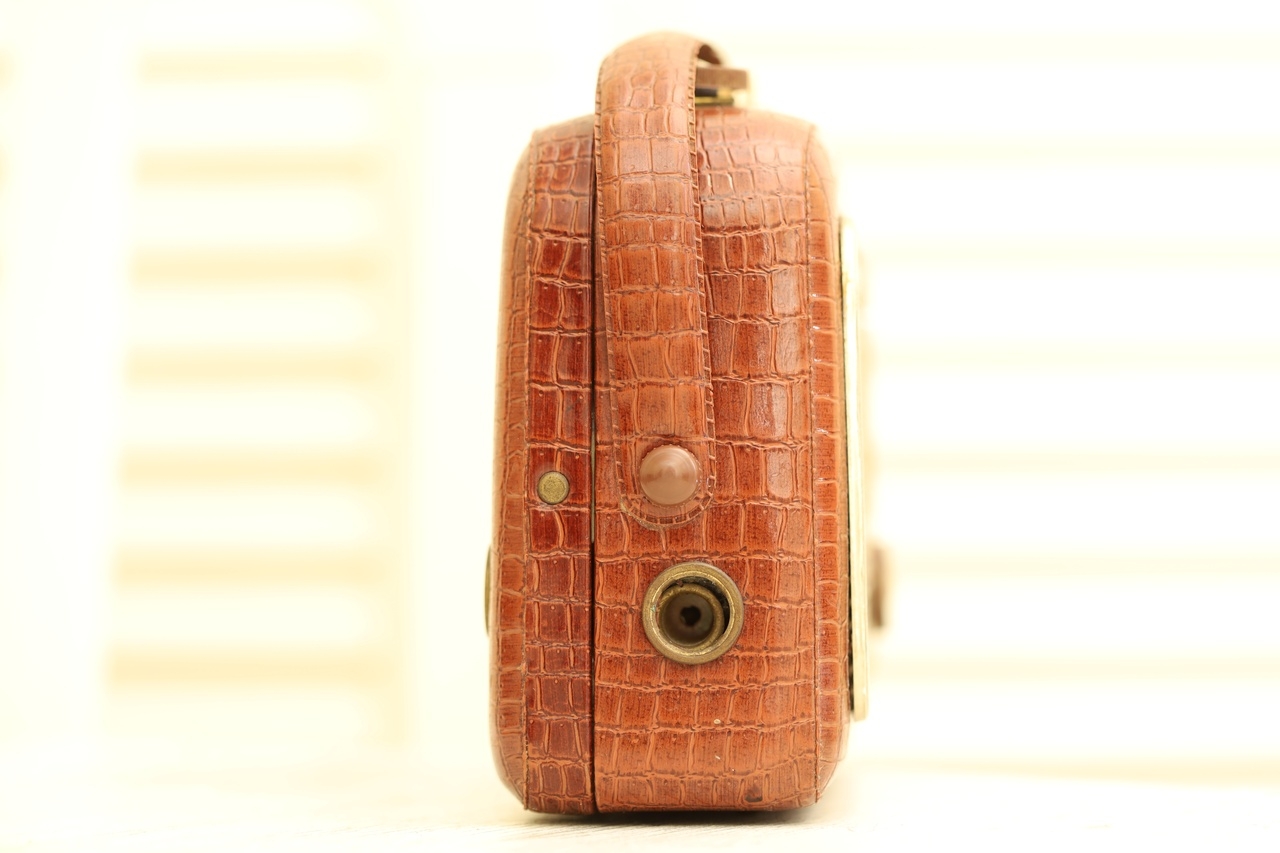
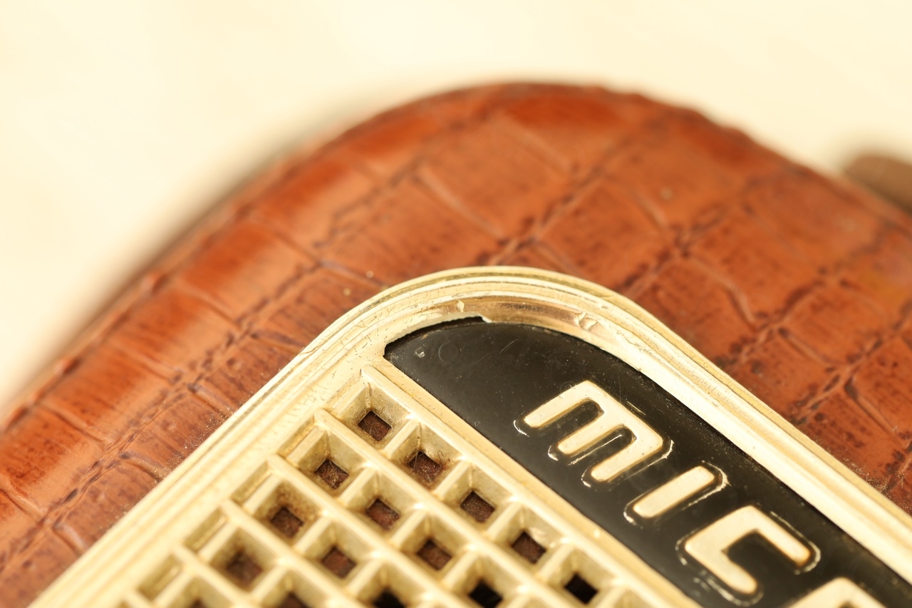
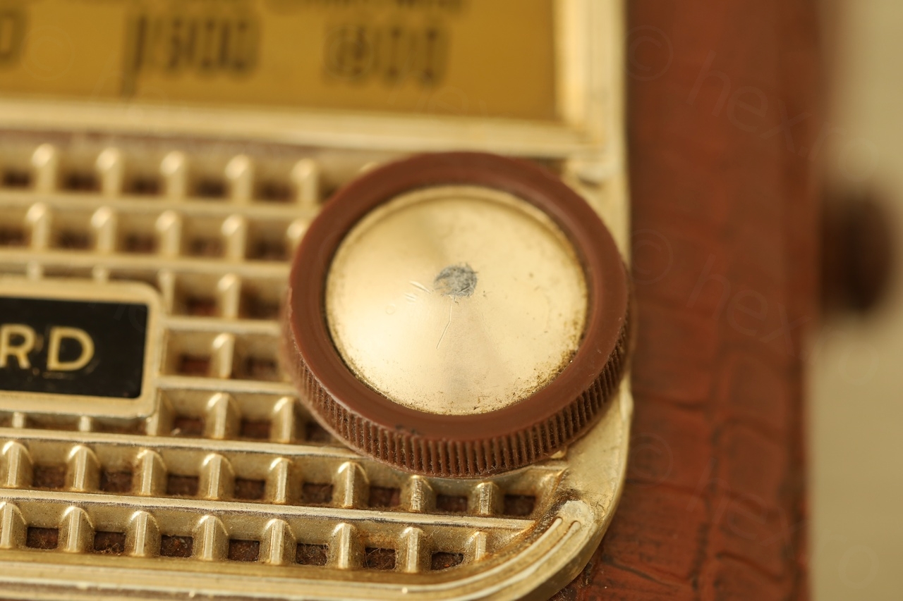
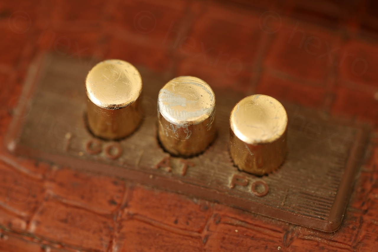
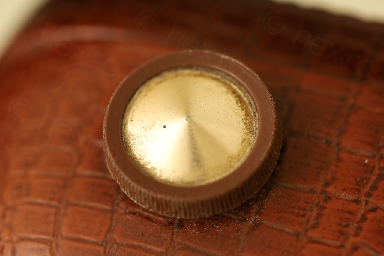
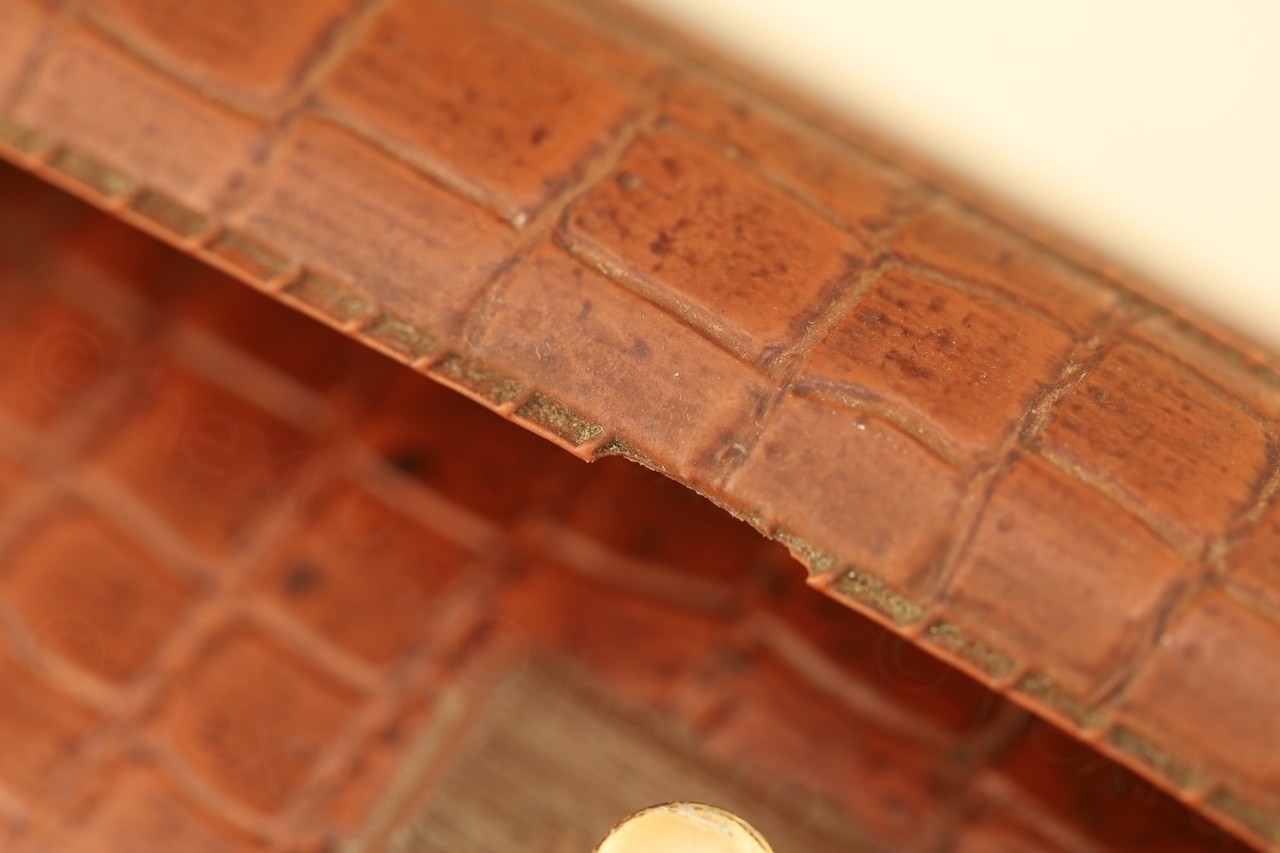
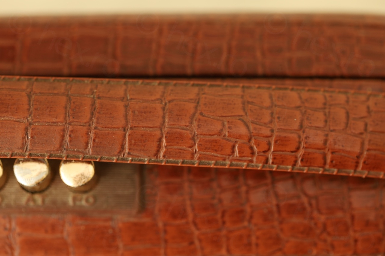
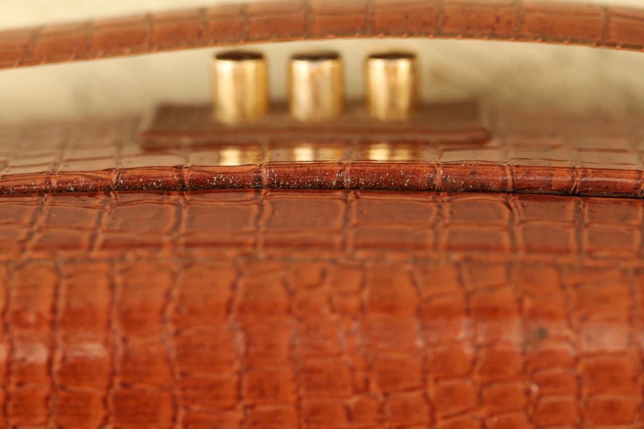
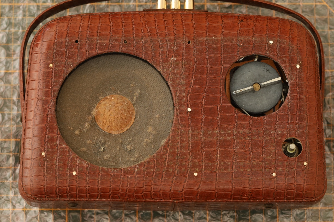
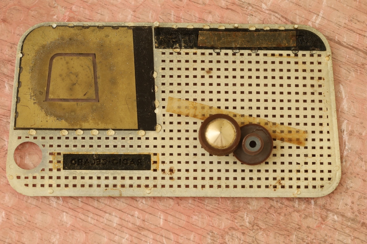
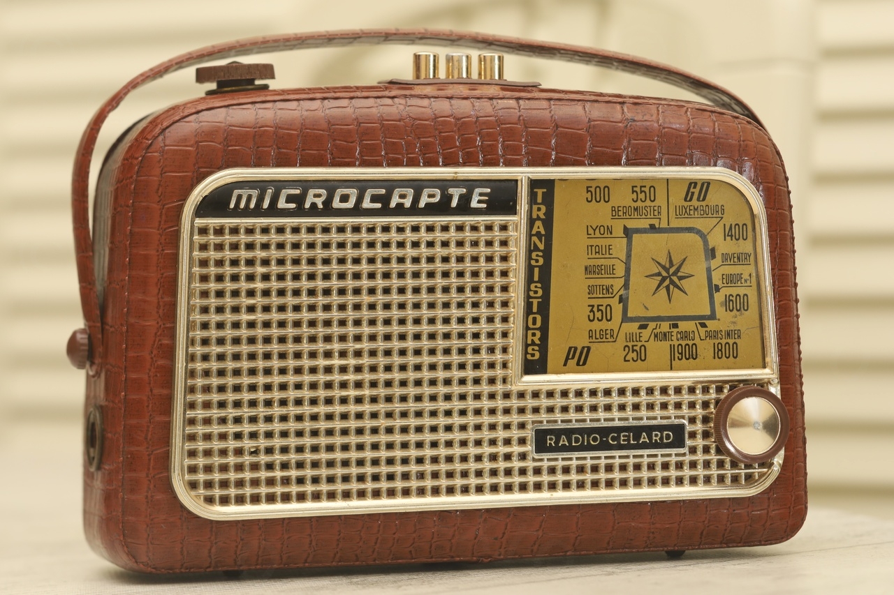
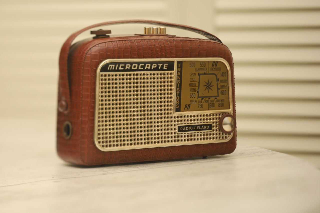
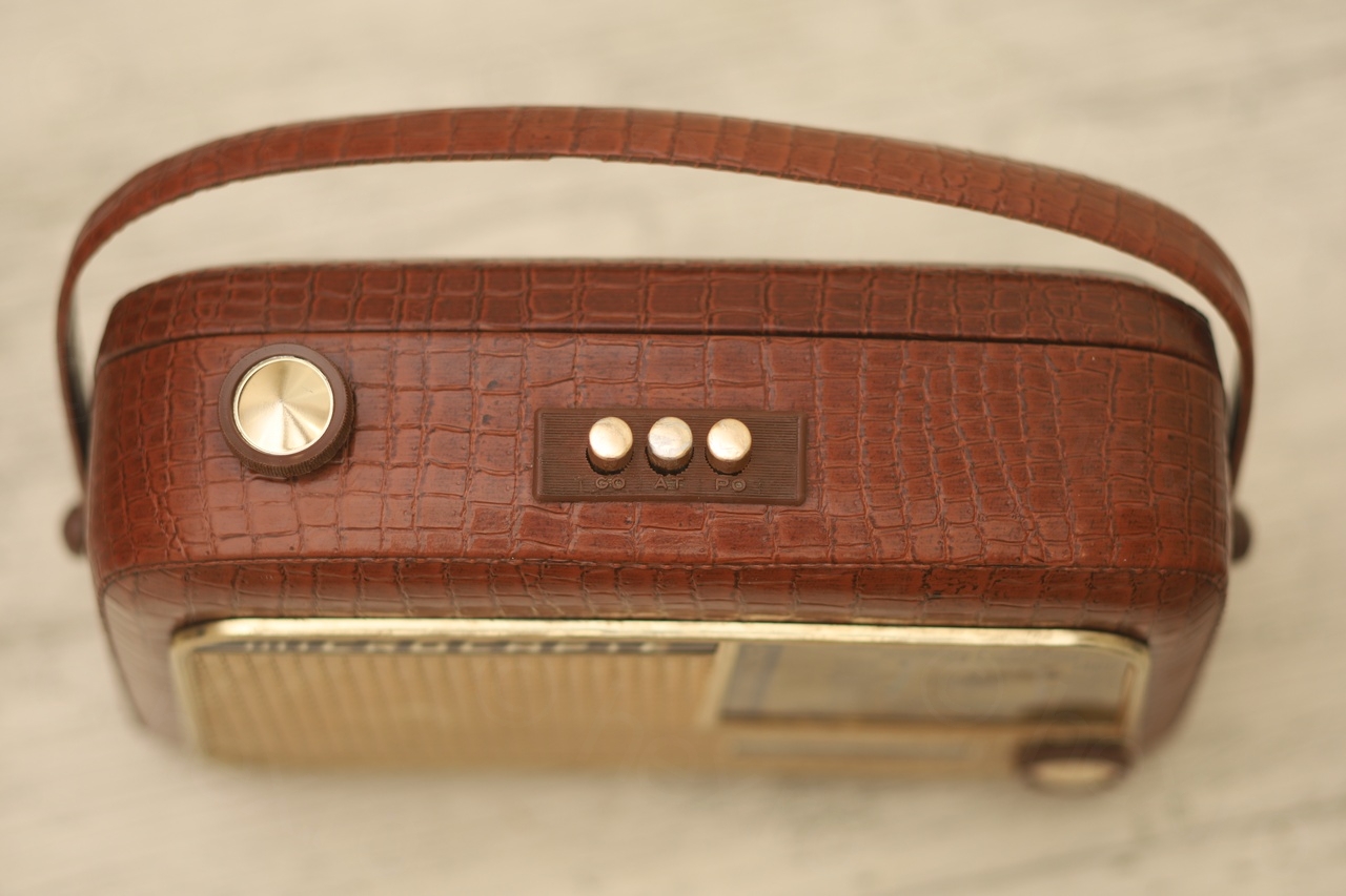
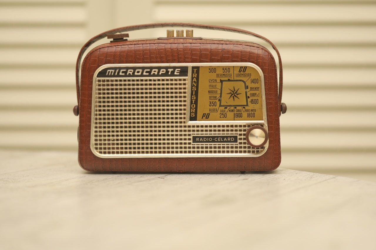
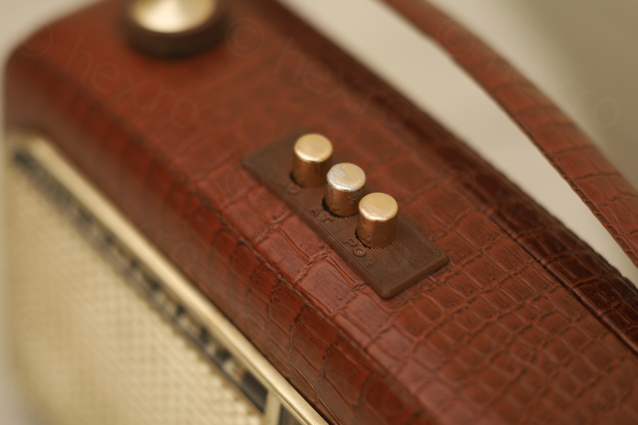
Exterior aspect
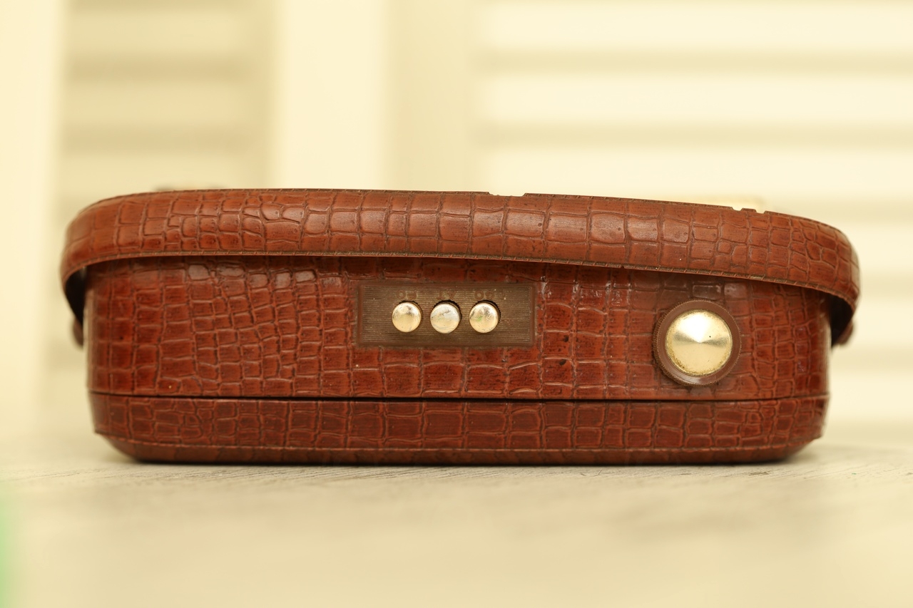
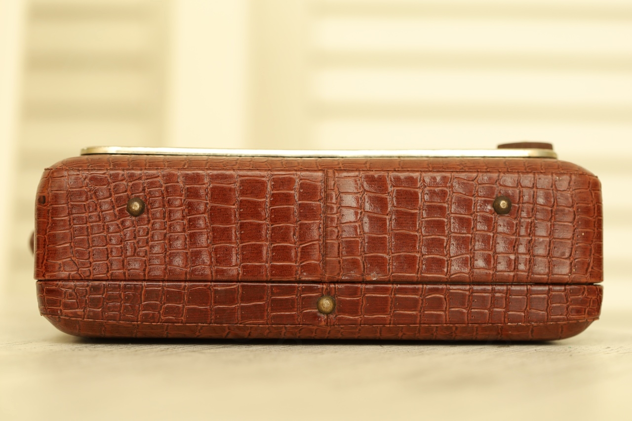
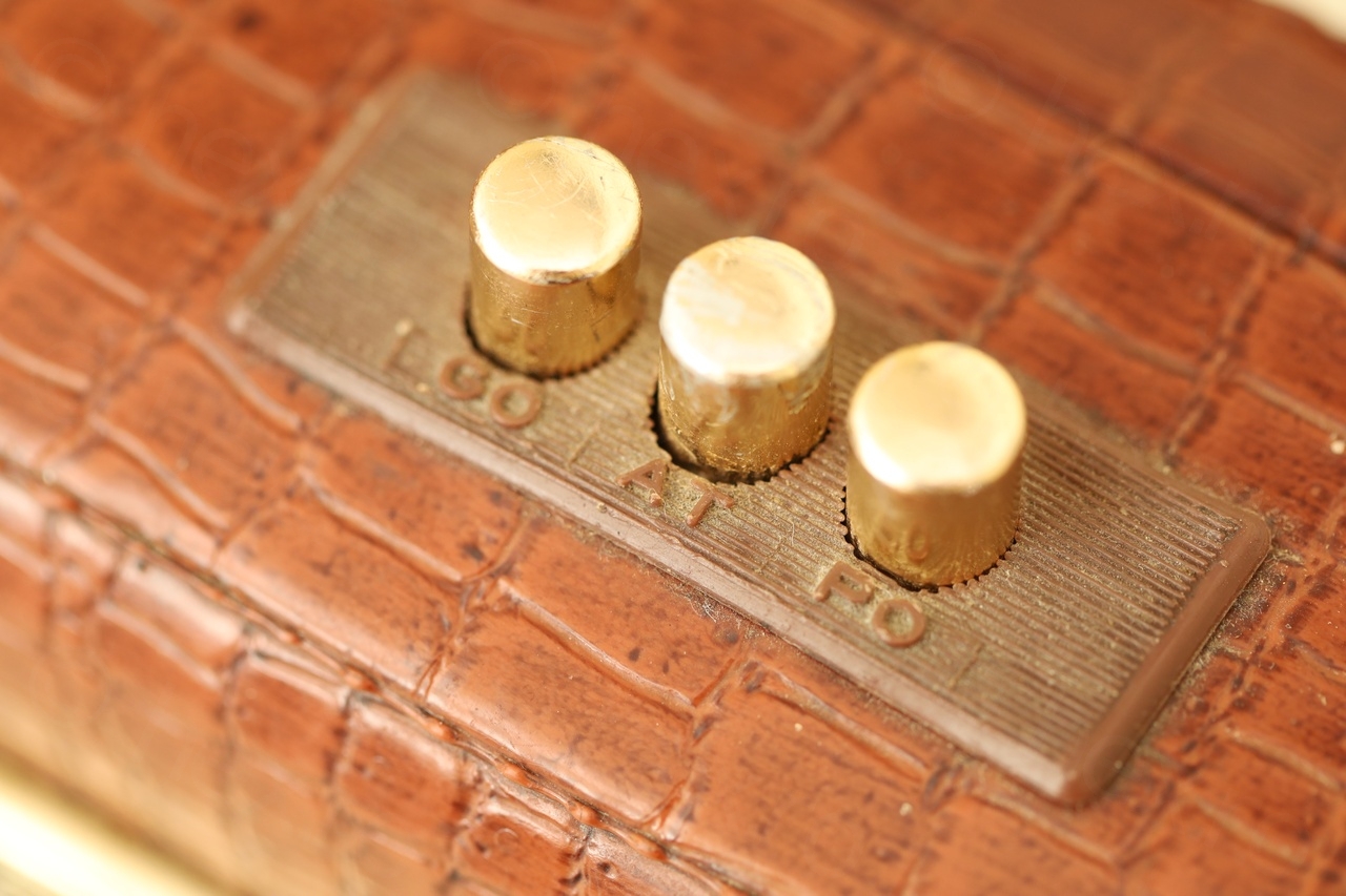
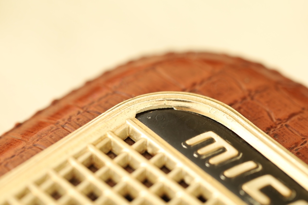
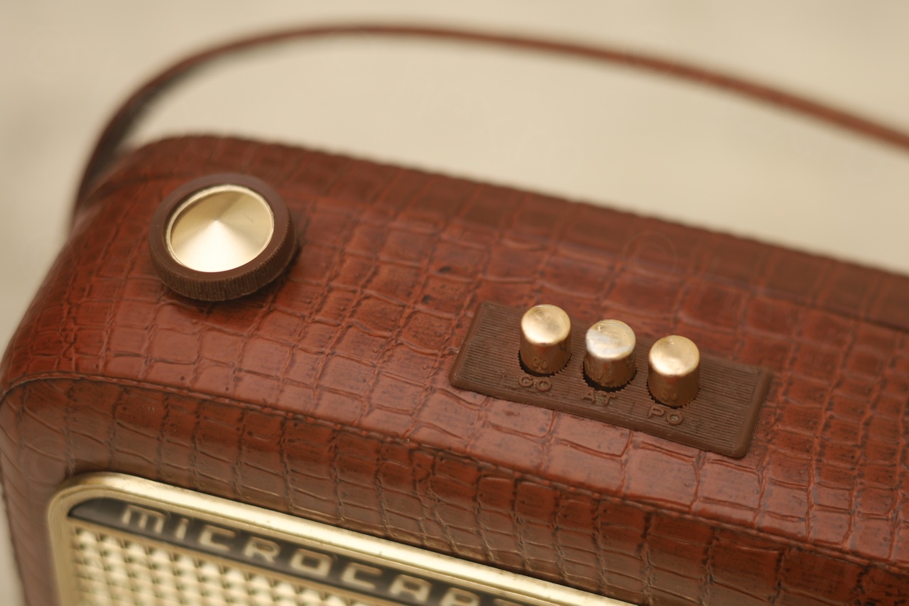
The radio is generally in very good shape. The Tuning knob took a hit and its pointy tip is no more. There’s a small piece of plastic missing from the inside of the front grill on top right and the band switch buttons lost some of their coating. However, the Volume knob is perfect and the crocodile vinyl / plastic cover is spotless.
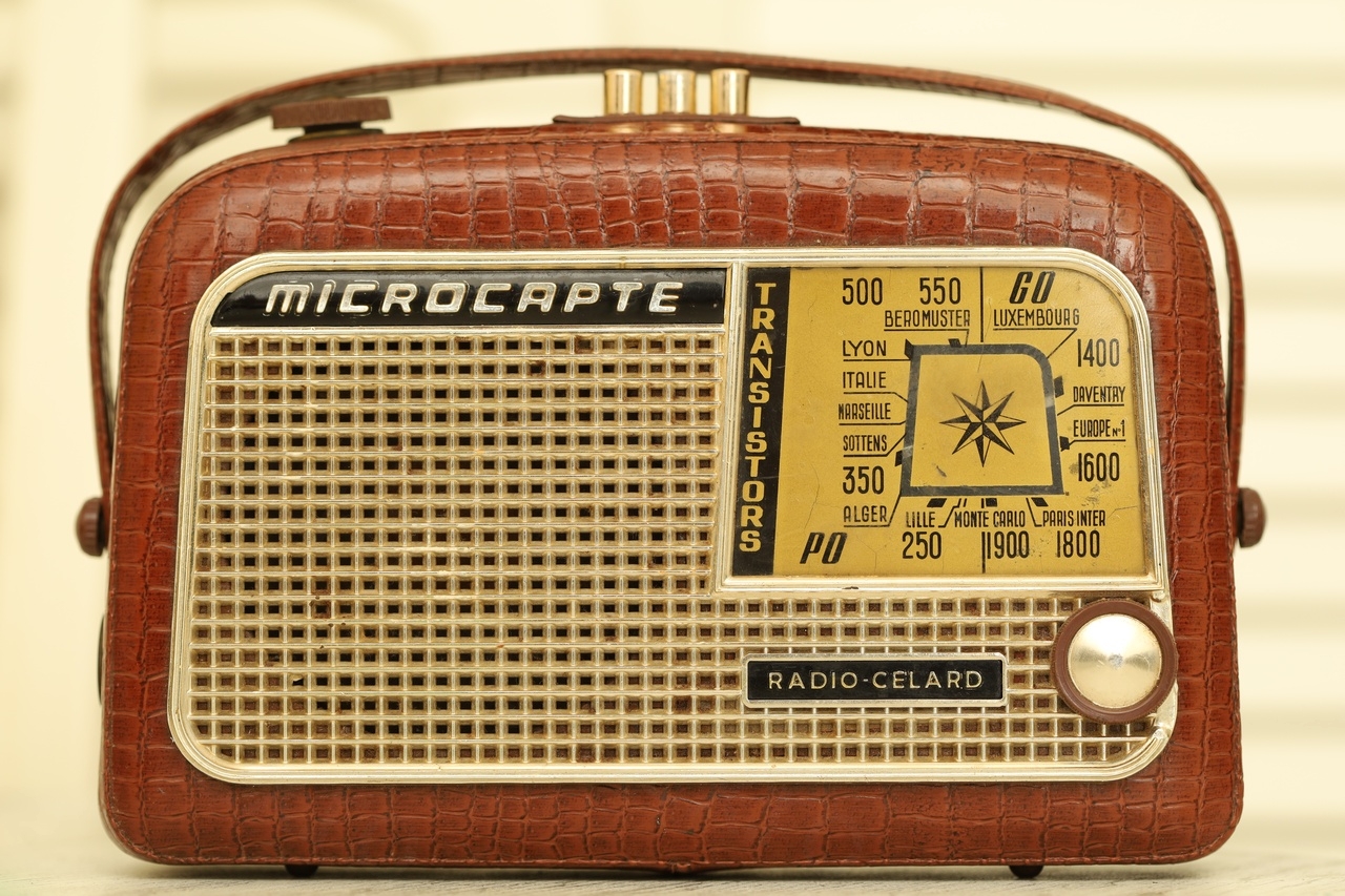

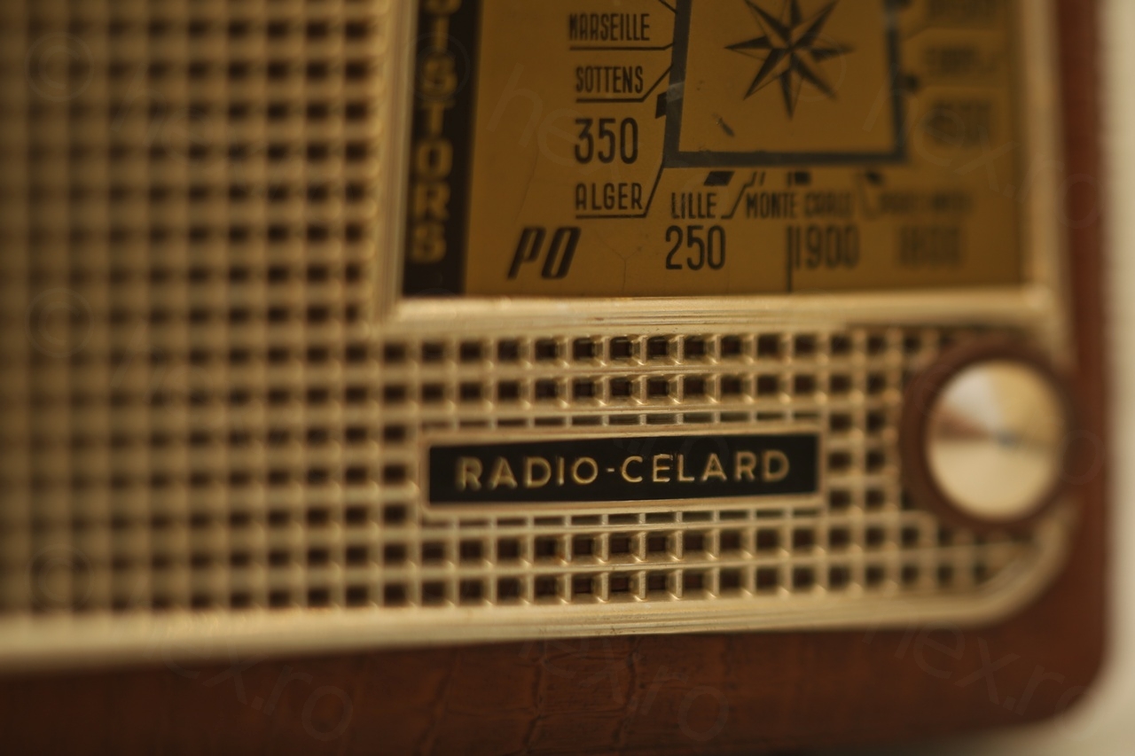
Given these minor visual aspects, I opened the radio and had a look inside – anxious, since this currently the oldest radio I am trying to restore. According to doctsf website – the radio was made in 1959.
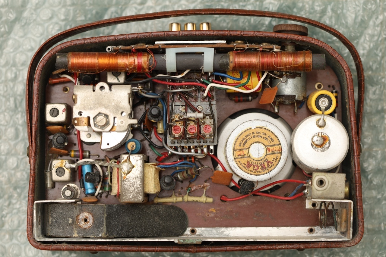
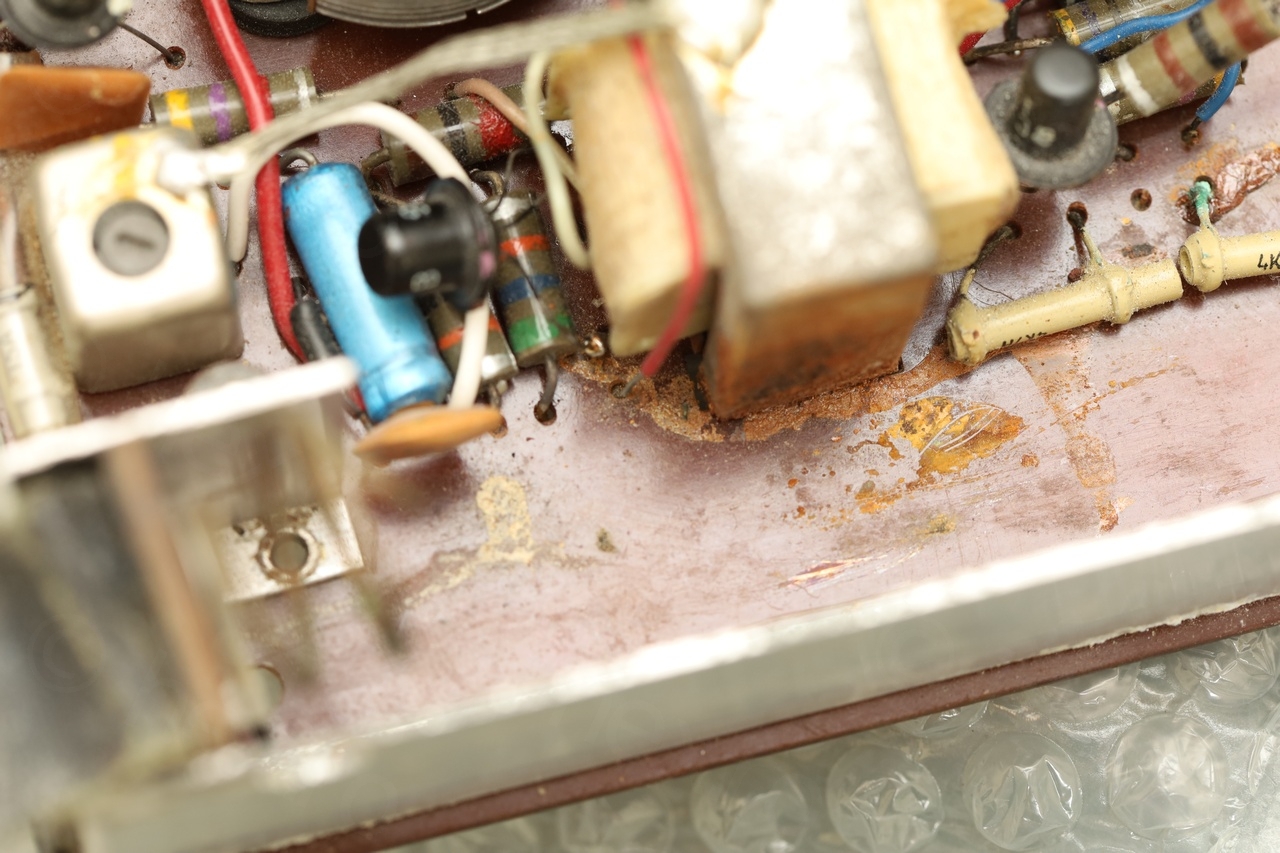
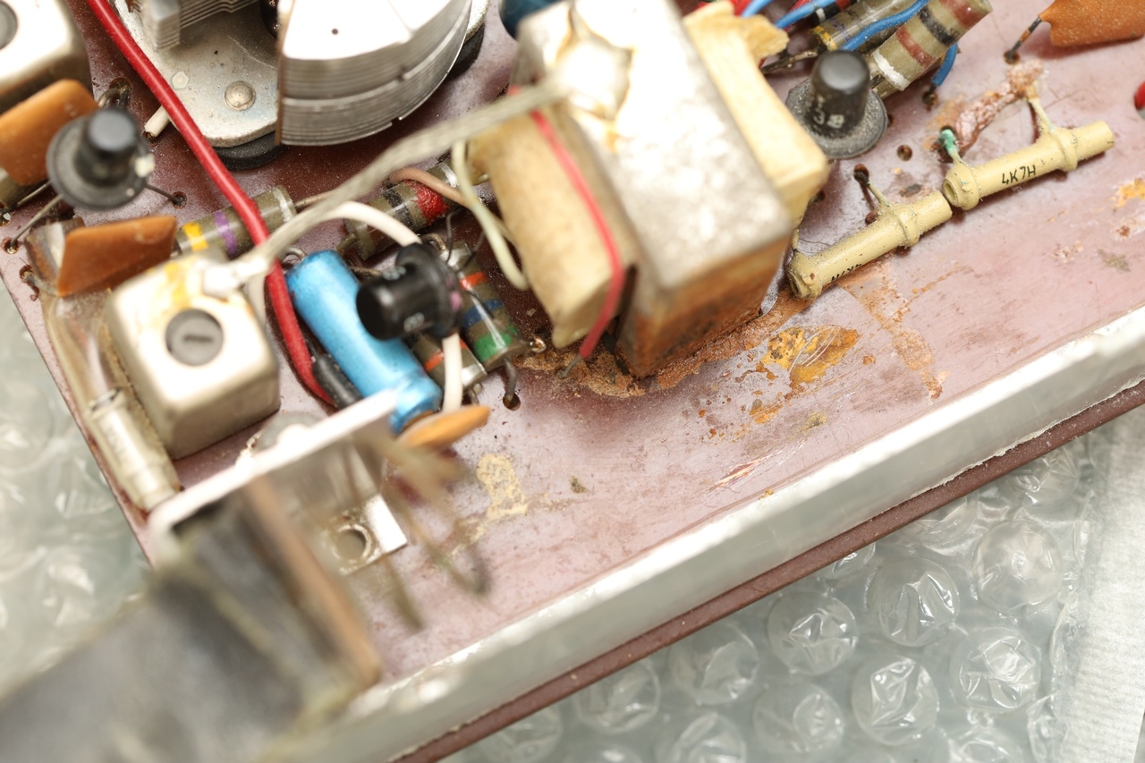
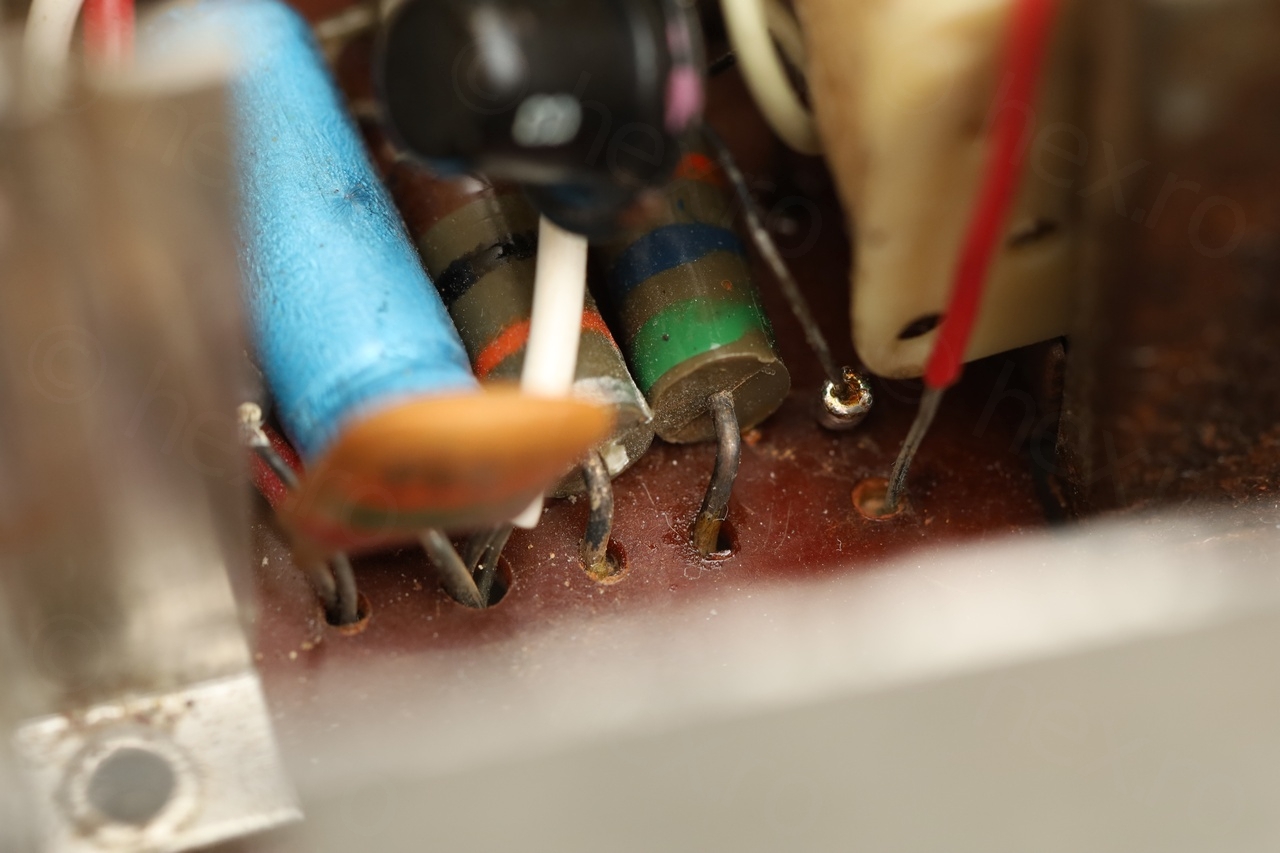
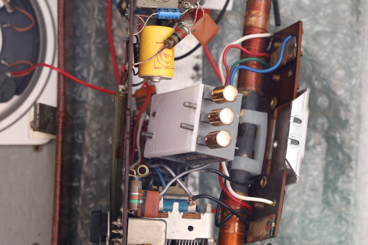
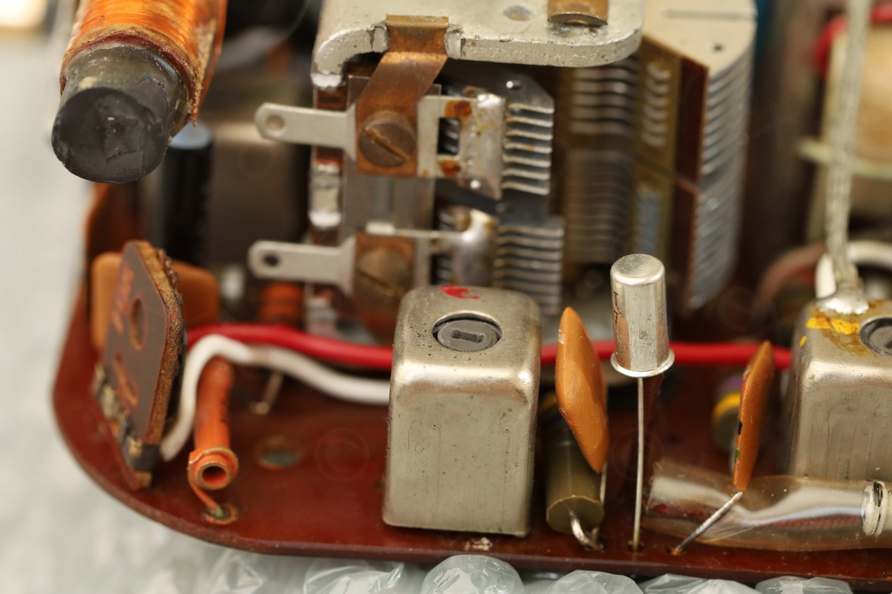
Interior aspect
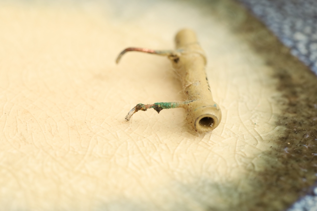
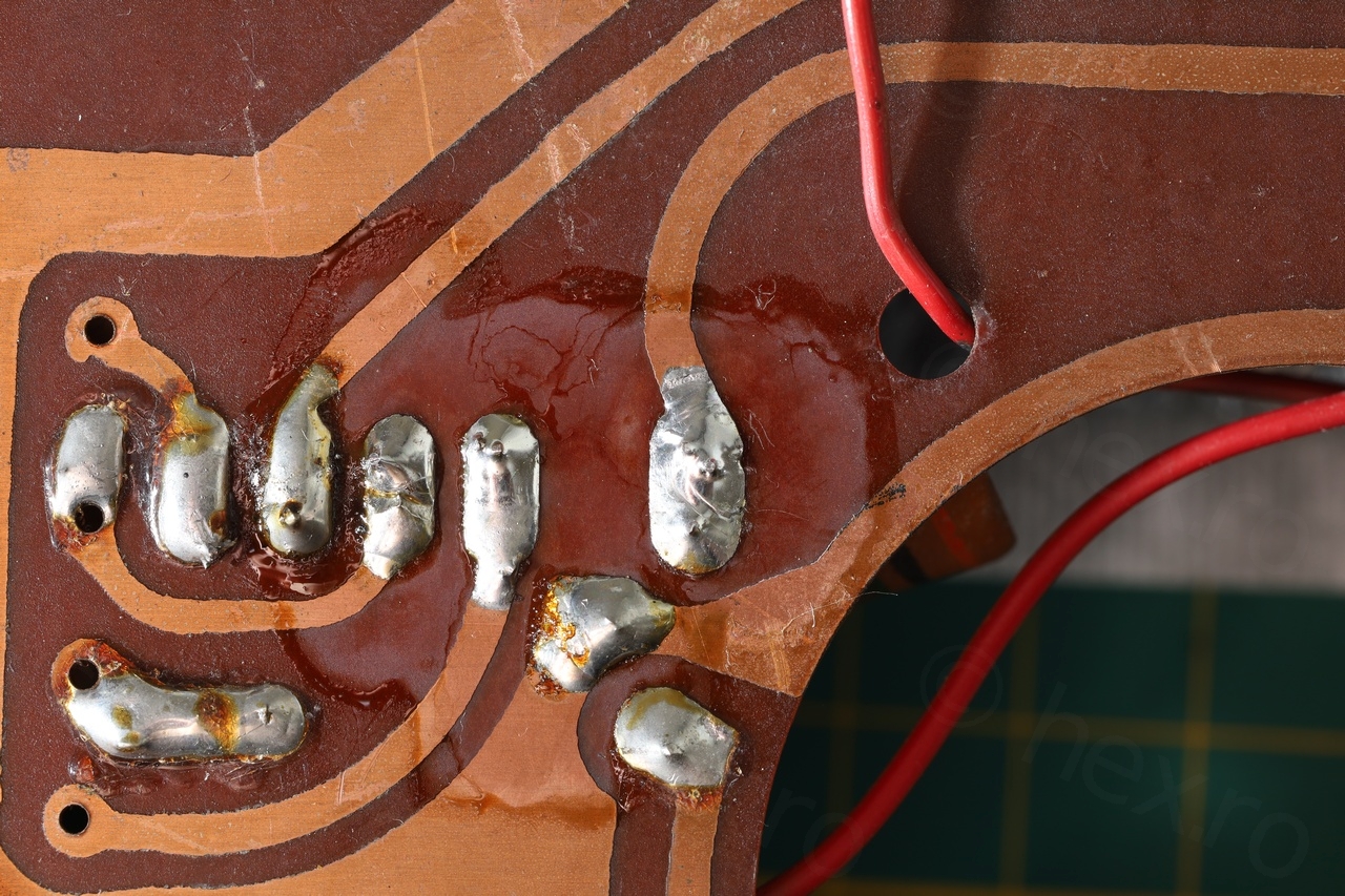
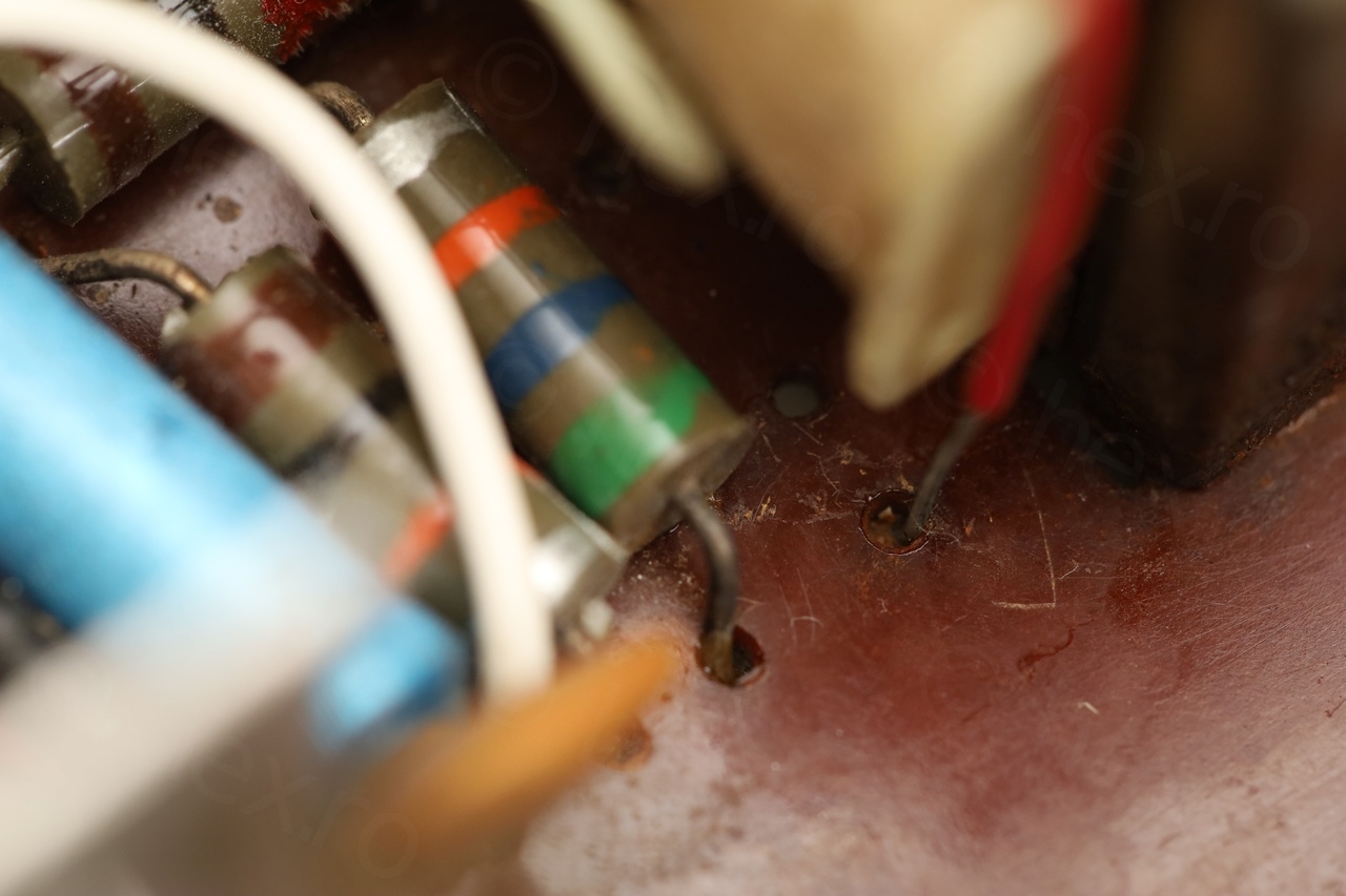
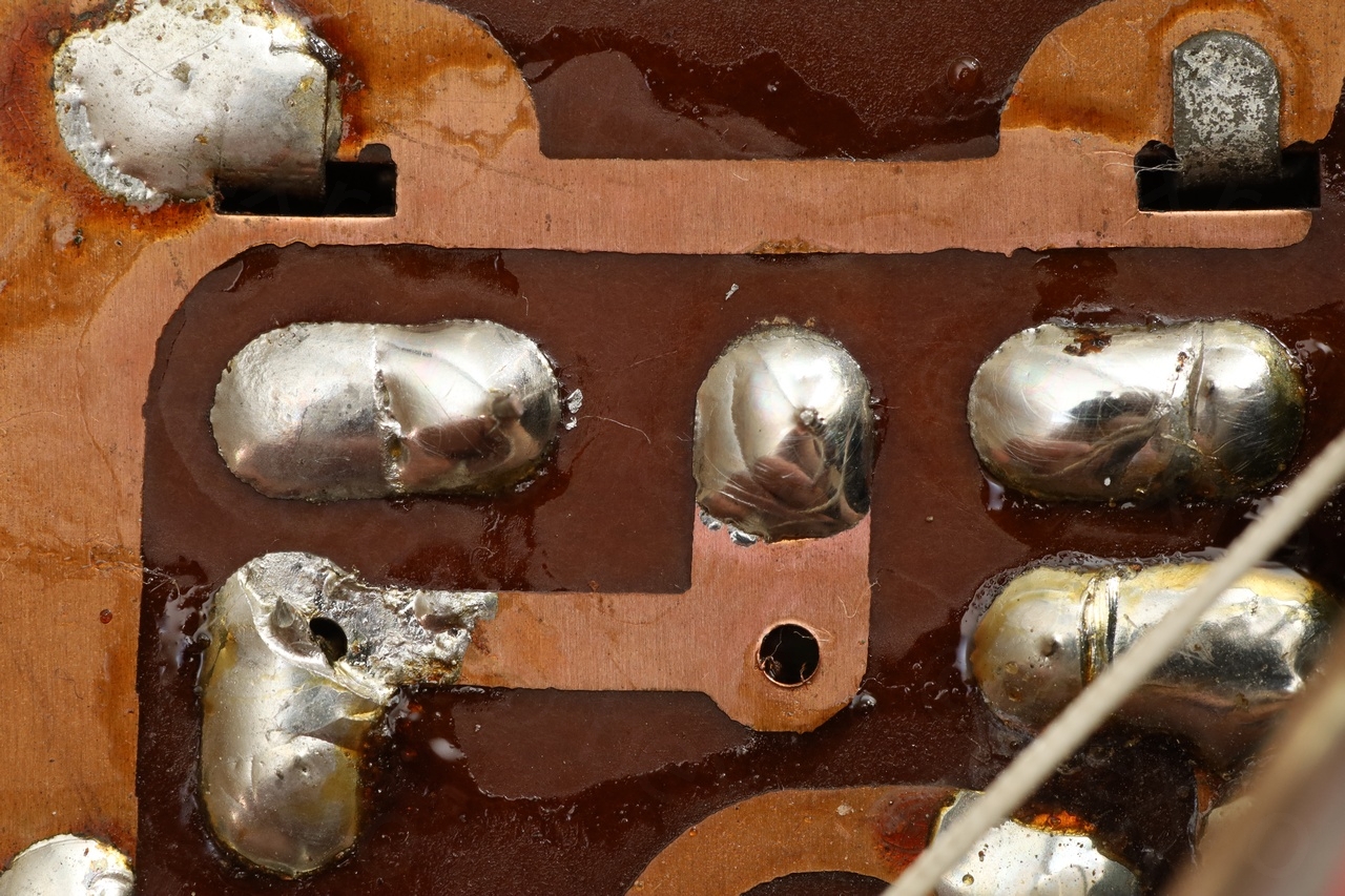
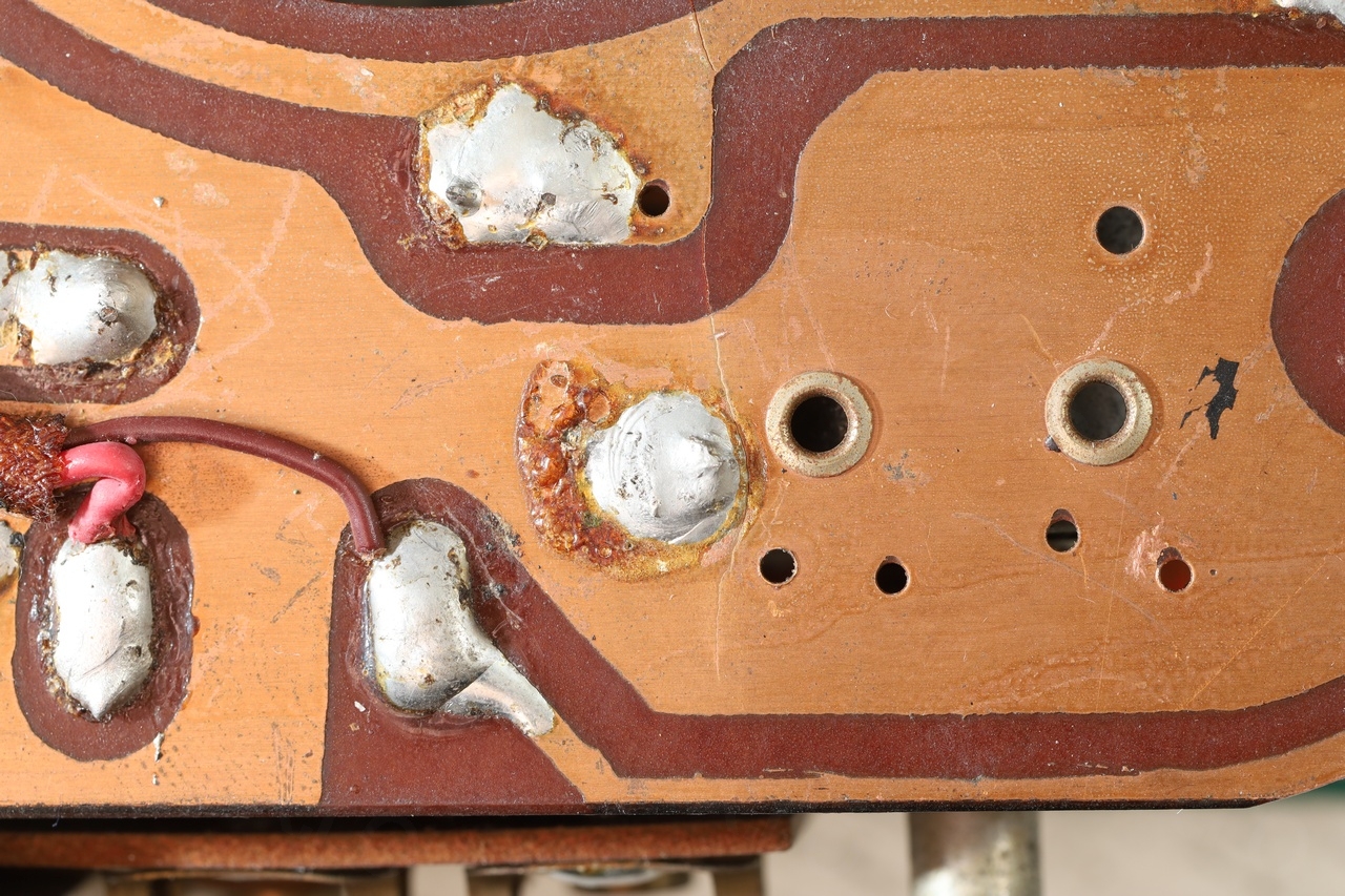
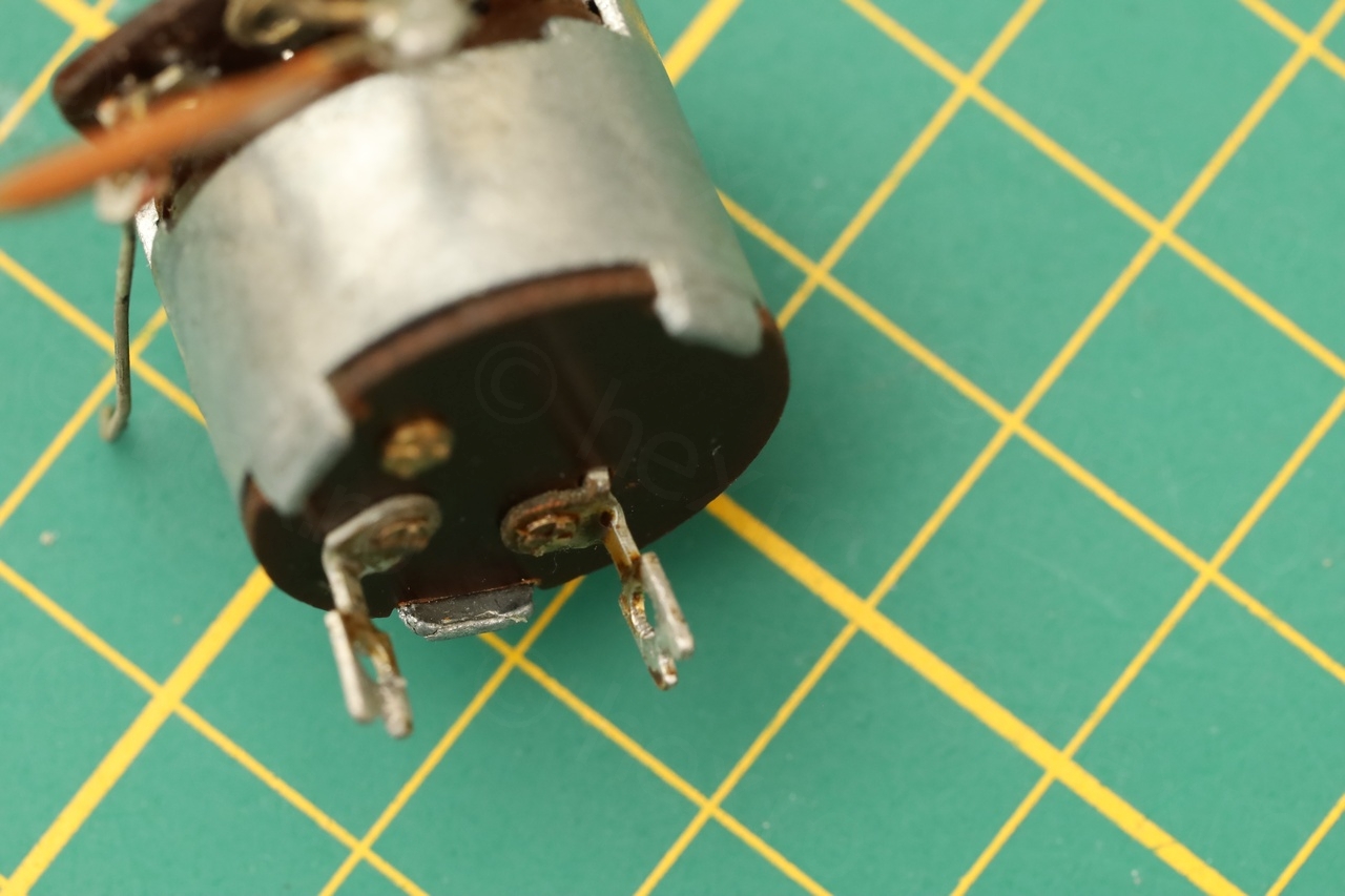
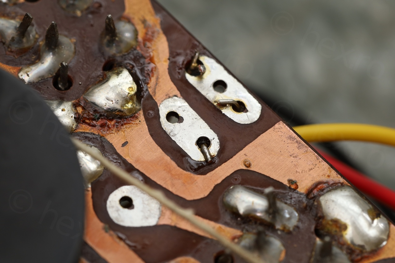
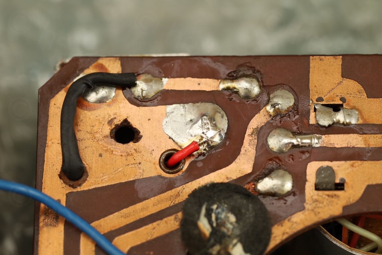
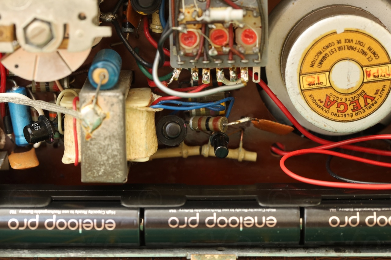
The insides were opposite to the exterior. Lots of corrosion on the bottom side of board. So bad that the leads of one amplifier transistor were destroyed and the transistor ended up being captured by the magnet of the loudspeaker:
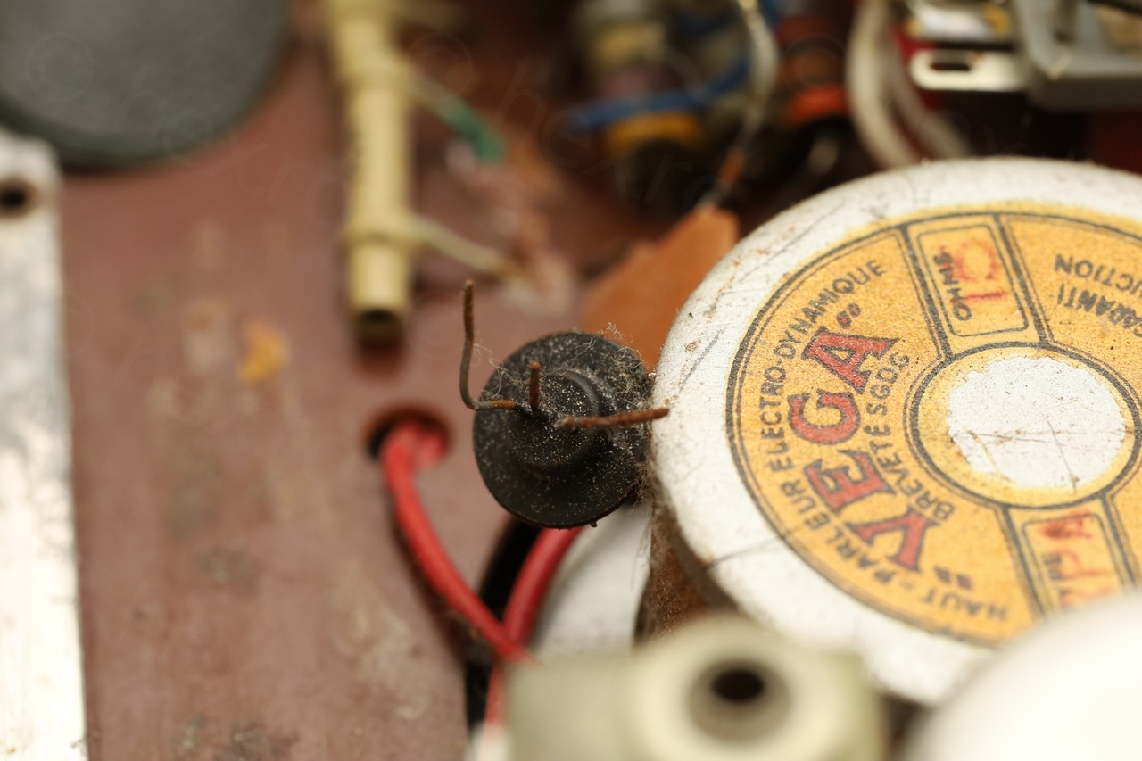
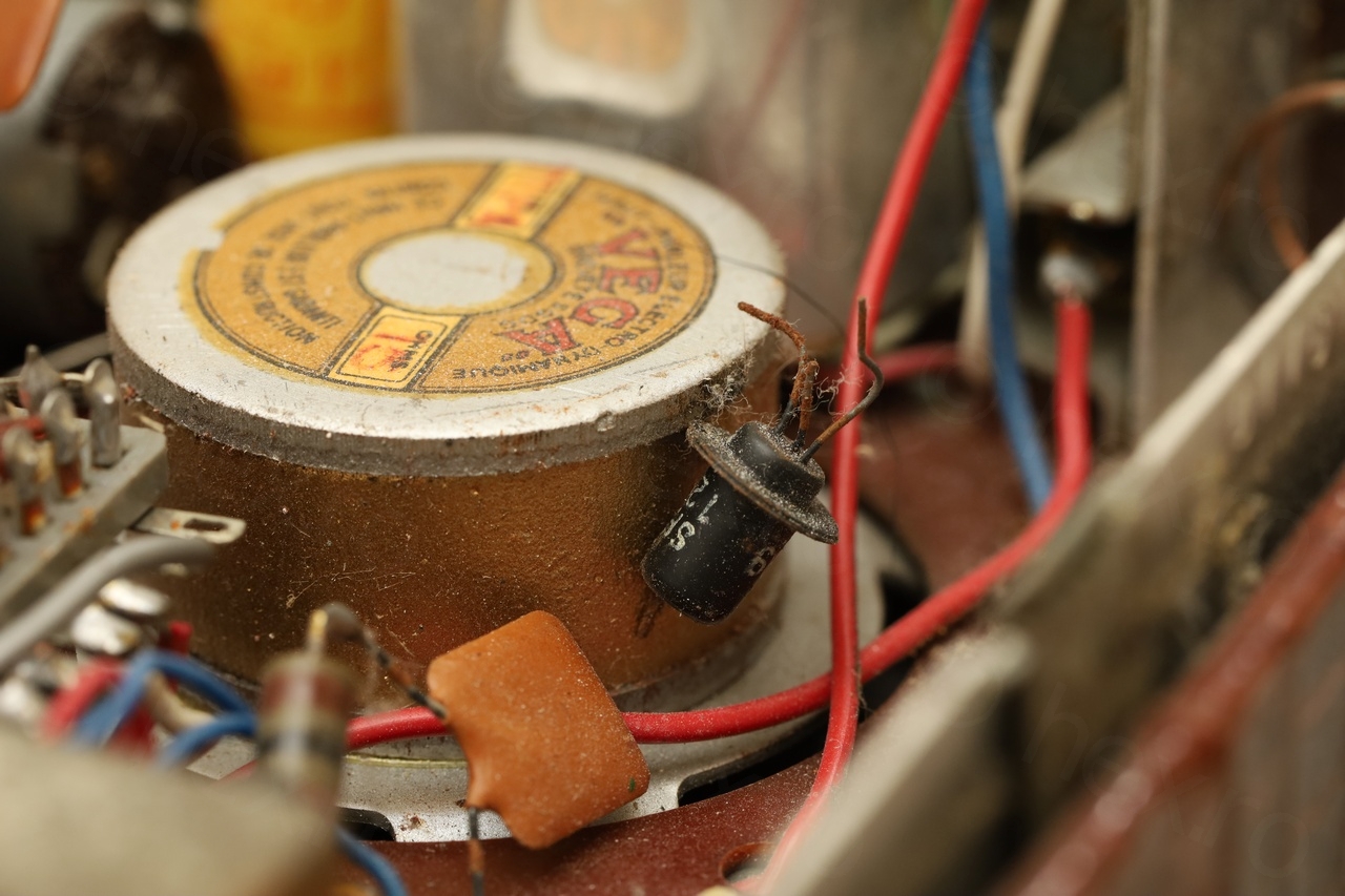
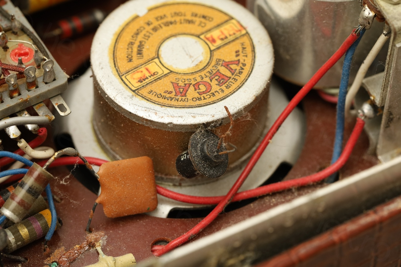
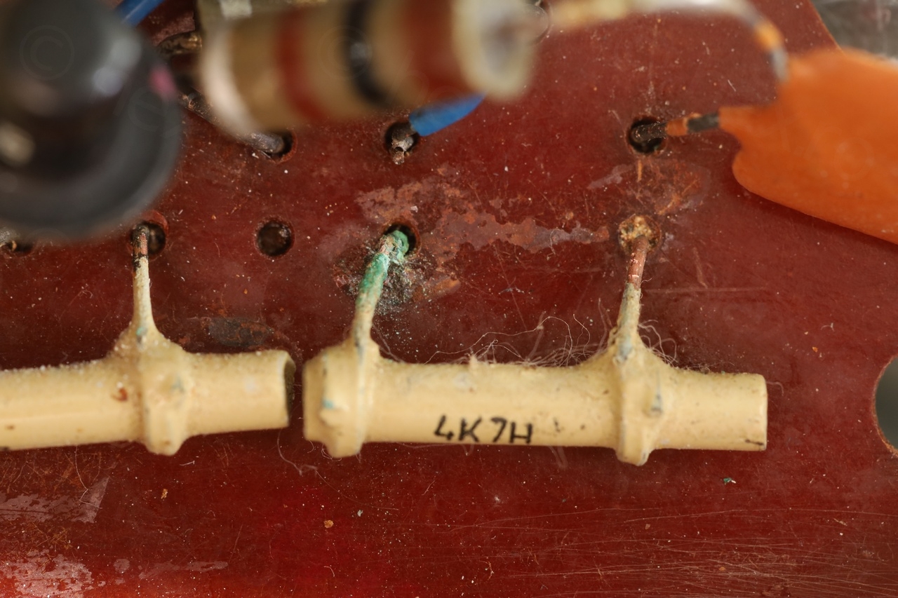
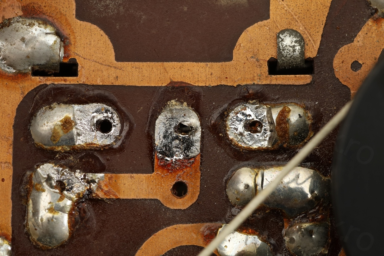
The one leftover leg was still attached to the board, very corroded:
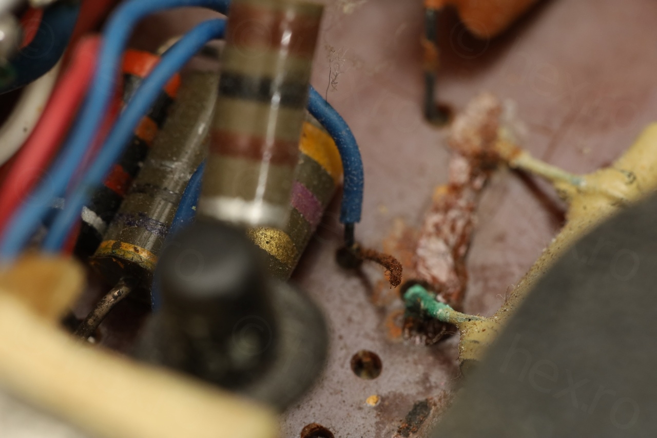
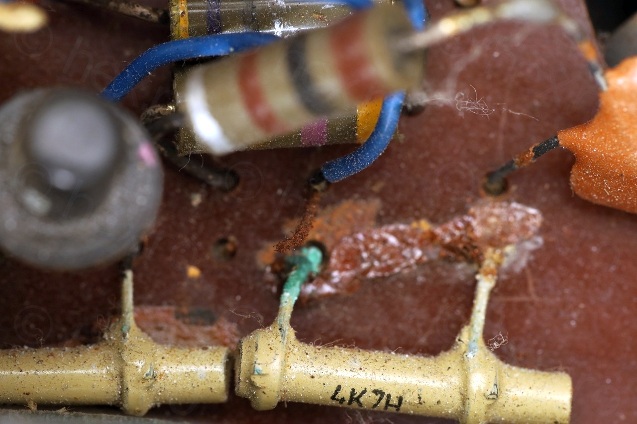
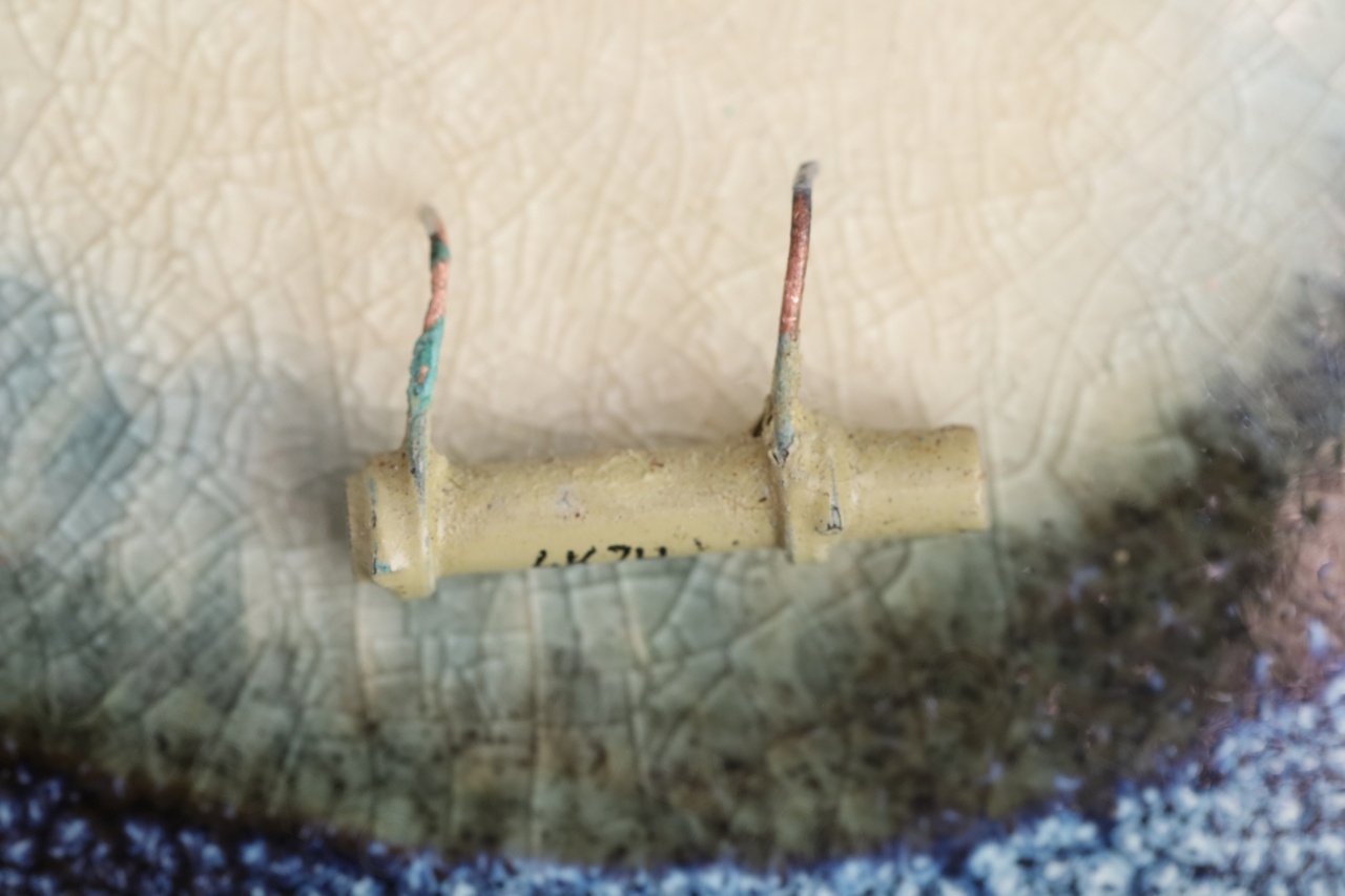
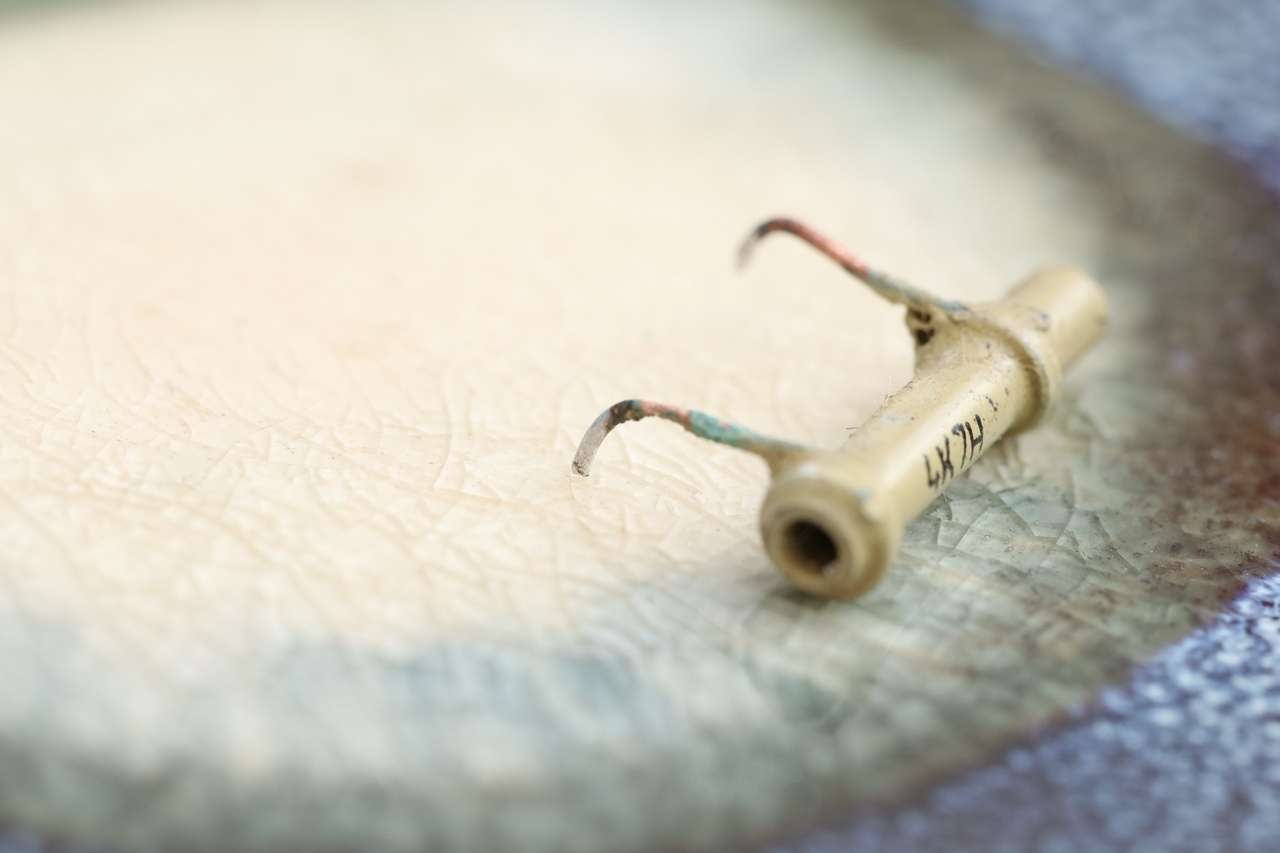
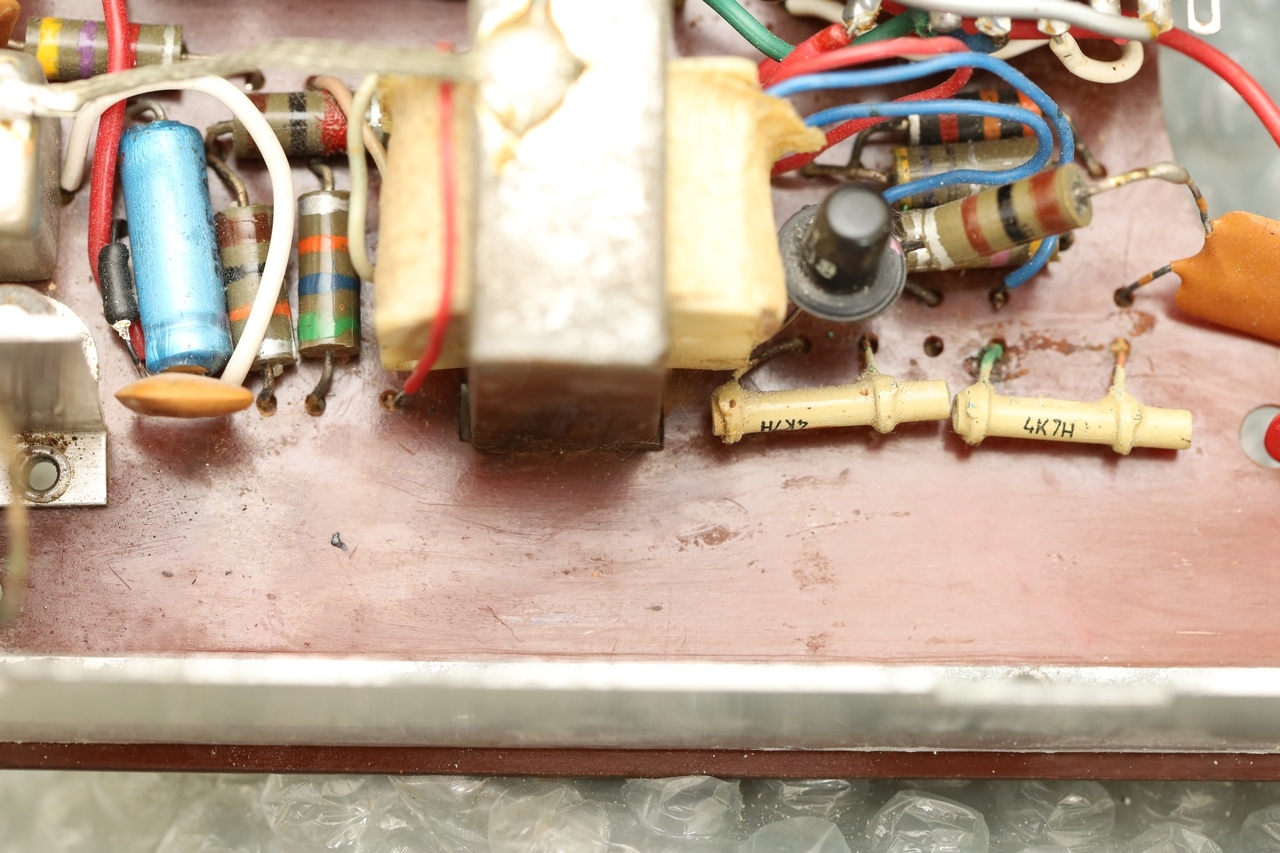
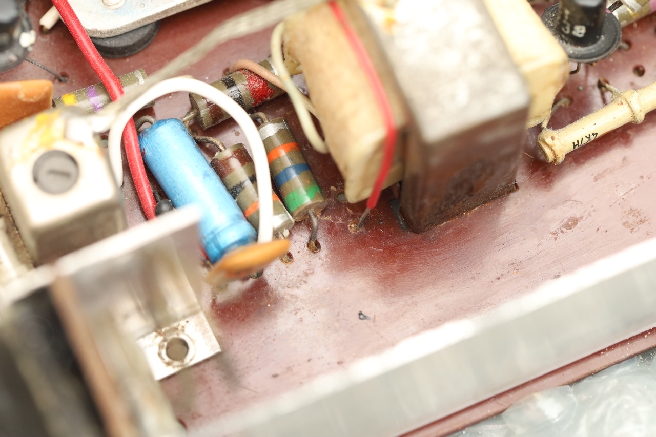
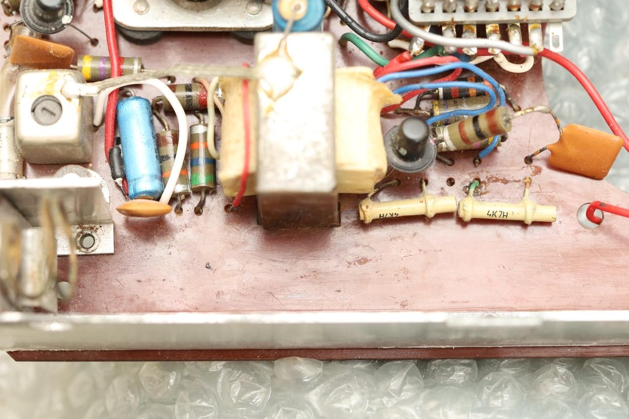
Investigating further, I found more traces of corrosion. One of the leads of the driver transistor (T4) was also eaten away by rust. Thankfully not all three!

Initially I was eager to try to power on the radio and find the faulty components, but had to postpone Power On until at least the two transistors are fixed somehow.
Schematics inadvertences
There are schematics out there for this specific model (both from doctsf.com and elektrotanya.com) however, the board on this radio has at least two differences.
There is a 50pF capacitor in series with a 100Ω resistor which are connected between the collectors of the output transistors (capacitor going to the collector of the T6 transistor). Also, the AVC resistor, on this model it is a variable resistor, but is marked as a fixed value resistor in the schematic.
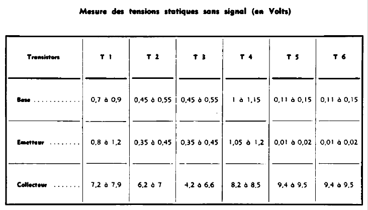
After searching around, I decided to use the schematic of the Radio Celard Babycapte. It seems the producer used the same schematic in various models of the time and they applied the improvement to the Microcapte too. The Babycapte schematic shows both the two additional components as well as the variable AVC resistor. Additionally, it has a very important table – the transistors voltages – which was very useful to help track down the problems.
I also found the schematic of the Transistor Capte 722 as it had a different set of transistors used (for the same apparent schematic). This comes in handy at the following step.
Replacing the corroded amplifier transistor (T6)
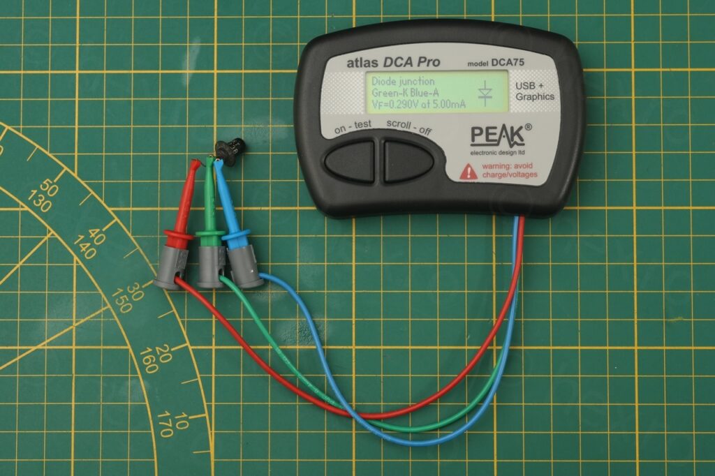
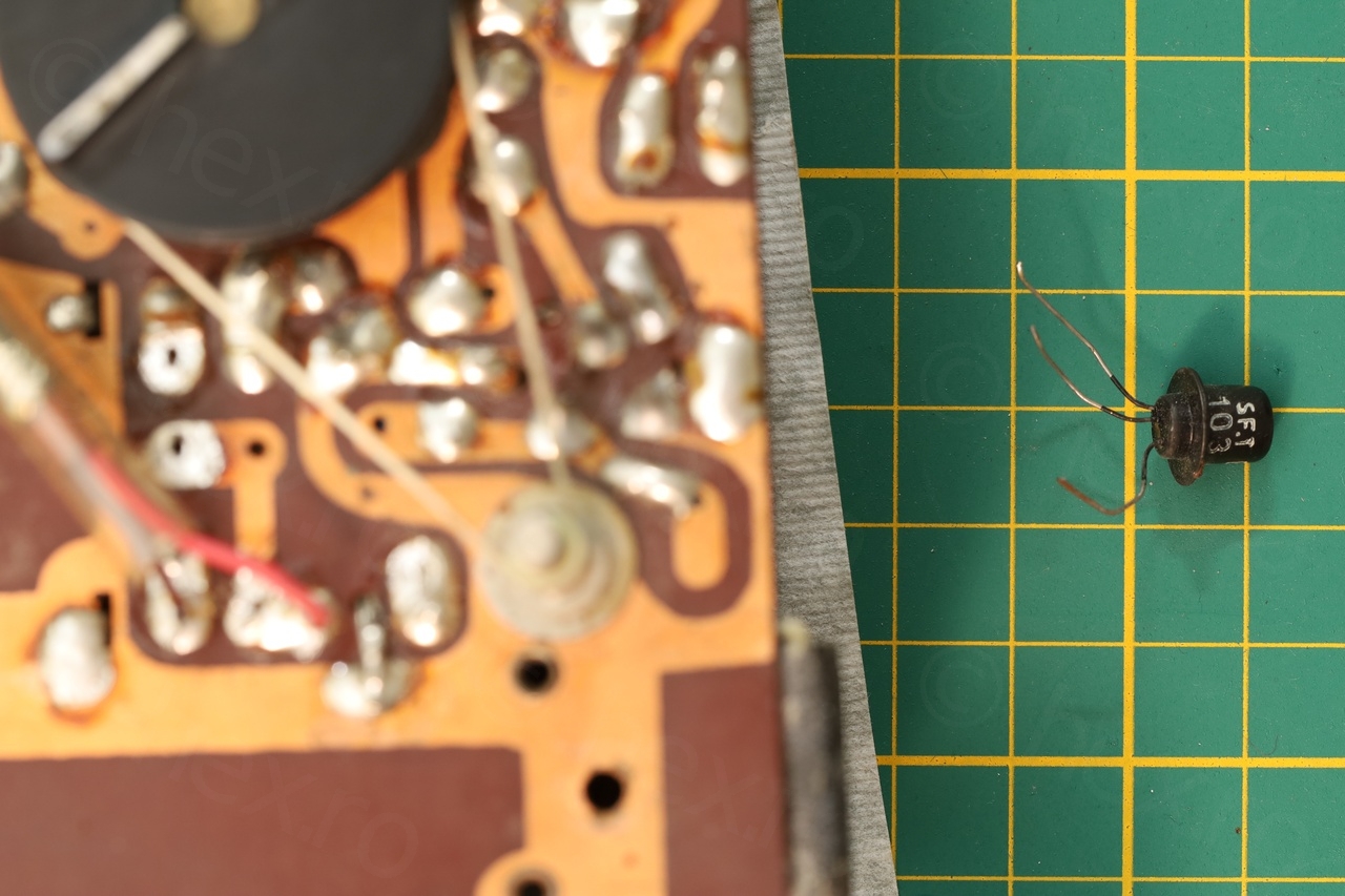
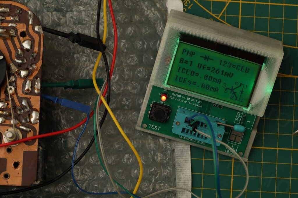
The transistor captured by the loudspeaker was a SFT123 transistor. It was defective, as you can see below, it tests only as a diode..
It was when I was wondering what would be a suitable replacement, I landed onto the Transistor Capte 722 schematic (1962), where, for the T5/T6 transistors, they were already using SFT323. I have some original SFT323 transistors which are black so it will preserve look of the radio!
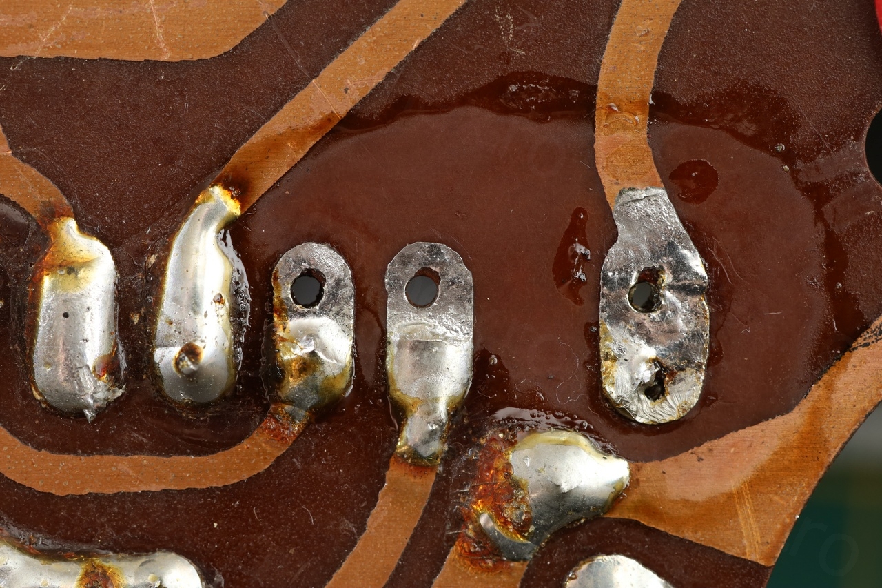
Next step was to first identify the right pins on the board. After taking two photos, flipping one horizontally and overlaying them in GIMP (with varying opacity, I was able to identify which pins are which:
Since this board also comes with the series R/C between the collectors of the amplifier transistors, it was also obvious that the corroded transistor was T6 (the one to which the 50pF capacitor is soldered too).
Before continuing though, the board had to be cleaned. The capacitor between B and C of T6 was also green of corrosion but its leg survived. So I decided to desolder it too and clean everything with IPA. Trouble is that the paint of the 4.7nF capacitor becomes gooey with IPA, but I was careful enough not to destroy it.


This at least should take care of the fix. By this time I have already found out that the speaker works correctly. Without having the signal generator at hand – I tried to use the component tester directly on the leads of the existing SFT123 transistor (T5). The speaker was alive!
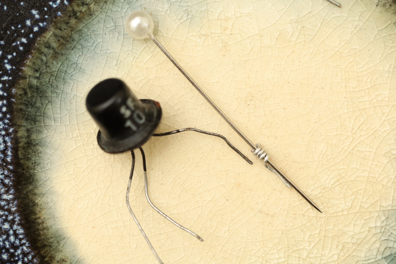
Rebuilding the corroded lead of the driver transistor (T4)
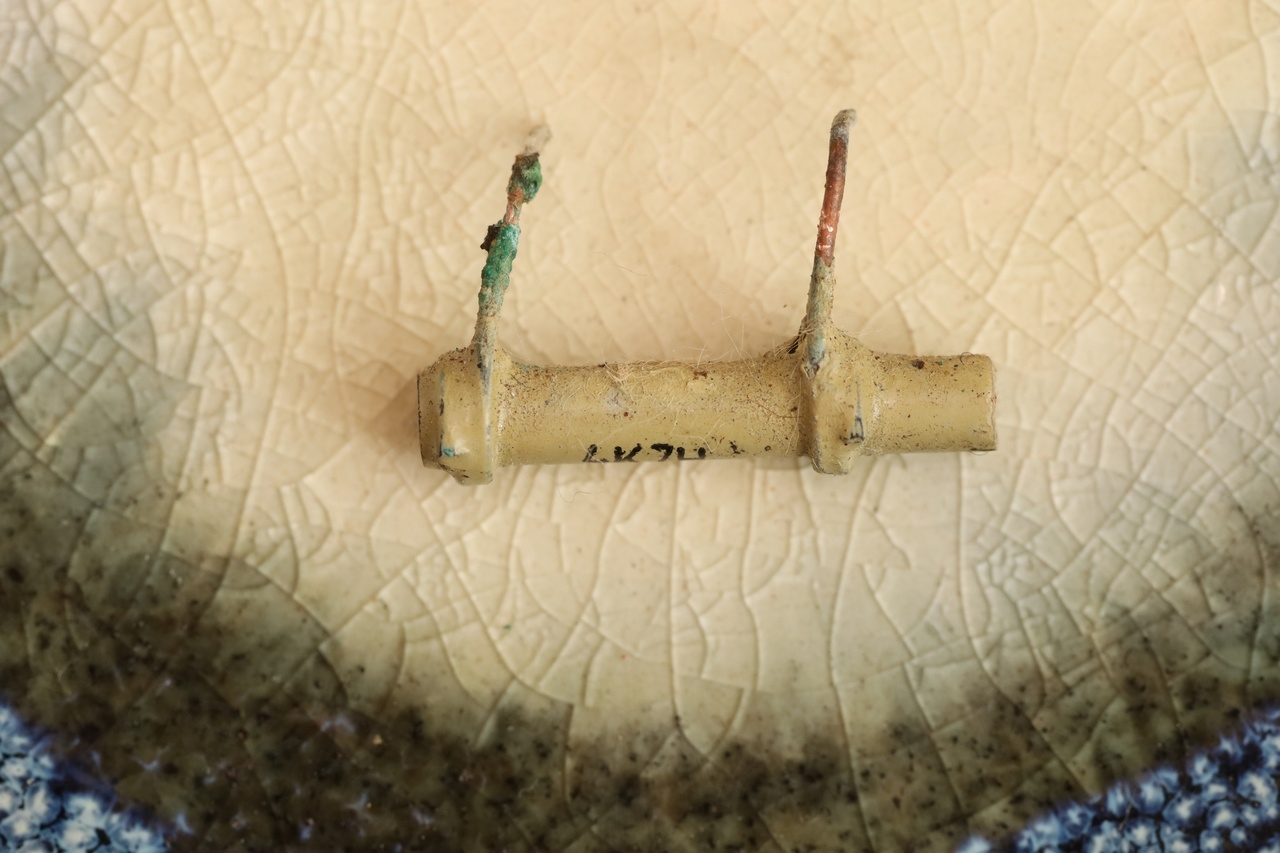
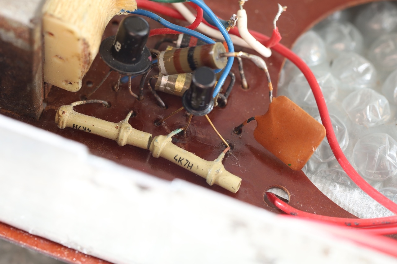
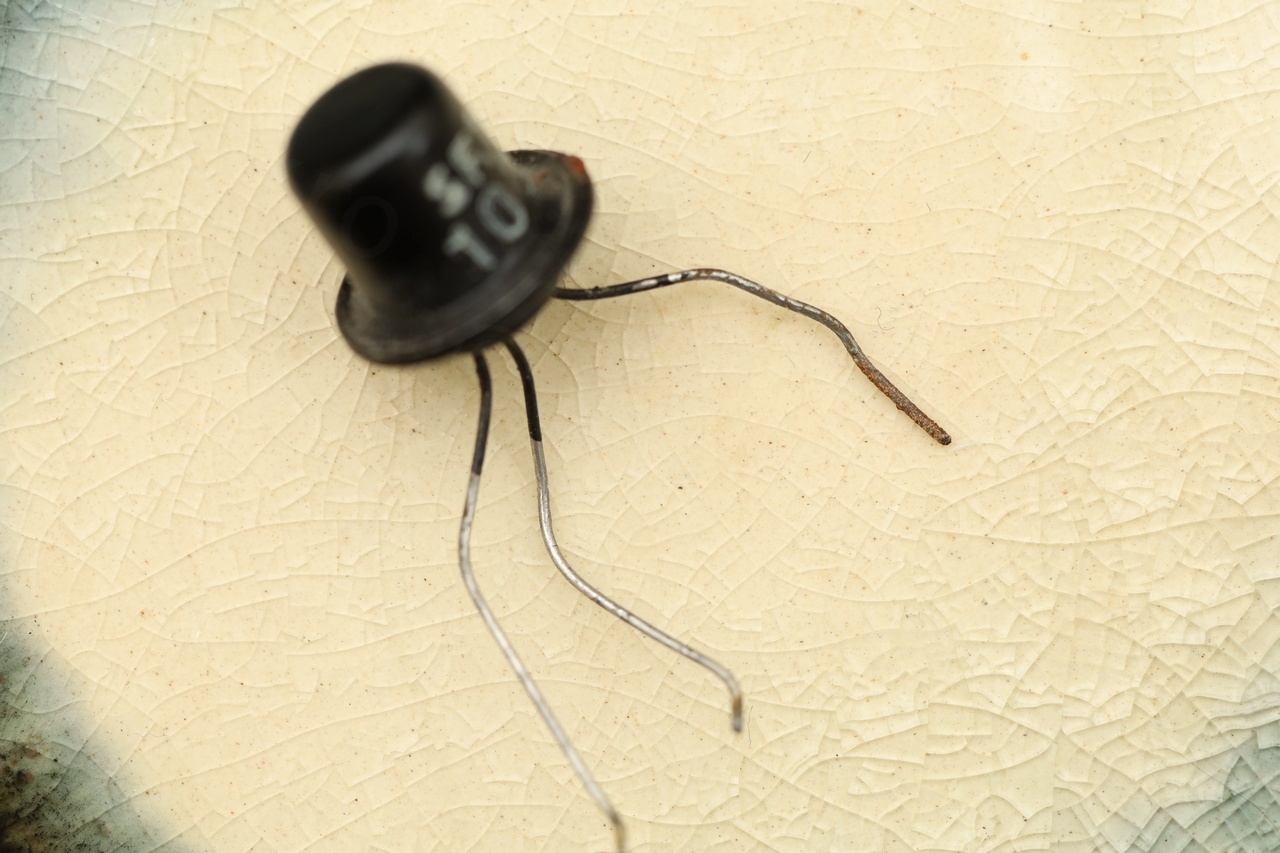
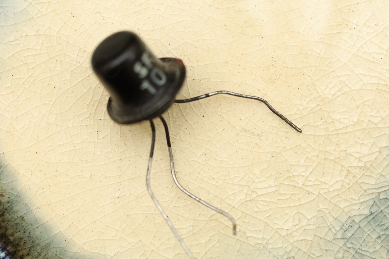
Having a closer look at the T4 transistor (SFT103) I realized that maybe it can be salvaged! The corrosion seemed to only have affected the Collector lead, the transistor was still measuring fine.
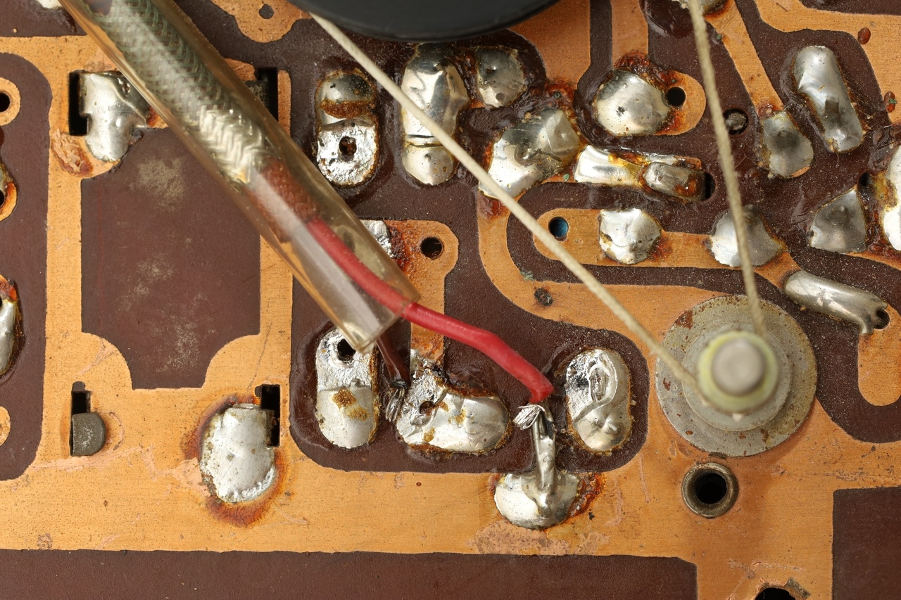
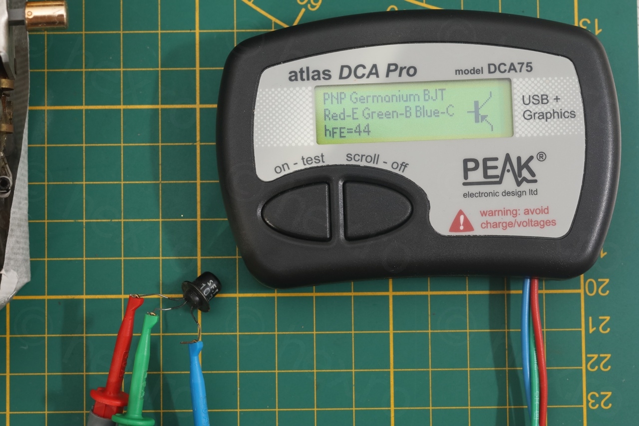
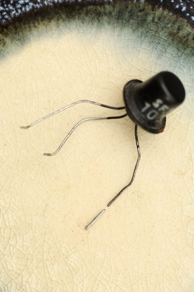
I was unsure how to proceed or how to extend the shorted lead. But for sure, it needed to be cleaned first:
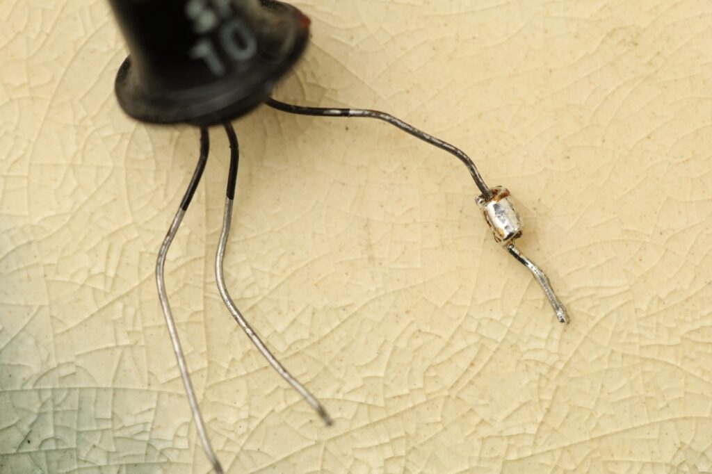
I considered first just cutting a piece of a lead of a donor component, and just trying to solder it to the transistor leg:
This seemed easy, but then I realized that is creates a problem when trying to solder it back. The circuit board traces are so wide, that my 90W soldering gun is at its limits – too much copper that dissipates the heat. This would mean that by the time I finish soldering the transistor, the little blob of solder that would keep the to parts of the lead will also melt. Not good.
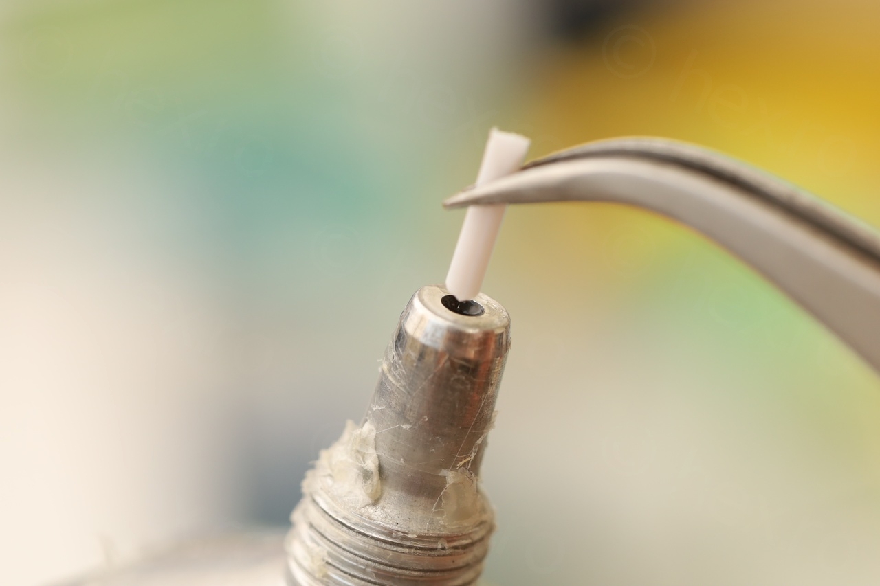
Finally, I realized I need a more sturdy way to extend the lead of the transistor:
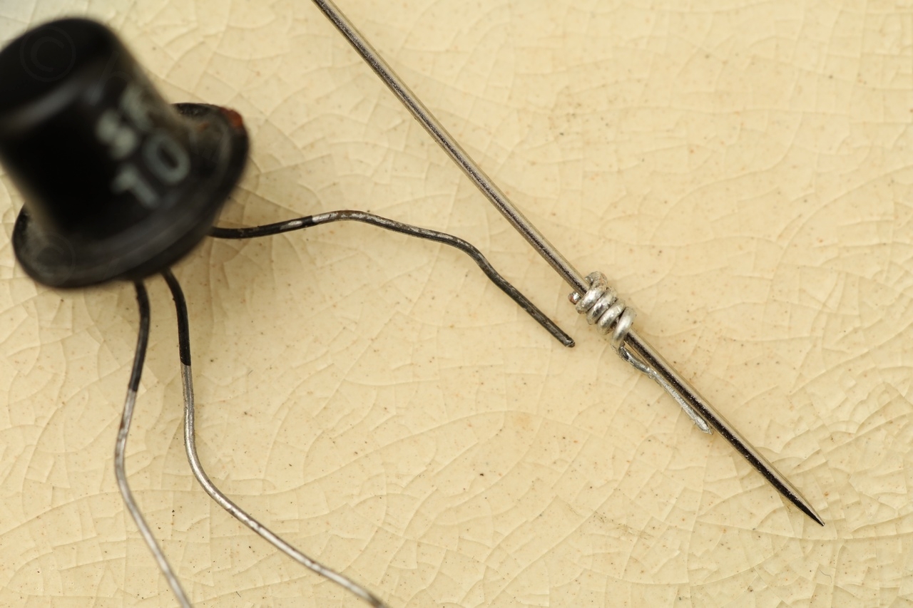
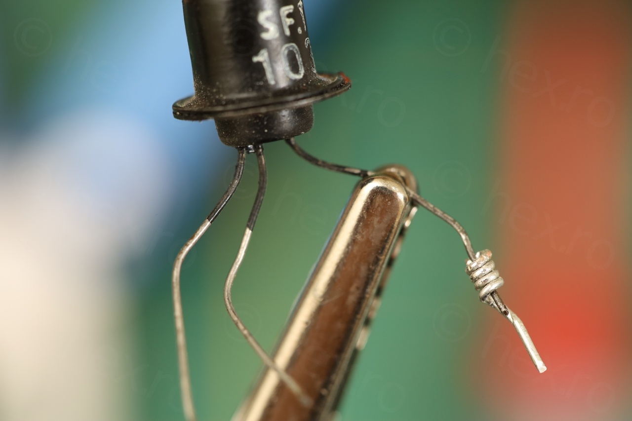
Results:
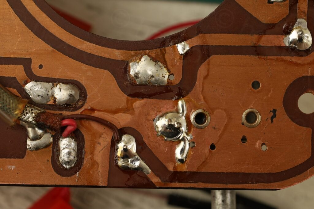
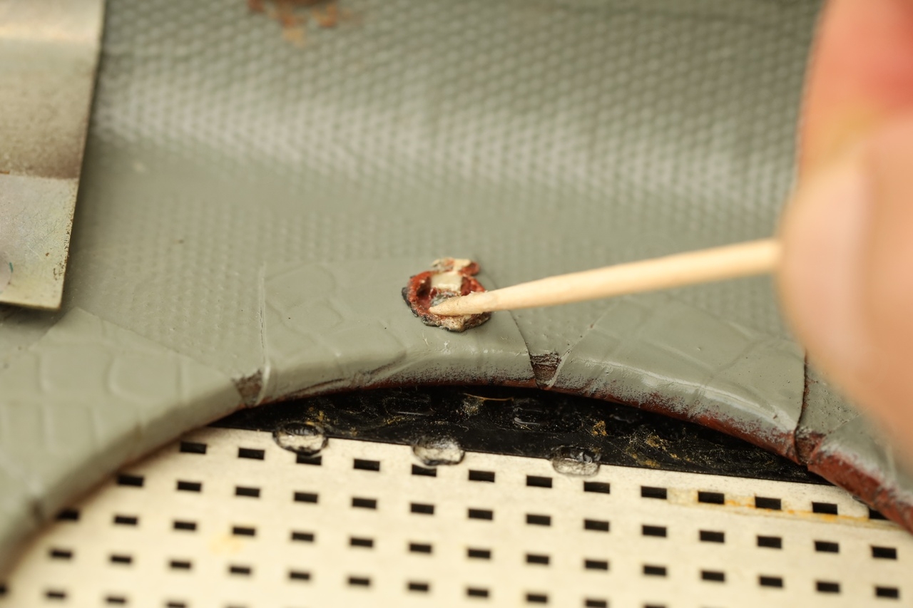
Before plugging the transistor back, I took the opportunity to clean the board of the accumulated rust / corrosion.


I had to remove rust the transformer case using a fine steel brush, scrape away the encrusted rust with the same brush. With copious amount of IPA and cotton buds:
Finally, the driver transistor could be installed:
The extension held very nicely and the transistor lead did not escape its grip, even while soldering it.
Diagnosing missing Collector voltage for final amplifiers
In this radio (because is a Germanium one), the Battery ‘-‘ goes to VCC and Battery ‘+’ represents GND. The voltages given in the schematic of Babycapte were measured with the voltmeter GND on Battery “-” , so voltages appear positive:
After reconnecting the two transistors (the missing one + the driver one with lead extended), there was still no sound coming from the speaker.
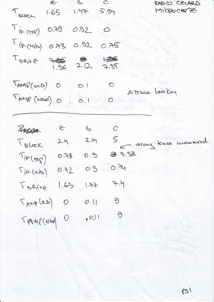
I measured the voltages on each of the transistors (top part of the measurements below) and was surprised that the Collectors of both the amplifier transistors were at 0V! According to the schematic of Babycapte, the Collector(s) have to be at >9V. I also noticed that the T2 had the Collector to 0 (but this was my mistake measuring the wrong trace).
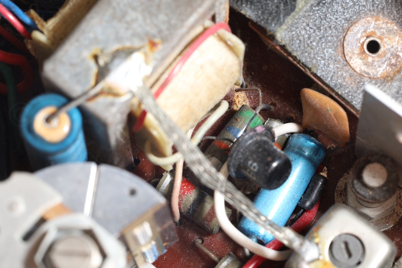
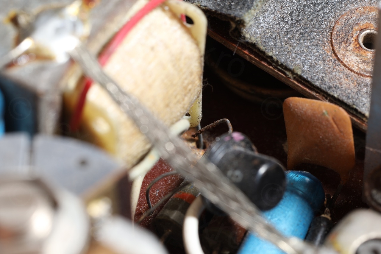
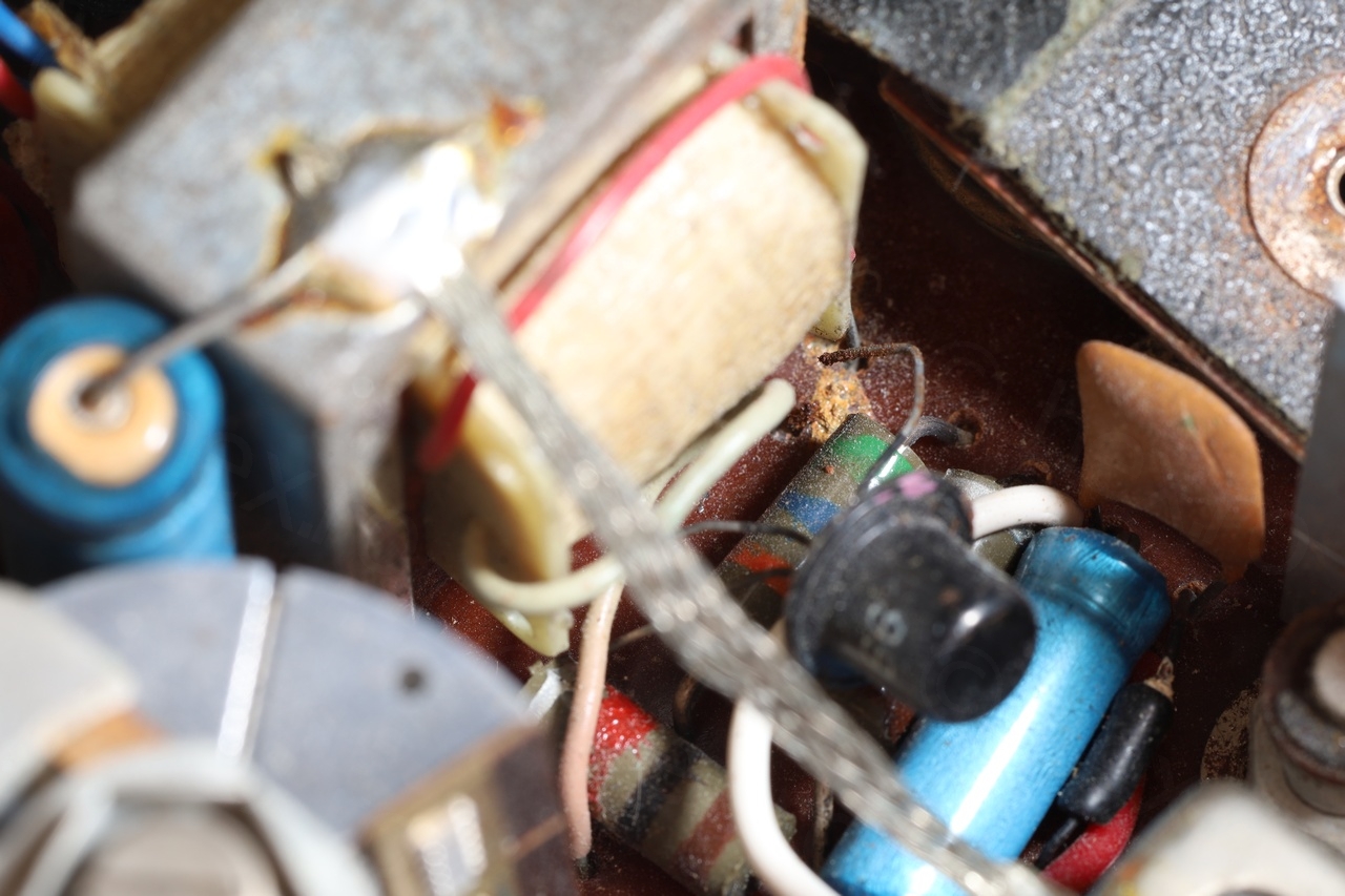
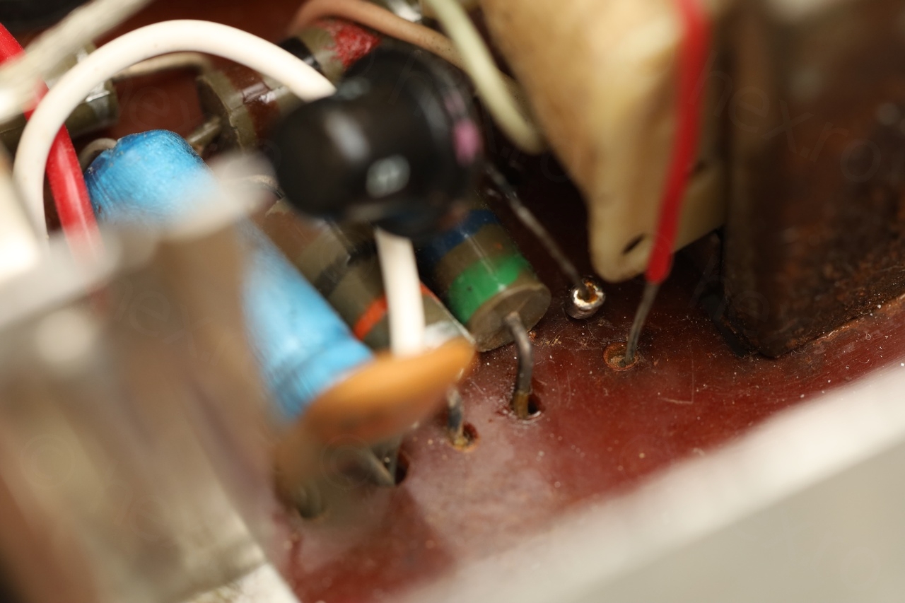
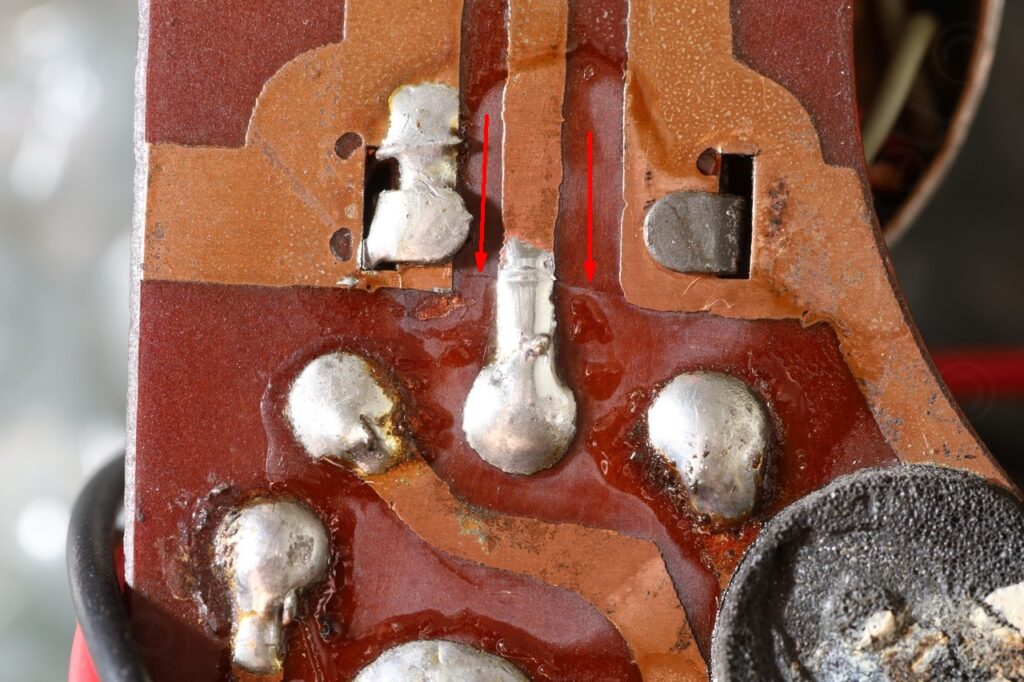
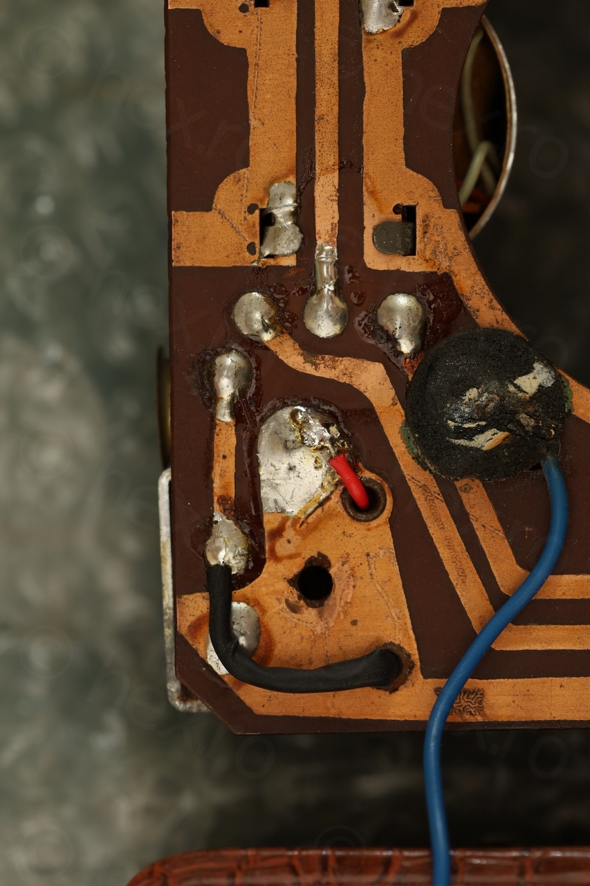
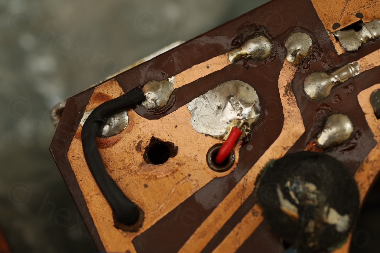
Doing a continuity test on the center tap trace (that was supposed to bring the 9V to the Collectors) helped locate a very fine crack:

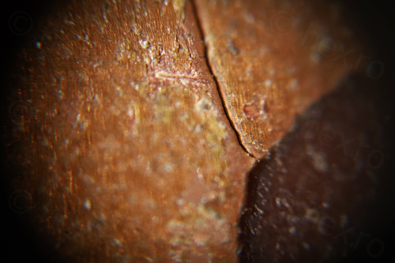
The crack spread and almost broke the GND track that was running alongside.
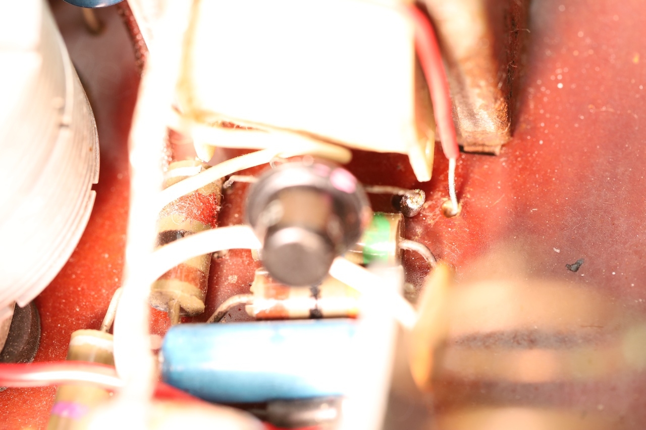
Unfortunately, these were not the only broken traces. While standing the radio vertically, a slight pressure on the top side would make the audio quiet. After more searching, found another crack:
I would argue that the slight deformation on the radio’s case, this poor radio fell somehow which caused this long cracks to appear. Traces were around the area of the big audio output transformer. Not sure if there is a better fix, no glue brings back the initial factory strength when it comes to flexing.
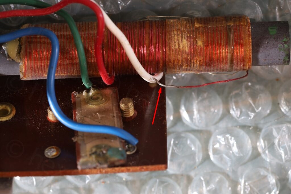
Fixing a cut Litz wire
After fixing the broken traces and having the transistors reinstalled, the radio had zero sensitivity and faint volume. It would sense a very strong signal from a a nearby SMPS, but no chance of tuning to a real far away MW/LW station.
Lack of sensitivity was hard to diagnose.
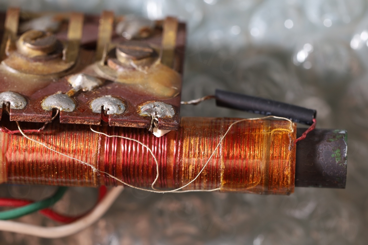
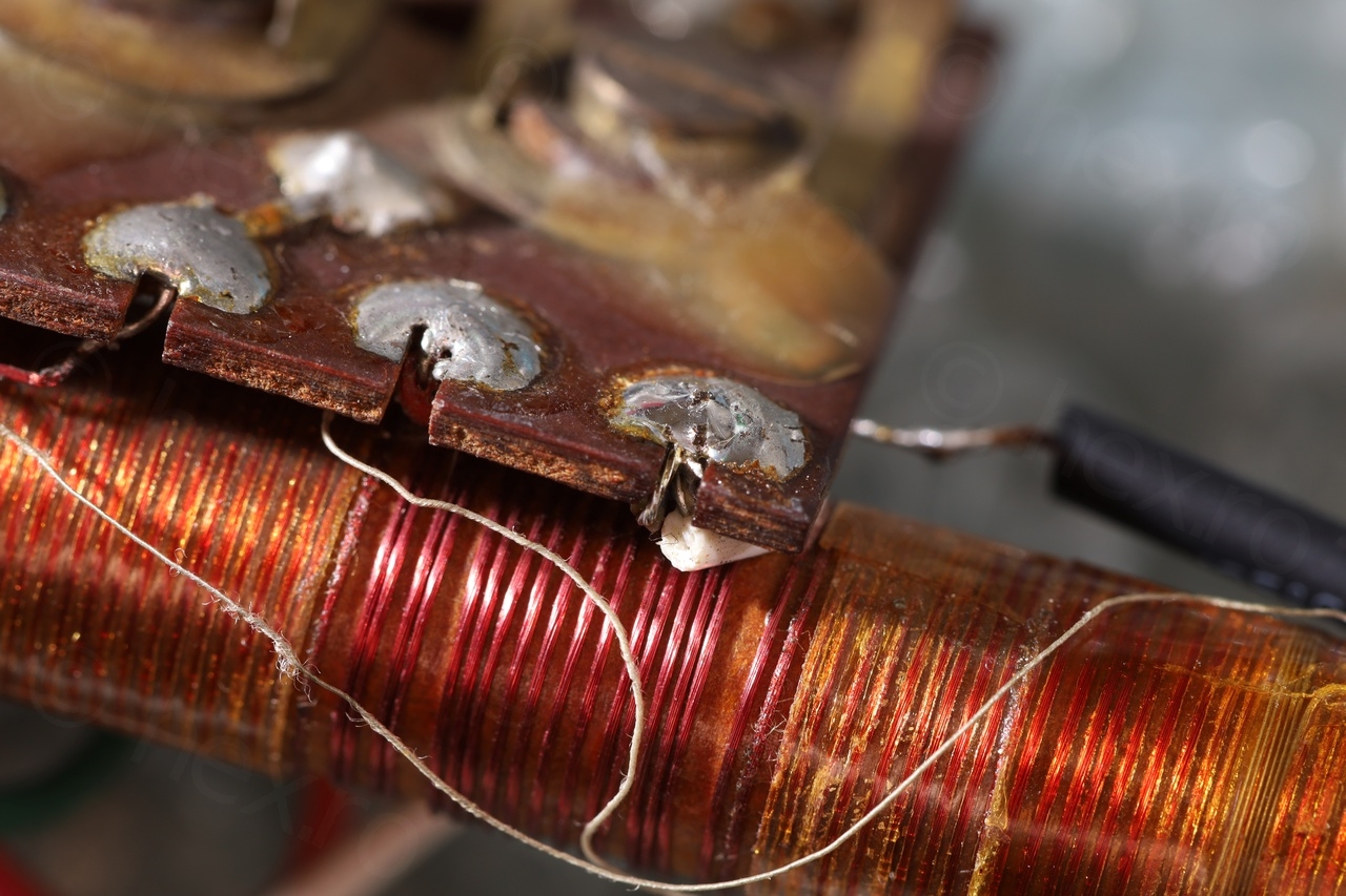
I first spotted that one Litz wire of the Ferrite Rod Antenna Coil was cut / snapped. It was still tinned so that means that the initial soldering was not securely done and it weakened with time / movements.
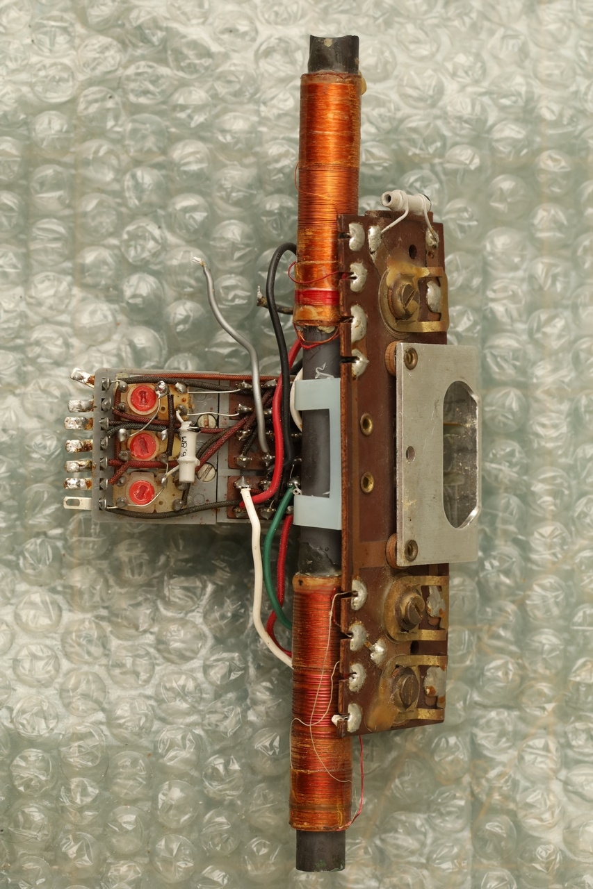
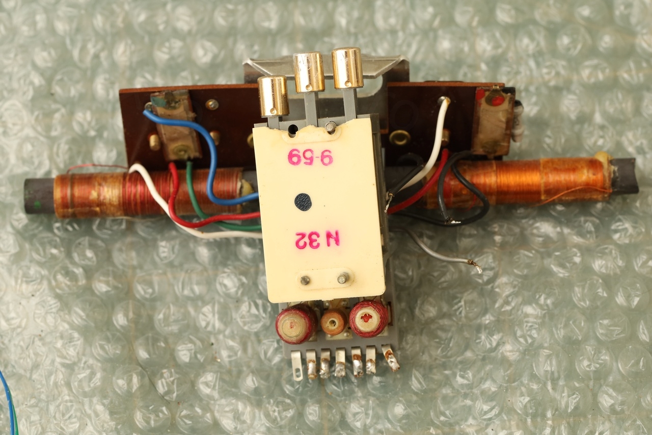
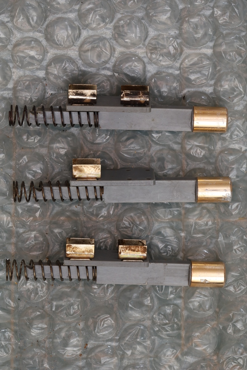
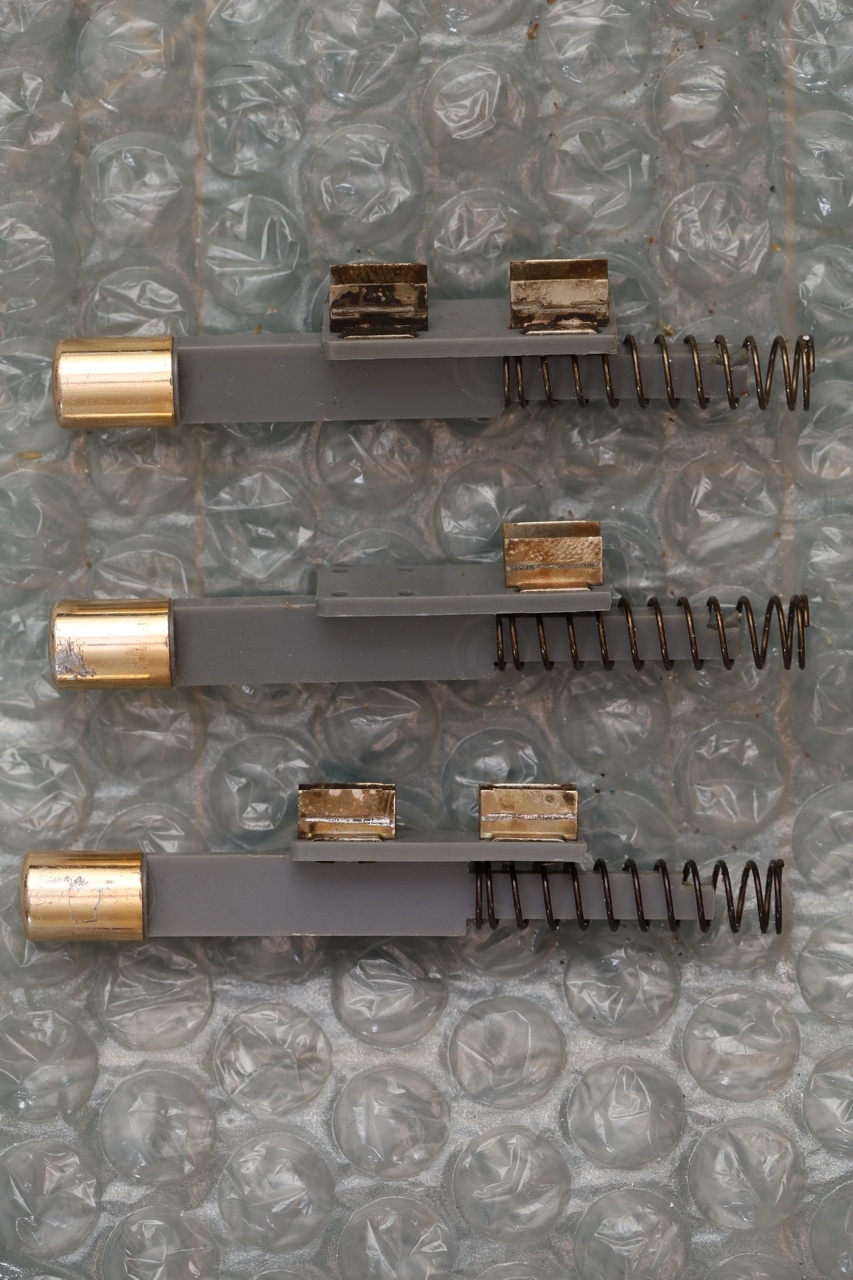
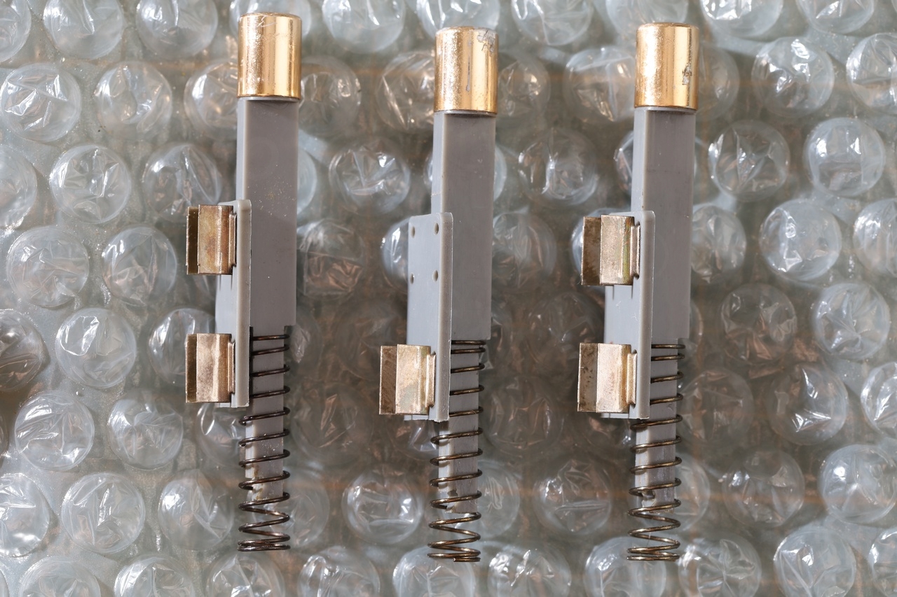
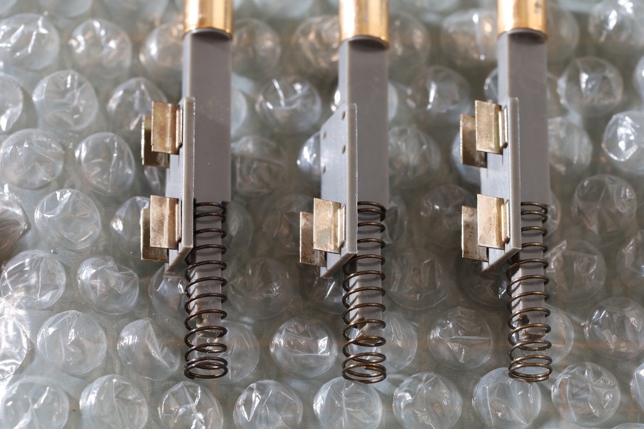
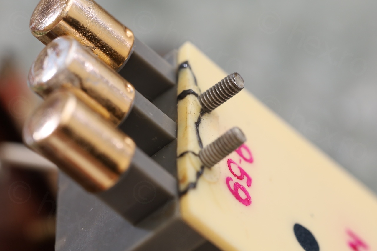
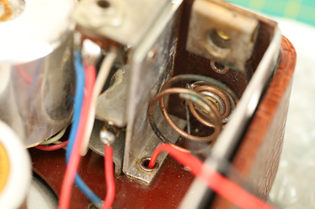
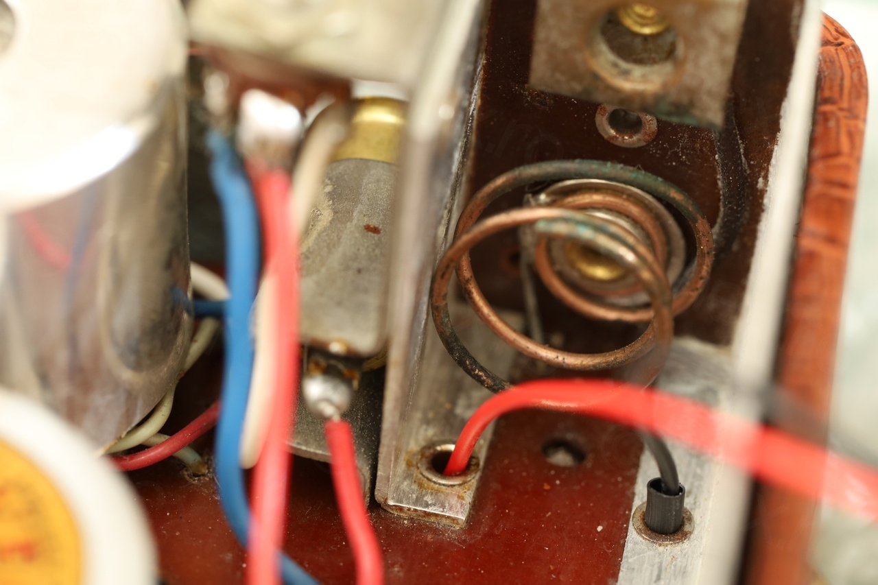
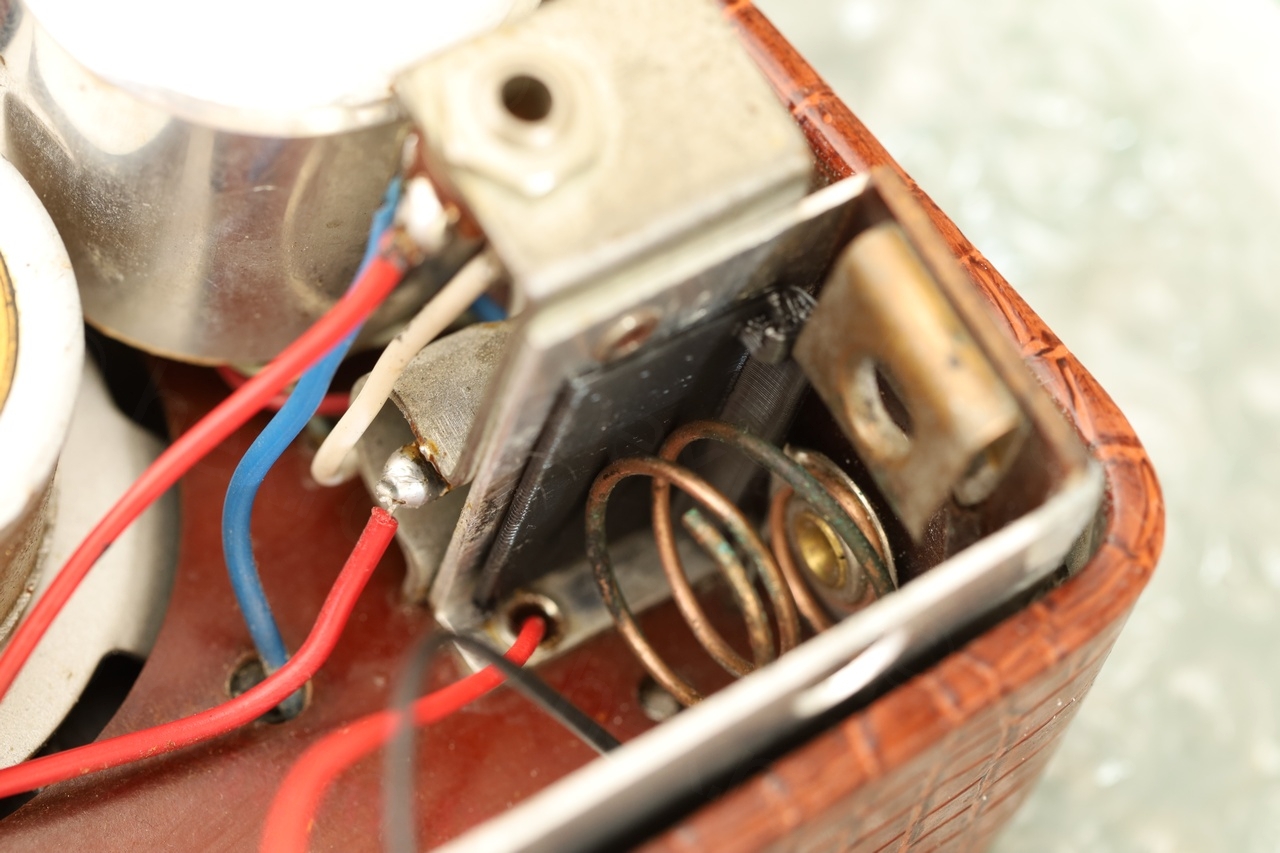
To get access to the wire, I had to take apart the whole “bloc d’accord” (not sure how to translate this in English). The Ferrite Rod Antenna alongside the interlock band switch buttons formed a unit in itself, like an entire block. To access the back side of the antenna and re-solder the broken Litz wire, the block had to be taken apart. It was too connected with many wires, for which I made a map.
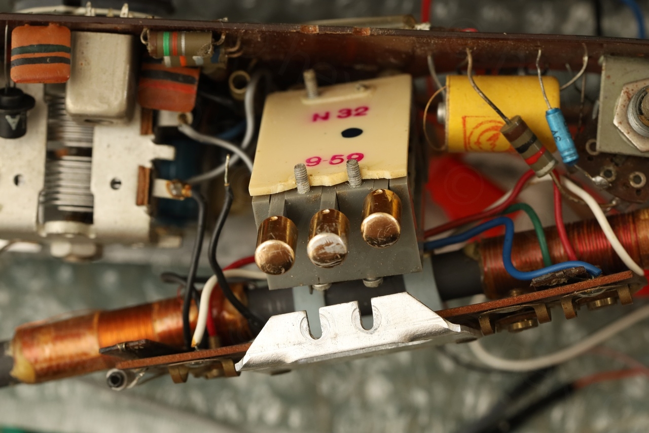
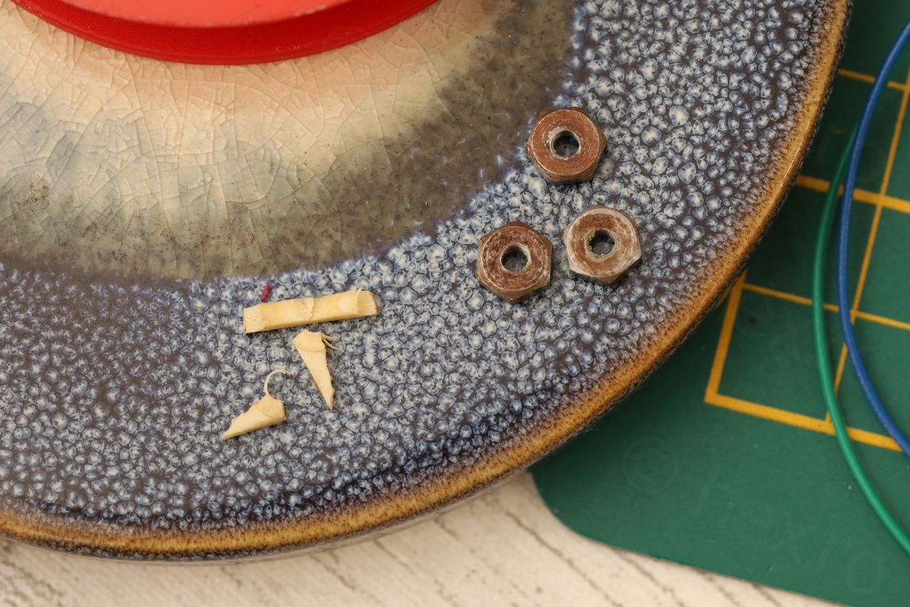
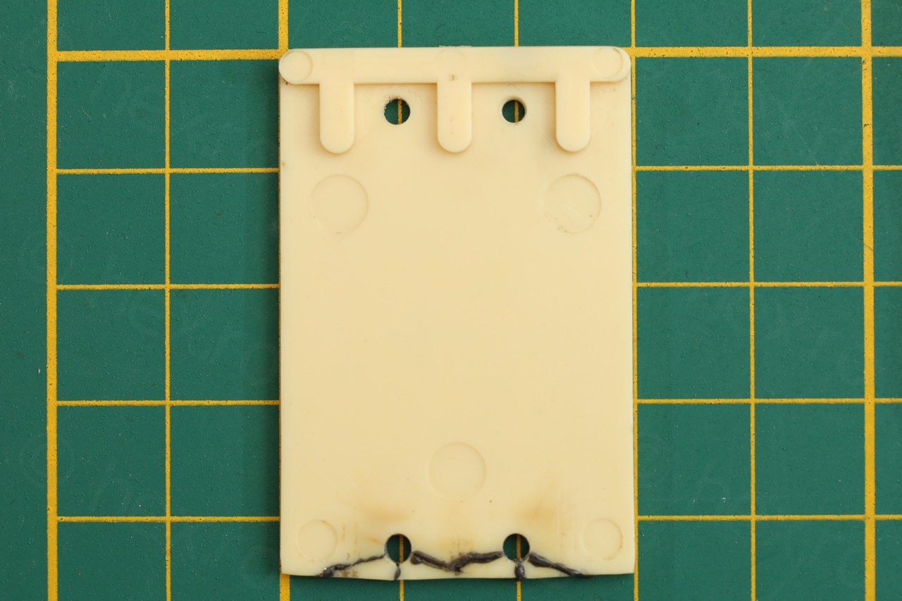
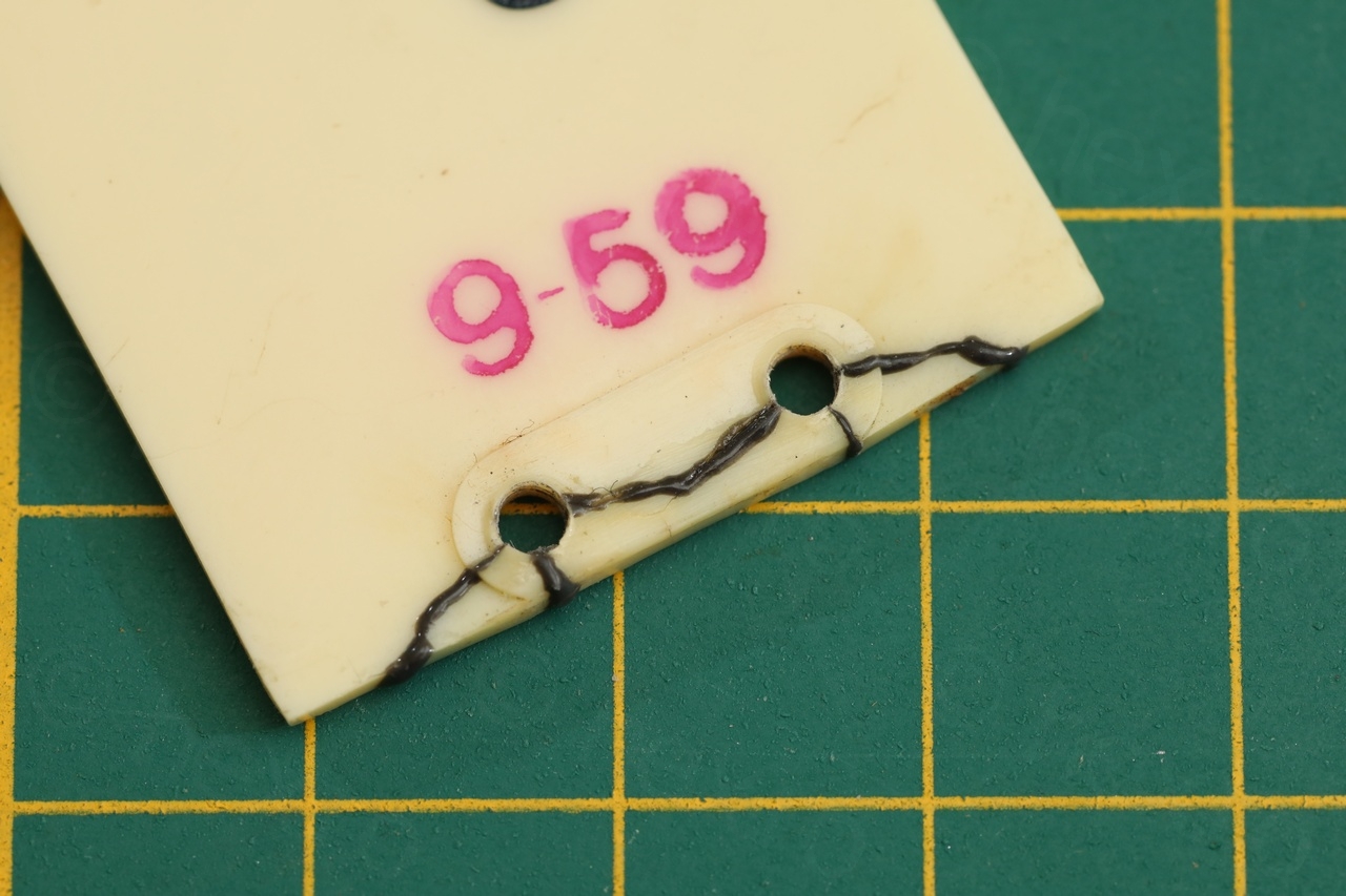
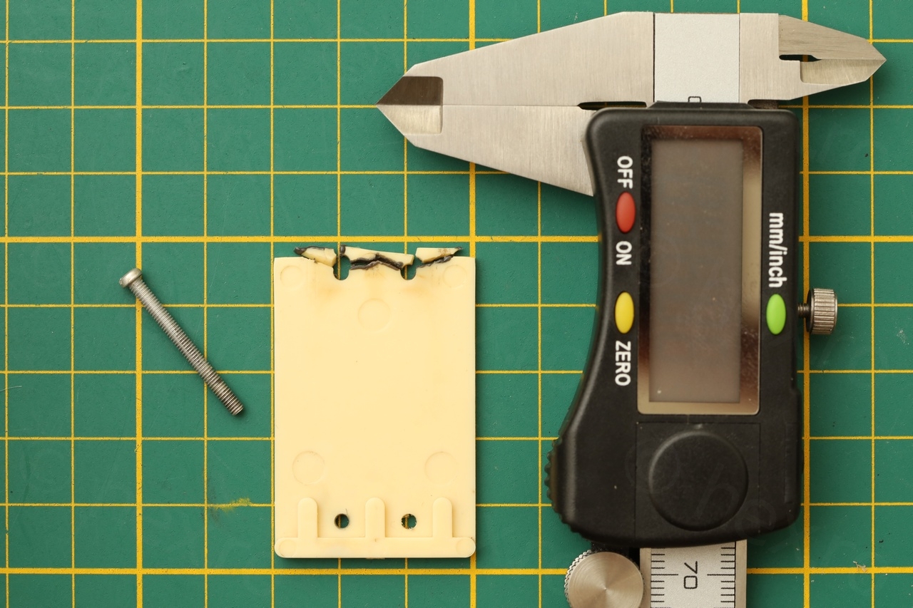
Working with this block was like opening a can of worms. First, its back cover (N32 9-59 beige plastic) was cracked – which would explain why sometimes the buttons would not latch. However, being screwed down, at least the plastic bits were not lost:
I first focused on re-attaching the Litz wire:

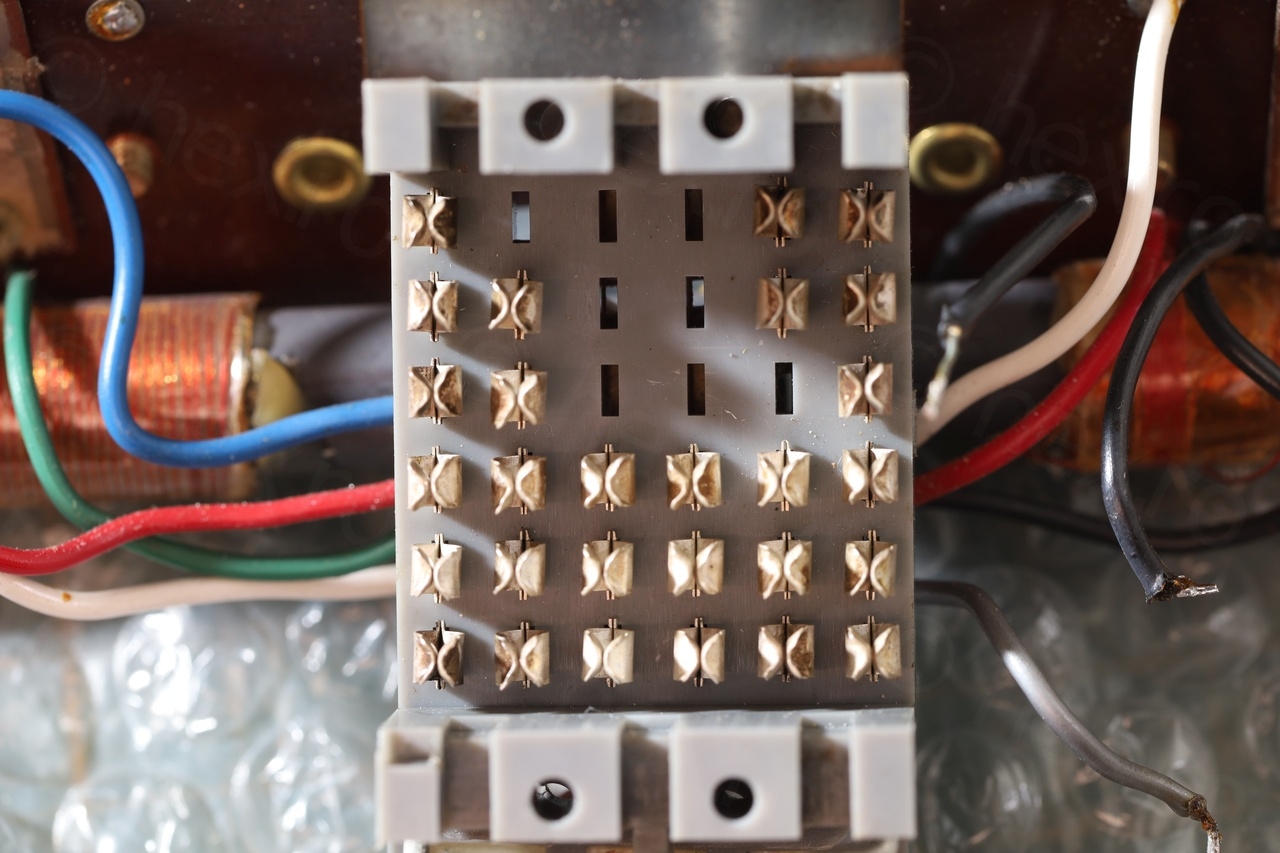
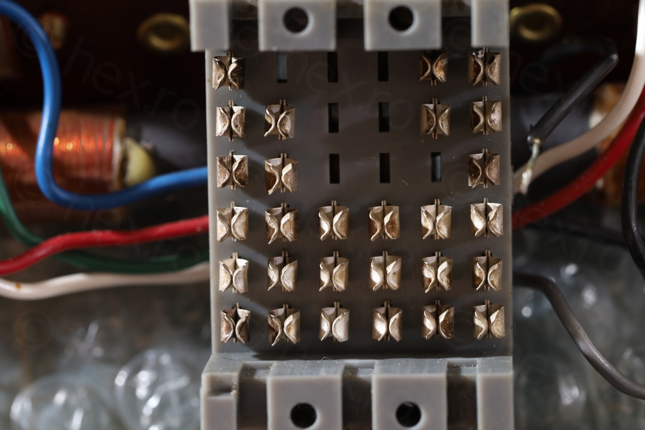
Second step, since plastic was cracked was to access the block switches and try to clean them:
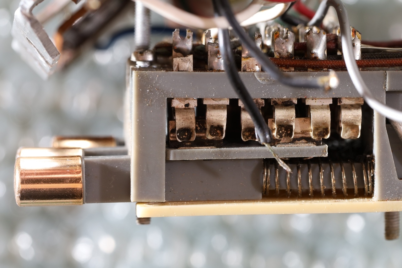
After some IPA / Contact cleaner, and using a thin cardboard filled with contact cleaner, things looked better:

The way the block is assembled, the cracked plastic cover is supposed to keep tension into the gray part (also plastic). With it cracked, the tension was weaker, which means that the inter-latch bar was a little loose. If one side button was pushed in, engaging the opposite button was sometimes not release the first one.
First attempt was to use JB Weld to try to glue the plastic together:


I first left the part to cure for 24h before trying to fit the screws through (since the gray part puts a lot of tension), it worked! It held properly. However, this only lasted until I had to apply the nuts to secure the block back into the radio. That was too much for the glue.
The only remaining solution was to …
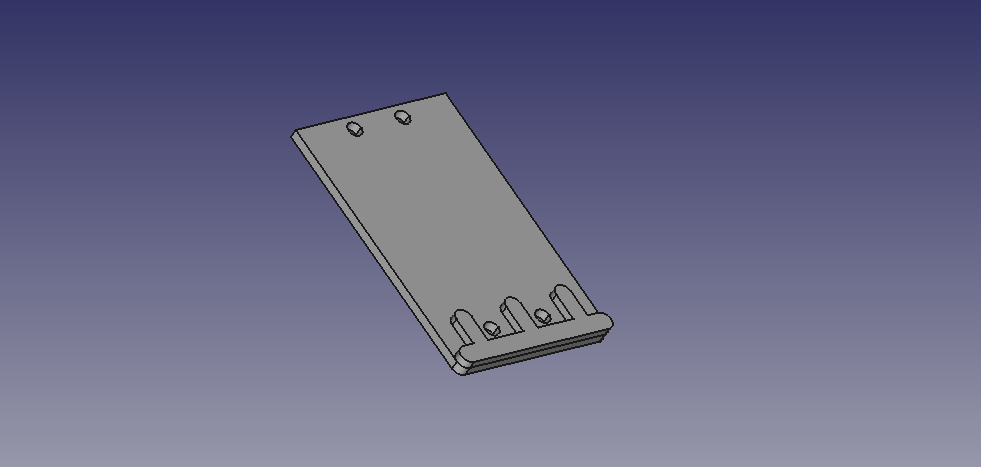
3D printing the cover of the interlock band switch
Went into FreeCAD and started designing. Since the back cover was already deformed, it took two iteration to get it right, since the holes for the screws are not aligned properly in the initial design, but I thought they were. I had to spread out the holes on the top a bit more.

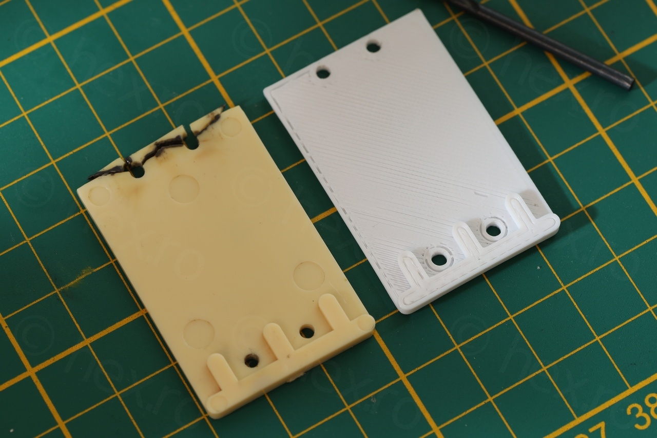
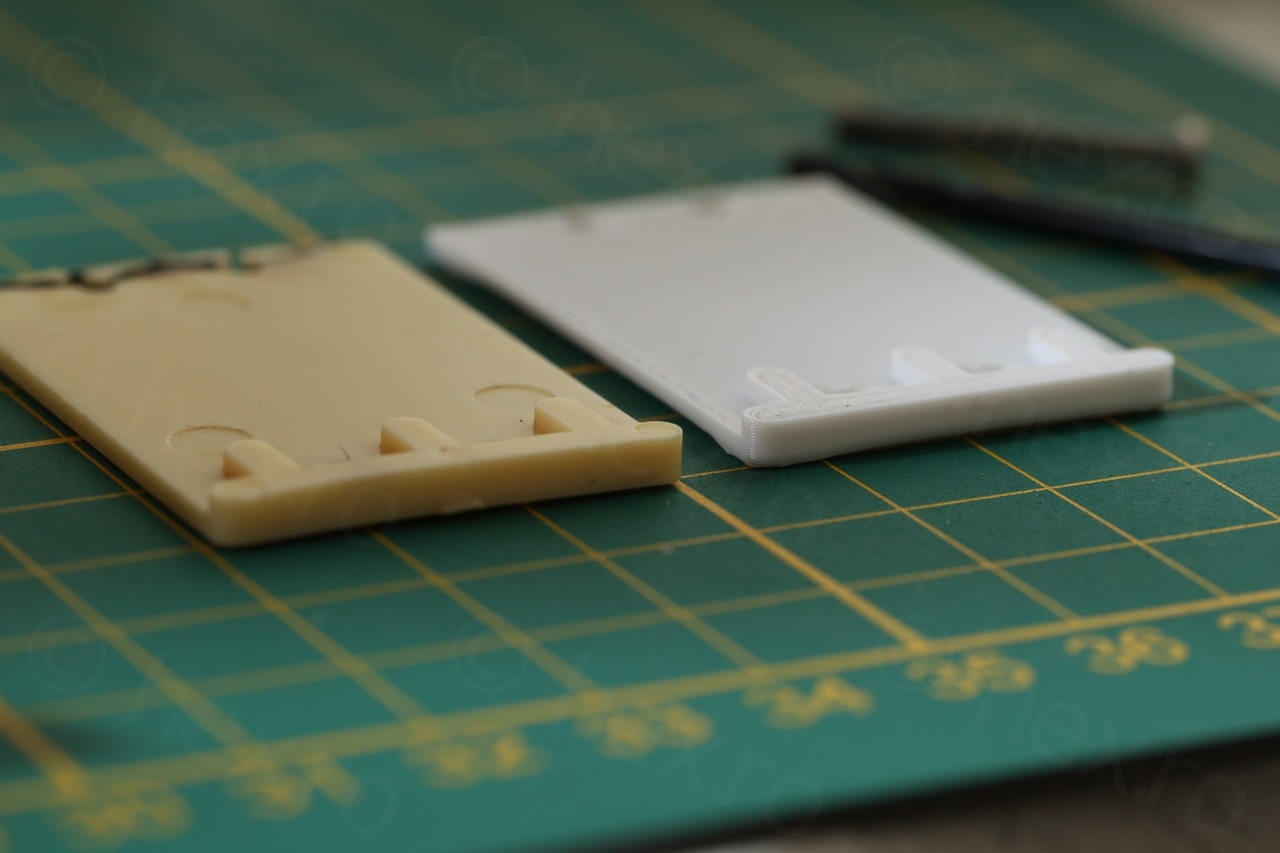
I didn’t have a Cream color filament, but since this part is resting against the circuit board, it won’t be seen. So I went with the White filament I had already on the printer.
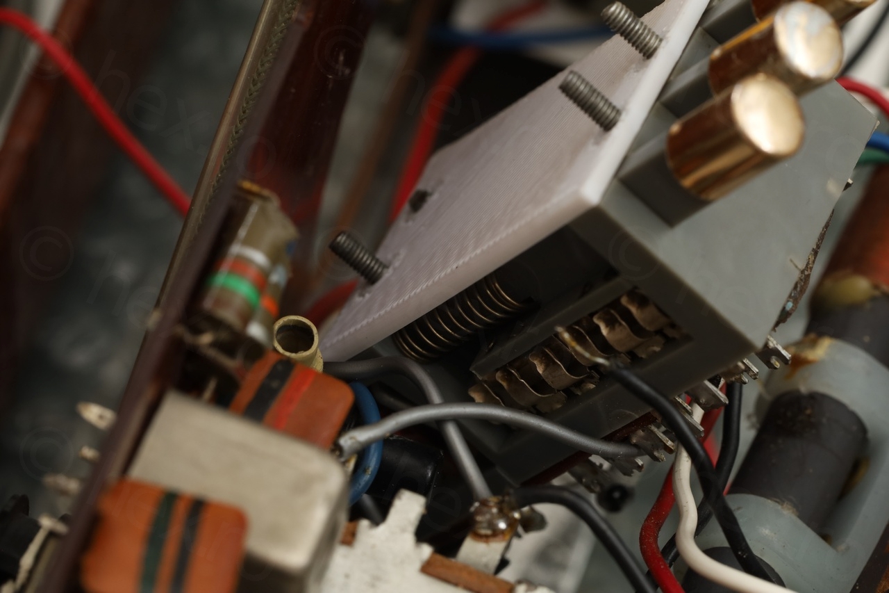
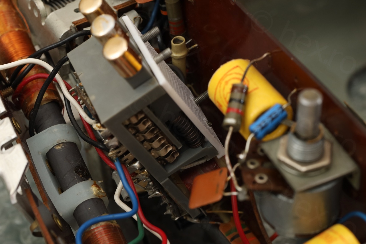
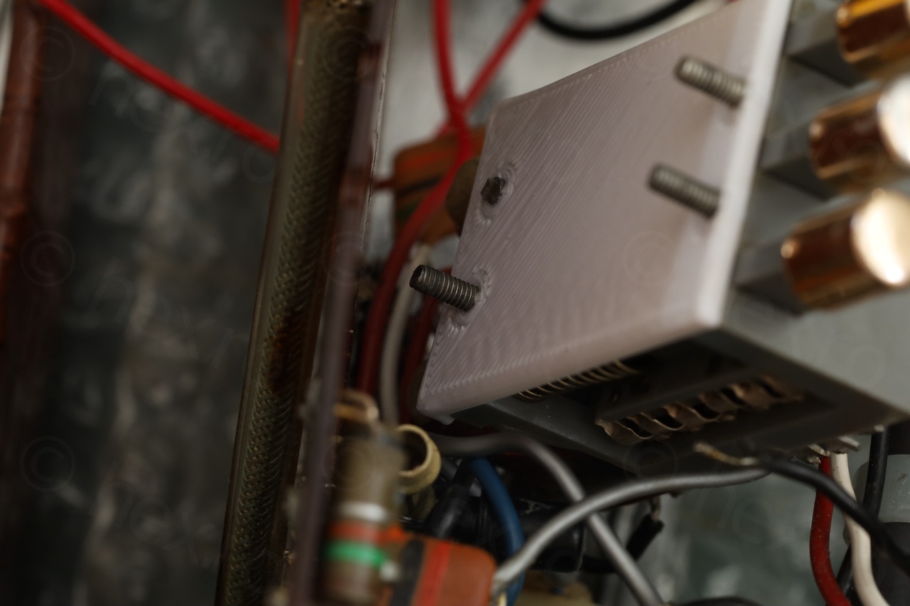
It turned out way better than expected. It holds perfectly to the tension applied by the gray plastic and the springs of each button. And no problems when I finally screwed the block back onto the circuit board, it did not crack like the glued stock one.
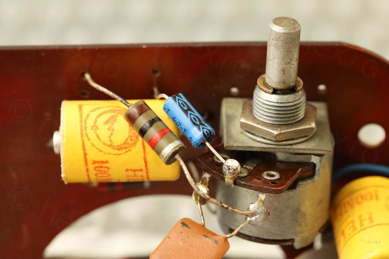
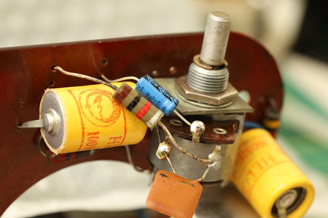
Just before reassembling the block there were two more things. The electrolytic capacitor (after the volume pot) was open too – and I could only access it if the block was out. And the Volume Potentiometer On/Off switch was faulty and needed to be taken apart.
Faulty On/Off switch of the Volume Potentiometer
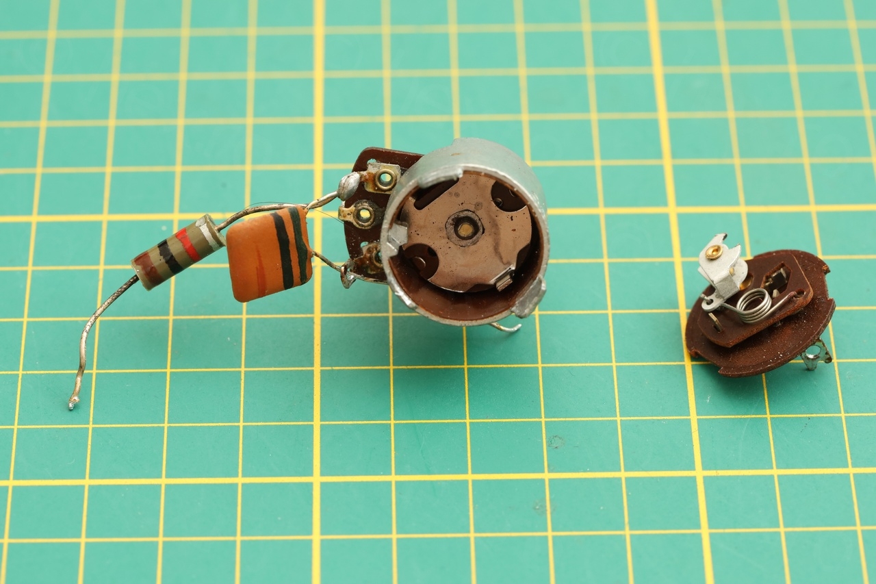
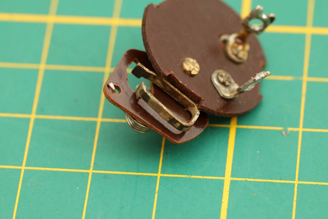
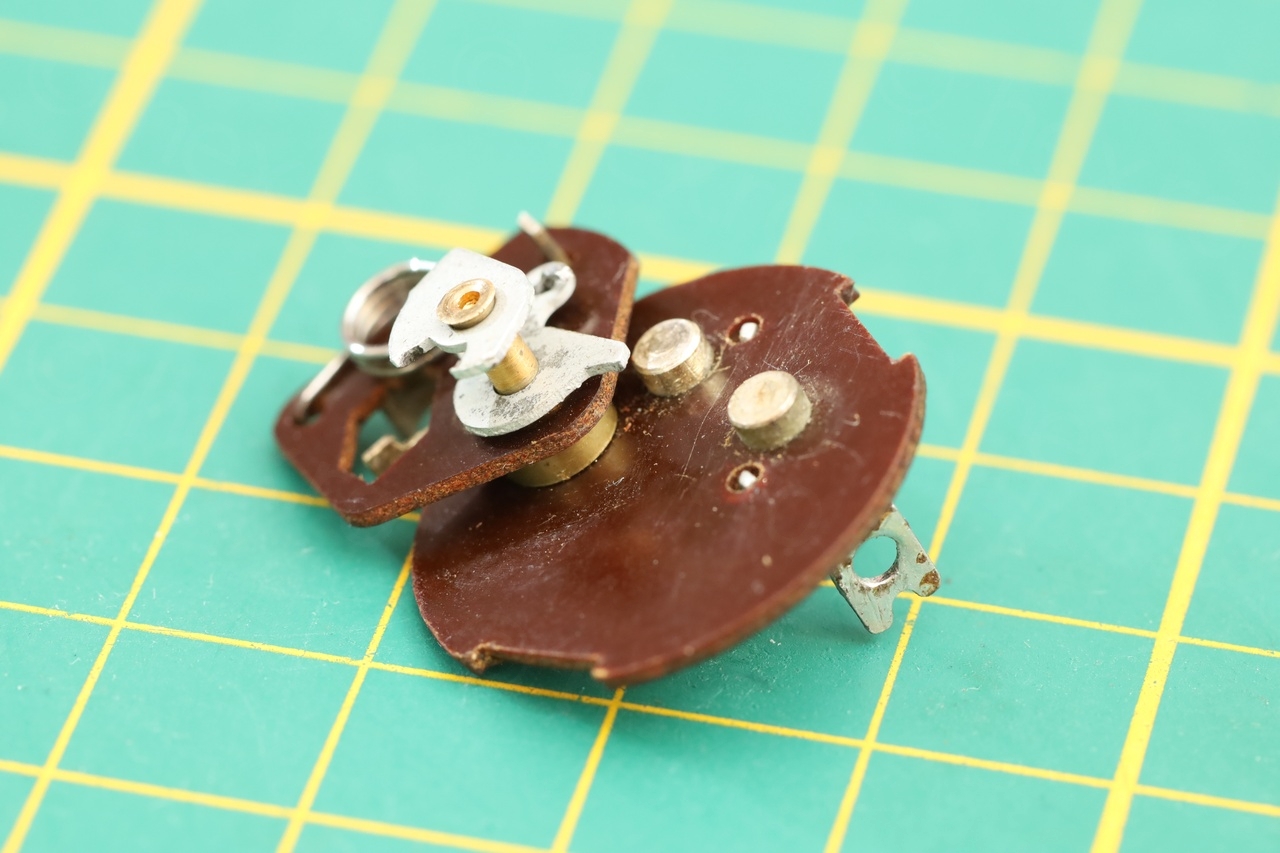
Taking apart the Volume Pot is easy, after de-soldering the wires and components that come to it. The On/Off switch was inside and thus the potentiometer needed to be taken apart too.
This turned out to create another problem, as the tabs gave up when trying to pry them open.
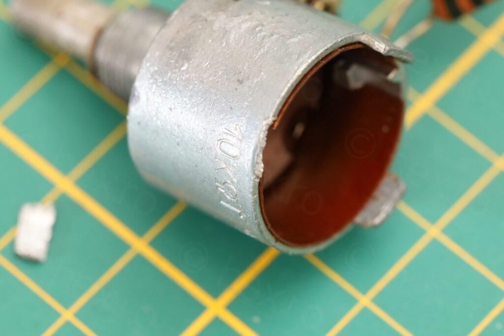
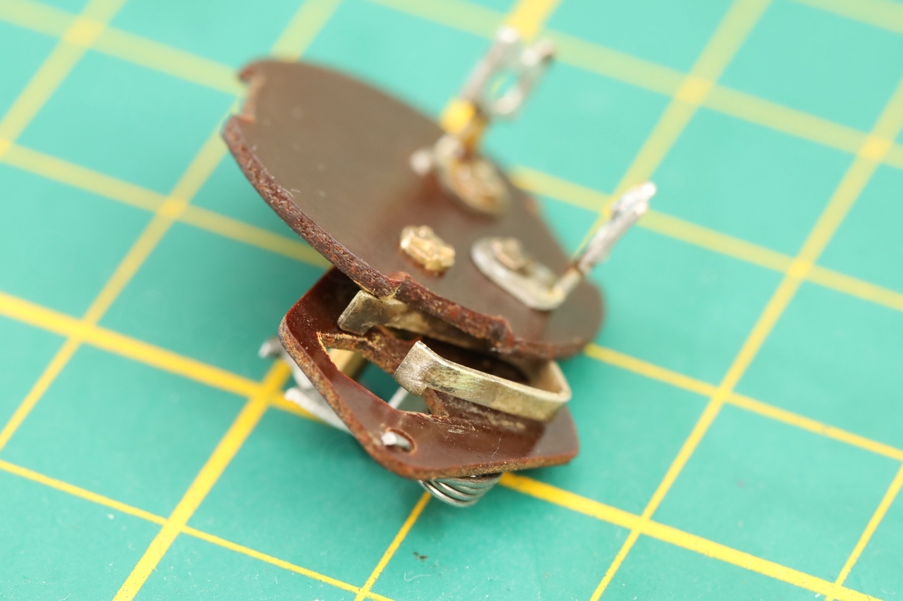
Inside of the pot everything was oxidized – no chance of ever letting the current pass through.
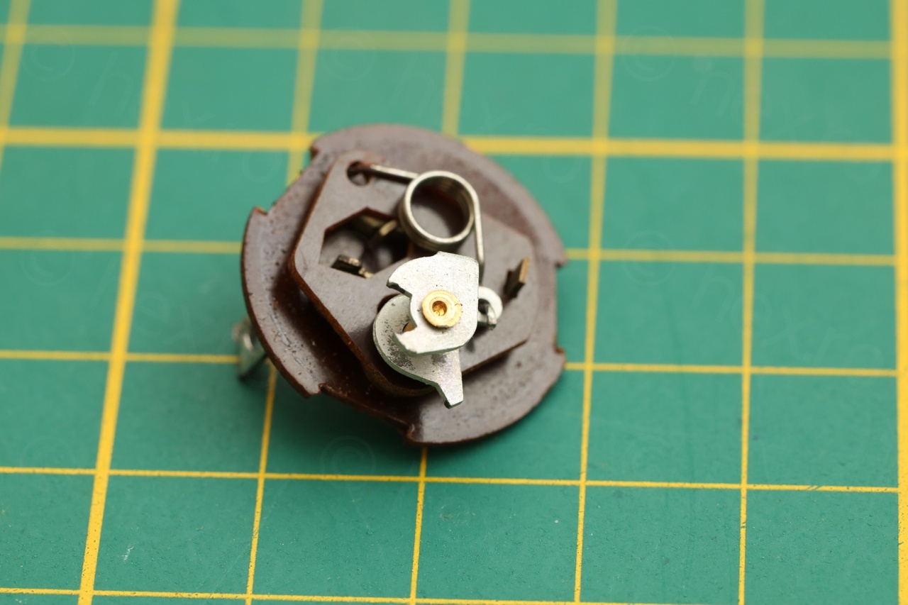

The fine steel wire was not enough to clean the oxidation, nor the contact cleaner. I had to also scrape away using an hobby knife. More contact cleaner afterwards in the hope that the fine layer of oil will slow down oxidation:

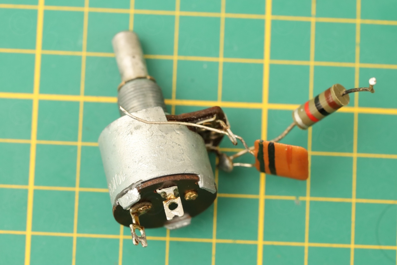
Rebuilding the Volume Potentiometer
Since one of the tabs gave up (and a second one seemed to have already started cracking) the only solution was to somehow glue everything back together. I used JB Weld to hold the tab into the slot (to keep the visual aspect). And to hold the back glued to the pot, transparent super glue.
This seems a reversible restoration – in the future, should the need arise to clean the pot again, the glues can be softened with heat – but they are strong enough to keep the pot together.
Faulty Electrolytic Capacitor
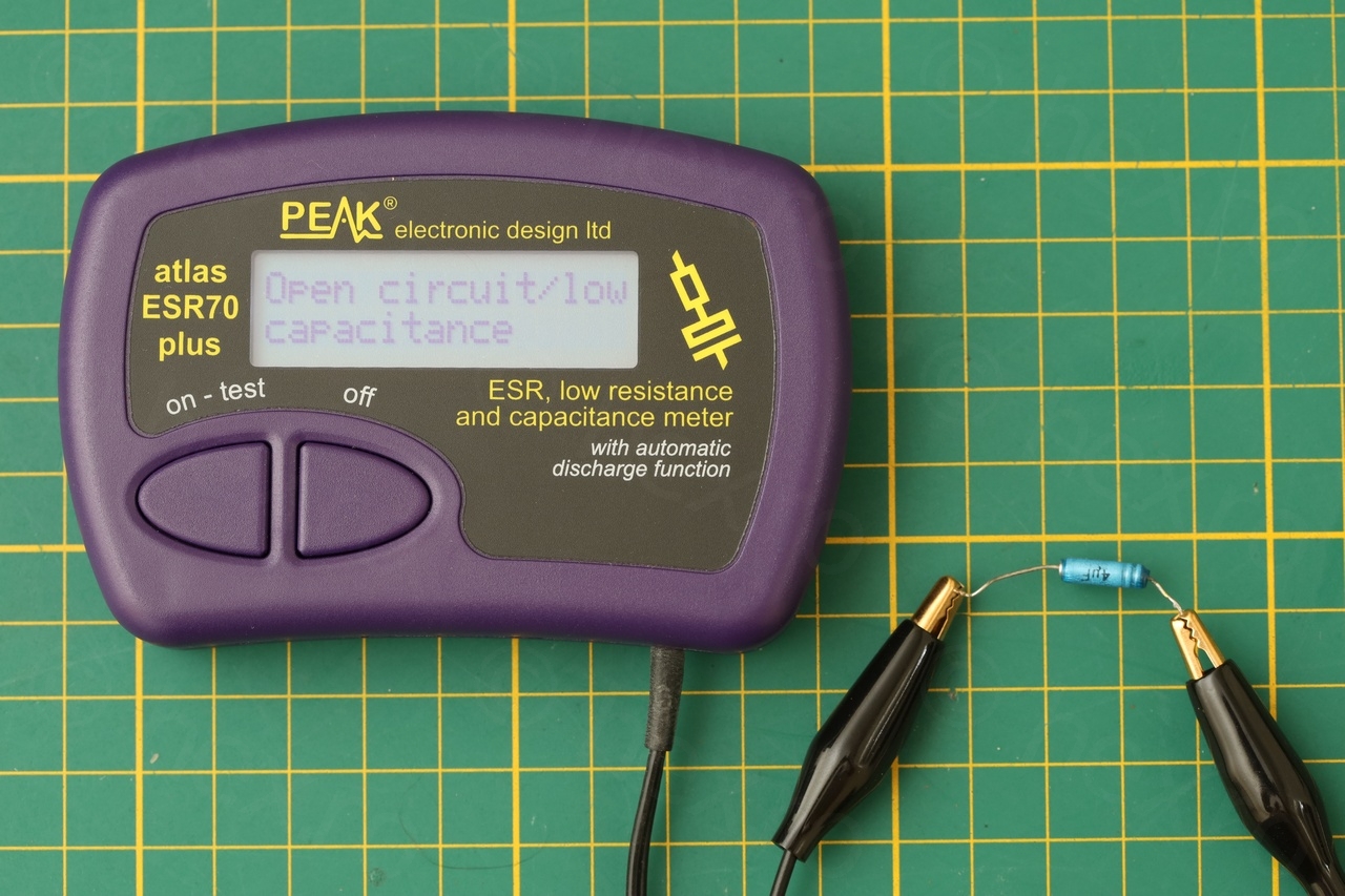
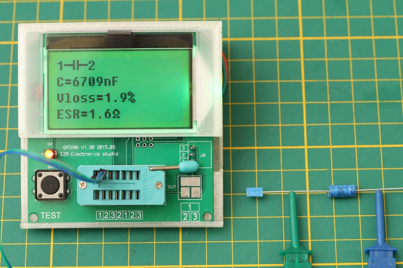
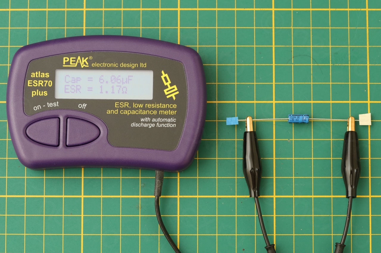
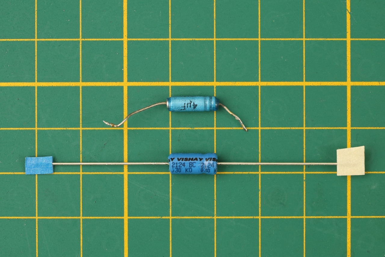
One of the reasons for the faint sound was the capacitor after the volume pot. I suspected it was dry and measured it as you can see below. The ESR70 Plus is showing it as open circuit. The GM328A is measuring it with 150Ω ESR.
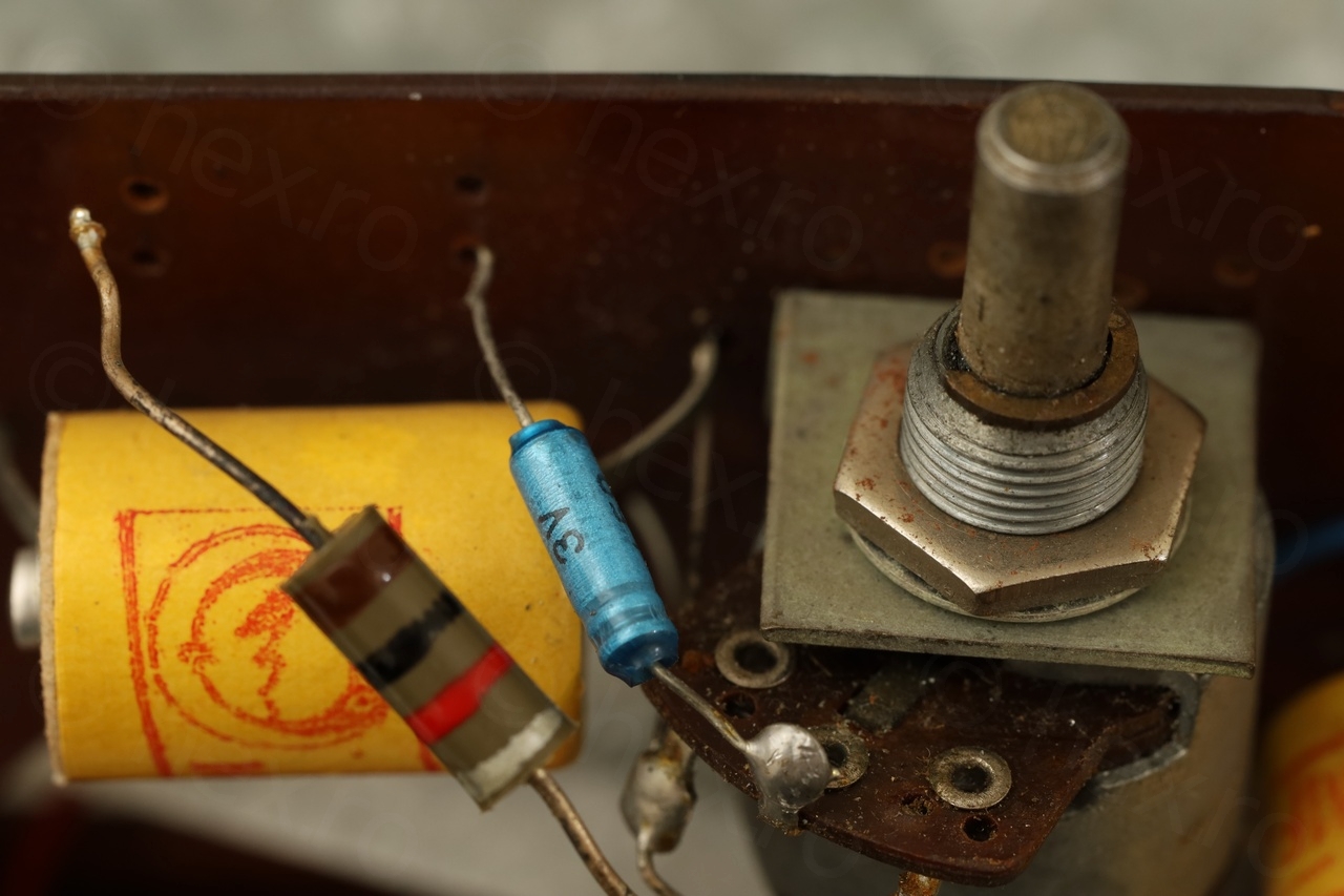

To keep the same visual aspect of the radio, I used a Vichay 4.7 µF / 63V (MAL203038478E3) capacitor. It measured just fine. Shape wise it was very similar to the original:
Final results:

I have checked the other capacitors (sometimes lifting one lead, sometimes paralleling a known good capacitor) and they were still acceptable. Thus, I decided to keep them in.
It was time to screw the inter-lock band switch block back onto the circuit board, but before that I took the chance to measure the RF amplifier transistor (T1) in circuit since its connections were still de-soldered. All was fine, high Beta:
After having cleaned up oxidation, 3D printing, fixing broken Litz wires, capacitor replacement, etc, the “stack pointer” was finally back to continue the sensitivity diagnosis. As radio still had zero sensitivity …
Diagnosing faulty T3 (SFT107) transistor
I noticed that radio was loud after Power On and for a brief moment, but then it became quiet:
I didn’t know if there’s anything wrong with the AVC circuit. I have lifted the leg of the AVC capacitor (measured fine), of the detector diode feeding the AVC circuit (measured fine), measured the resistors… but I could not find anything wrong on the path of the AVC.
I measured again the voltages (bottom part of the page below):
It kept bothering me why the collector voltage of Tif(mid) which is the T3 – had such a low Collector voltage. According to the Babycapte schematic, it should have been around 4V, but I was measuring less than 1V. There was nothing around it that could cause such a drop in voltage, after measuring all the components around it.
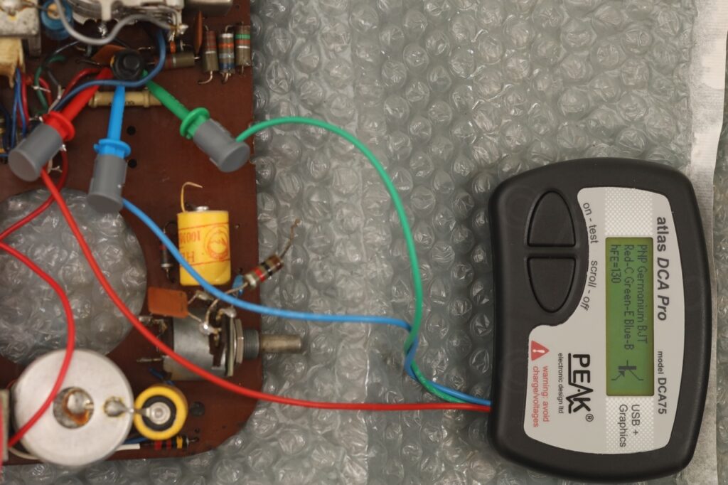
And with the AVC components partially lifted, I decided to attempt to measure the T3 transistor … and surprise, Beta = 1! And a diode between CE pins ?! What ?
It was time to take it out of the circuit and measure it properly – but the results were flaky. Sometimes it was measuring as a Diode, sometimes as a Transistor with low Beta (19-22).

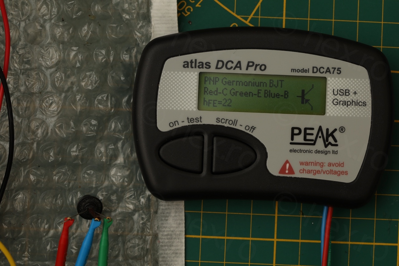

Something was definitively fishy with this transistor. According to datasheets I found online, the Beta of the SFT107 should be between 26 and 120, so 19-22 was a little too low. But not low enough … OR MAYBE there was something fishy going on inside the transistor ? And measured very low while still soldered in – but the excess heat (or lead bending while de-soldering) made it behave a little better ?
I tried to do a resistance measure between the Collector and Emitter of the germanium transistor and the resistance was low on one direction. This may be expected for Germanium transistors but it still didn’t feel right.
I decided to swap it. On another identical radio schematic (thanks now to tsf-radio.org), the same schematic has a different set of transistors:
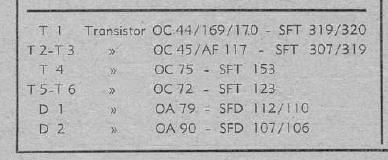
Since I had some SFT307 (it does not have the dot, I think it may be Bulgarian made) I decided to use one of these transistors as a replacement.

The NOS transistor didn’t have a much higher beta (if I remember well, 31) but it was amplifying better. Just after power on the hiss was much louder. It still was decreasing in volume very very quickly after though …
Diagnosing faulty T2 (SFT108) transistor (oscillator / mixer)
The last transistor with incorrect Collector voltage was the local oscillator / mixer, T2, which is model SFT108.
I decided to measure it and it exhibited the same behavior as T3, even smaller resistance between Collector and Emitter and also low Beta. For this one I close an OC45 (that I ordered from a local Brussels shop, Electols / Halfin).
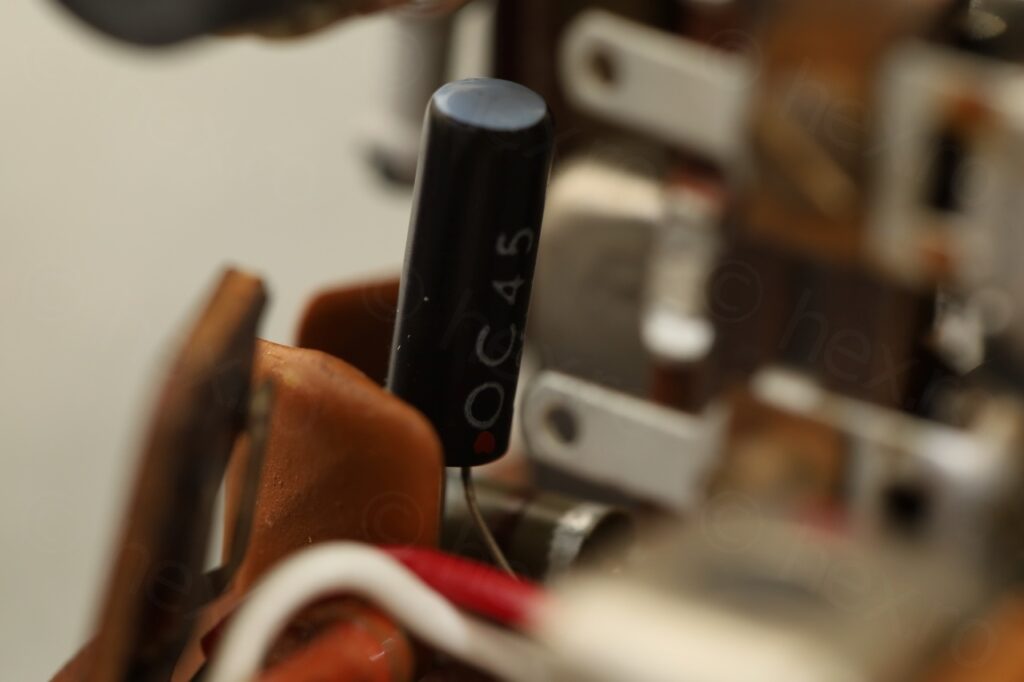
And all of the sudden the radio became alive 🙂
Reattaching the front grill
The front grill of the radio was a little dirty and I also wanted to have a look at the speaker itself. Discovered that I could pry off the front grill from a corner – it was lifting very easily. However, just after slight lift-off – I realized that I have to break it off.
It had some plastic pins that were going through the front case of the radio and the manufacturer decided to just melt the ends on the inside. Since I could not clean it in place out of risk of damaging the loudspeaker, I had to pry it off and then, figure out how to attach it back without ruing the front plastic (without gluing it back).
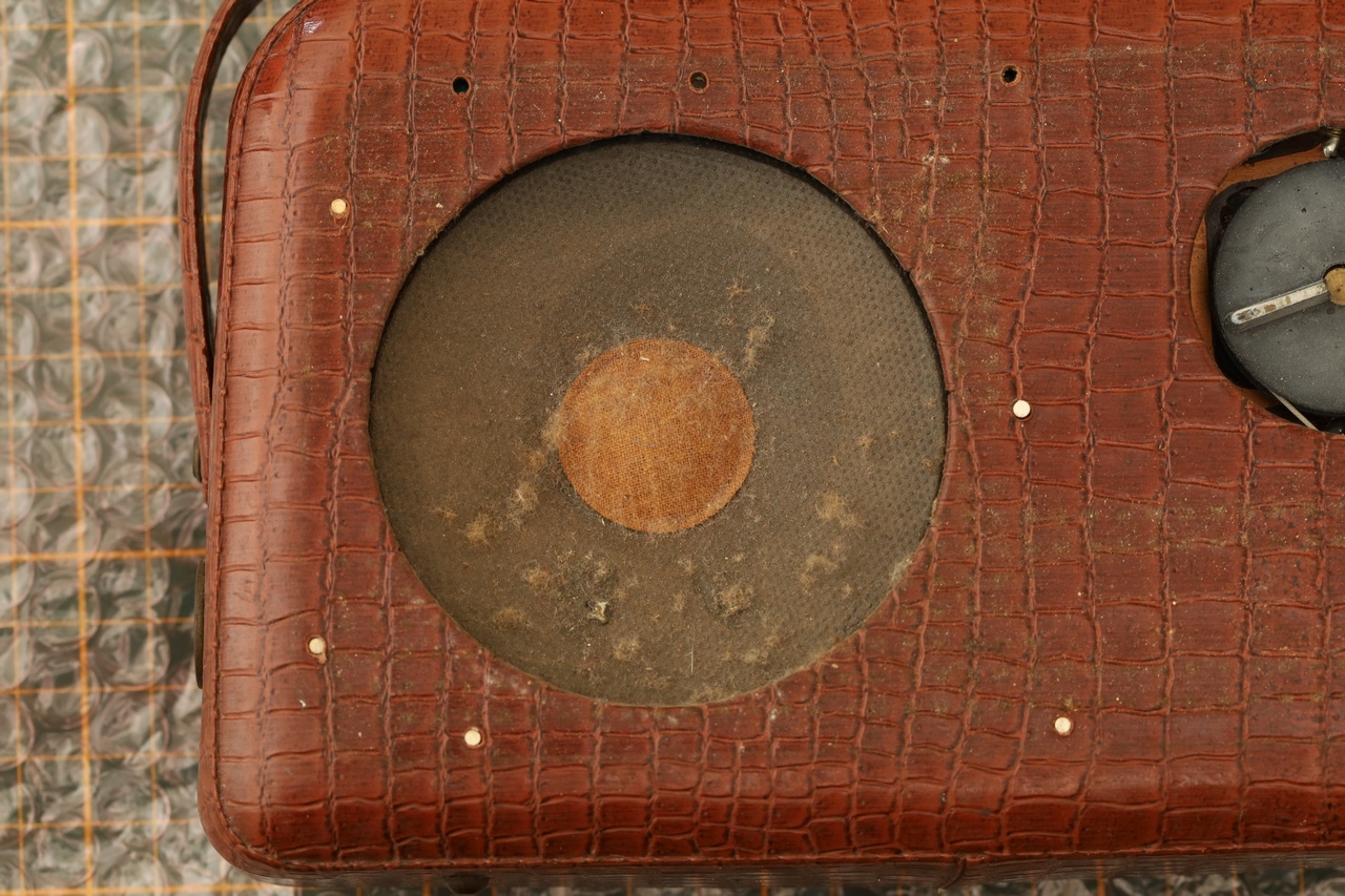
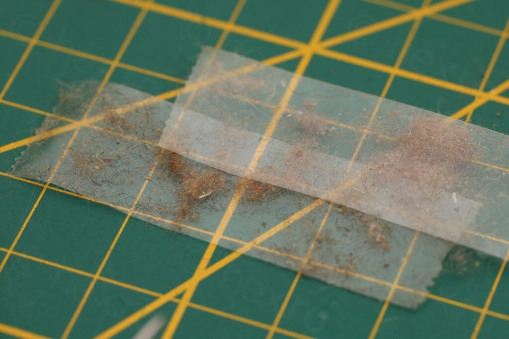
I cleaned the dust with a scotch tape (I didn’t want to rub it in more):
and also cleaned the plastic behind the front grill with a wet towel.
To reattach it, one choice was to glue it directly back onto the face of the radio. But I didn’t feel like messing up the front of the radio. I mean, once mistake (sliding it off) or something else, and then there will be glue visible.
I decided to 3D print some plastic tabs (2mm wide) that could slid in from the other side, after having a little glue added to them. They would stick both to the front grill as well as to the existing holes, while the radio was facing down:

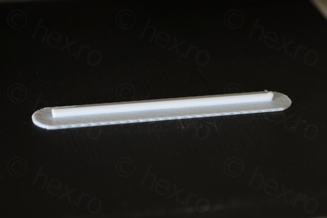

Procedure was to apply a bit of glue on the end of the plastic, slide it through until it was touching the front grill, then glue a bit on the back. Results are perfect.
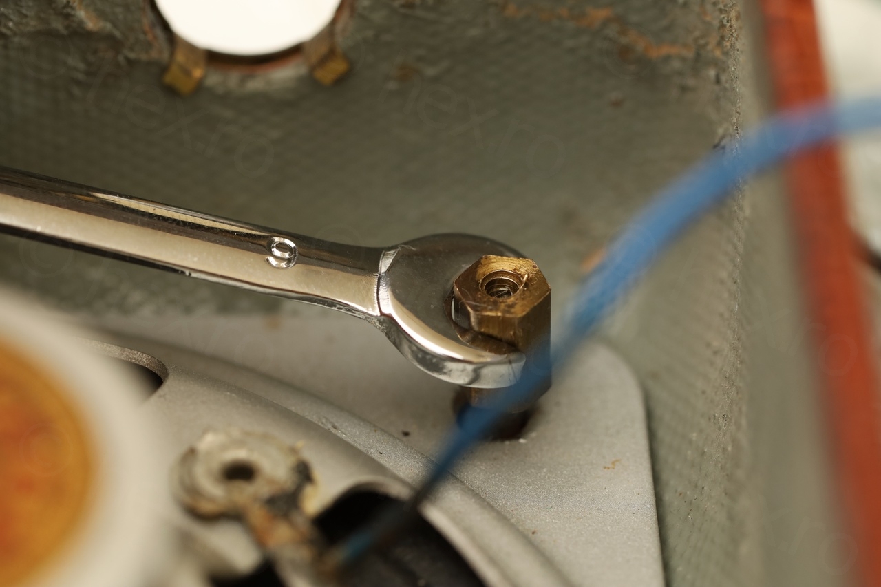
Another problem that was encountered was that the loudspeaker had to be removed, to access the few pass-through holes for the plastics. Some of these plastic tabs were covered by the speaker metal support which thus had to also come off. But the standoffs for the speaker were rusty – too much force would probably dislodge the standoffs from from the radio case.
With some heat and oil later – I was able to unscrew the two standoffs without breaking bond to the radio case:

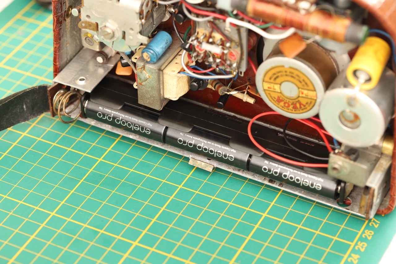
Fitting a new battery holder for AA batteries
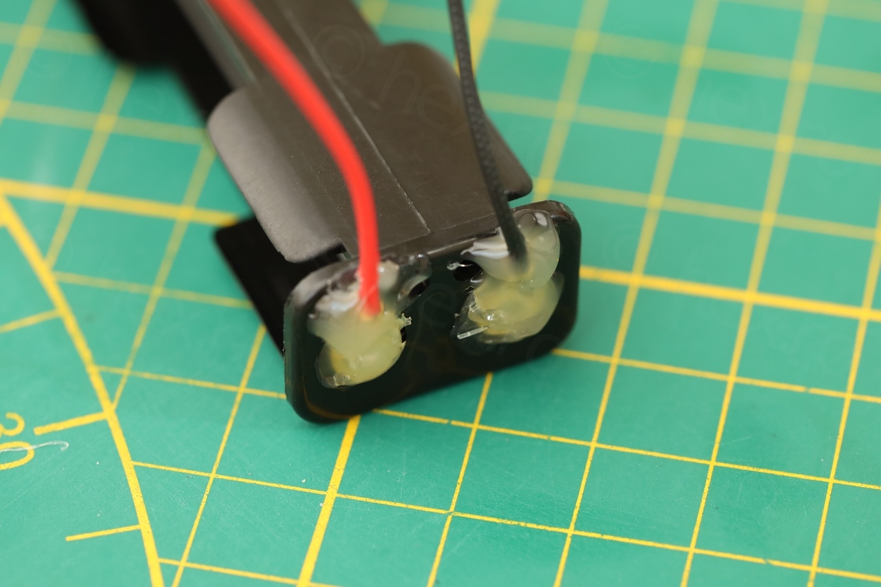
This radio had place for 6 x 1.5V batteries that were wider and longer than what is currently available on the market. To make it really portable, I had to retrofit a modern battery holder in the same available space. While trying to make sure that the metal bits don’t end up short circuiting anything. And while providing a guard for the Battery “-” wire so that in case it rubs with the case, at least it won’t short circuit either.
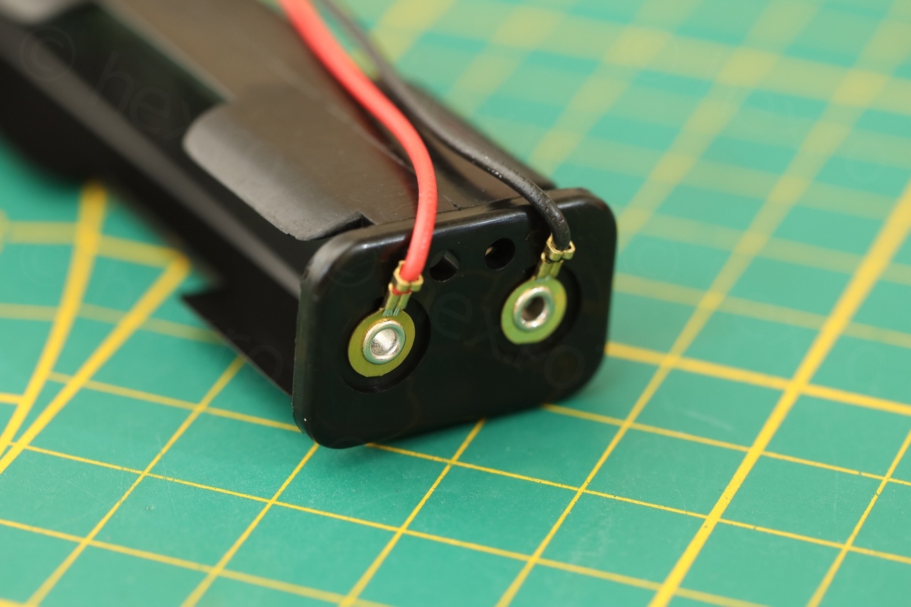
I was able to order some 6xAA battery holders that are 3 batteries long and 2 batteries wide:
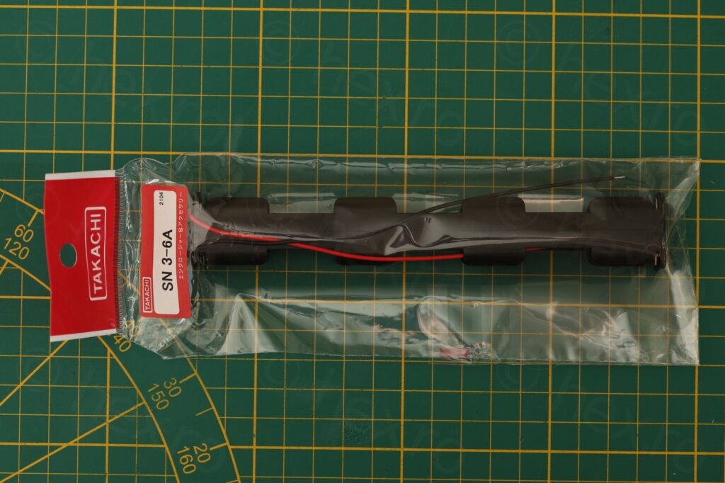
This fitted perfectly, but there was exposed metal on both ends of the holder that could touch existing springs (which I preserved also):
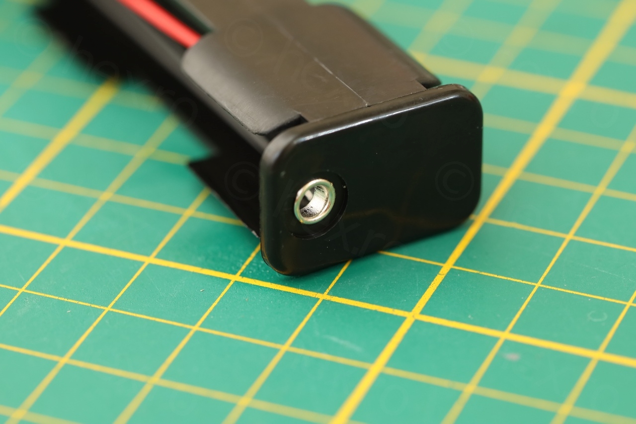
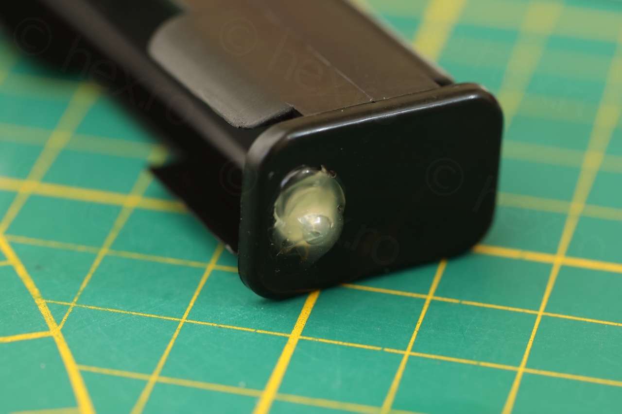
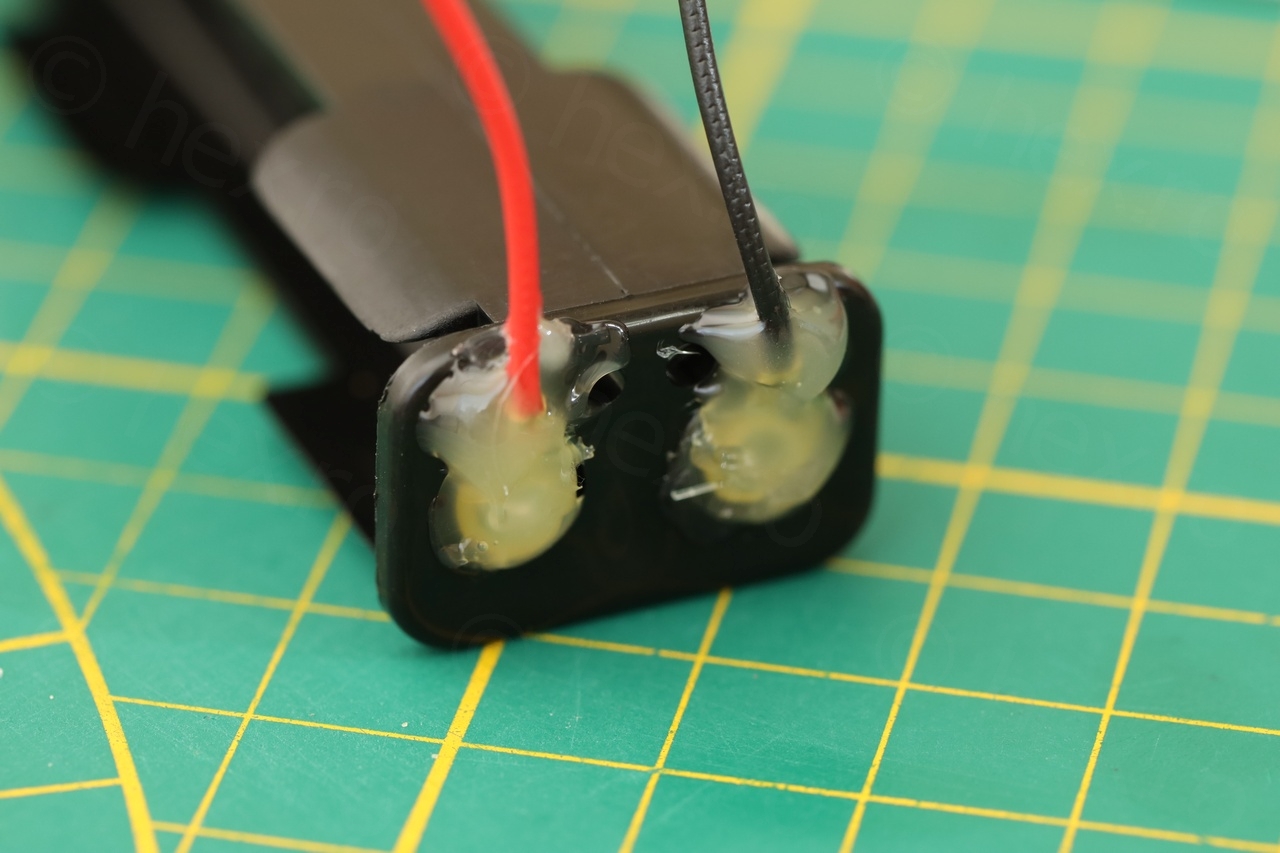
I decided to use some hot melt glue to cover these parts – and thus minimizing the risk of them touching other metallic parts in the radio and causing short-circuit:
The next step was deciding where to attach the new leads, as to not destroy too much the look of the radio. I spotted some holes where the existing battery holder was attached to the circuit board. This way the new leads will not be soldered on the visible part, but behind on the circuit board.

I payed attention of course to wire the Battery “-” to the On/Off switch on the correct side. And since the Battery “-” passes through a hole in the metallic part that is connected to Battery “+”, I decided to also insert a shrink-wrap tubing to prevent the new wire from rubbing into and touching the existing metal.
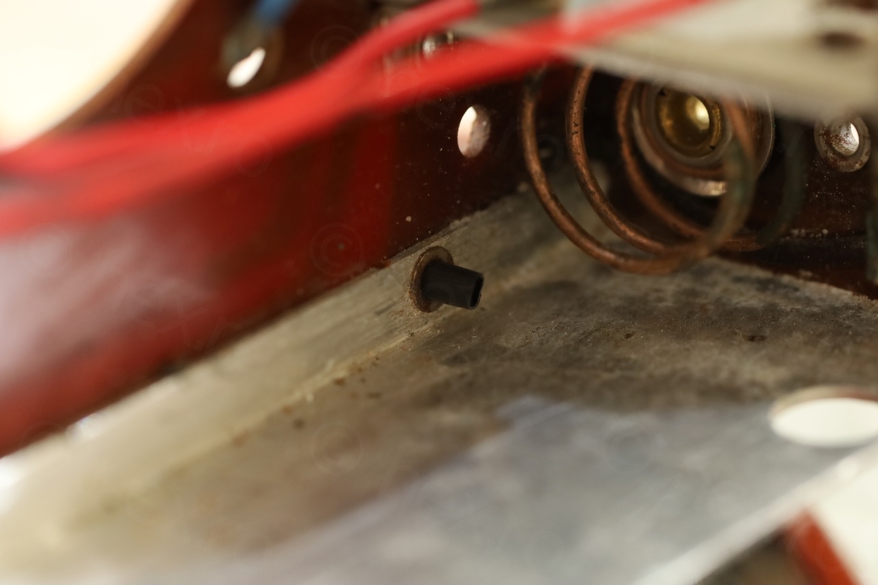
One last problem was that the old existing spring was very close to the housing / metal and causing a short with the pressure from the battery holder:
While I could try to bend it away from the housing – I decided to use a 3D print spacer:

The results are good:

Unsolved issues
There are two / three problems that I decided not to tackle, and I’ll give the reason below.
While measuring the voltages after I got the radio working (bottom part of the page) …
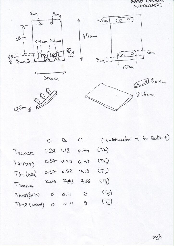
… the T4 transistor voltages (SFT103) are a little off. The Base voltage should be around 1V, but it is 2V, and Collector should be closer to 8V, but it sits lower at 7.6V. I think the Germanium transistor also started to degrade (like the other two). However, it still drives and is plenty loud – thus, I decided to leave it in. As alternatives for the SFT103, the schematics above suggest OC75/SFT153. Also, Transistor Equivalents (11ed) suggests AC126 / 2N2429. So there are few choices still available, thus, no rush in replacing it for now.
One other thing that I decided to keep was the existing tuning thread. It became a little loose and sometimes it slips. In specific areas, there is a need for a little down pressure on the tuning knob. I didn’t find it very annoying, thus, I chose to keep the original.
And the last thing that I did not tackle is that here seems to be a some crackling from the tuning capacitor in a specific position. I chose not to mess with the capacitor, reason is that is not stopping the radio from working and is not permanent.
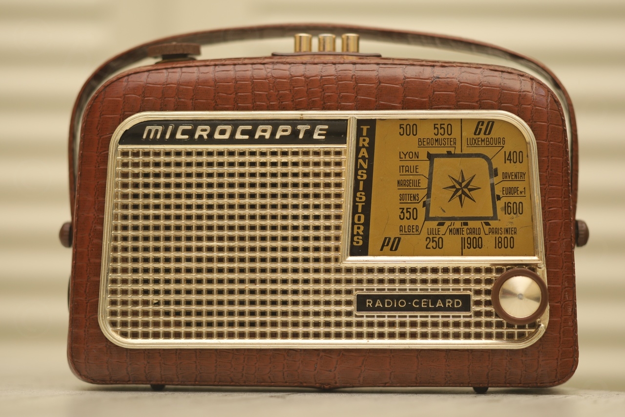
Photos
Finally, some photos of the radio – it was indeed a tedious restoration, with rabbit holes filled with rabbit holes filled with …, but in the end it works and it looks nice.


Leave a Reply