

The flea market is a harsh environment. Not buying the one thing you are tempted by implies leaving it to the elements; or to the handlers that throw the boxes in and out of the trucks; or to countless fingers that touch, move, pull, poke, throw it around, throw other things on it, etc.
Thus, I decided to rescue this little radio that looked clean.
Table of Contents
Overview
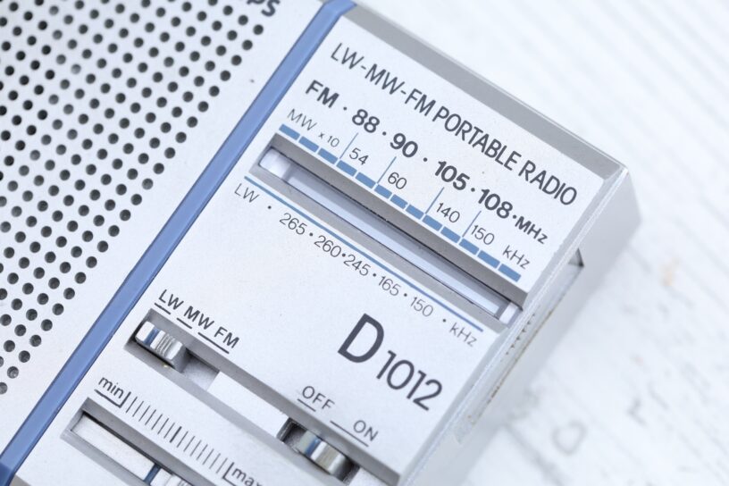
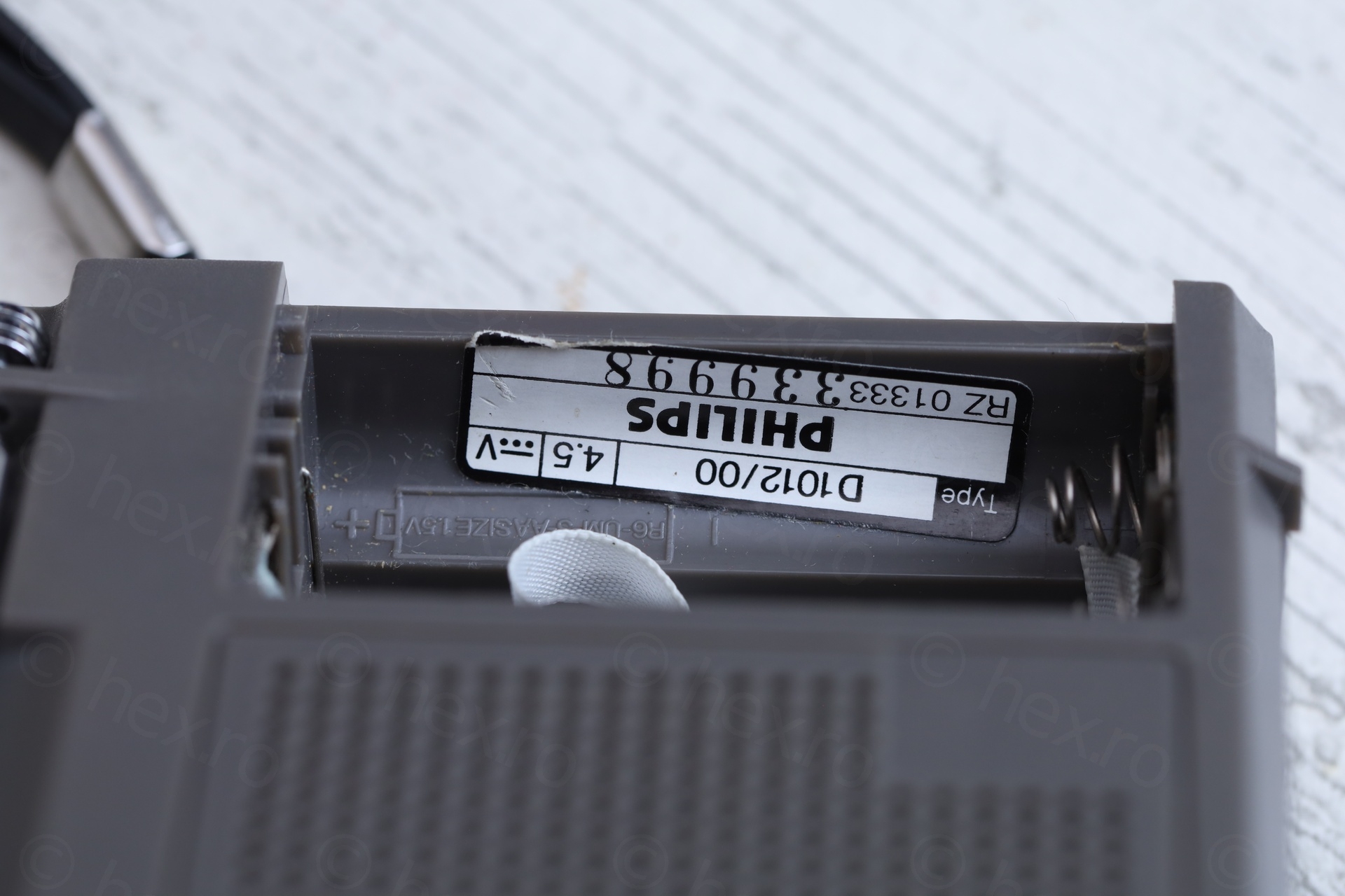
Here’s how the radio looked as bought:

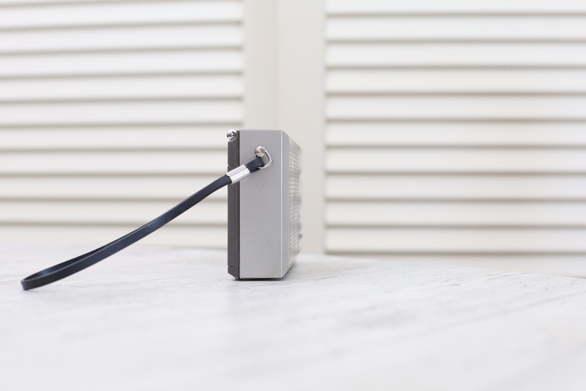

Few things struck me as odd:
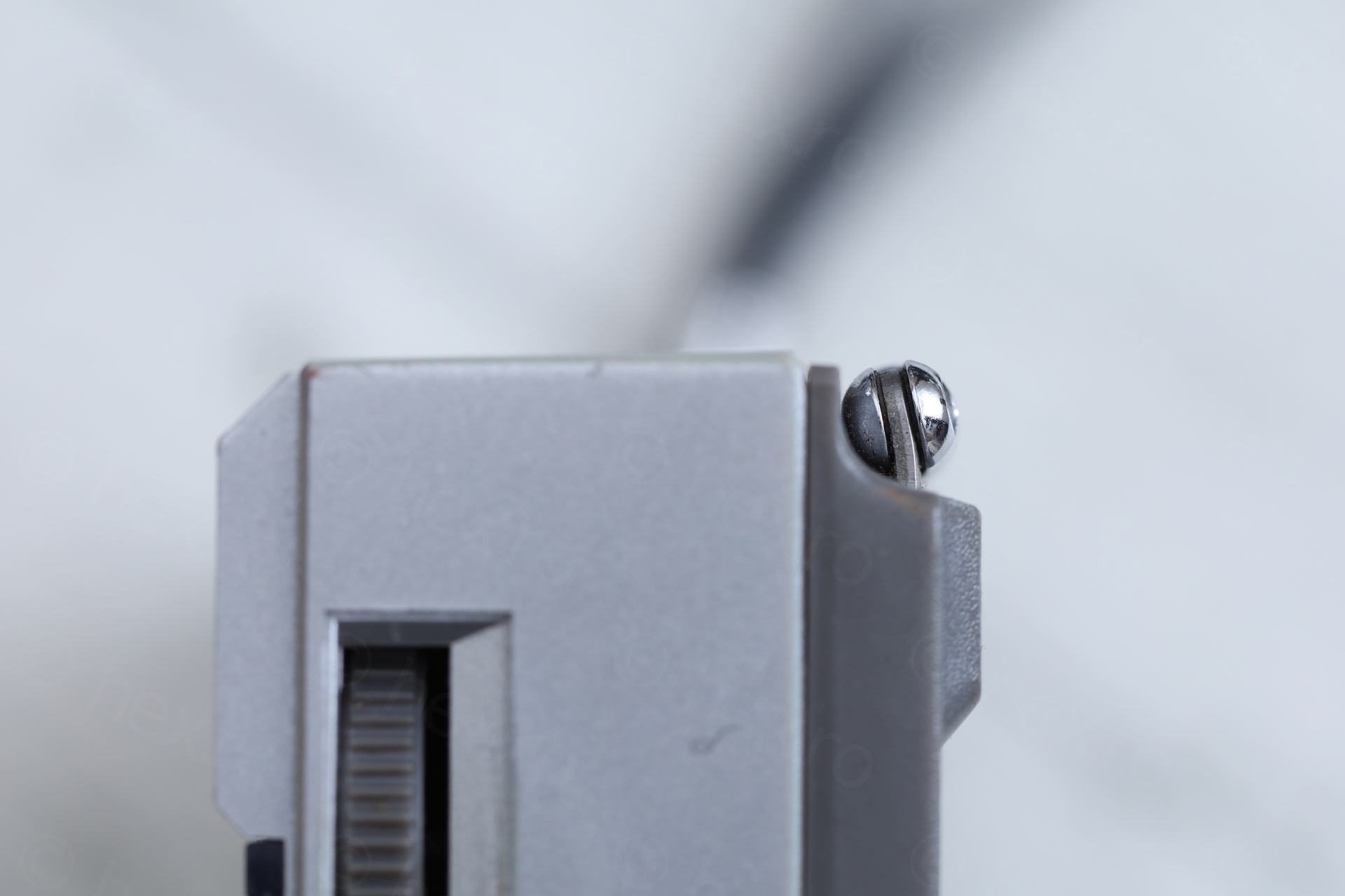
- Tuning knob was rubbing against the plastic case, although its cutout hole had plenty space for it.
- The dial indicator is a diagonal line. At the end of the scale, that line almost pointed vertically.
- The little thumb buttons were too deep inside the body of the radio, I could barely reach them with my fingernail. Especially the On/Off button was hard to reach.
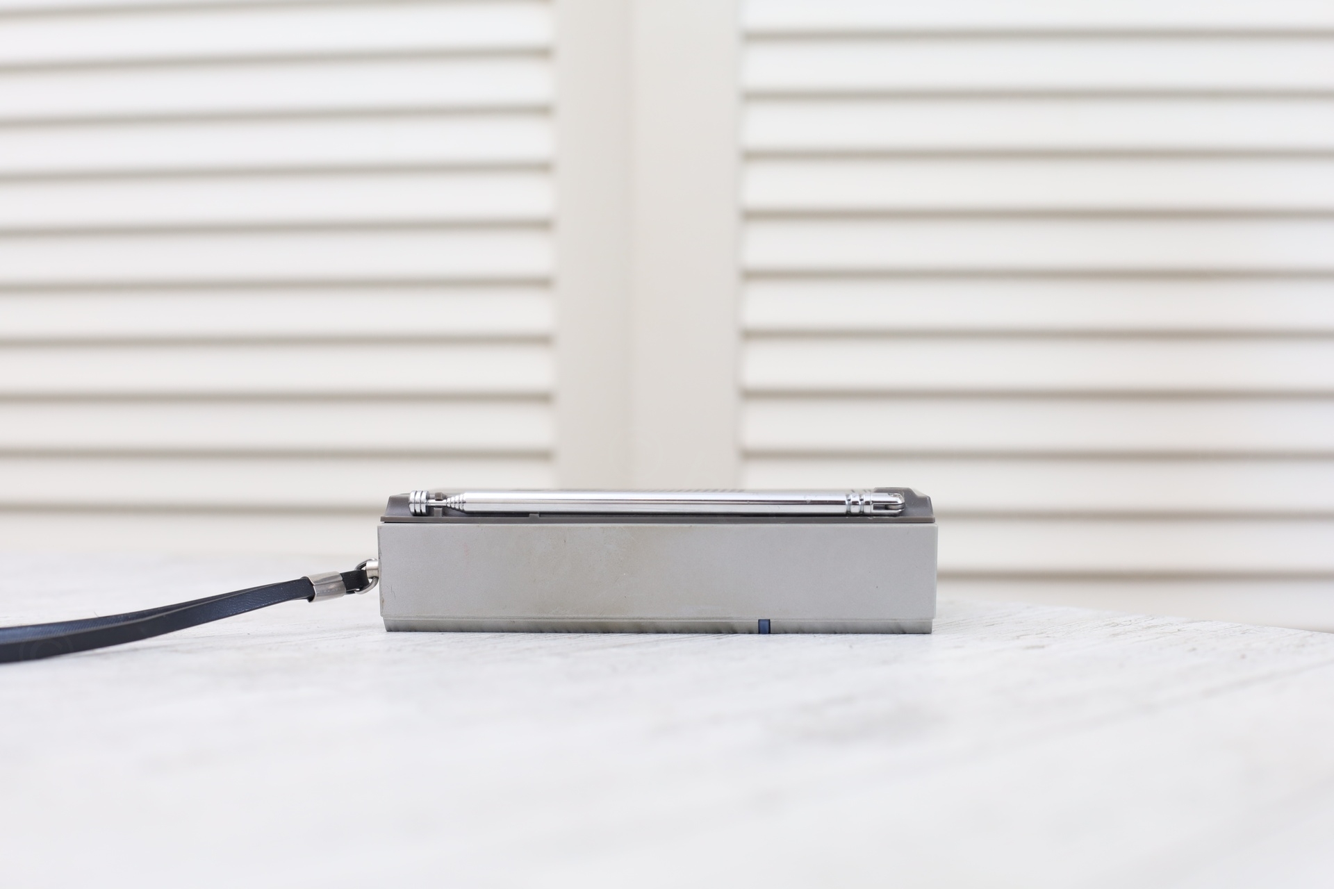
- The antenna mount was tilted towards the radio.
I decided to take it apart, mostly because I could hear something rattling inside.
Problems
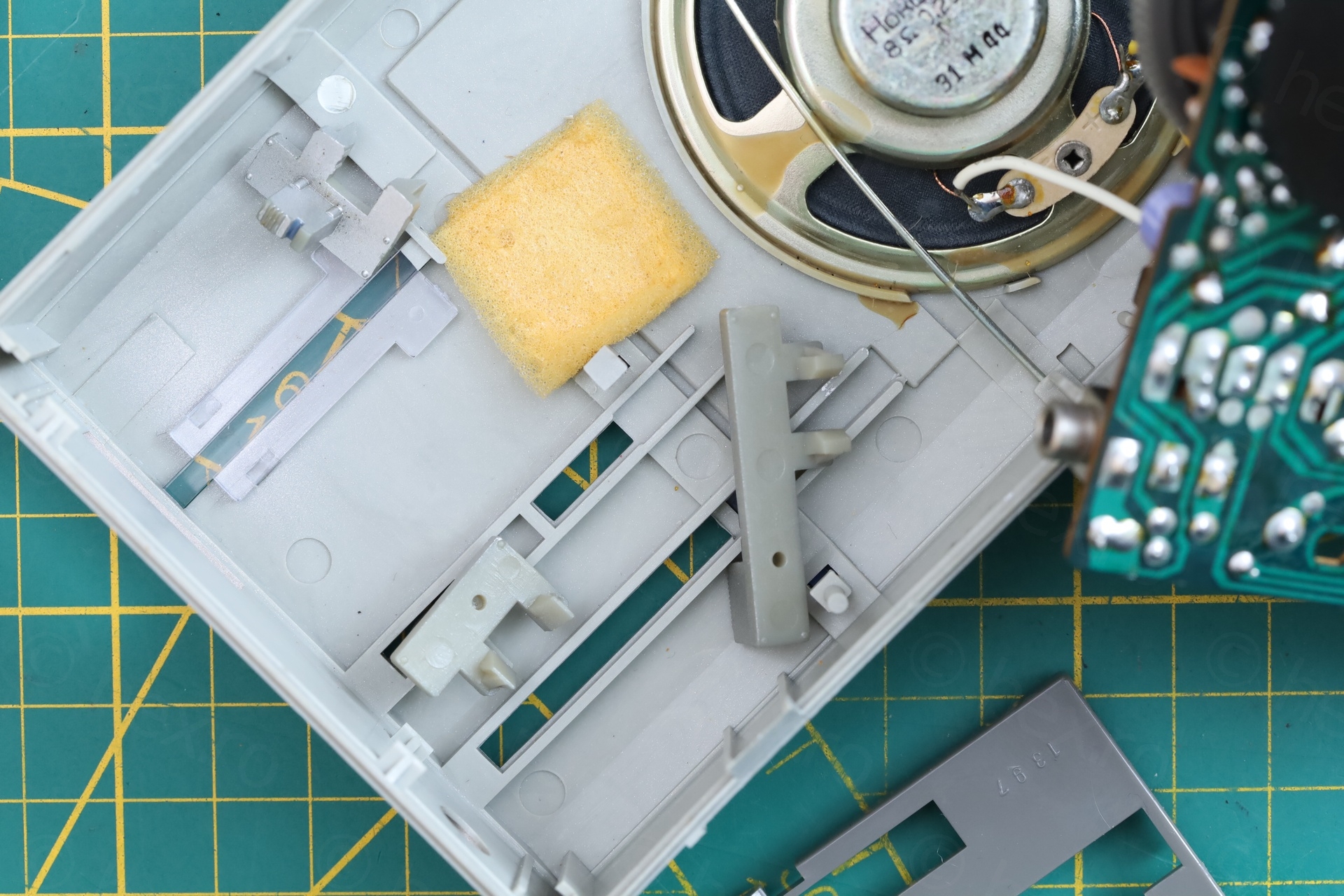
Taking the radio apart, some plastic parts fell off. It seems there is a plastic guard holding the sliding buttons against the front panel. It was loose. I figured the radio fell and got it dislodged – however, there are no signs of damage on the outside of the radio.
Knobs too recessed
The parts that fell:

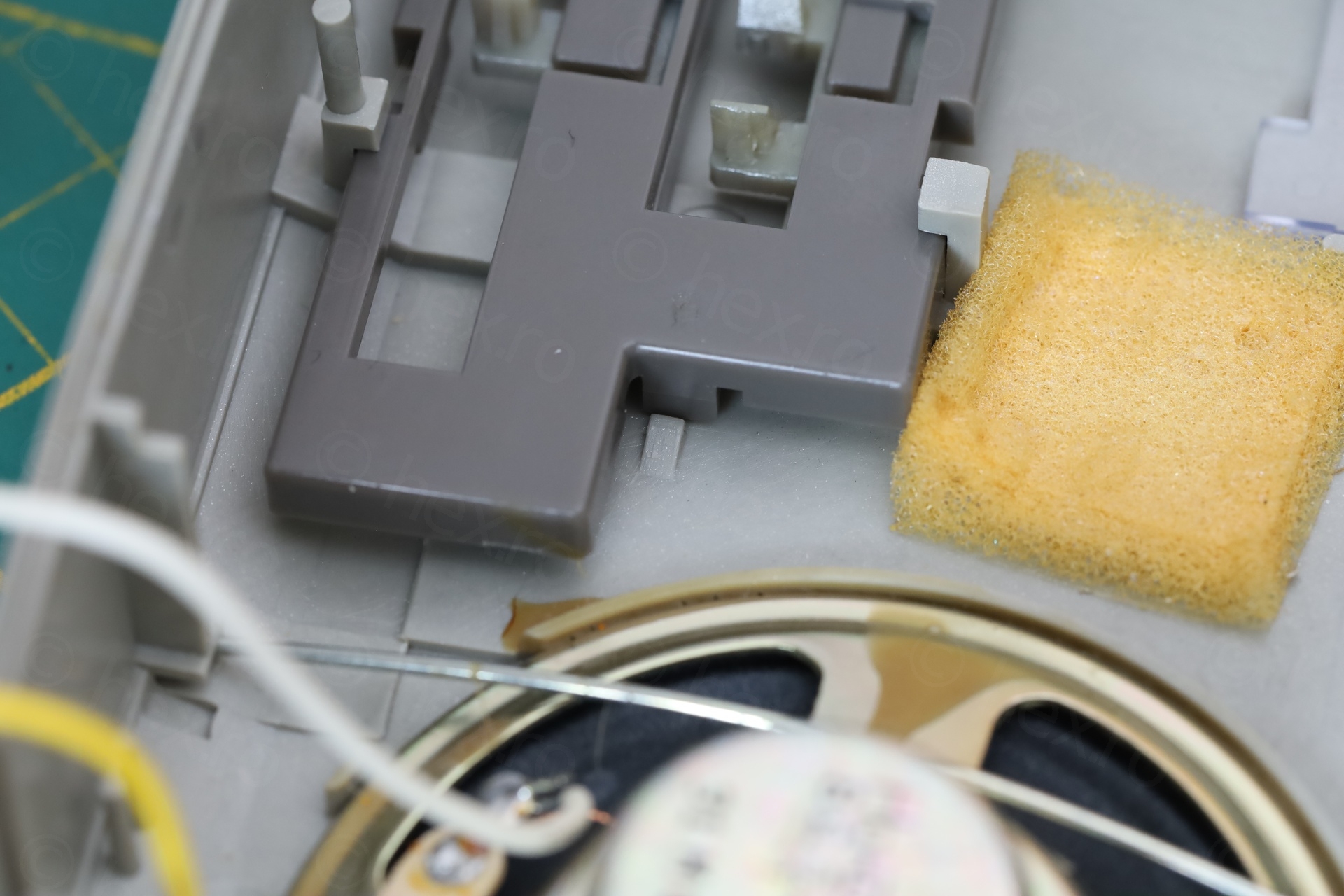
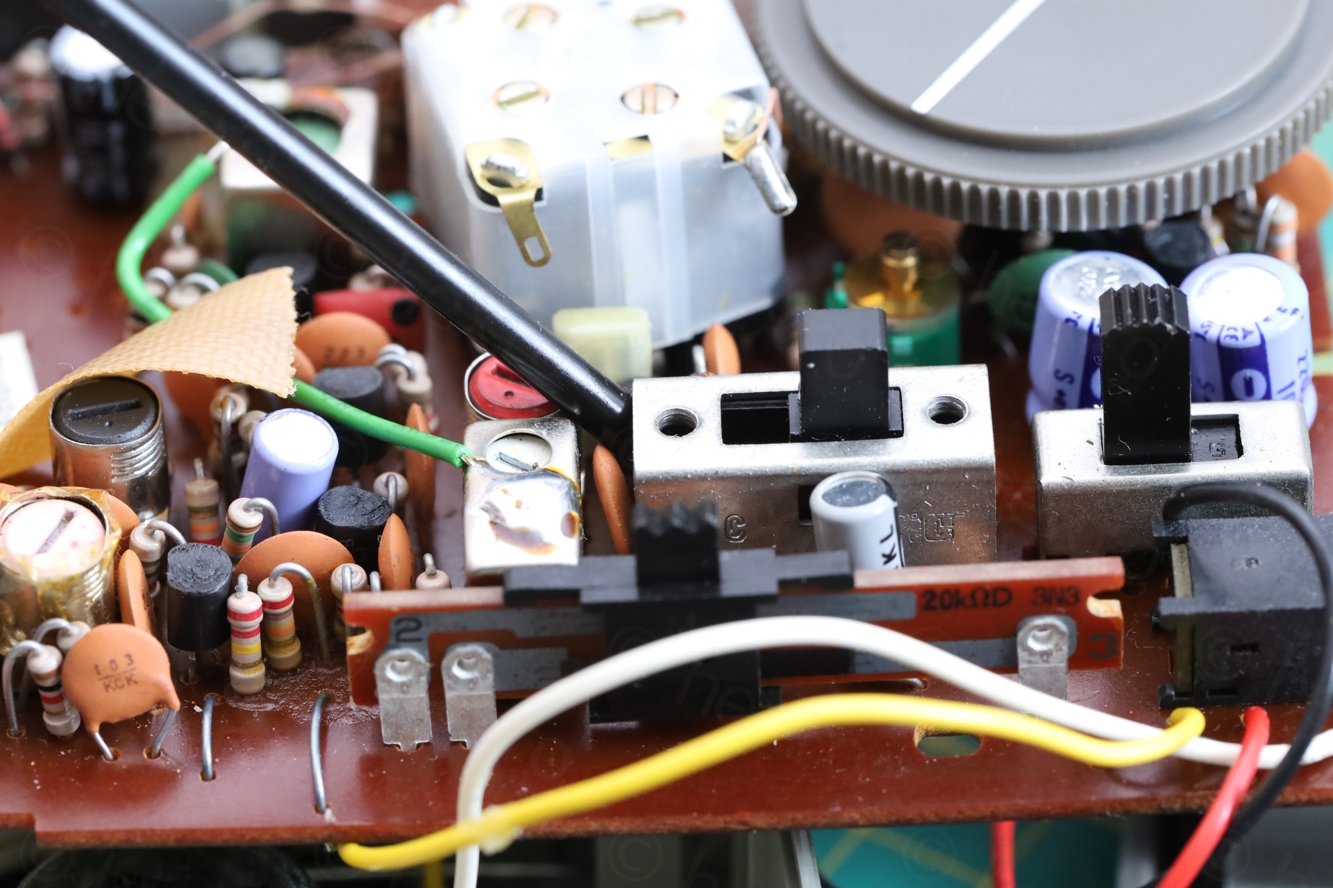
While putting the guard back was easy, the difficult part is to push the circuit board (holding the sliding switch buttons) back onto the knobs – since you have to align the handle of the switches with the corresponding knobs.
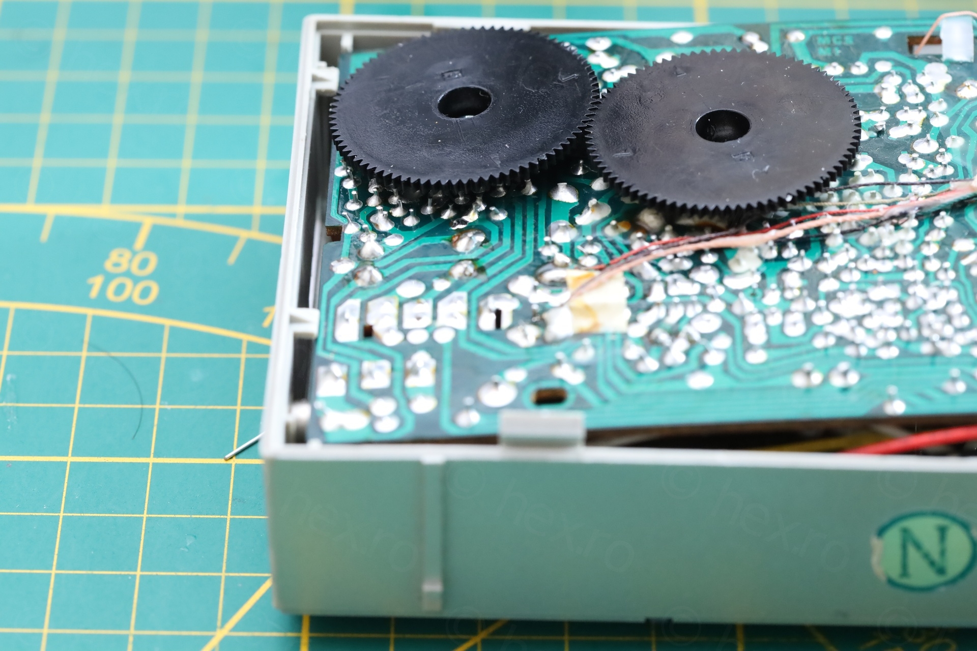
Initially I tried holding the board at a 45 degree angle (to get it to slide under the clips on the left) …
… but the slide button handlers were coming in at a too steep angle to slide into the holes of the knobs.
The easier way was to position it as below and then gently push down on the rod antenna on the right:
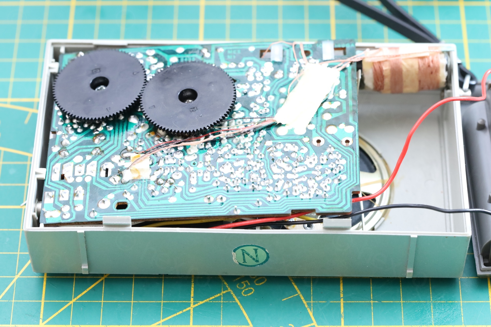
Now the knobs are not “sunk in” anymore – and they can be moved way easier:
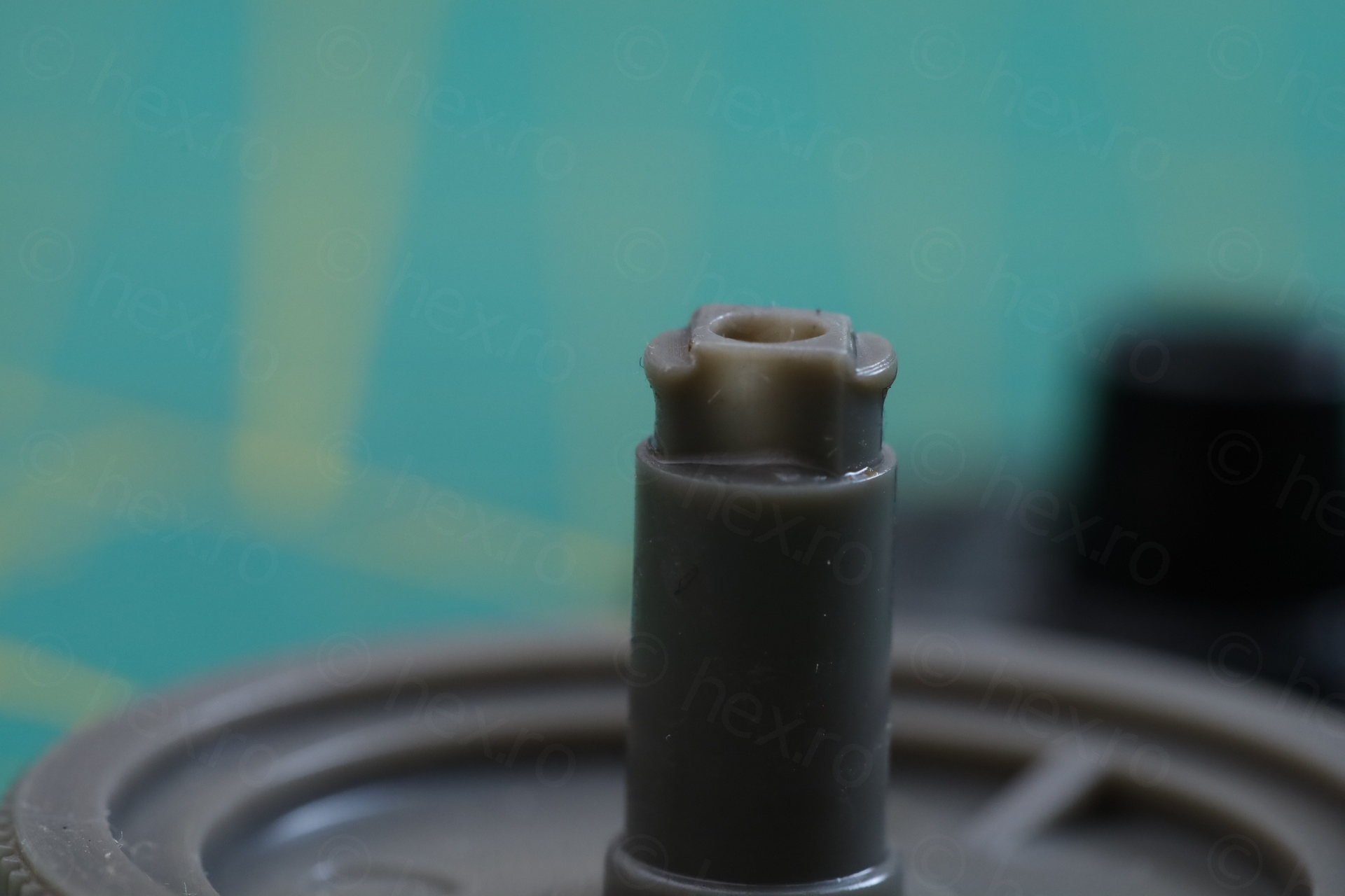
Dial knob shaft
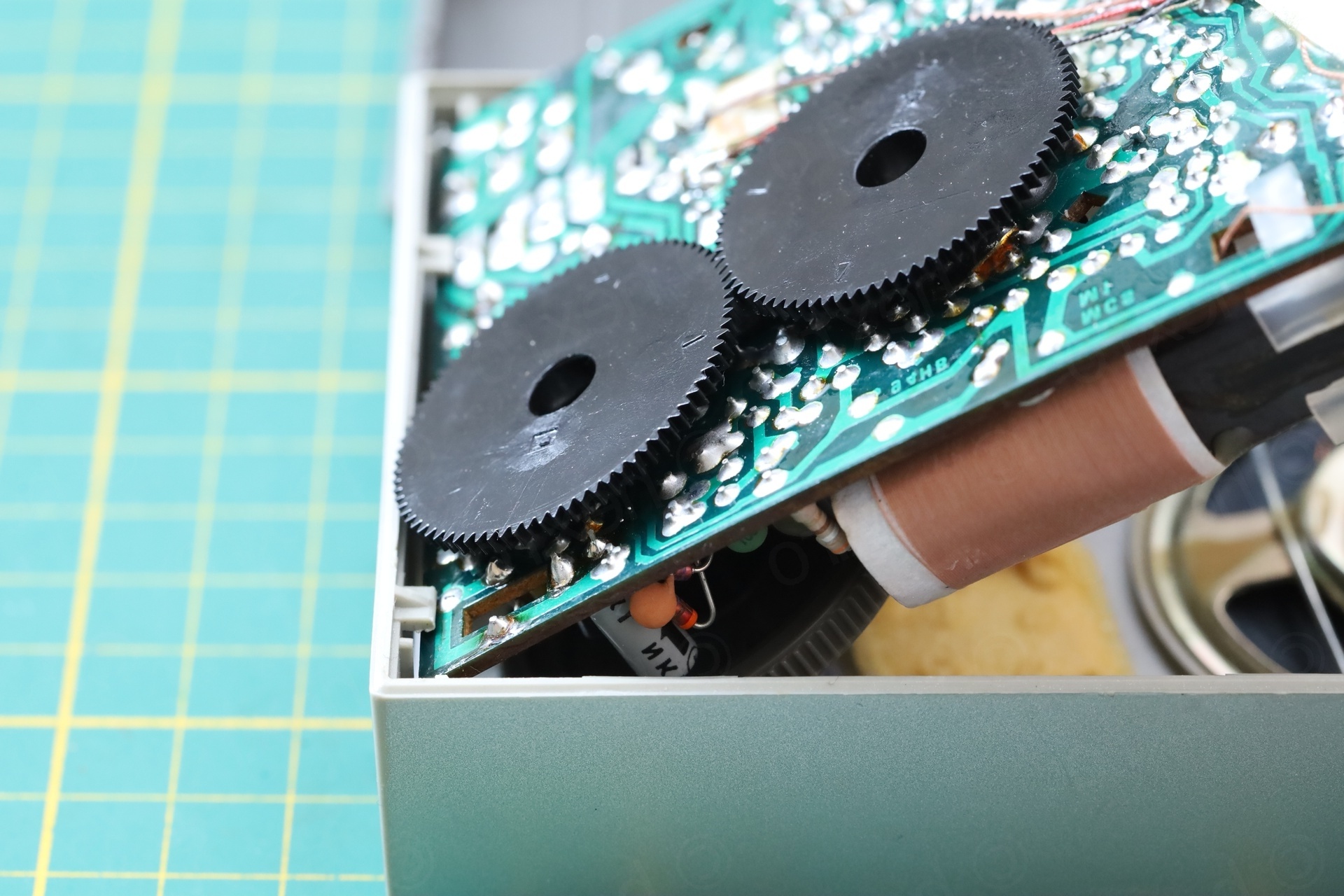
In the photo above, you see also that the dial knob sits properly in its slot, instead of rubbing against the face plate. I had a look at the assembly, while the board was out and it struck me as odd that actually the dial knob could slide through the board, pushing the teethed wheel away:
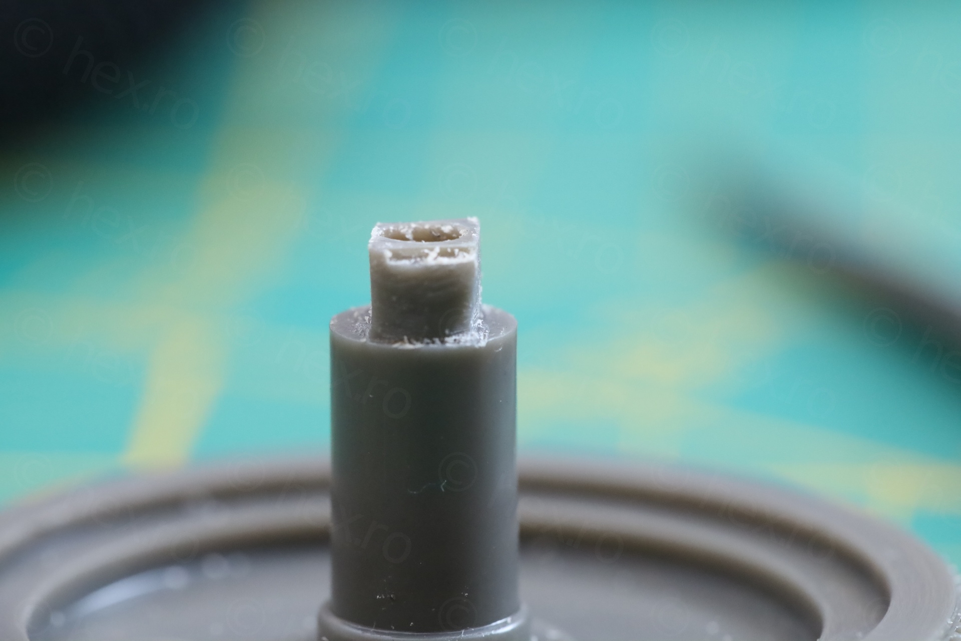
Decided to take the knob apart since I was curious what is going on (first) and to align it properly (so that the dial indicator line sits horizontally at the end of the travel). Surprisingly, I found the plastic shaft was deformed and the two would not mesh in fully ??
I started to think that this may have been a factory default – I mean, you would probably need to push really strong to deform it like this, no person would do this ?
Anyway, a bit of filing later, and everything is good as new:
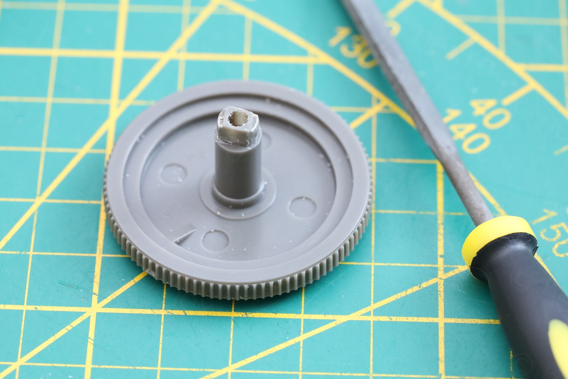
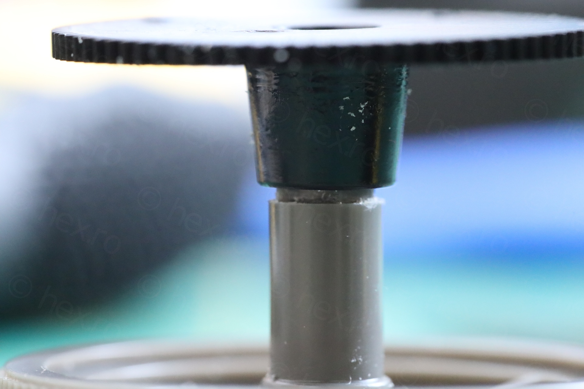
There is no more play now and the knob stays in the right position, without rubbing on the face plate.
While arranging the knob back, I noticed that the knob turns very closely to a Litz wire coming off the tuning capacitor. I fixed this with a little wax, thus clamping the wire to the capacitor, away from the knob. It is not permanent, I did not damage anything, but at least it is better protected:
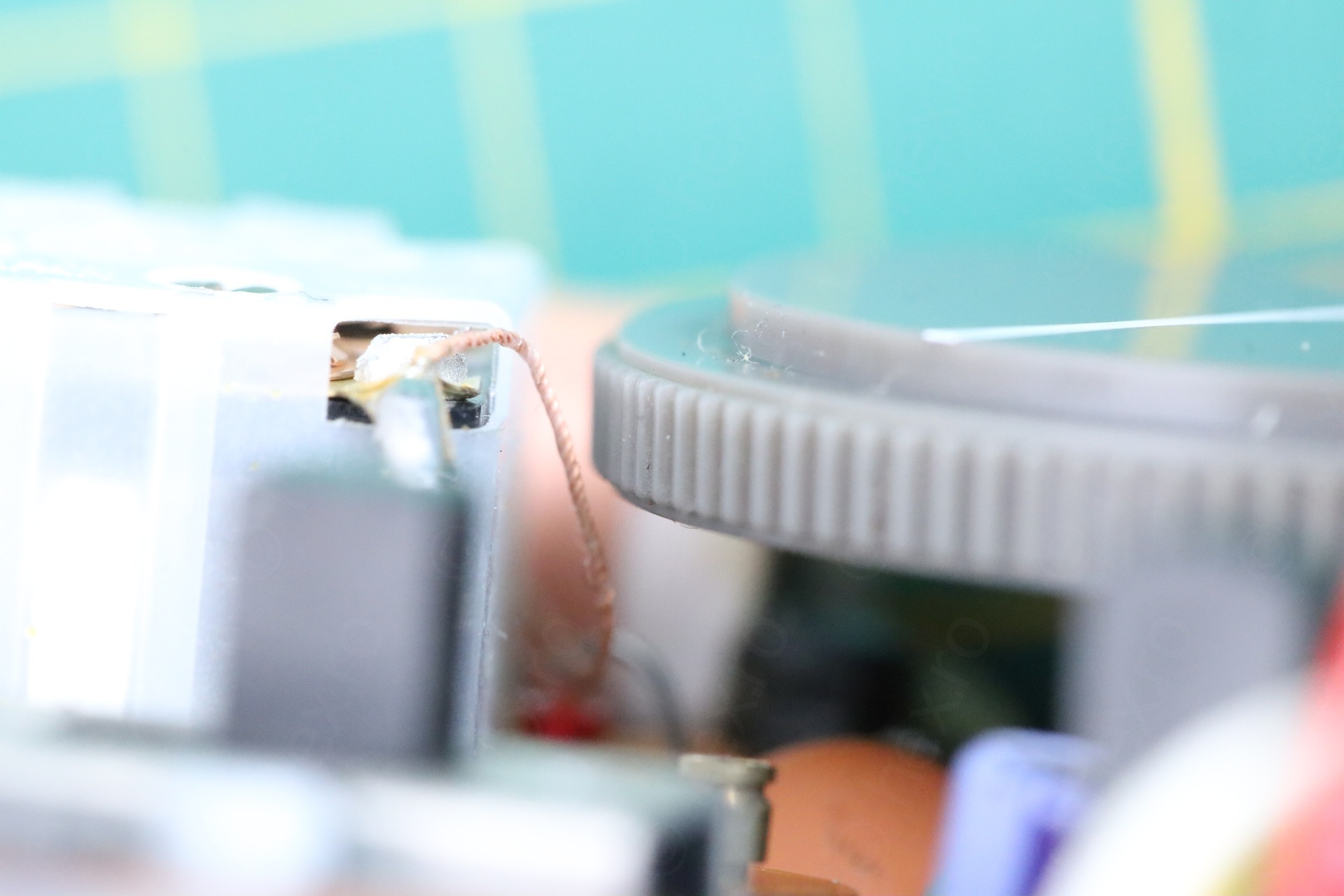
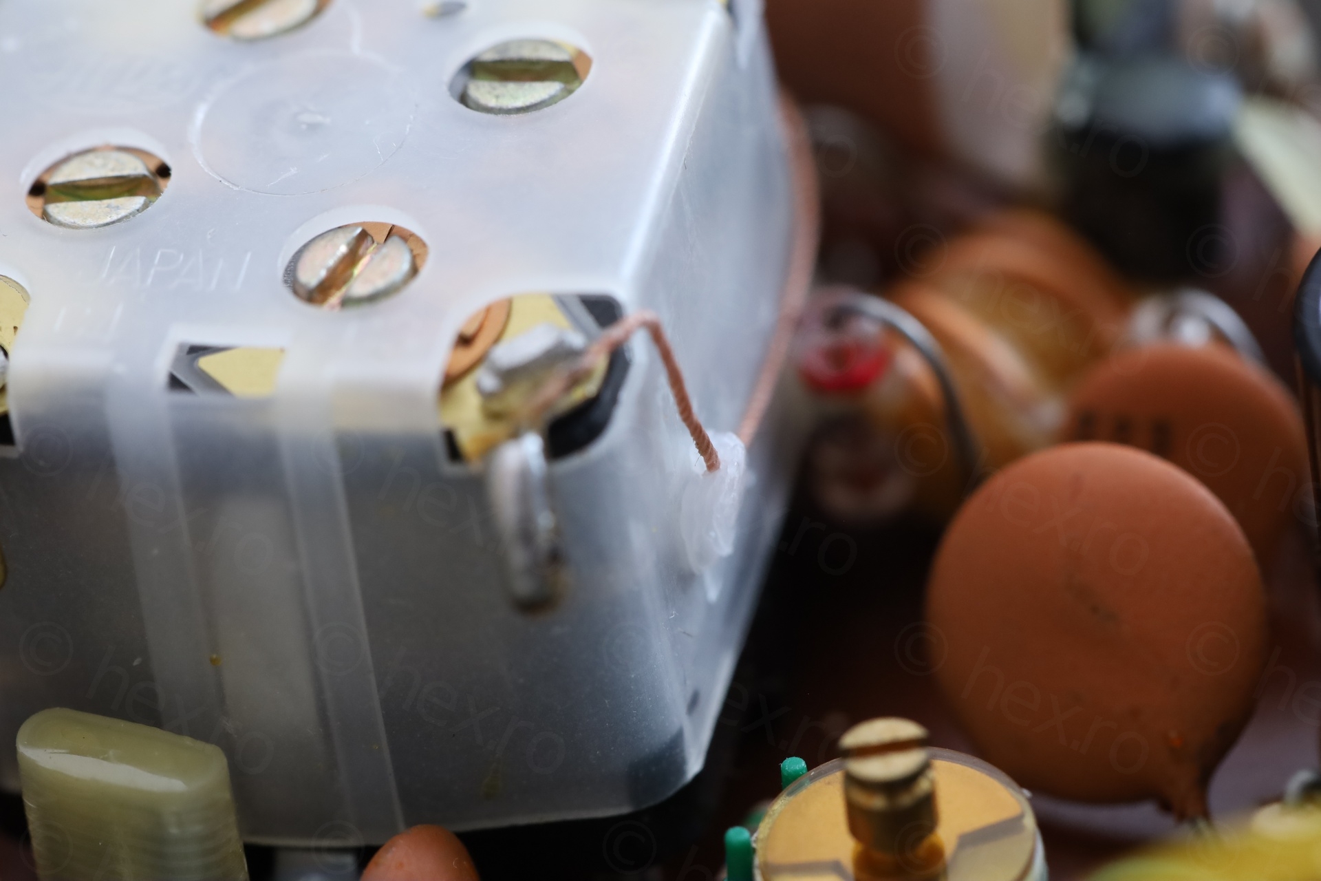
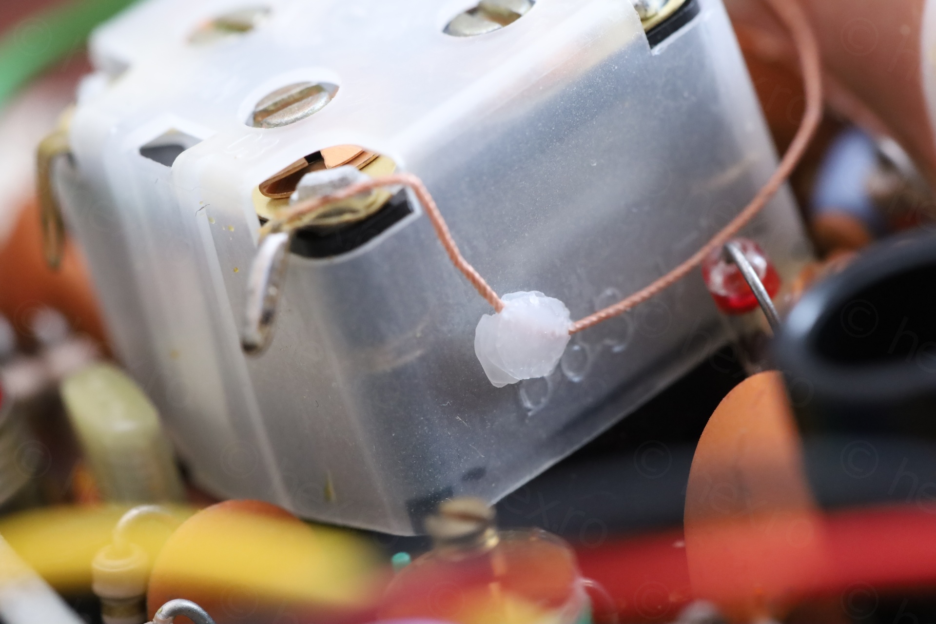
To apply the was was a little tedious: got a tealight candle hot enough and then, with a warm screwdriver, trying to scoop melted wax and applying it. It worked fine.
Corroded capacitor
By now, I had already tested the radio and everything was fine. I was not in the mood to re-cap it since there were plenty loud AM stations during the night.
I don’t really listen to FM (nor DAB). What speaks Radio to me is AM and catching far away stations (I guess nostalgia ?). I would like AM to be back, but I do understand its shortcomings for most people. And that it is costly to emit.
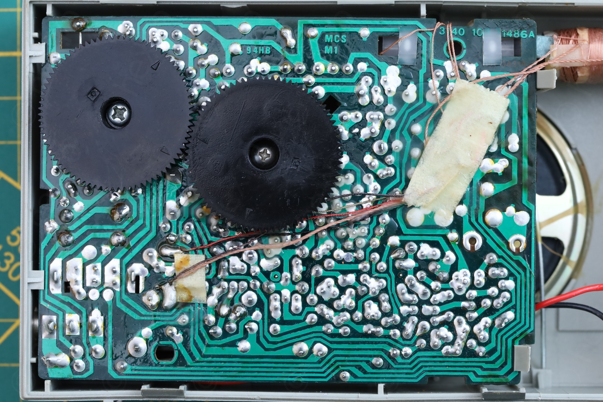
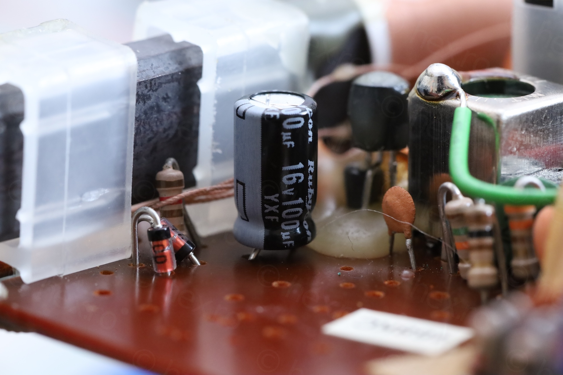
Looking at the board, I spotted something weird though, a single capacitor with blue legs. Not only it was corroded, it was also measuring Leaky on the tester:
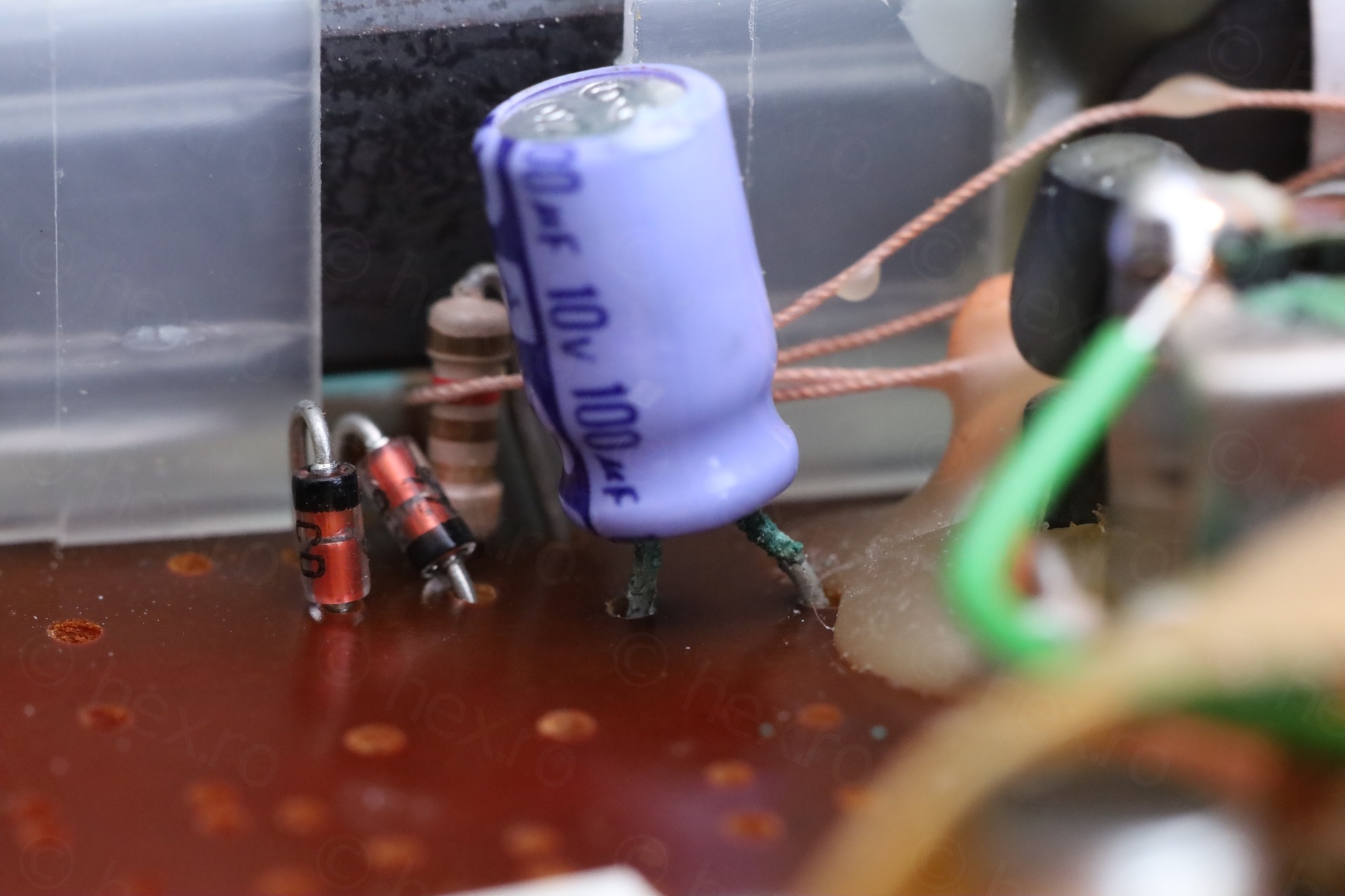
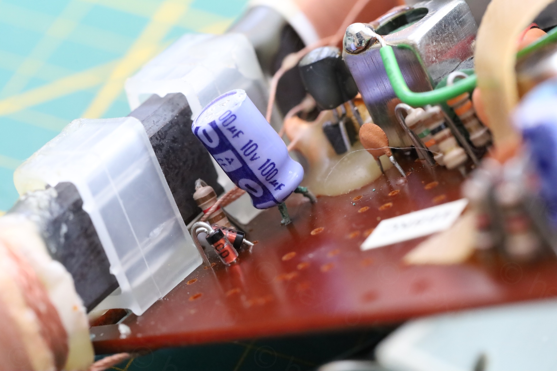
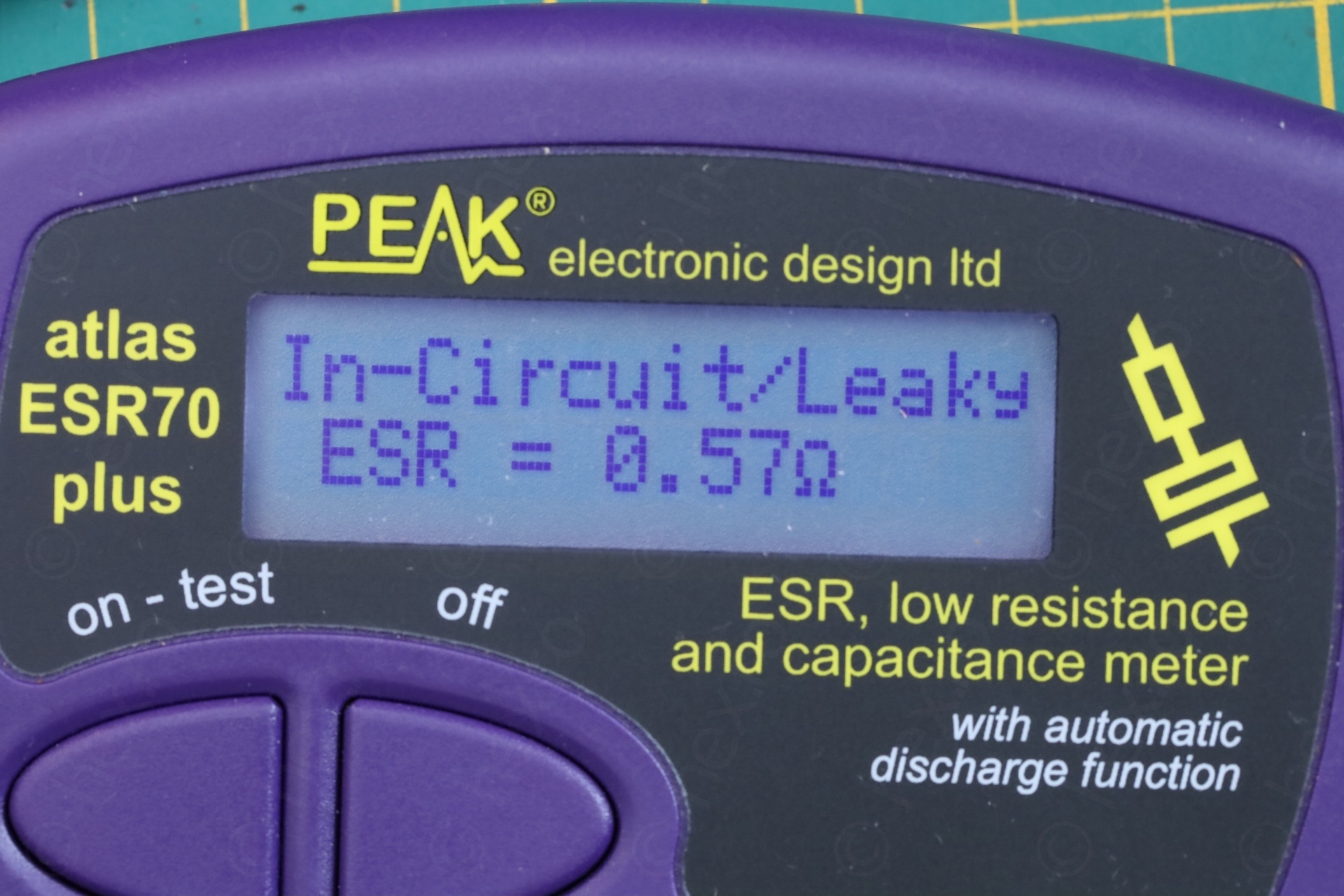
But radio worked perfectly with it. So what’s the deal ? I took it out mostly out of principle, as in, corrosion should not be left in. But, once out, the capacitor was actually measuring perfect:
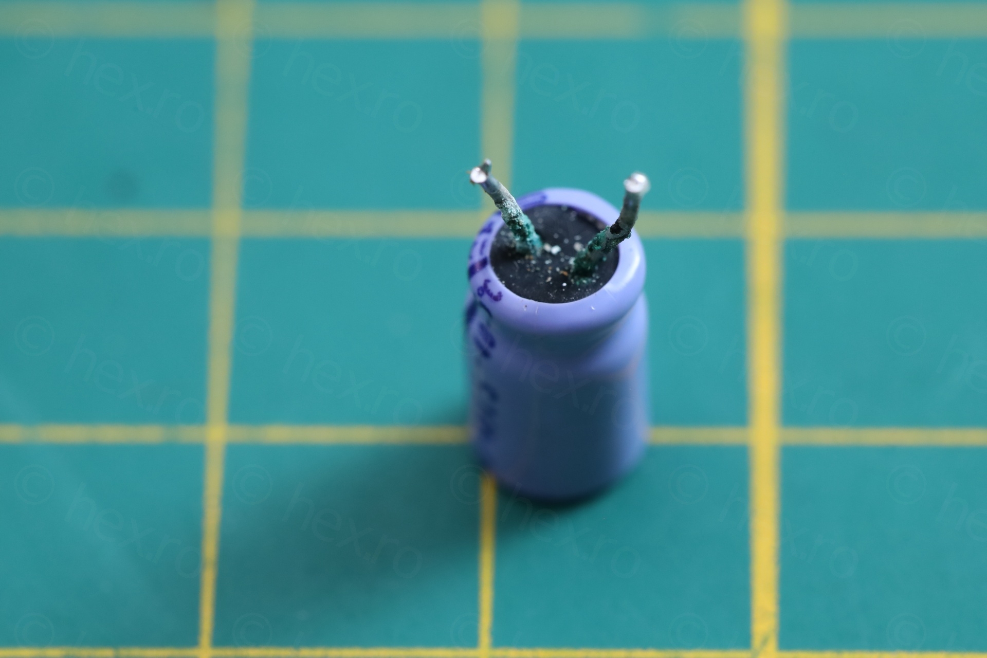
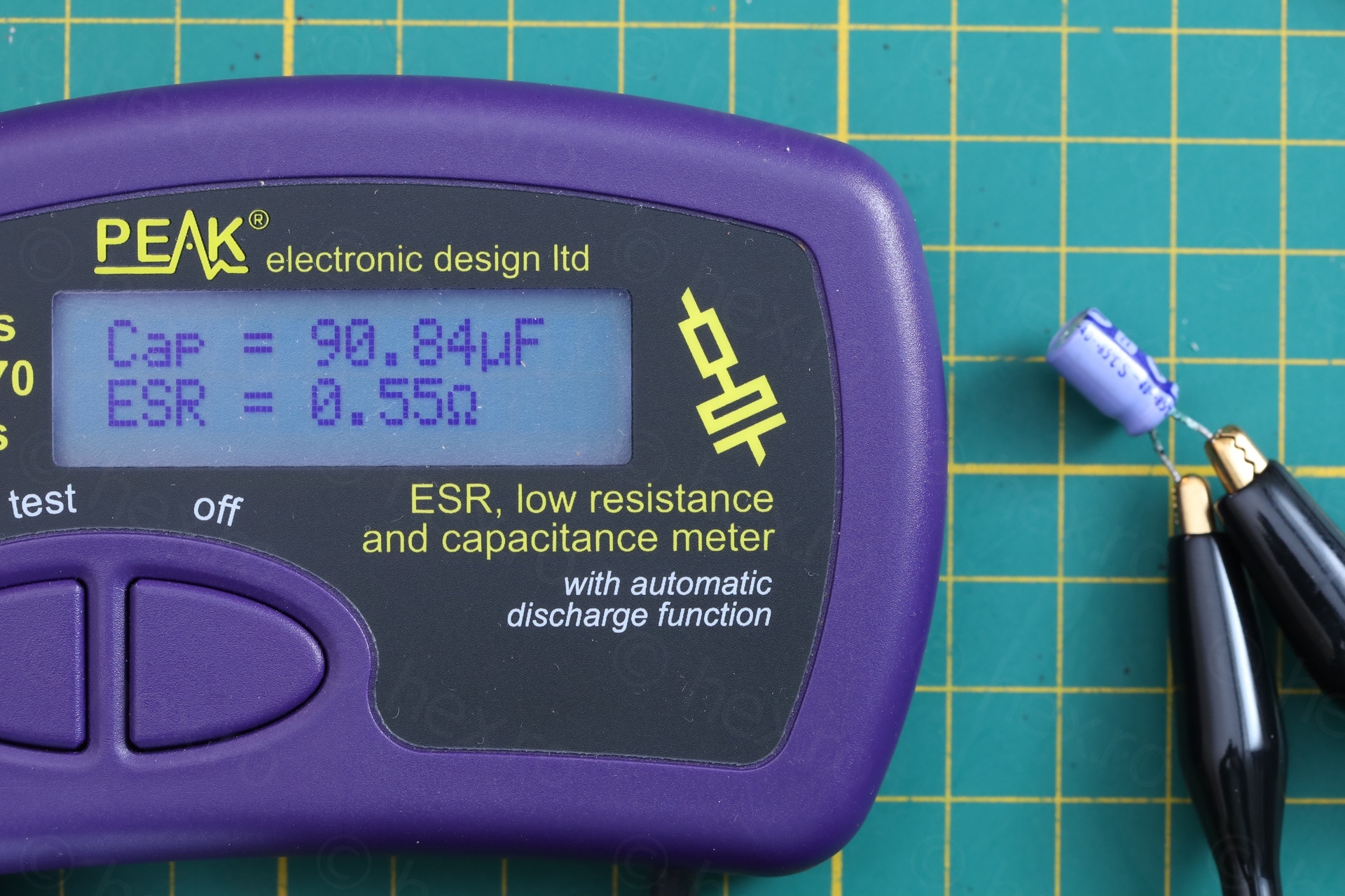
Puzzled, I decided to proceed to an autopsy and see how far the corrosion got inside. I was surprised to find out that it did not. The metallic pins are stuck in a corresponding sockets inside the capacitor body. Corrosion did not pass those sockets, it reached them but it did not pass:
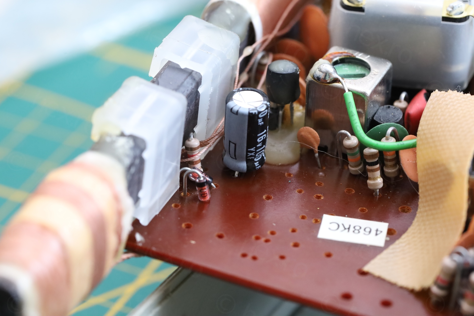
This explains why radio was fine with it. Replaced the cap with a Rubycon of 100µF @ 16V (vs. the original, a 100µF @ 10V):
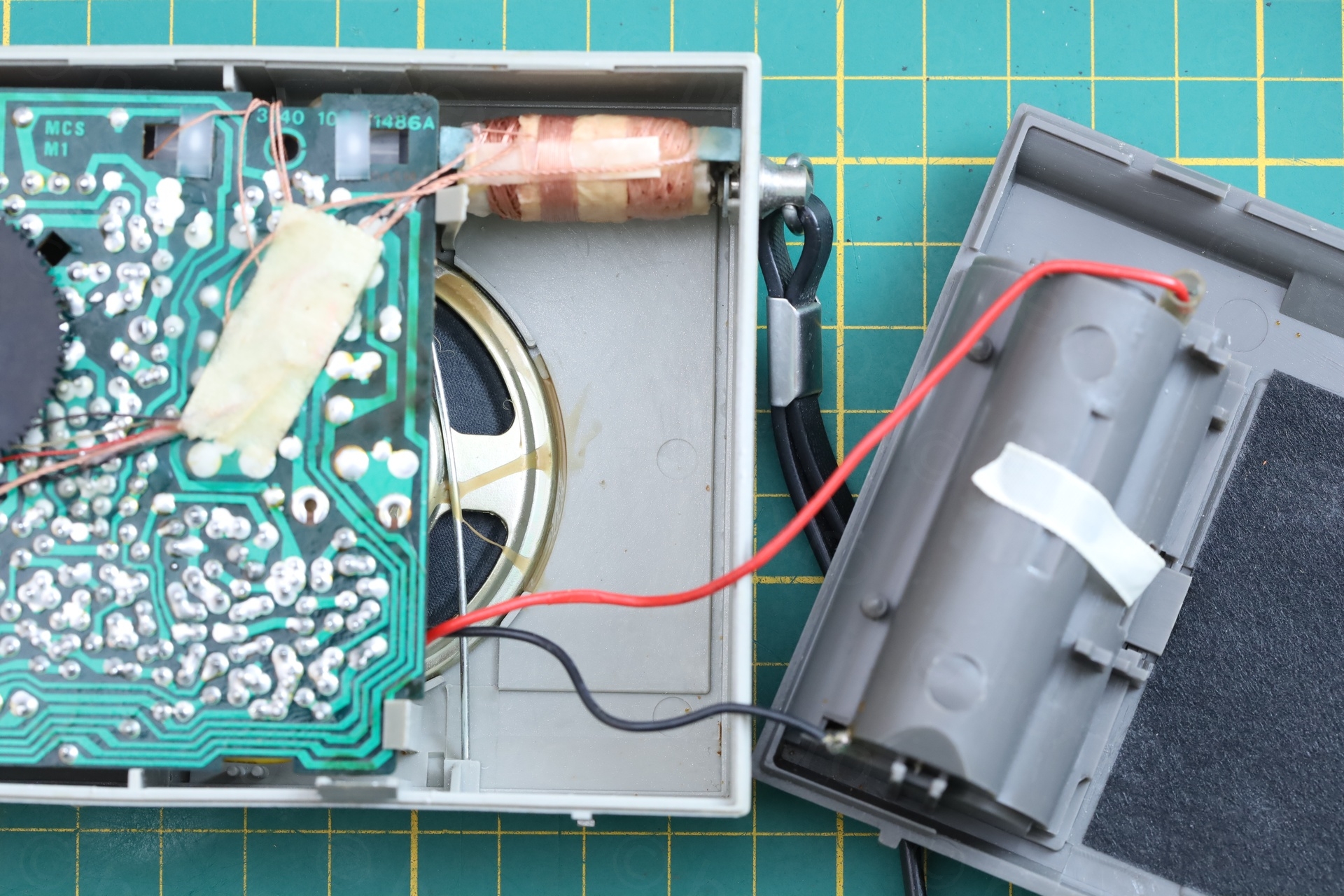
Battery Negative wire
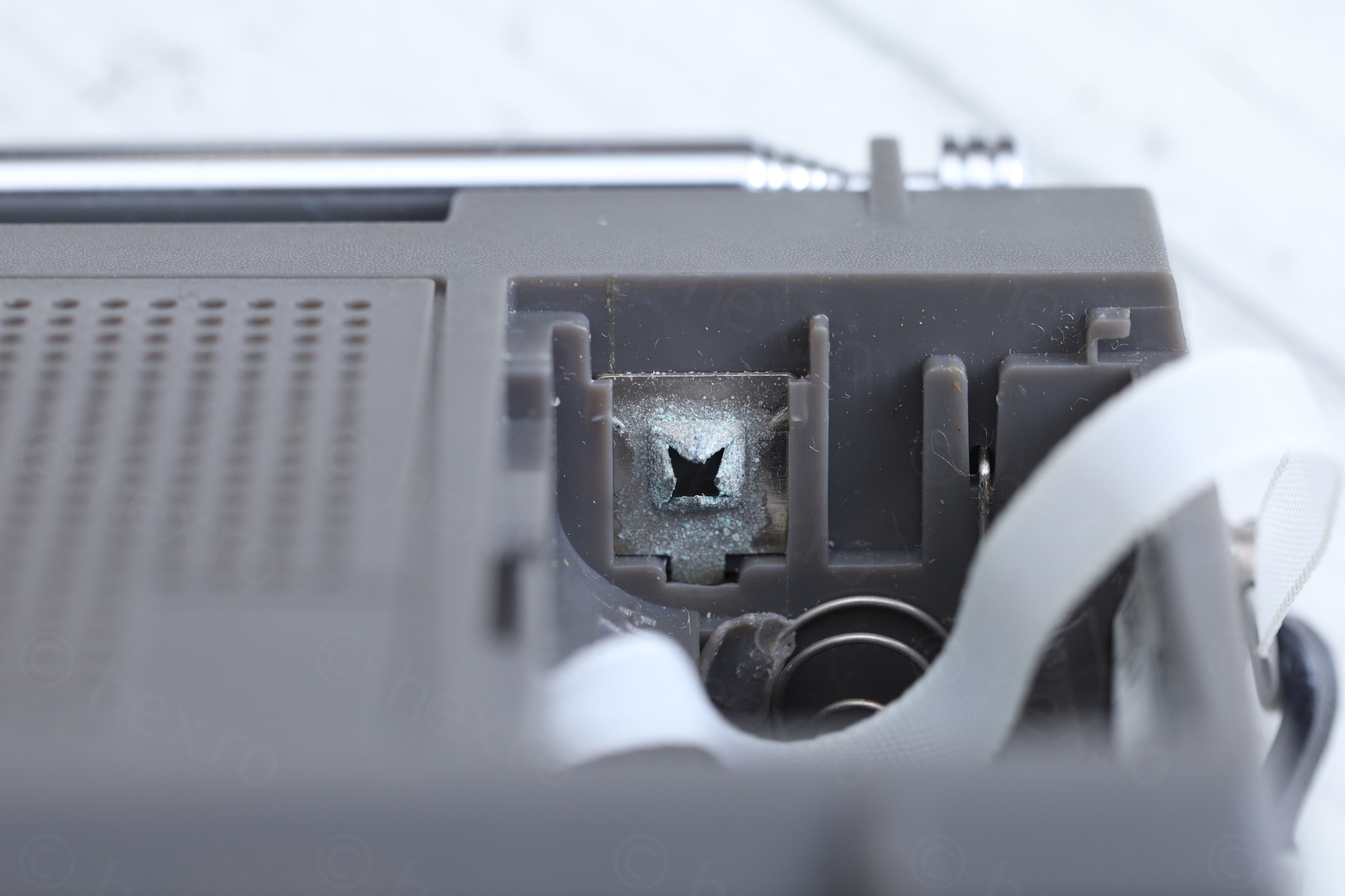
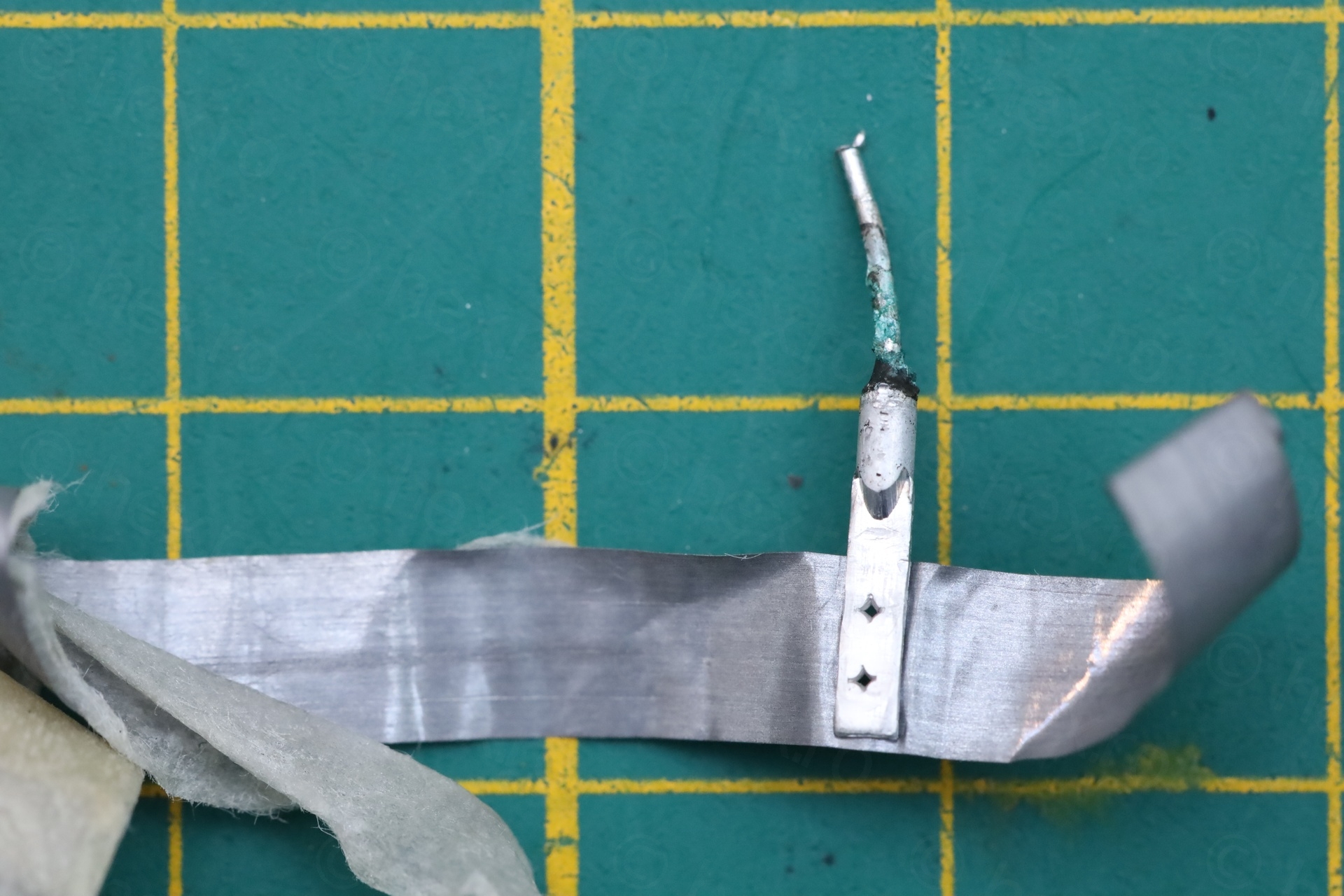
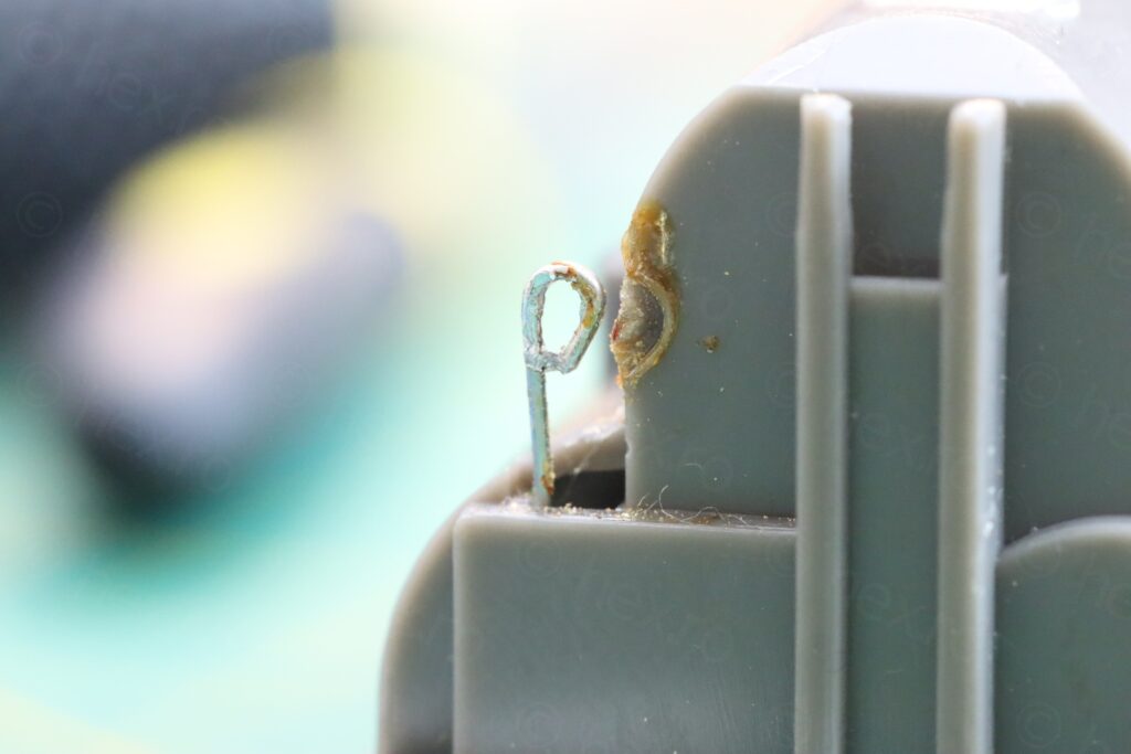
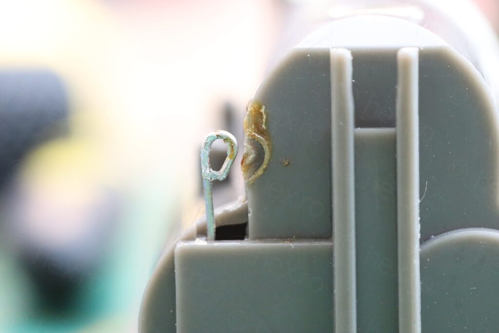
Very early on I spotted that the black wire was not well connected to the battery holder. I wanted to re-solder it, but only then I noticed something interesting. There was no insulator (as it was on the red wire) and remains of the old wire were still there. Not only that, but the battery holder wire was melted onto the plastic, as if somebody pushed against it:
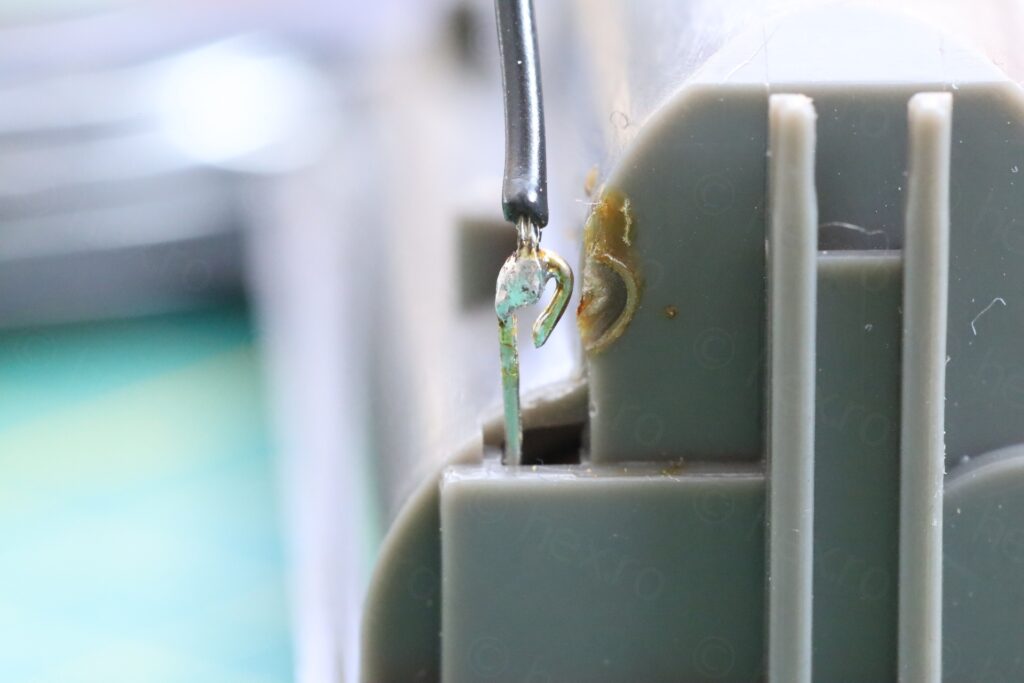
I decided to clean up: sucked the excess solder with a vacuum solder sucker, to avoid putting more pressure against the battery terminal and melting more plastic. The fastest, smallest pressure is with an electrical vacuum solder sucker. Afterwards, I moved the battery holder pin away from the case and soldered the wire back, while adding a piece of insulator:

This radio is a mystery. It looks like somebody was inside and that person failed to reassemble it the right way. Thankfully the damage was minor and I was able to remedy the problems.
Final touches
These were to apply some contact cleaner on the switches…
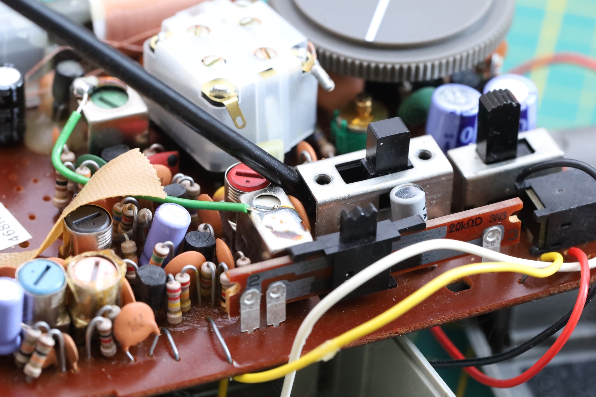
… and cleaning the corrosion on the battery terminals. Also, made the antenna sit a little more vertical.
Dial indicator is now horizontal at the end of travel:

In conclusion
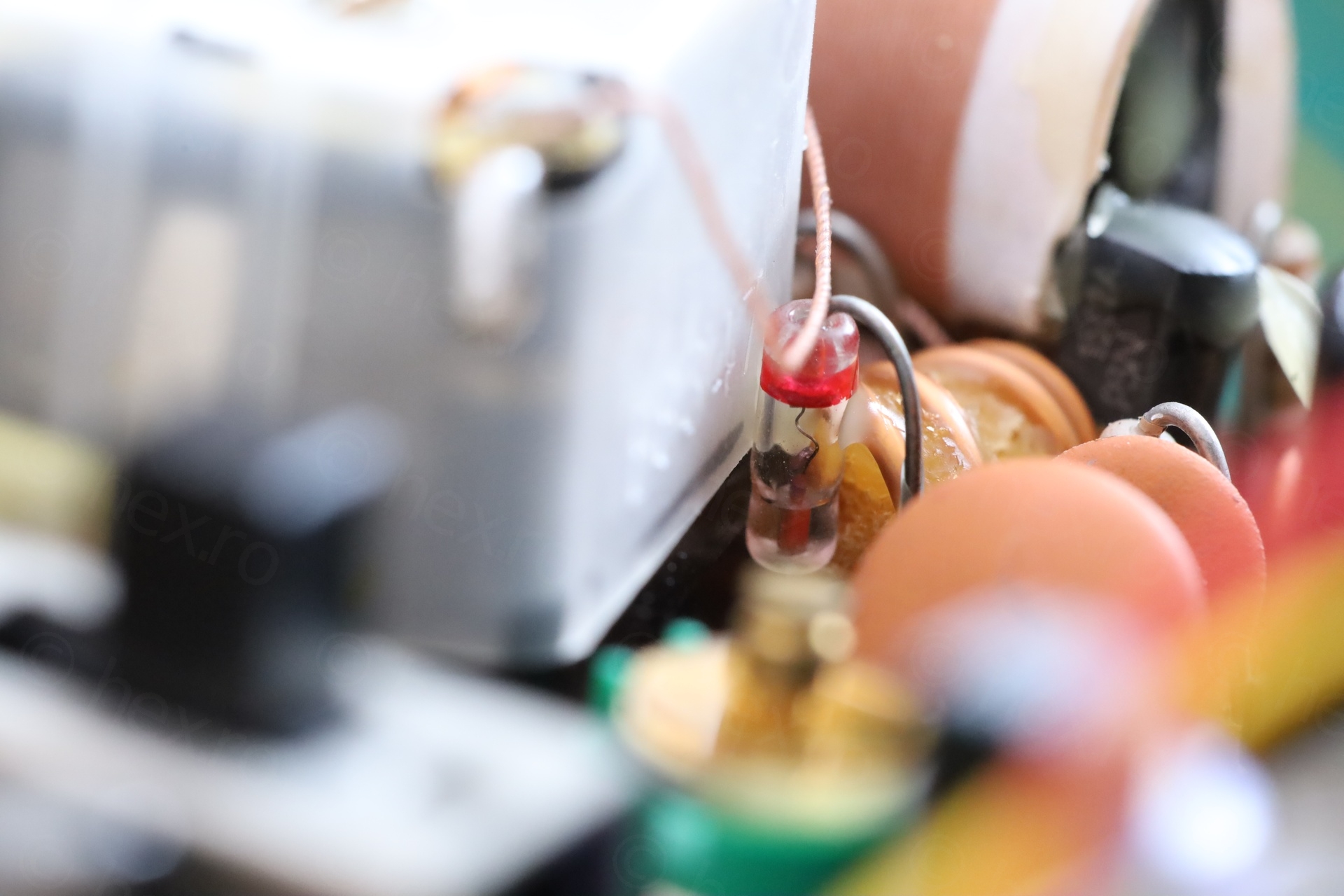
Not only that the radio is analog – it also has a proper Germanium detector diode 🙂
A hot radio, small, rescued from the dump which required small repairs and future proofing.
Leave a Reply