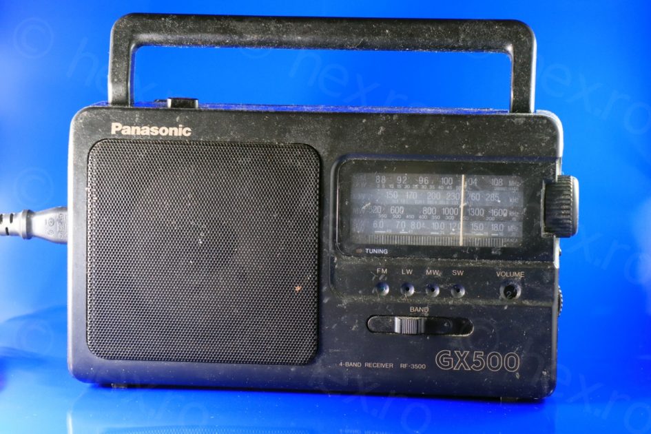
A friend asked if I could have a look at his Panasonic RF-3500 radio, which, he explained, exhibited very low output volume. I agreed, both curious and reluctant, as I have never attempted to fix a radio before.
Initial checks
The radio exhibited very low audio output. It seemed to tune properly (at least on FM): with volume to the maximum, you had to hold the ear close to the speaker, but you could hear clearly the stations, except, the audio level was very very weak.
There were no stations on the AM bands, except, the hiss was a little stronger than FM. Belgium has stopped AM transmissions so I was not expecting any station. However, what was weird, was that the tuning light was always ON no matter if the radio was tuned to a station or not.
The history of the radio was that it was working properly for some years (used in the kitchen) but then it was put to storage for some more years. Upon trying to reuse it, it exhibited the issues above.
Opening it up
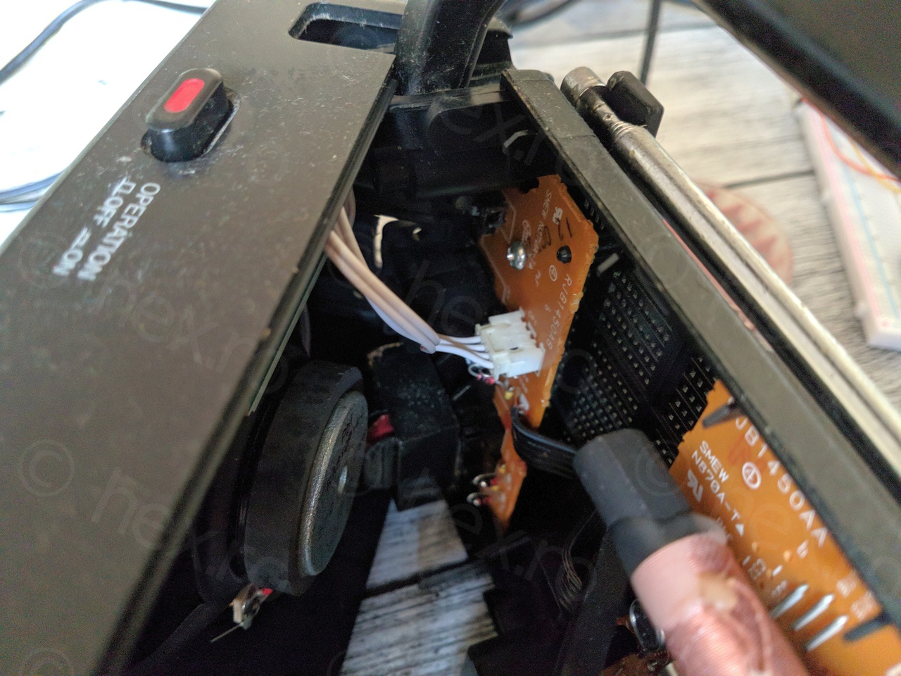
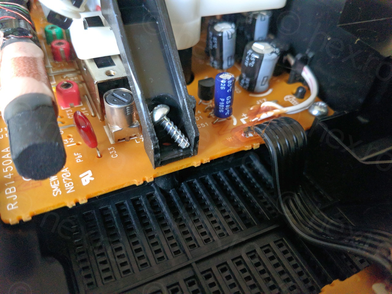
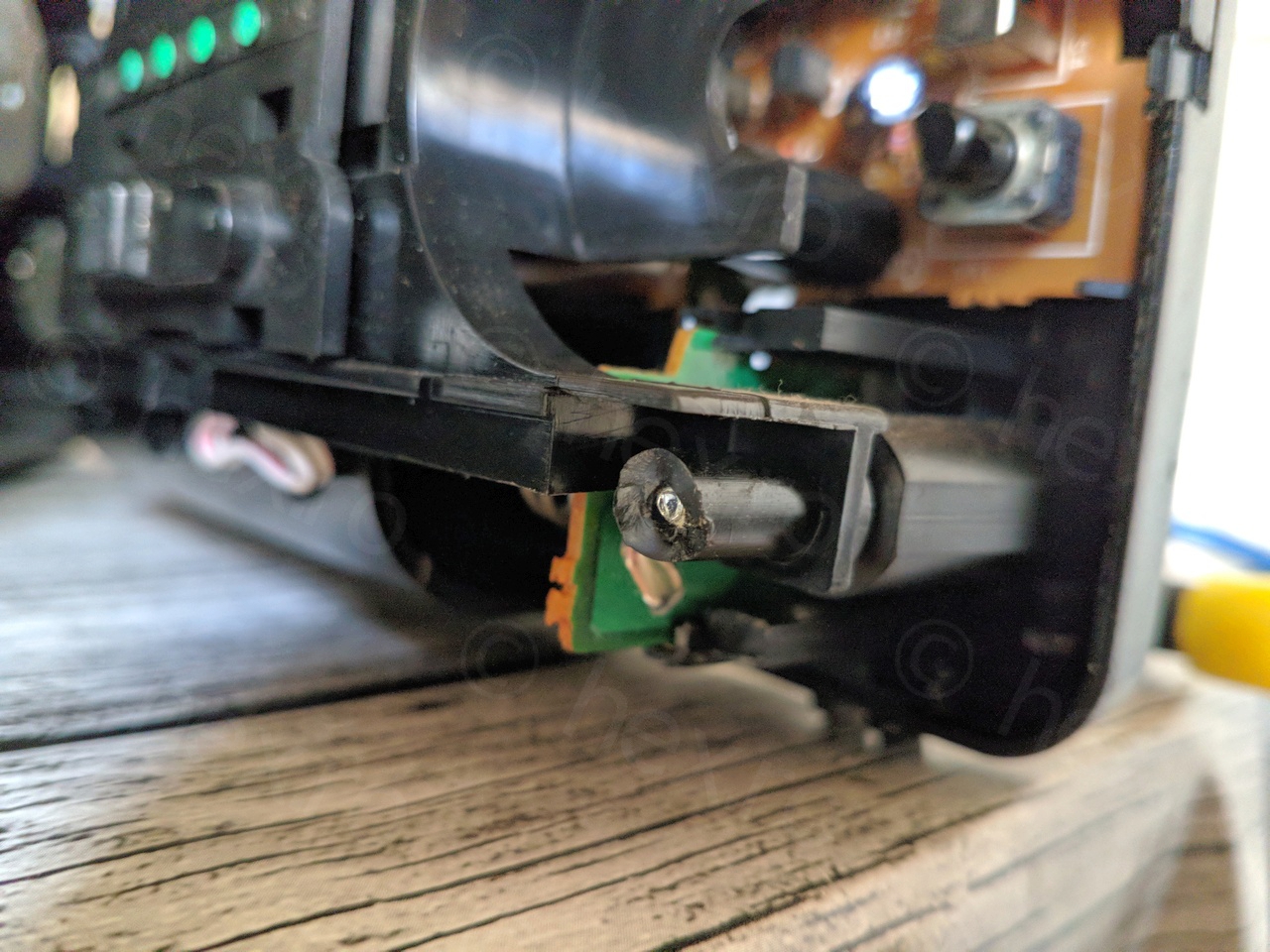
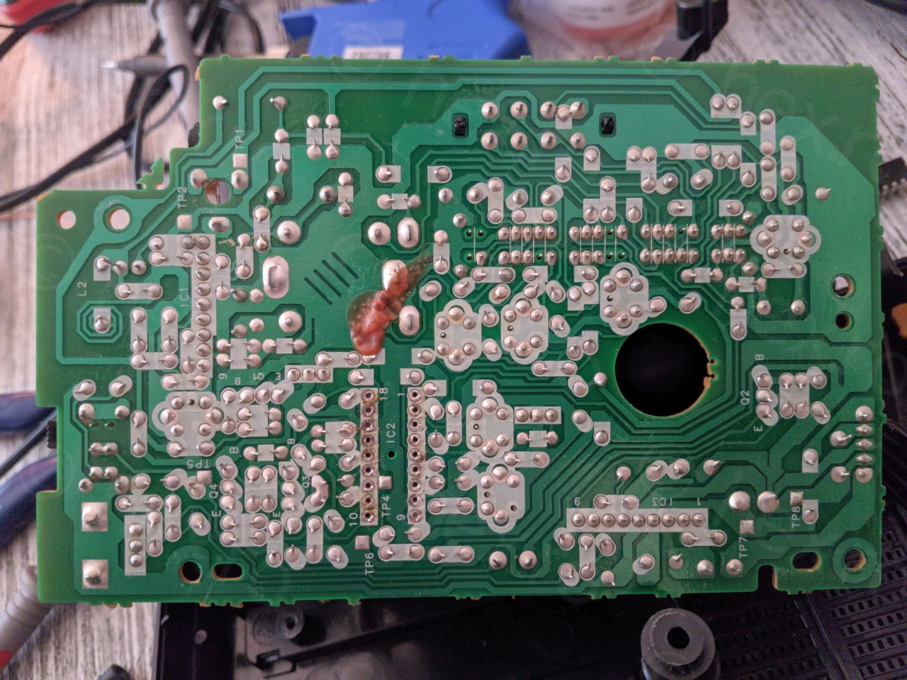
Opening the Panasonic RF-3500 is straightforward – just take out some screws. The trouble is that the screws almost got welded to the threaded plastic poles, and one pole gave up in the process. Please check photos below.
Diagnostic
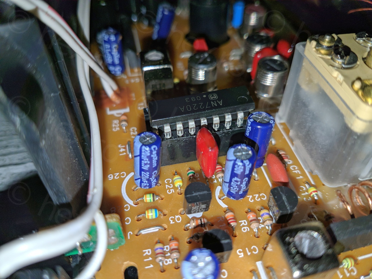
The audio output stage (IC3 / RVIBA557) was suspect, but there were some loud pops when switching bands. I injected an audio signal onto PIN 10 of IC2 / AN7220A chip, and the sound was clear and powerful. The problem was not the audio out circuitry.
I suspected also the capacitors (CapXon brand) which have a bad reputation online (here, here, etc..) but since there were many of them surrounding the audio output IC3 which was working fine, I was reluctant to recap the whole board.
Since the radio seemed to tune properly, I decided that IC1 / AN7205 was also fine. I didn’t see any soldering issues (no cold joints) nor loose contacts. All seemed fine, except the output level! I thus decided to order a new AN7220A IC, which I got from a good fella in Bulgaria.
I tried to find some other forums / blogs that may discuss about the Panasonic RF-3500 and ended up two threads here and here. The advice from the ELForum (re-tune T3 IF transformer) did not work. I had to translate the Victor City forum thread hoping for some more insights, but only found one post mentioning the same loss of audio output issue with the suggestion to replace the AN7220A IC.
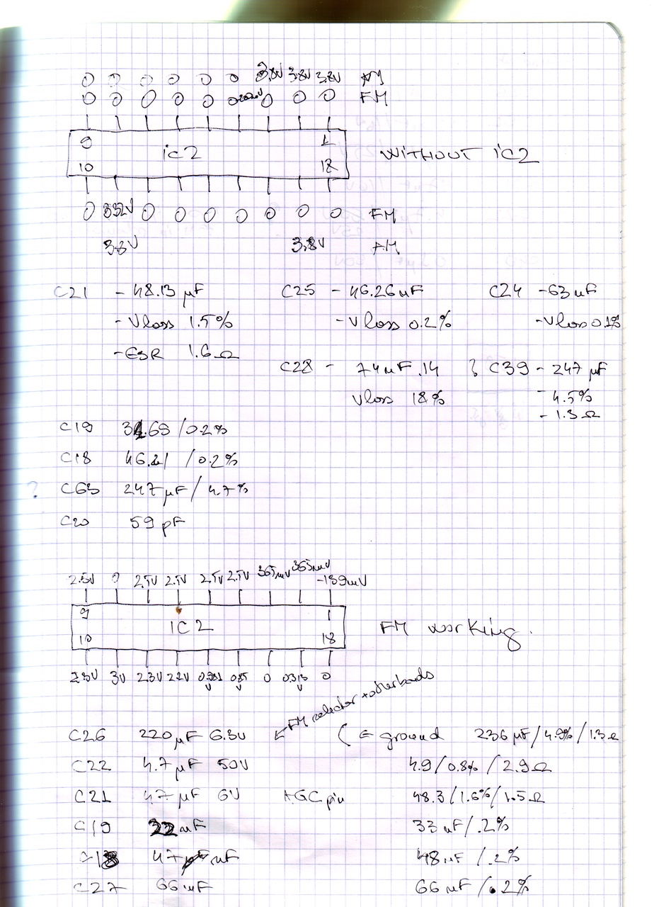
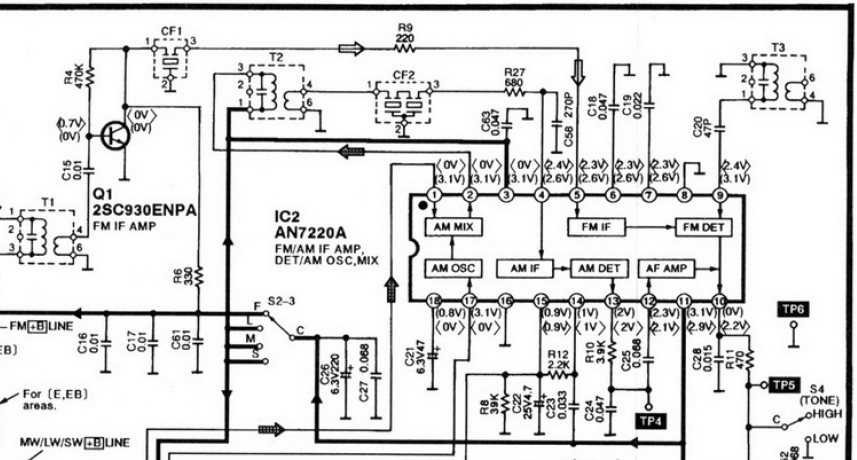
I measured also the voltages on the AN7220A chip:
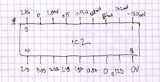
Most of the voltages looked OK compared to the schematics – however, pin 5 and pin 6 of AN7220A were too low compared to the suggested 2.4V in normal FM working conditions. Voltages on the transistors looked fine, thus, the only thing I could think of was that the AN7220A is damaged and decided to order a spare one from ebay.
Getting closer
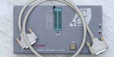
While waiting for the AN7220A to arrive, I decided to de-solder existing one:
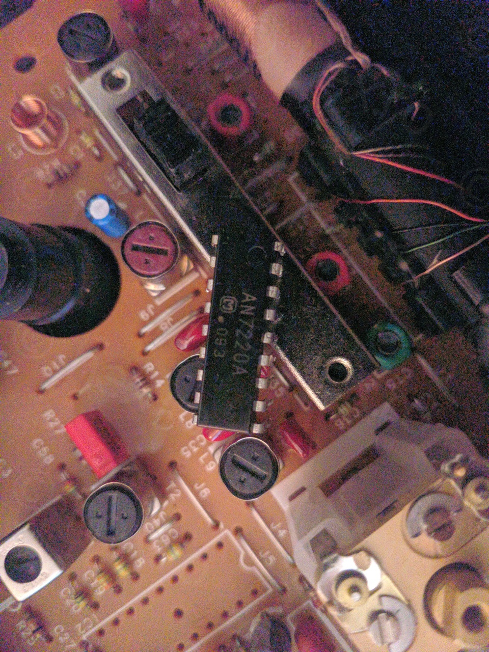
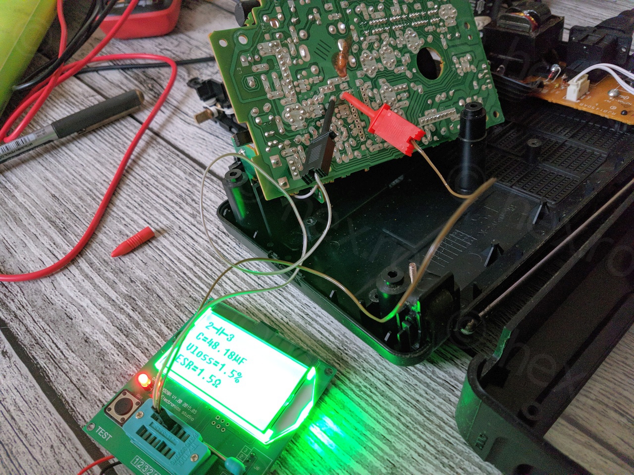
Was still not convinced the IC is broken, I figured I should install a small socket so that I could swap old IC with new IC and continue measurements. With the AN7220A desoldered, some capacitors could be measured, but everything seemed OK with the simple measuring device I was using:
The new IC has arrived, but unfortunately the radio was still not working.
While loosing hope that the radio can be fixed, halfway while pulling the IC from the makeshift socket, the radio came alive!!
After a little bit of fiddling around, there was indeed a position in the socket, with the IC not fully pressed in, where the FM was working properly. Very clear sound, loud, finding many stations, but why ?! Not only this, but the voltages now looked correctly (for FM):
The most intriguing pin was PIN 6 of AN7220A that was only connected to a ceramic capacitor (C18). In the ‘good’ sitting position it had 2.4V, but with the IC properly fitted into the socket, it was having only 0.4V … so something inside the IC was actually pulling it down to 0.4V or something external (through the IC) was not lifting it to 2.4V – as its only connection, C18, was directly to GROUND. Hmmm.
I figured something else external to the IC may actually short it and force it to drop the voltage on PIN 6 or otherwise not lifting it up to 2.4V. Looking again at the schematic…
Troubleshooting
…it started to become clear that pins 10-18 do not exhibit any problem – voltages were right; pins 1-3 don’t matter as they were 0V correctly; the only ones that I have to focus on were pins 4-9. Out of these, the pin 6, 7, 8 (ground) and 9 were connected to passive components and those tested OK and more, with the AN7220A half pushed into the socket, the pins were showing correct voltages. So that left me focusing on pin 4 and pin 5. On closer inspection, PIN 5 is carrying signal from the FM front-end (AN7205) so it must work.
That left me with a single choice to investigate, PIN4, the input to the AM-IF stage inside the AN7220A IC! But why would AM influence the FM ?!?!? Very puzzled, I decided to desolder one pin of R27, the one between CF2 and R27. And … magic! The radio came alive 🙂
The Fix
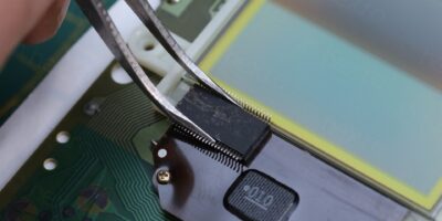
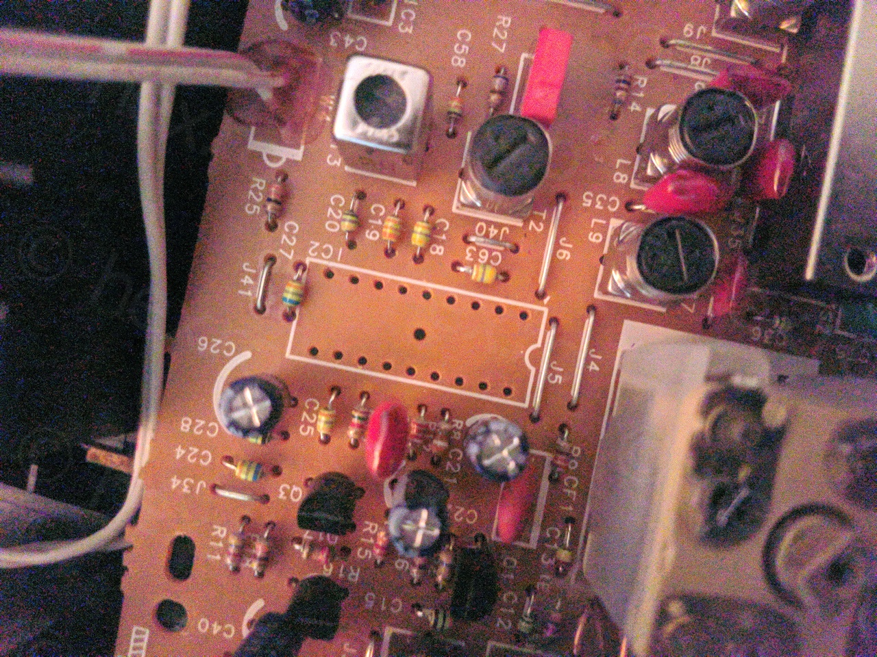
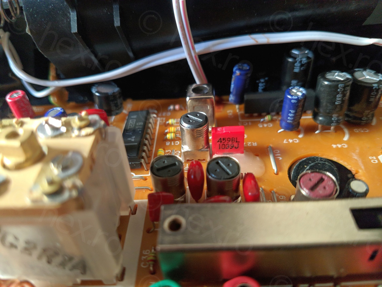
I identified the faulty component as being the Ceramic Filter CF2 (a 459kHz pass-band filter), the red one marked 459BL 1039J in the picture below:
Unfortunately, it was impossible to find a replacement … on ebay, there are some 459kHz ceramic filters but not with the same pin-out. Out of ideas, and knowing that AM is not usable in Belgium anymore, I decided to just install a 455kHz ceramic filter that I had available (I have ordered some as I wanted to play with the new Siglent 1104X-E oscilloscope / Siglent SDG2042X signal generator that I was planning to buy).
I figured the slightly left-shifted band filter will still allow the radio to properly work on FM, the only drawback would be that AM stations (again, nonexistent in Belgium) would sound a little weaker than normal. But since it would never be used on AM, it is a good compromise fix. Here’s a photo with the new 455kHz (yellow) pass band ceramic filter installed:

I also left the new IC in, instead of the old one. I have changed the CapXon capacitors around AN7220A with equivalent Rubicons / Nichicon caps. One thing that was odd, capacitor C22, which, in the schematic it appeared rated for 25V but the installed one was 50V. Not a problem, just I figured I should mention it.
Re-assembling the radio
I glued back the broken threaded pole using J-B Weld, while making sure beforehand that I enlarged the threaded hole so that the screw doesn’t put so much tension on it.
I have also applied silicone grease on all the screws before screwing them in, hopefully to prevent other cracks in the future and making it easier to take the radio apart again should it be necessary. The initially broken threaded held up properly!
Results
FM works perfectly, and LW is usable (tuned to BBC Radio 4 @198 kHz) – volume had to be turned up to level 5 to compensate for the lack of a 459kHz pass band filter.
Tuning LED also works.
Fish shmuel
Nice work , looking to get idea on my rf1130 panasonic, no fm,