Introduction
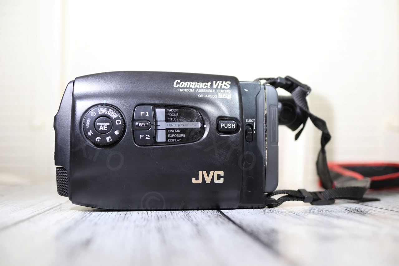
This is the second Miyota 2400-58 that I find in a JVC camera, but as opposed to the first one that came from a JVC GR-AX400EG, this one came from a JVC GR-AX200EG.
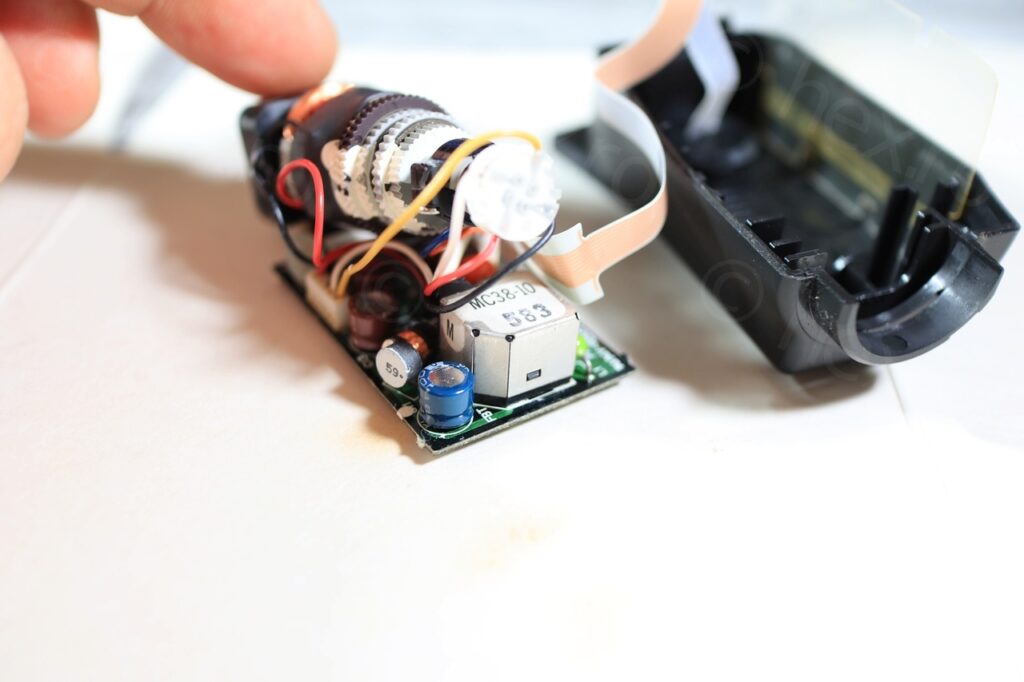
Not only that, but the driver boards look almost identical in component layout, with slight changes to the silkscreen.
Camera tear-down
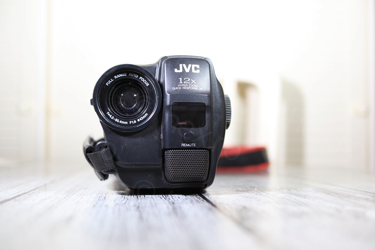
The JVC GR-AX200EG was up for sale at a flea market. It looked clean and I was convinced I had already had opened an identical one. Only at home I realized that there is a slight difference in the camera models.


It also came with a battery, but the battery will go directly to the Recypark:
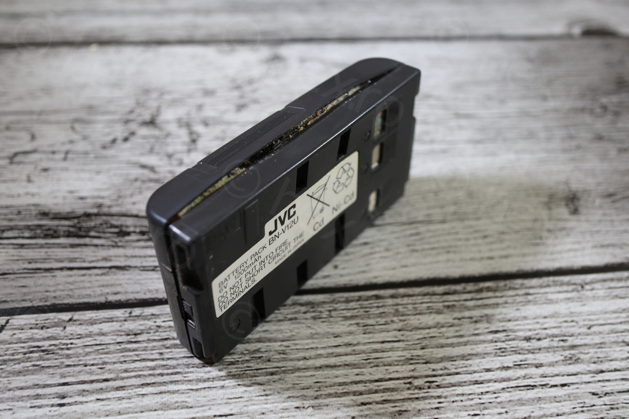
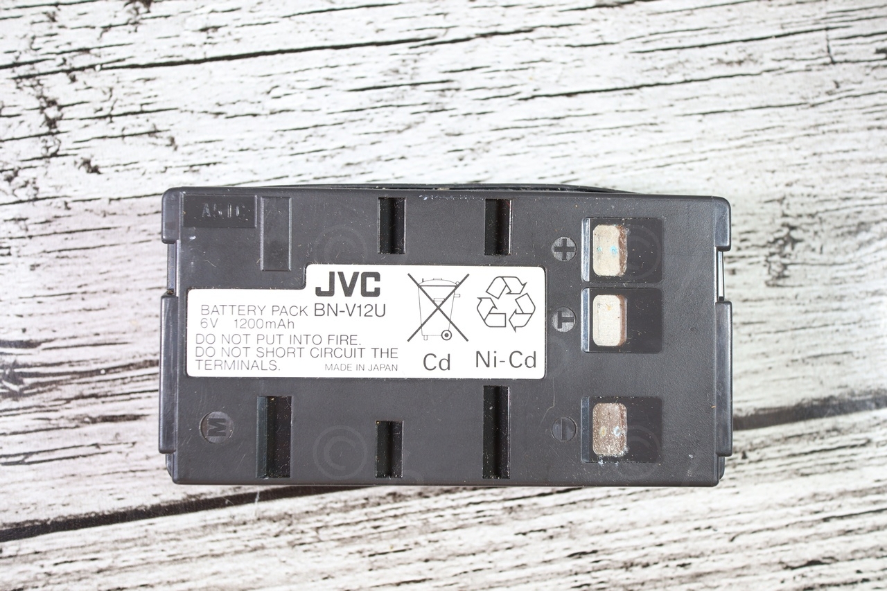
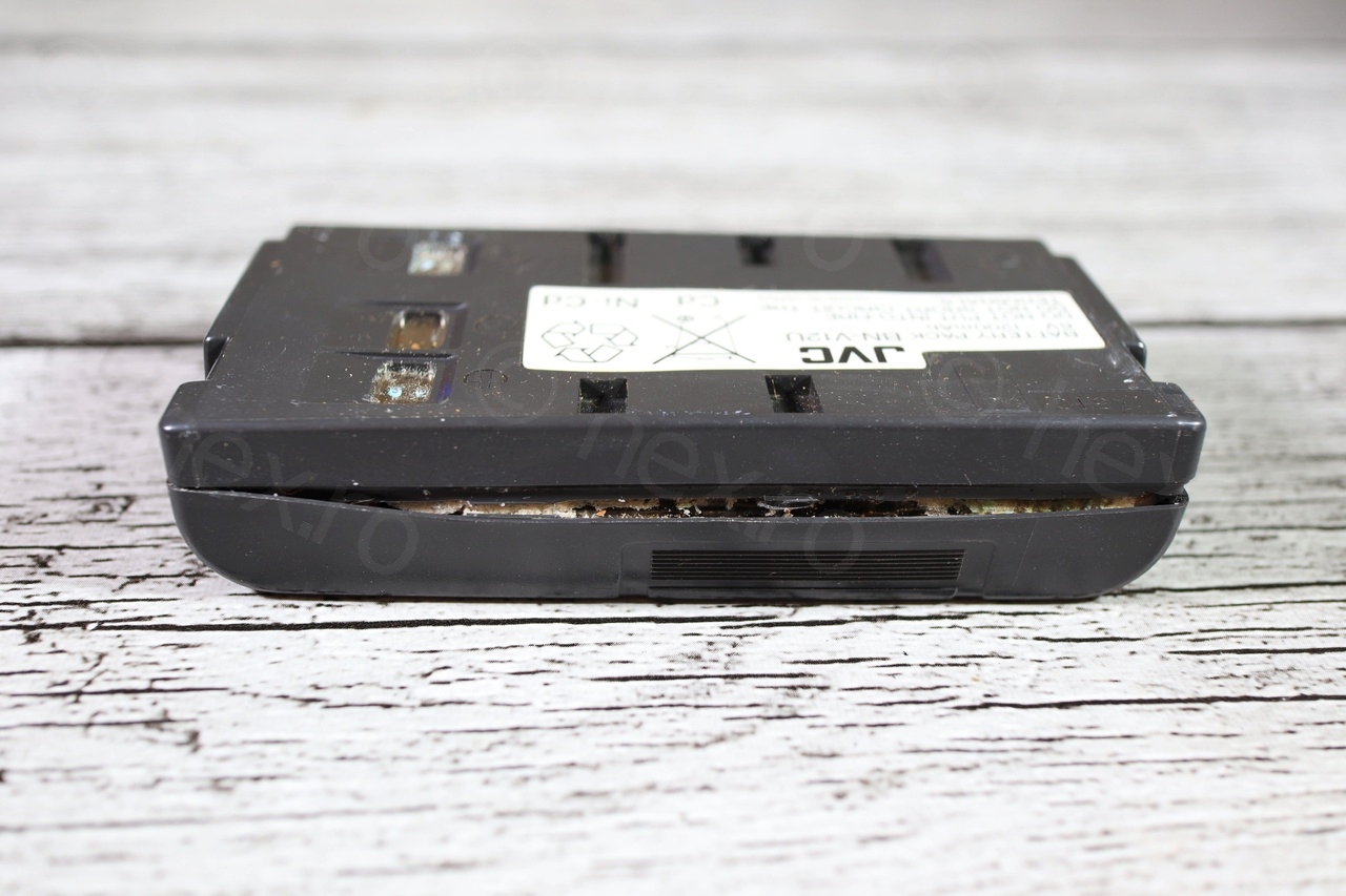
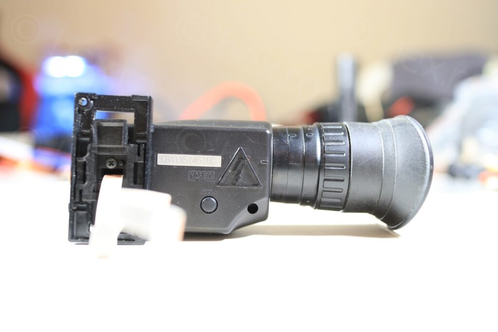
The battery label is important, as it already gives a maximum voltage to power on the CRT inside the Electronic View Finder unit. In this case, probably up to 6V and a little more.
I did try to power the camera with 6V independently, but except the ON led coming on for a brief second, nothing seemed to work.
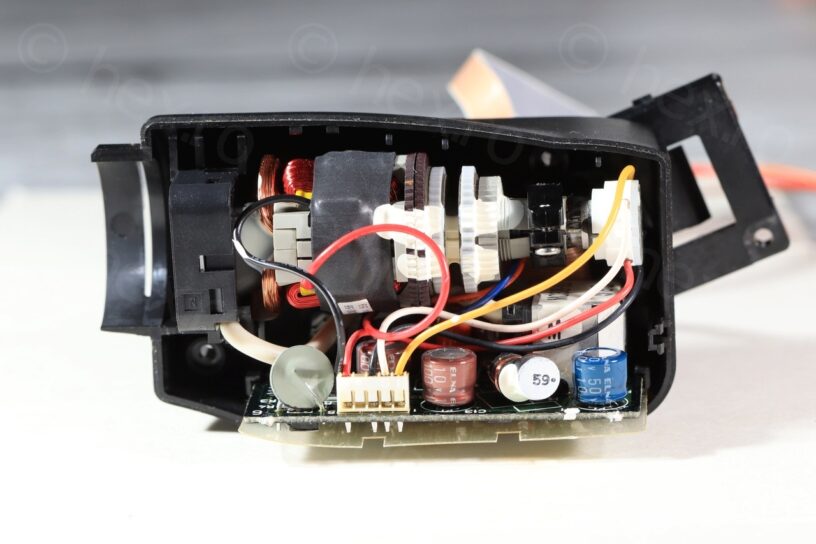
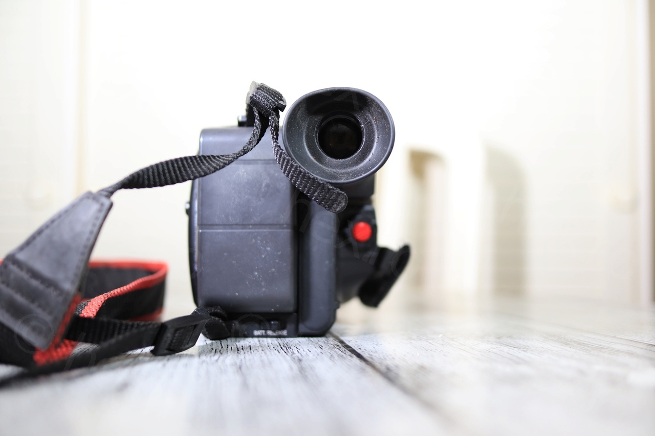
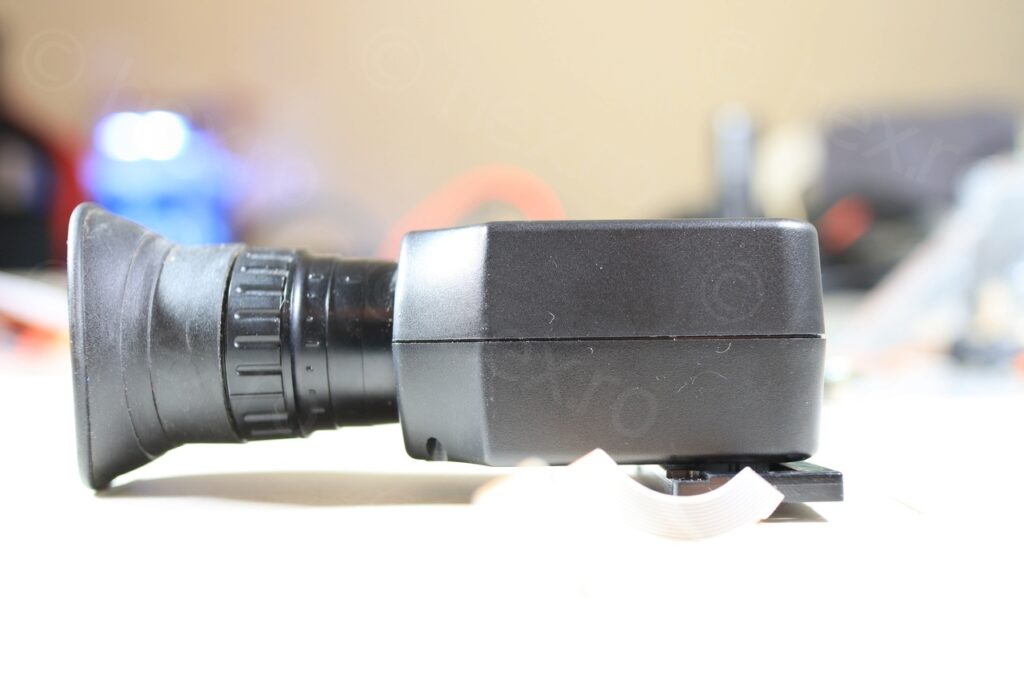
During tear-down, I recalled the struggles to open the JVC GR400EG model. Can’t seem to get to the EVF unit without taking the whole camera apart starting from the tape door and working my way through to the other side:

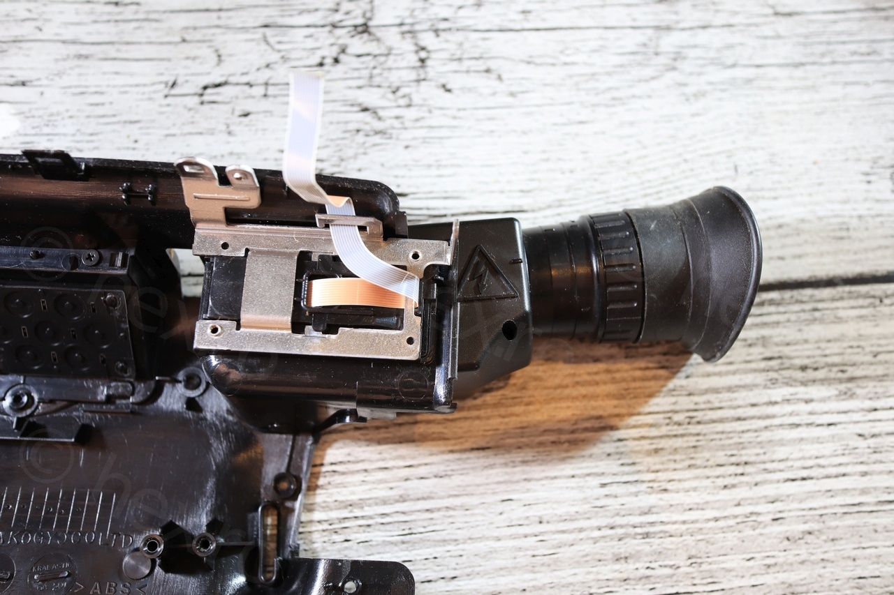
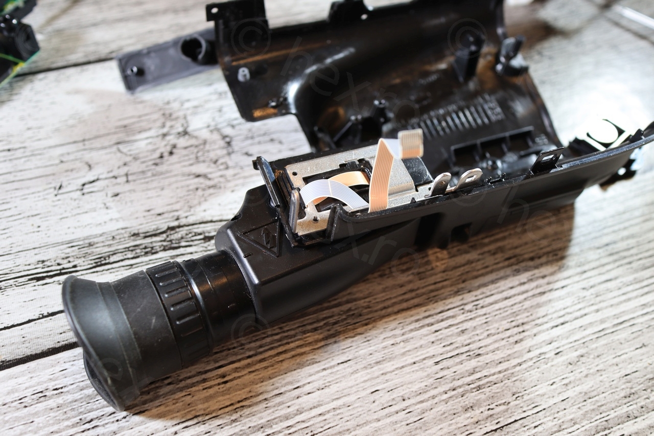
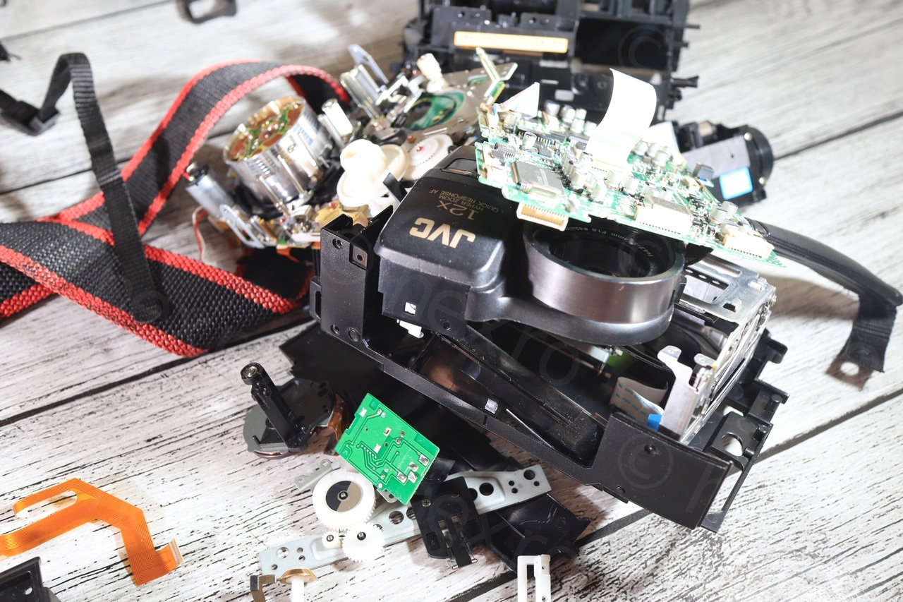
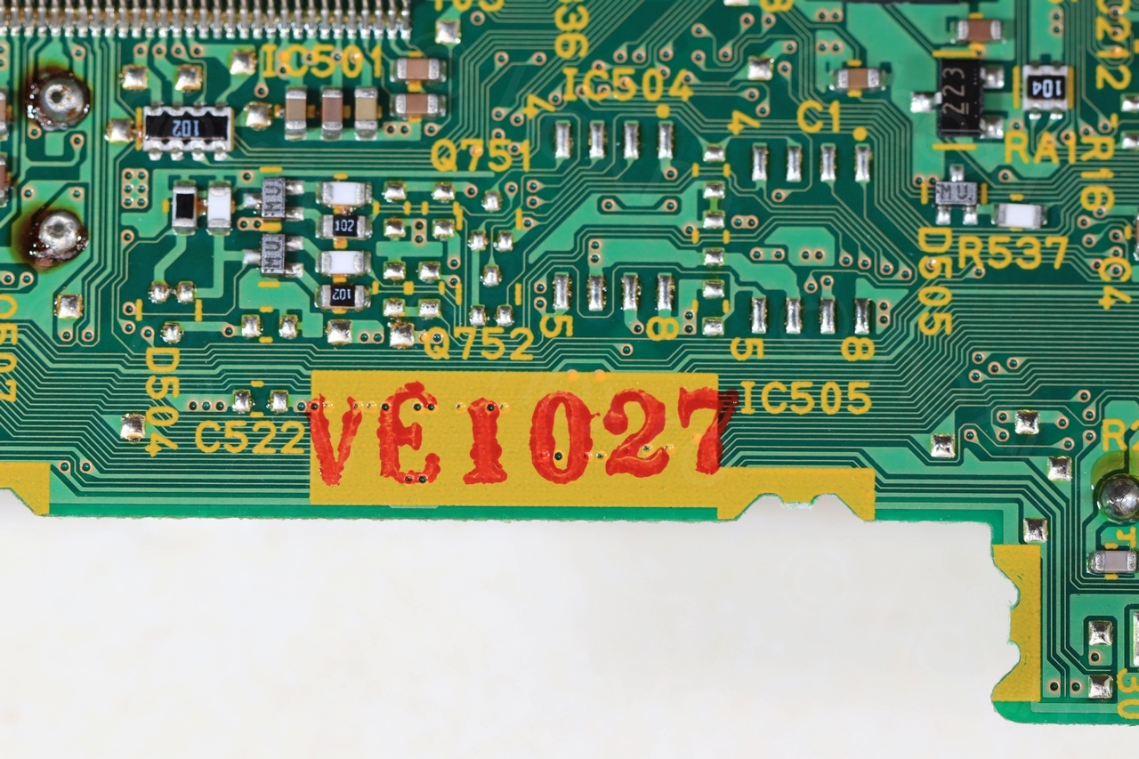
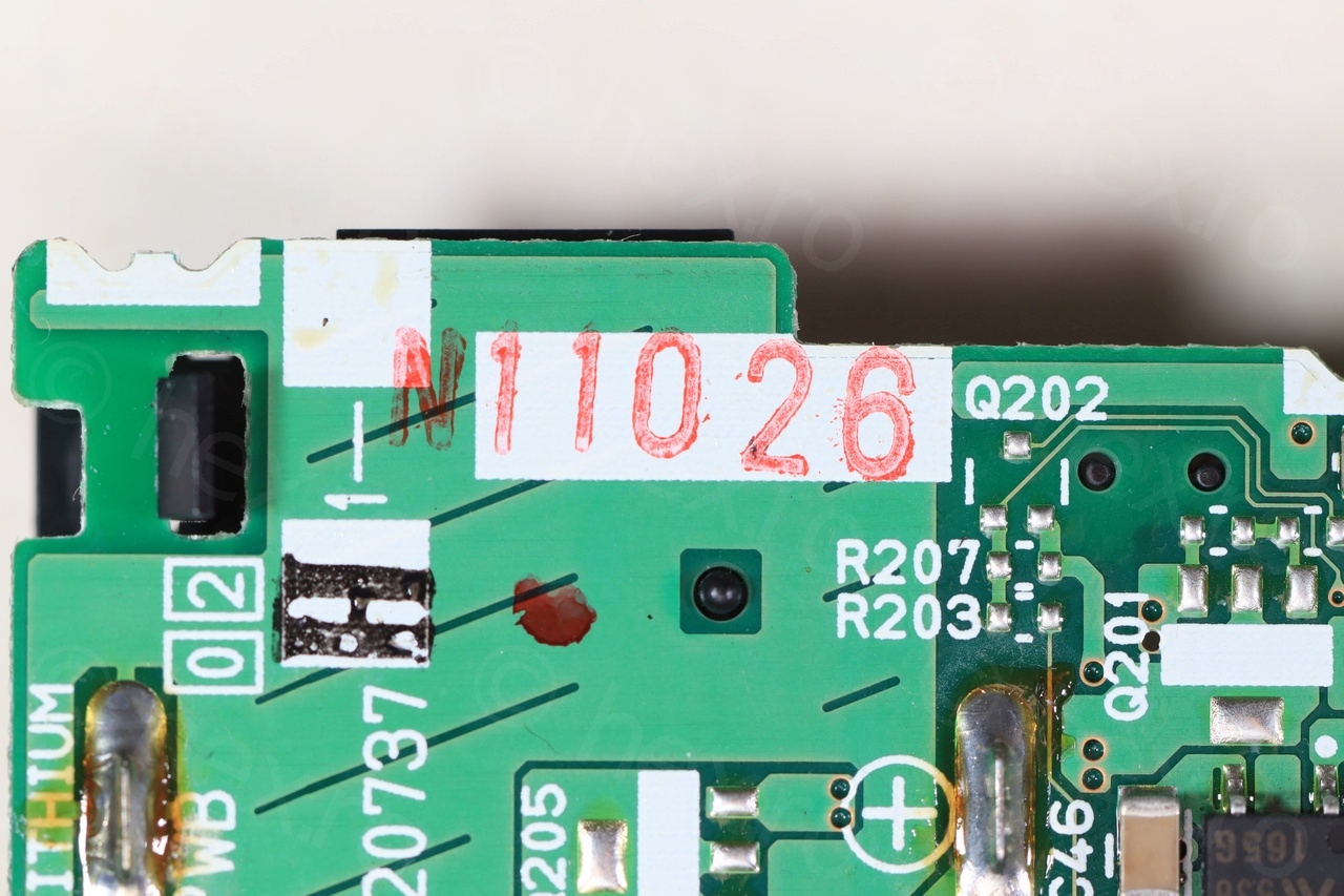
Interestingly, I encountered some texts written on the motherboard(s). Used to think these may signify date codes, but I guess they don’t (as you can see from the small grid inside the plastic skeleton (last photo):

CRT
Finally got the CRT freed from the camera body:
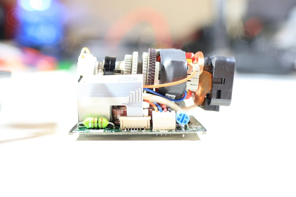

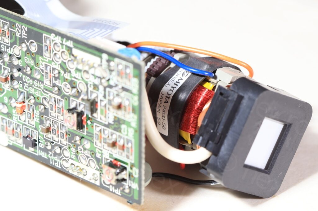
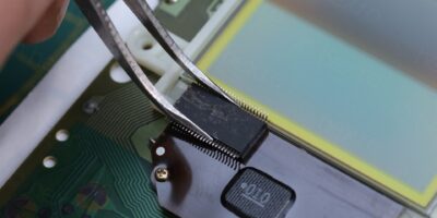
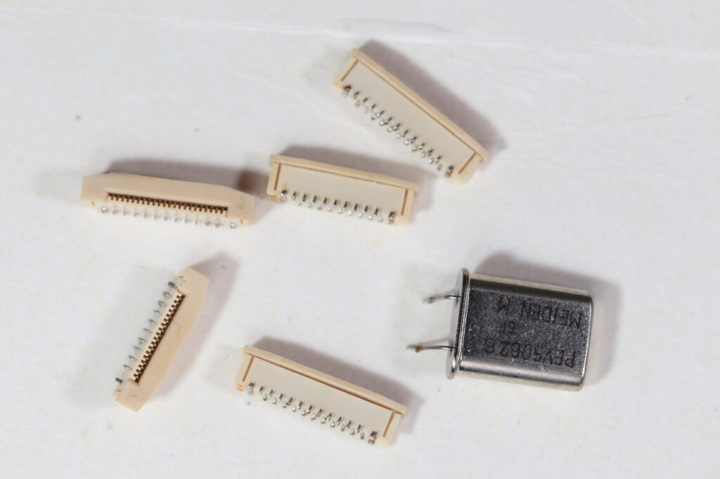
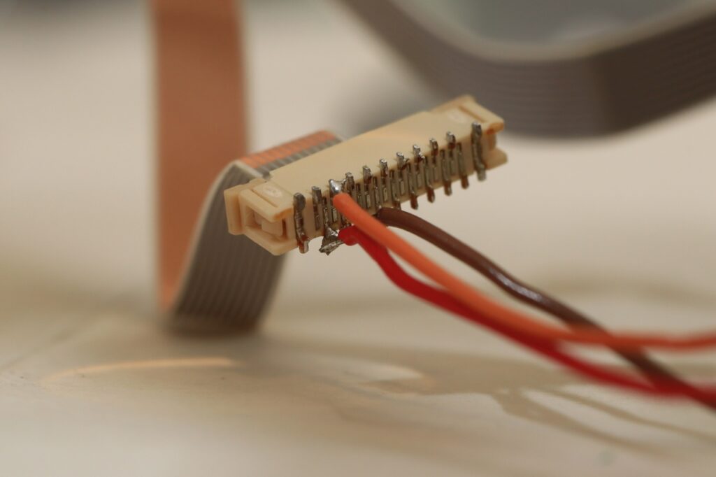
Identifying the signals is easy as long as you de-solder one of the connectors from the motherboard, as working directly with the flat cable is tedious.
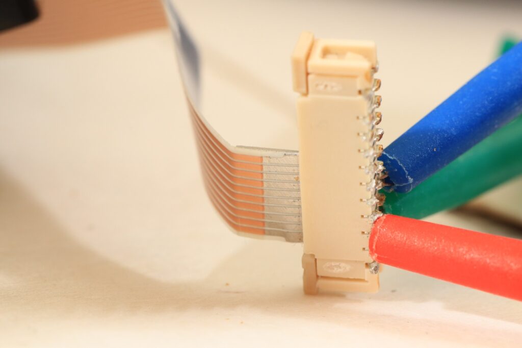
GND is easily picked up from as the shield of the Fly Back Transformer.
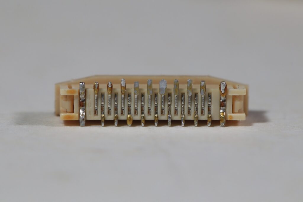
I used to search for the VCC pin by starting from the schematic of the BA7149F chip, specifically its pin 2. However, the schematics also show that the FBT has a VCC connection, and once I have identified the VCC from the Pin 2 of BA7149F, I was curious to see which FBT pins are also connected to VCC. I found that pin 3, 4 and 5 of FBT are connected to VCC.
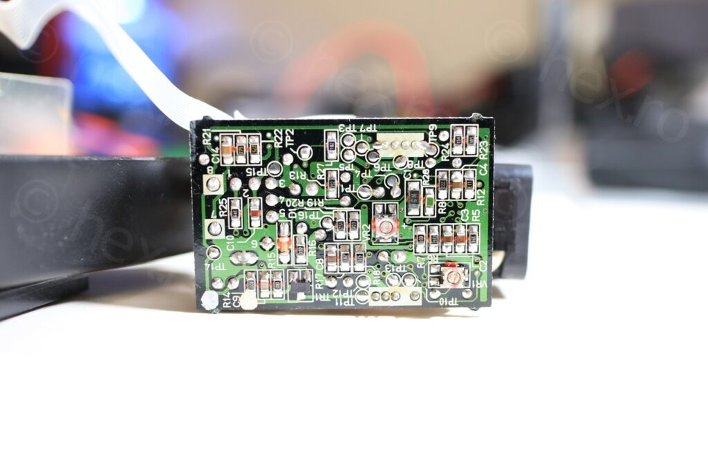
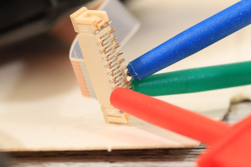
Video IN was a little more tricky to locate, but with the Vcc/GND identified – it was just a matter of trying out the other 3 pins … Video IN is present on the 2nd pin of the connector (in the photo above), in between GND and VCC (but opposite row, if connected as above of course).
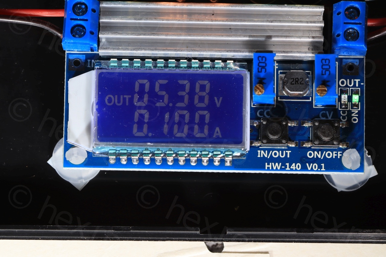
I was able to obtain the sharpest image when powering it with ~5.4V, and observed that the sharpness also goes away very quickly if you go more than 0.2V either way.


Of course, I had to play Manic Miner. Not that I like replaying the first level on and on, but it gives me an opportunity to see if there are other weird image shifts or ghosting present:
Hope you found it interesting 🙂
NikNak
Great site! I have 4 mini CRTs and thought I probably had too many, but now I see your site and I’m quite pleased, I obviously don’t have enough!
I’ve just ordered more from E-Bay!
BTW Your notes are very useful, they have saved me some time with figuring out the pinouts – appreciated.