


I decided to collect mini CRTs after seeing a blog post about one of them long time ago. As CRTs are going away, I figured it would be nice to own few, as a reminder of the old times. The obvious source are old video recorders that are sold at flea markets, and I did find some.
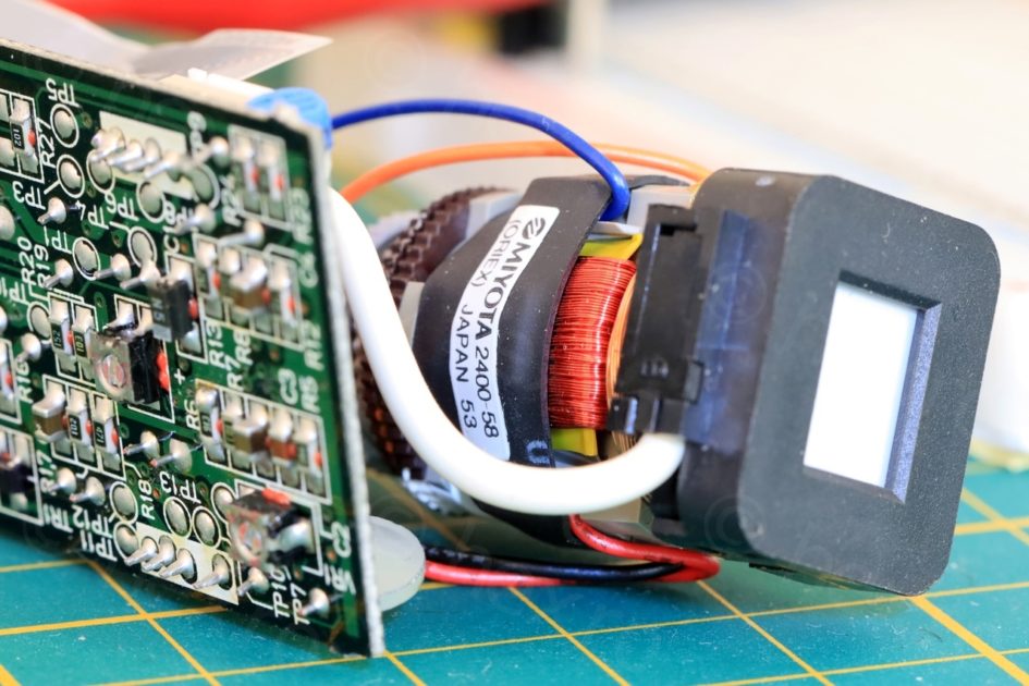
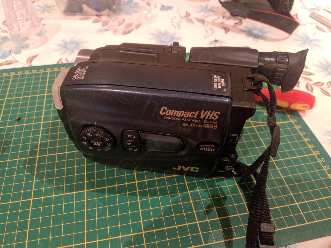
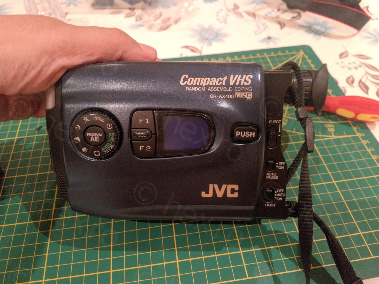
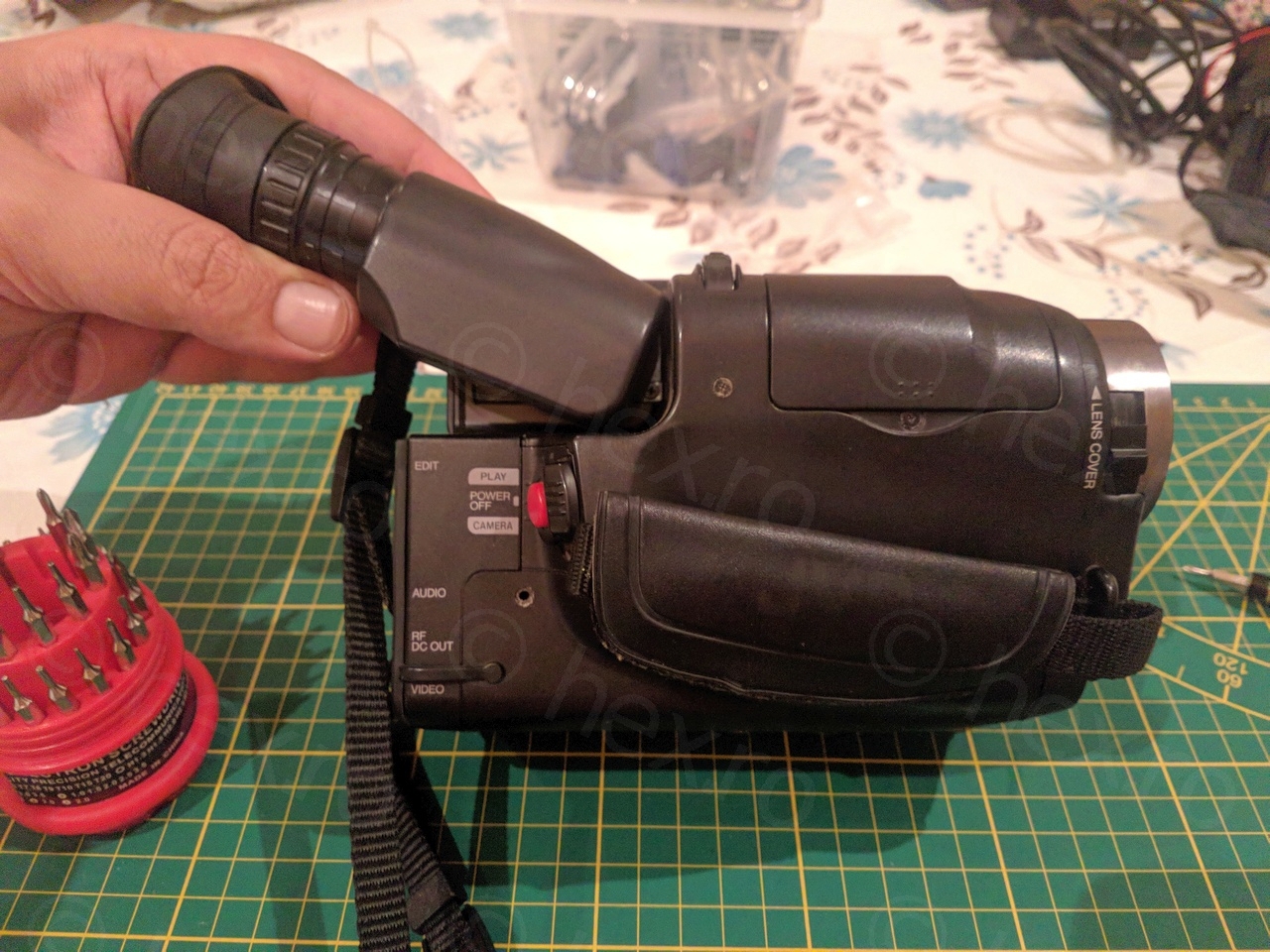
Miyota 2400-58 came from a JVC GR-AX400EG camera.

Introduction
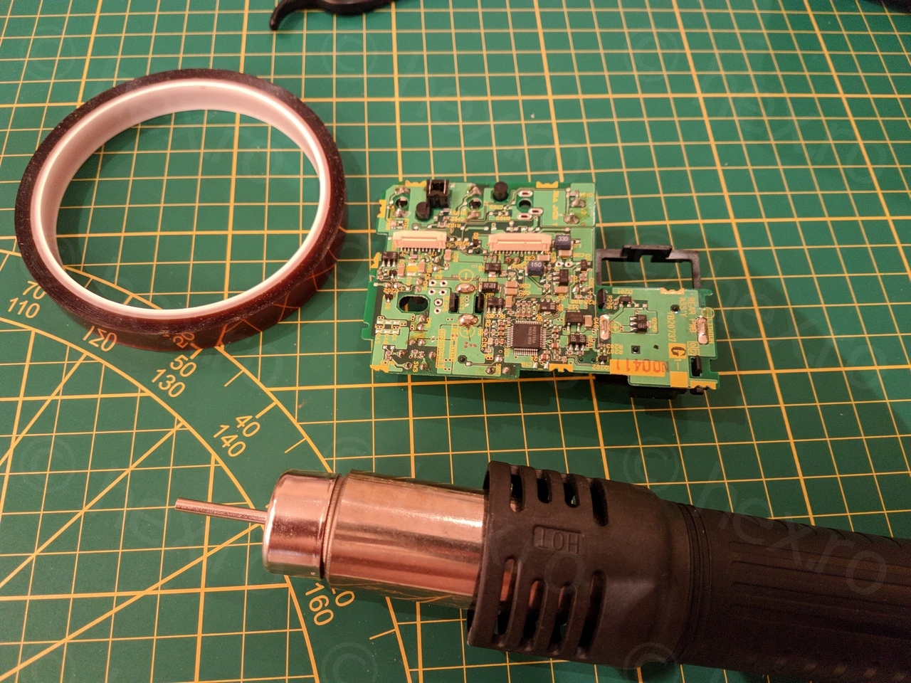
The viewfinder contains both the CRT as well as the control board. As others figured out already, the camera sends some signals to the CRT control board (besides the 5V VCC/GND) and should you want to get a video being displayed, the challenge is then to locate the composite Video In pin on the control board.
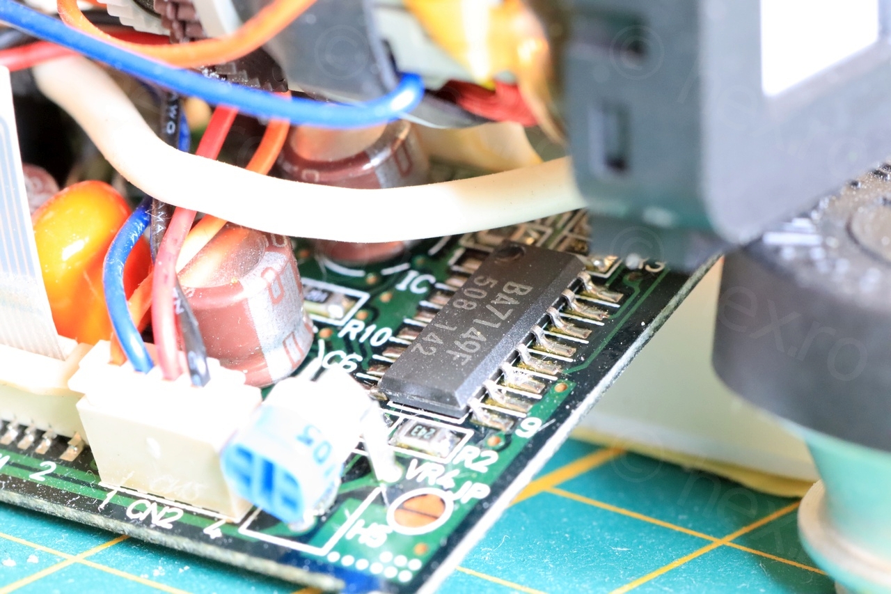
Control board is connected to the camera’s motherboard using a 10 pin flat cable. To help with tracing down I have used the multi-meter in continuity mode and luckily I was able to easily find the schematic for the IC that is central to the control board (BA7149F).
Interfacing
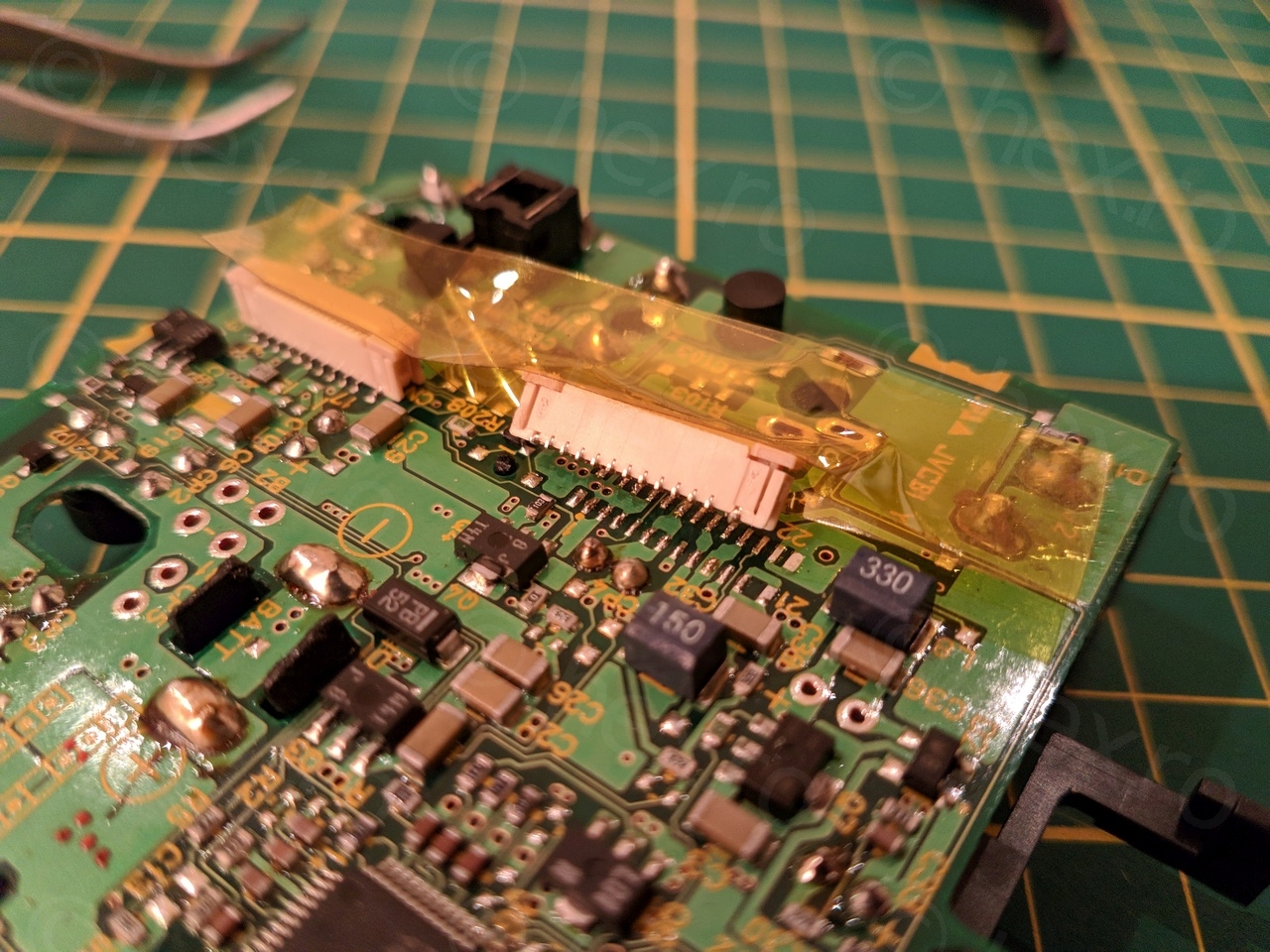
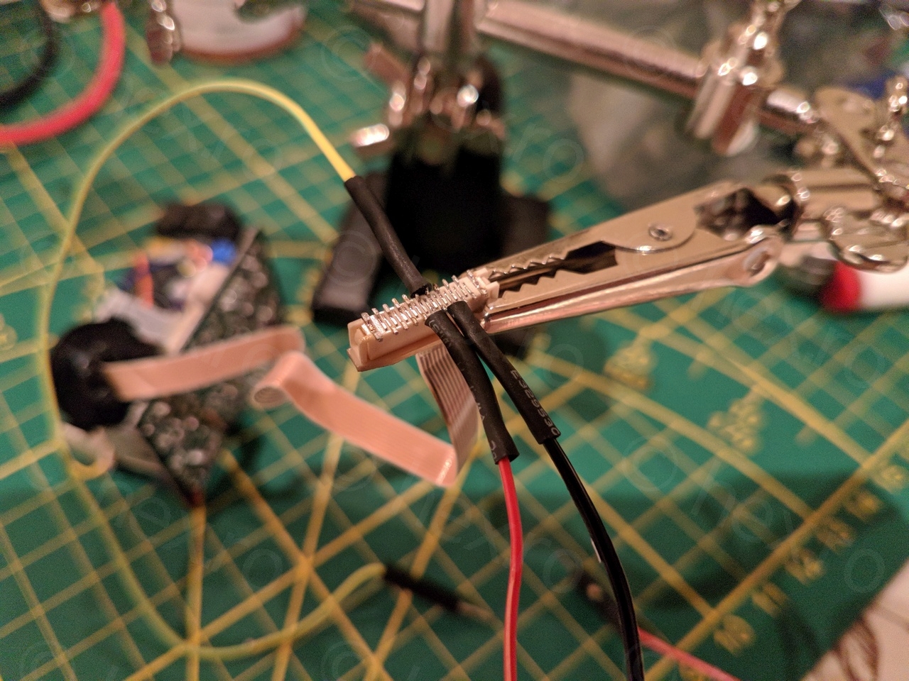
The first problem was how to send the signals to the board. There is an easy solution to solder wires directly on the control board, but I find this too intrusive… it works, but there is already a connecting cable going to the board, and what if it won’t fit properly back into the viewfinder housing ?
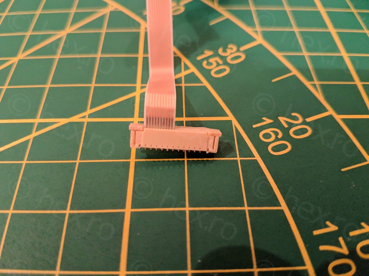
However, soldering directly onto the flat cable is not possible as it will melt the plastic. So I decided to scavenge some connectors from the motherboard itself to use them as an interface to the flat cable.
Tracing the signals
There are three signals to be traced, VCC, Ground and the Video IN signal. Locating the VCC and GND were the easiest, and Video In took a bit of tracing using the meter in continuity mode.
While I could use some known tricks to spot the GND and VCC (for example, most electrolytic capacitors are hooked between VCC and GND), the most difficult was to realize that most probably JVC did follow the BA7149F’s Application Example:
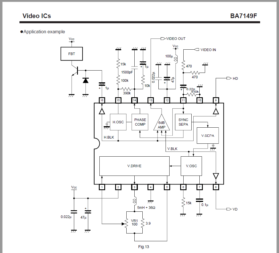
As you can see:
- VCC is hooked directly to PIN2
- GND is hooked directly to PIN10
The most difficult to locate is the Video IN signal, which doesn’t have a direct path to the IC – it passes through a resistor divider (470 ohms each) and then through the 0.22uF capacitor before reaching PIN 11 of the IC. With some trial and error (using the multi-meter in continuity mode), I was to locate the + pin of the 0.22uF capacitor (C4 on the silk screen, directly connected to PIN 11 of the IC), and following the – pin of the identified capacitor, find the two resistors (R27 and R12 on the silk screen) and see which one _does not_ connect to GND (R27 has the Video IN signal and is the closest to flat cable connector CN1; R12 is the one that goes to GND).
On connector CN1, the pins carrying the signal are:
- VCC (5V) goes on PIN2
- GND goes to PIN 6
- Video IN (composite) goes to PIN 3


Testing Setup
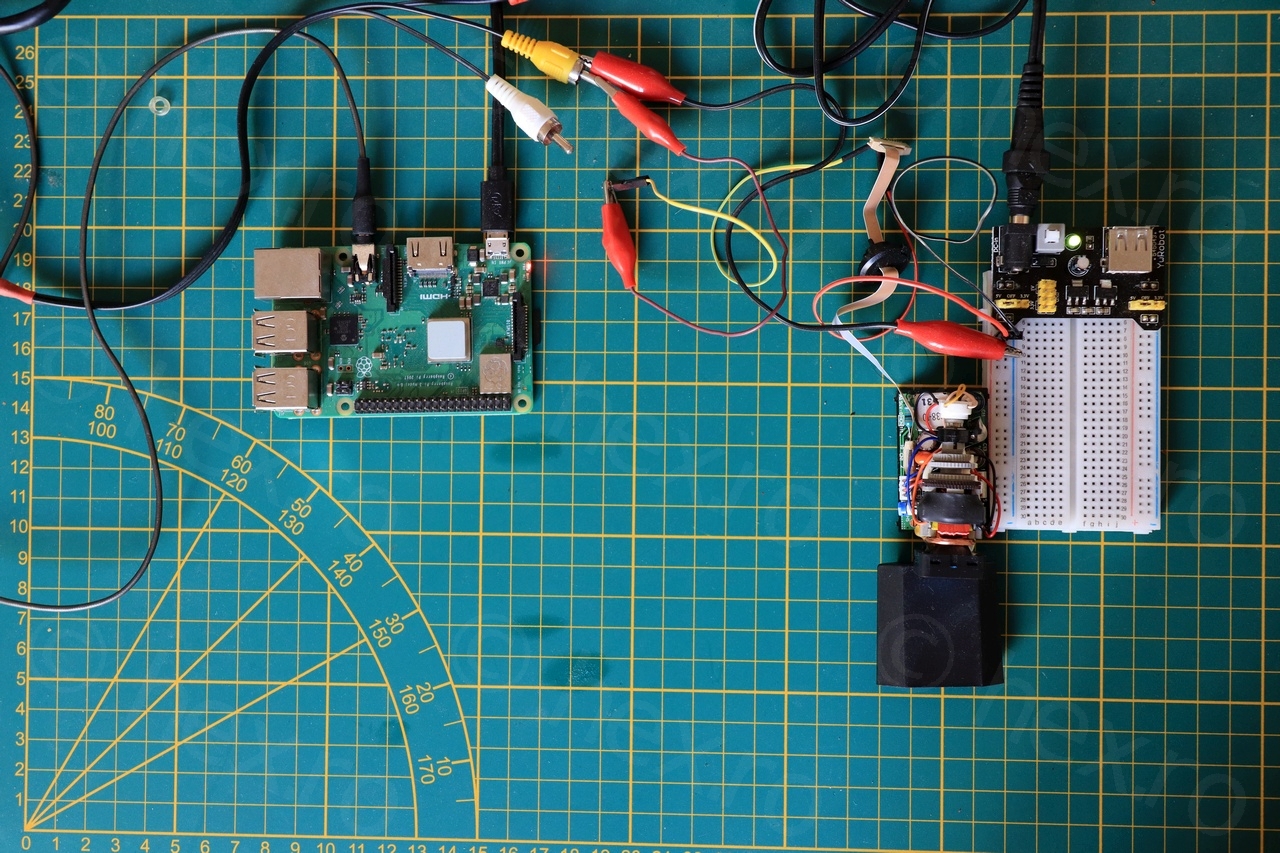
To generate a Video IN signal, I had some spare RPi3B+ board which I modified its config.txt file to generate Composite Output on the 3.5mm jack. Also, since I was driving such a small screen, also opted out for a lower resolution (240p).
There are many tutorials online on how to do that – for example: https://www.raspberrypi.org/documentation/configuration/config-txt/video.md and you will also need a special cable that you can make yourself (or buy ready made).
Results
Conclusions
A very fun project 🙂 albeit a little useless (or at least for now, I have no idea what to do with the CRT). Initially I thought I could 3D print a case for the little CRT, but on the other hand – I am afraid it may melt the case should it get hot.
It is not very sharp on close inspection (macro shot) but it looks very sharp when you look at it with the naked eye. I do have more cameras to take apart, so please stay tuned!
Justin
Are you into magnetrons or vacuum tubes?
viulian
I would say … initially I needed 1 or 2 for an Arduino project. But then it became a challenge, some cameras had complex wiring for the EVF units. Then I found larger mini CRTs and they were interesting too. Now … I rarely buy, I still have few to take apart though 🙂