


Introduction
This mini CRT came from a Sony CCD-TR8E camera. Although I got the CRT to work, the image is not stable – there is still a problem on the driver board (even after replacing a leaked capacitor). More below.
Camera
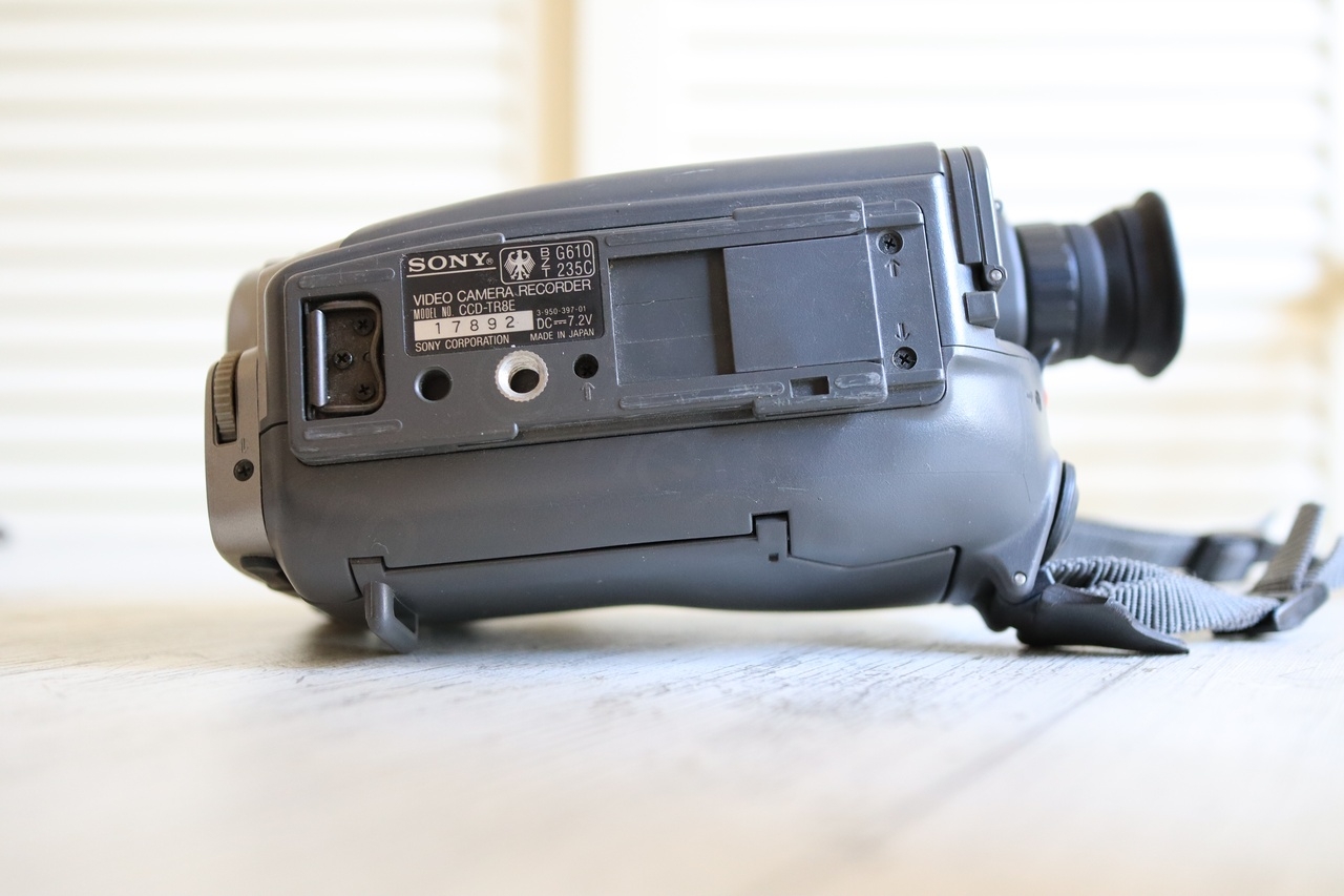
The camera looked nice from outside and did not have too many scratches, it was well taken care of. Sold with Sony HSA-V500 Handycam Station, I decided to buy it.
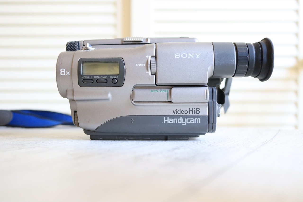


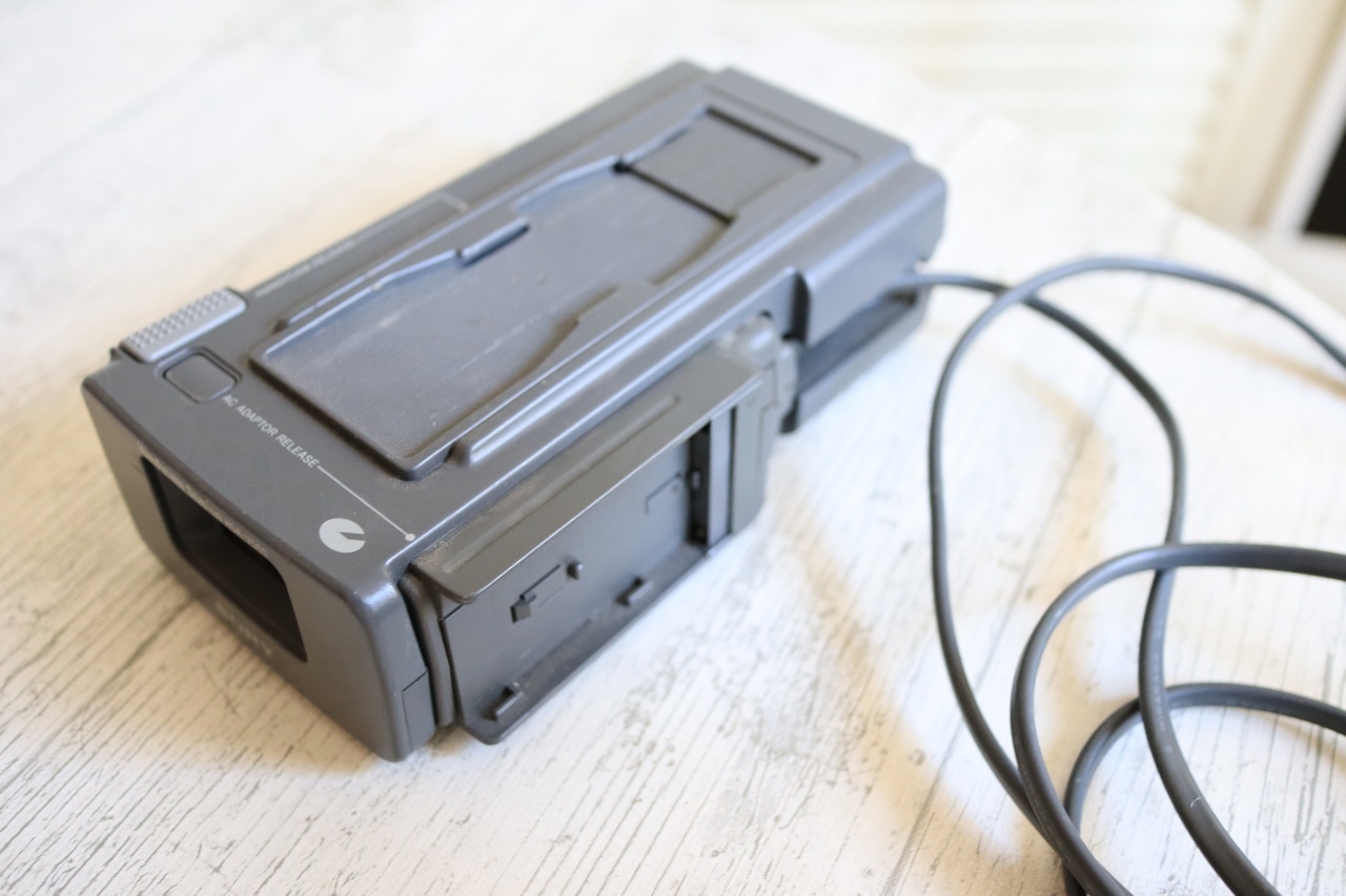
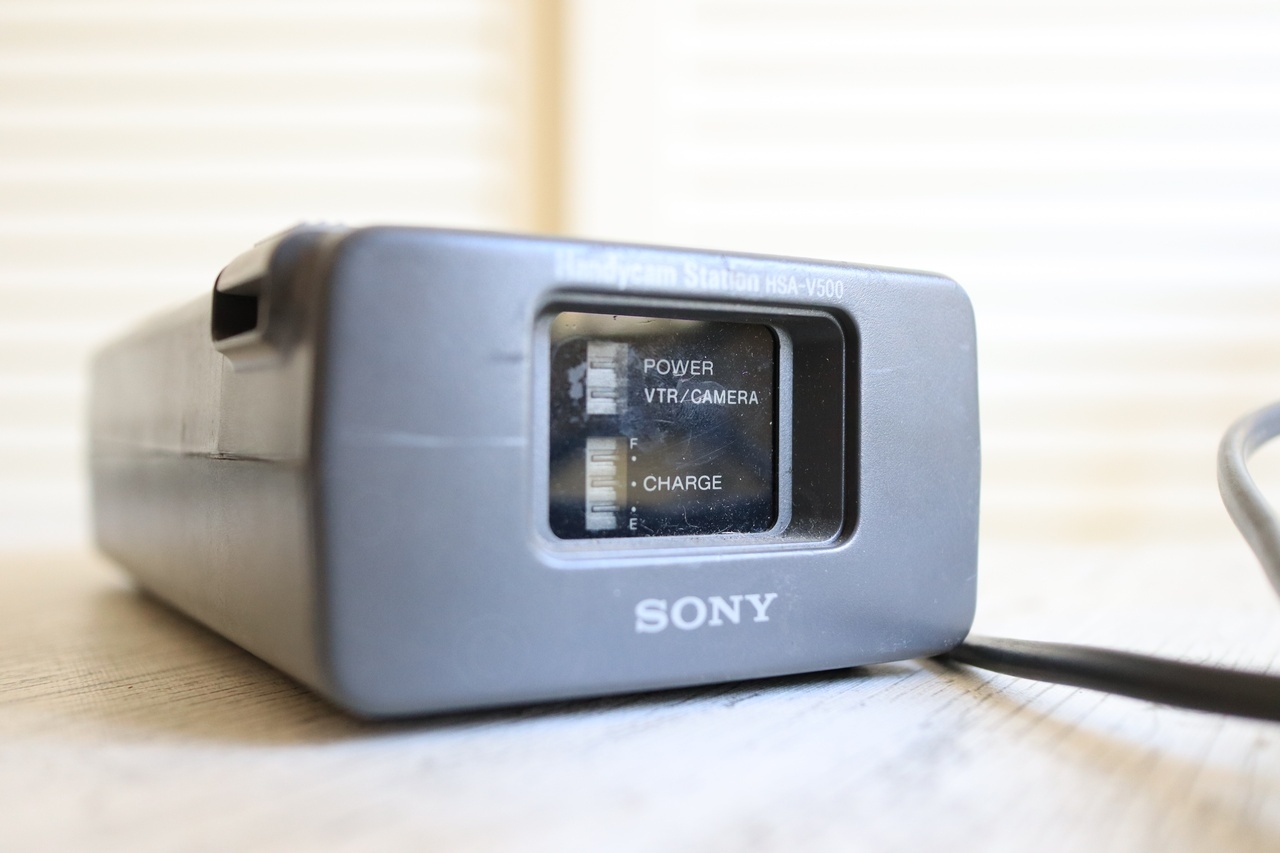
Its dock was a nice addition – it seems to permit charging both the camera as well as an additional battery, while offering the Video Out signals too.
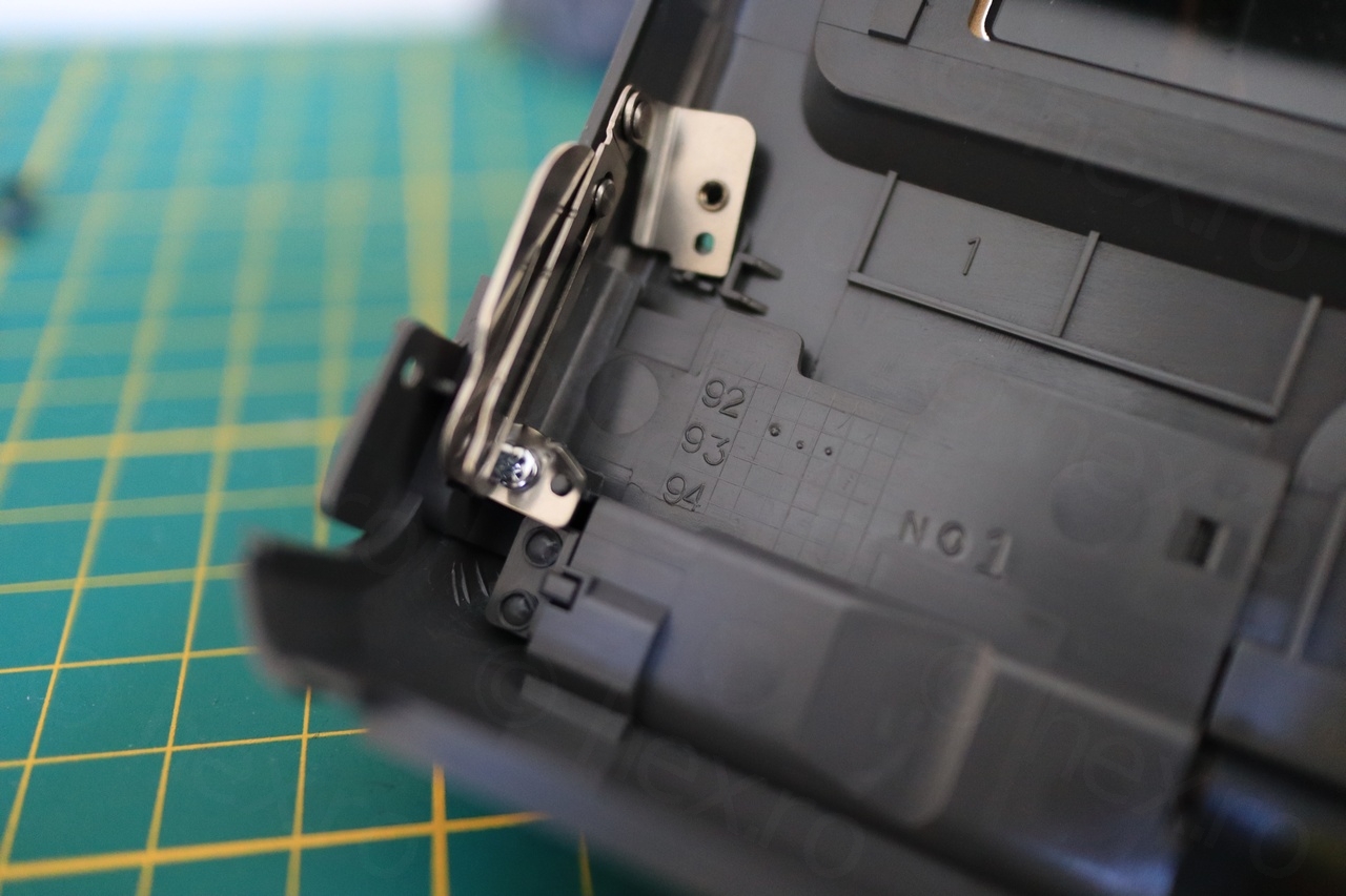
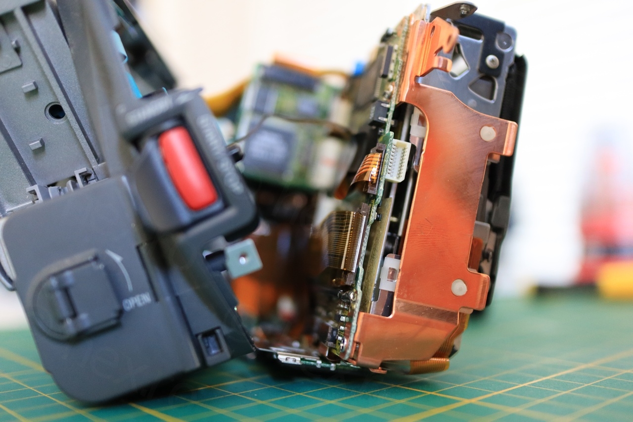
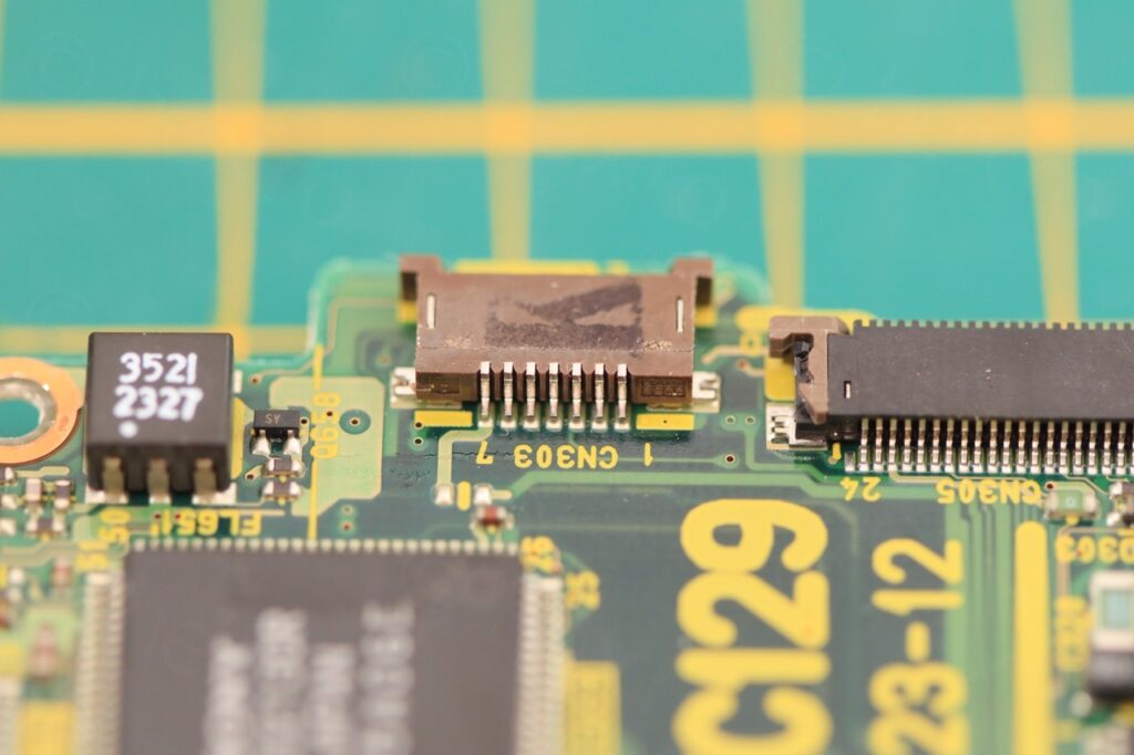
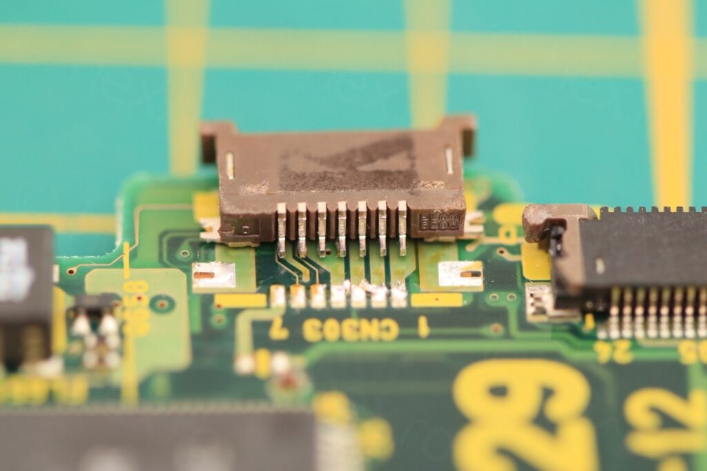
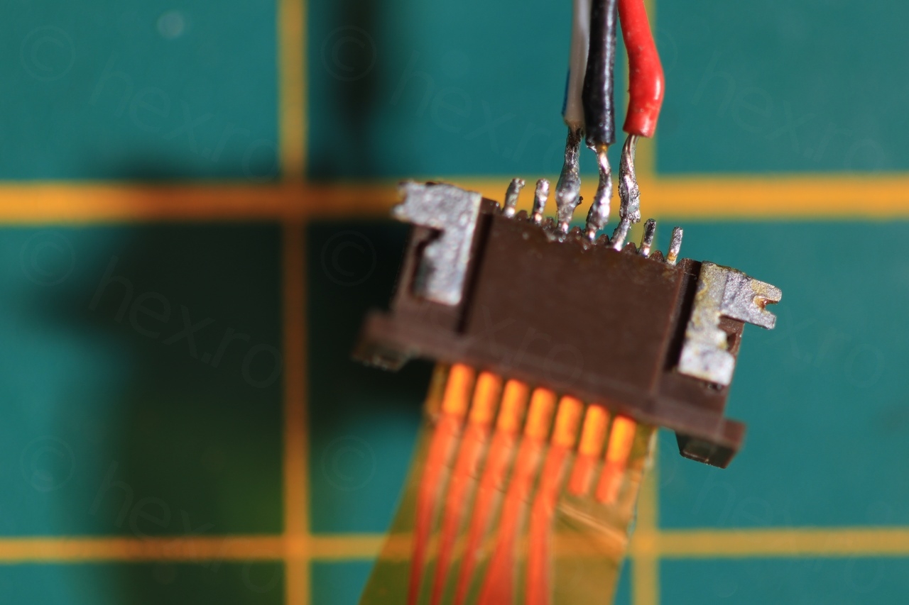
Getting into the camera was very easy, not too many screws. It seems Sony went for a flat cable to drive the EVF unit. This is tedious to work with when salvaging the CRT, even if I de-solder the connector from the motherboard it is still hard to solder some wires to that connector (the wires that I would use to send power and signal to the EVF unit).
Camera made in Aug 1992. While opening the camera was easy, taking the EVF unit out was difficult as it required taking the battery compartment out to get to the last two screws.
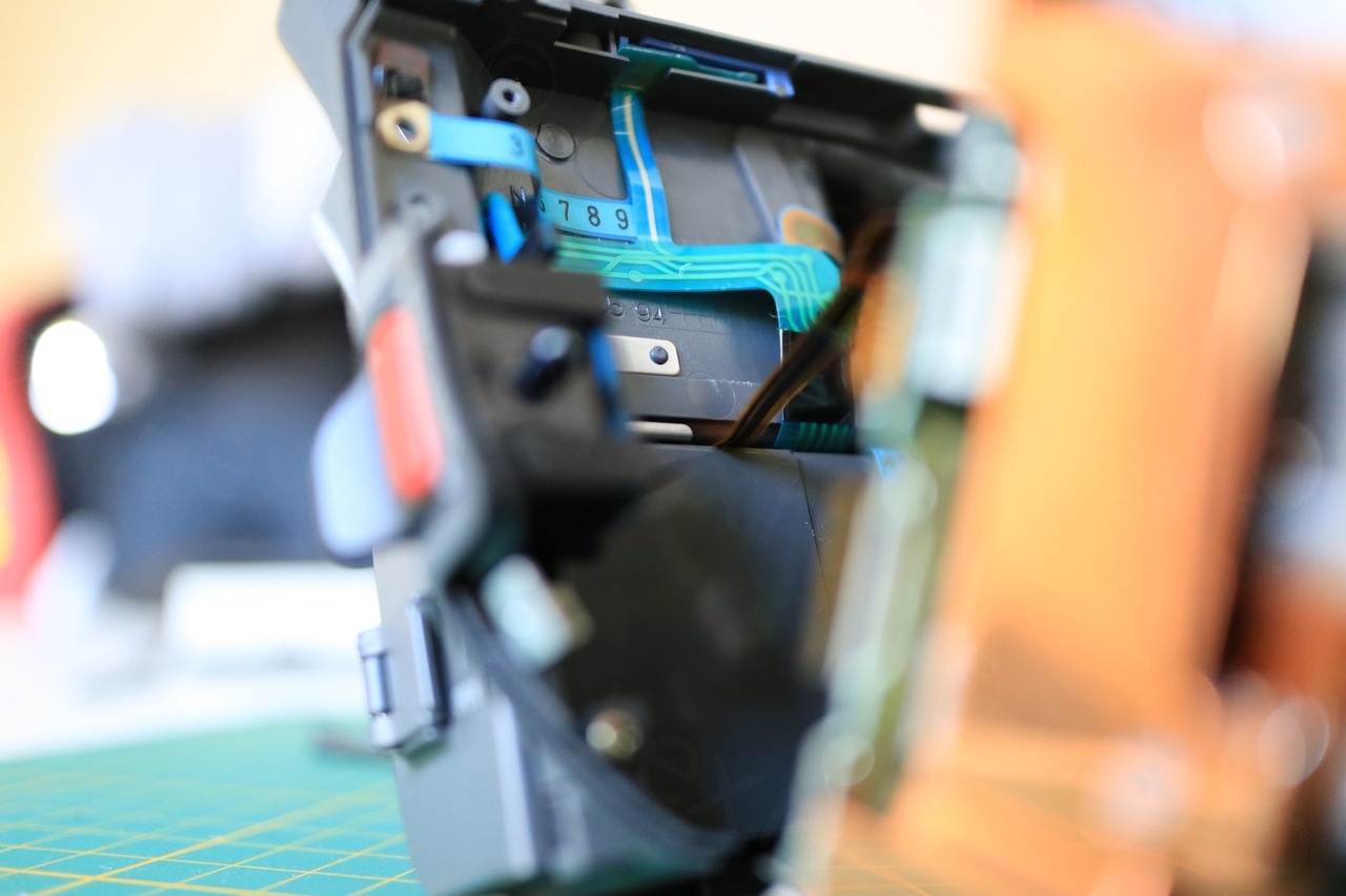
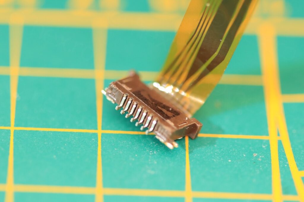
Just before testing the CRT, I need the connector (so that I don’t wire directly on the flat cable). Using the heat gun set to 300C for a bit (maybe a minute, maybe 2).
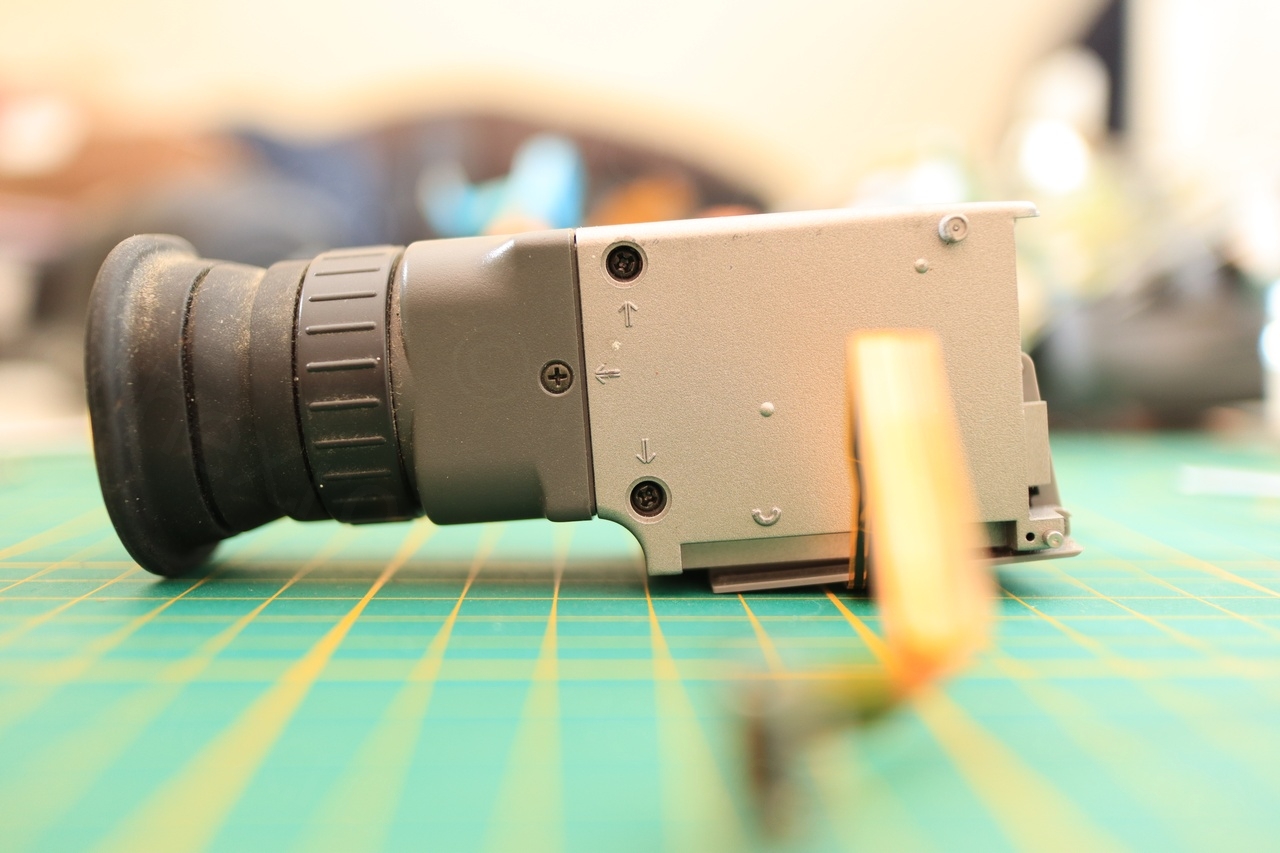
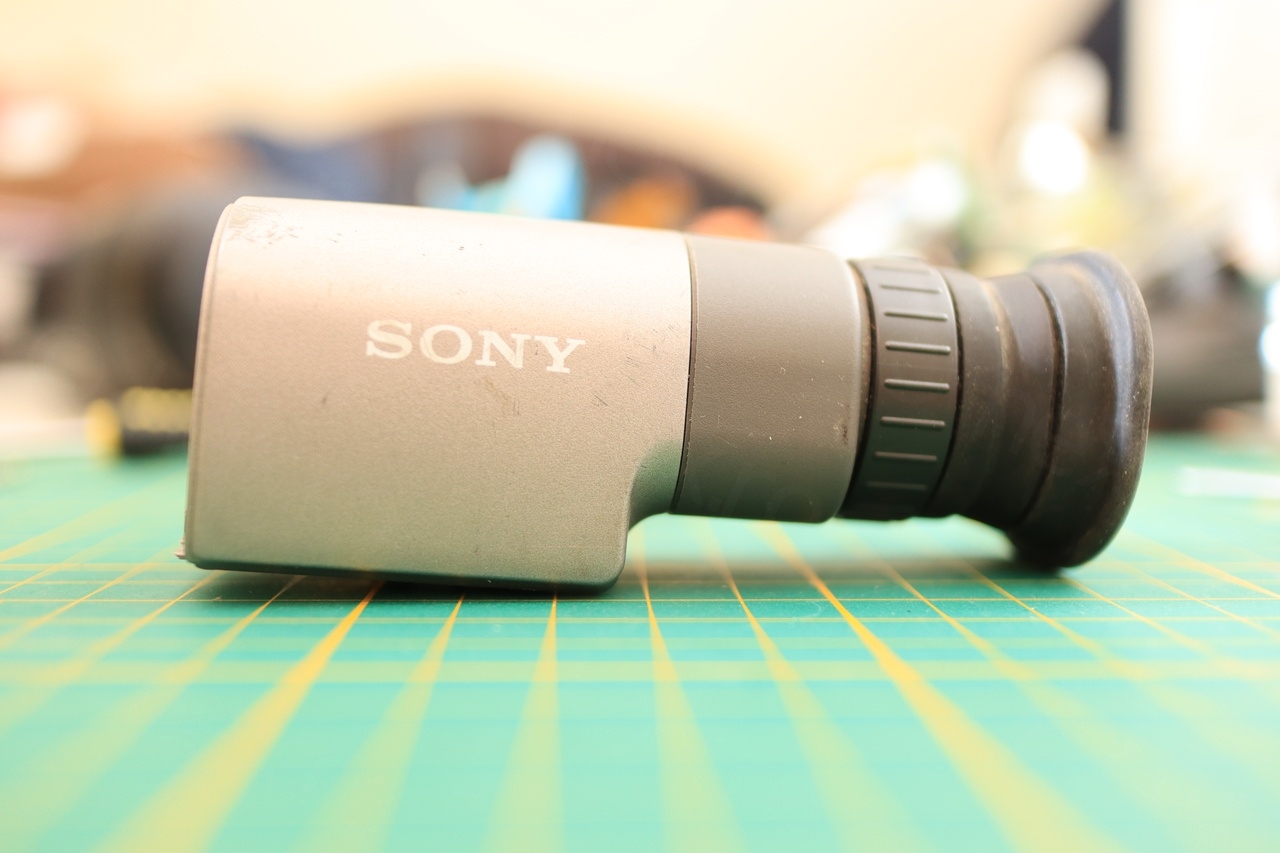
mini CRT
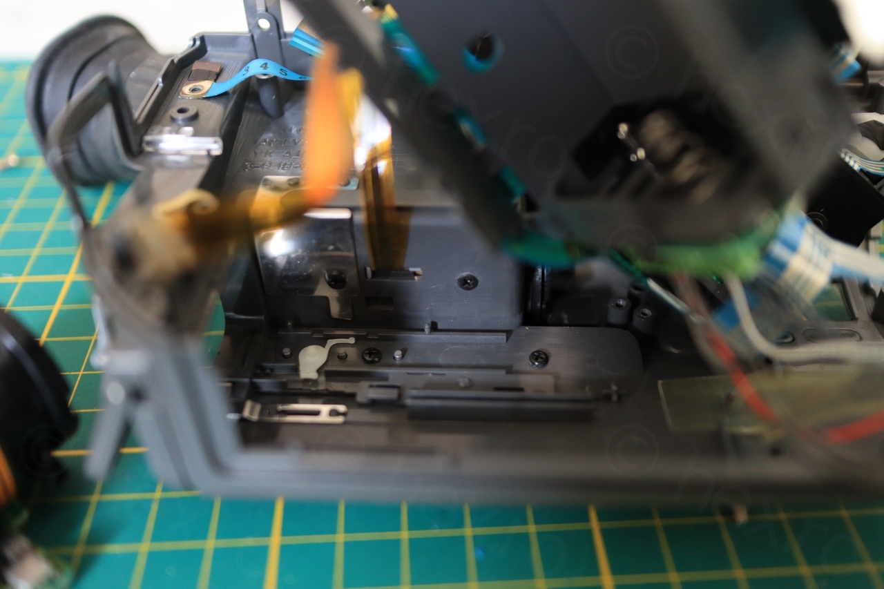
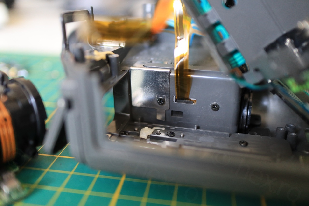
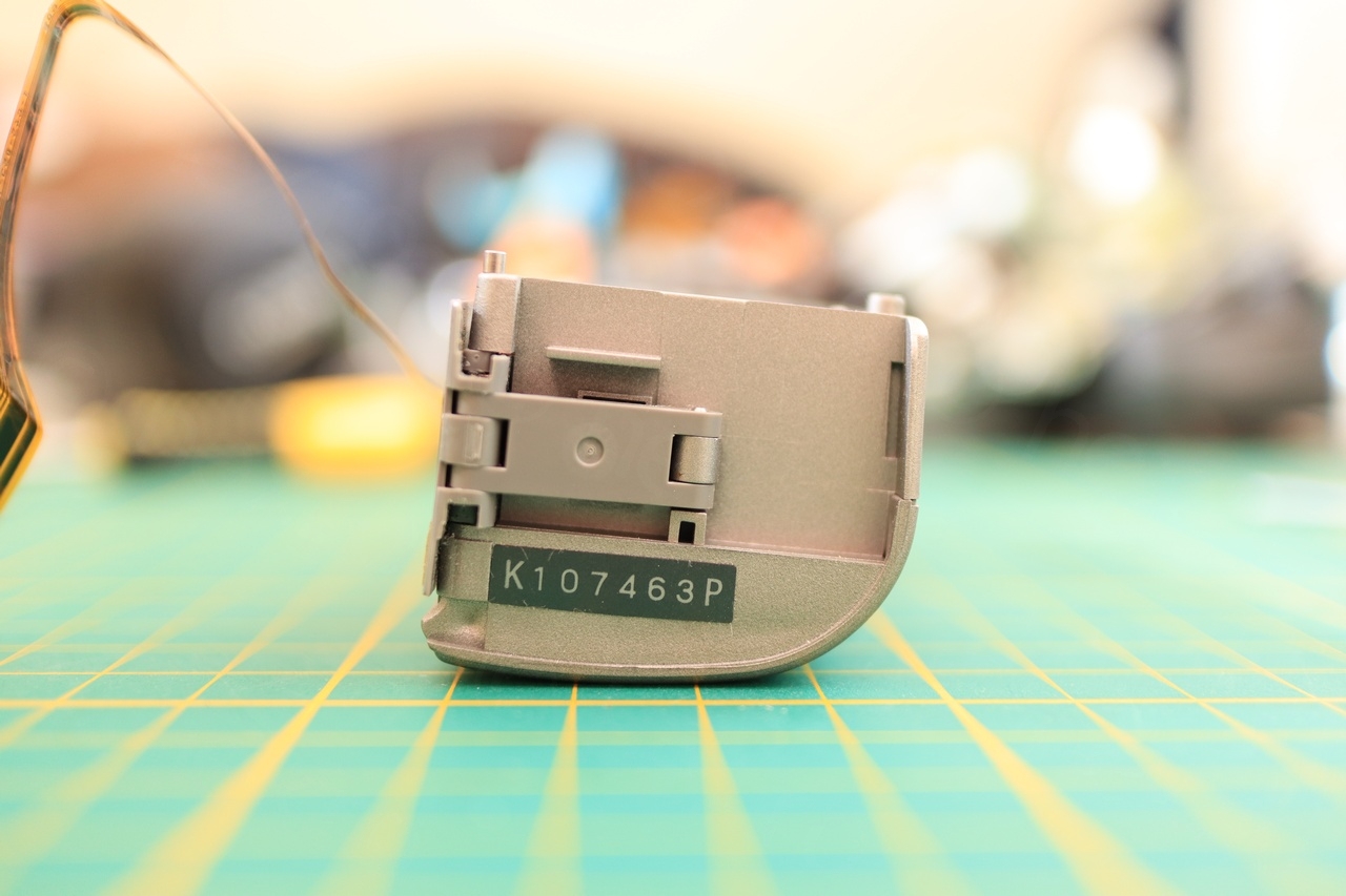
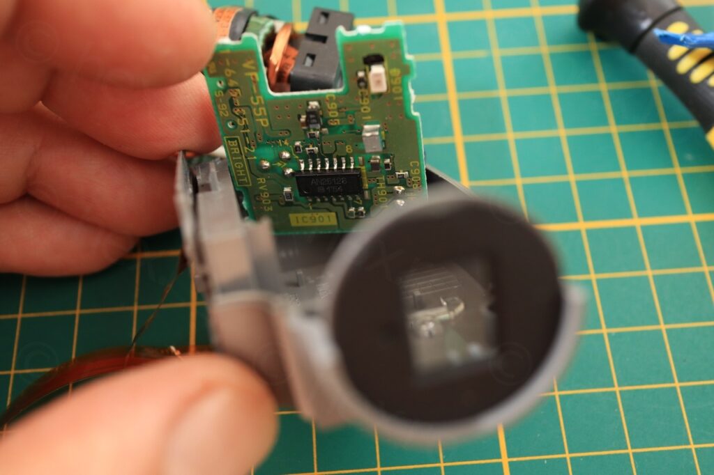
Taking a look at the EVF box:
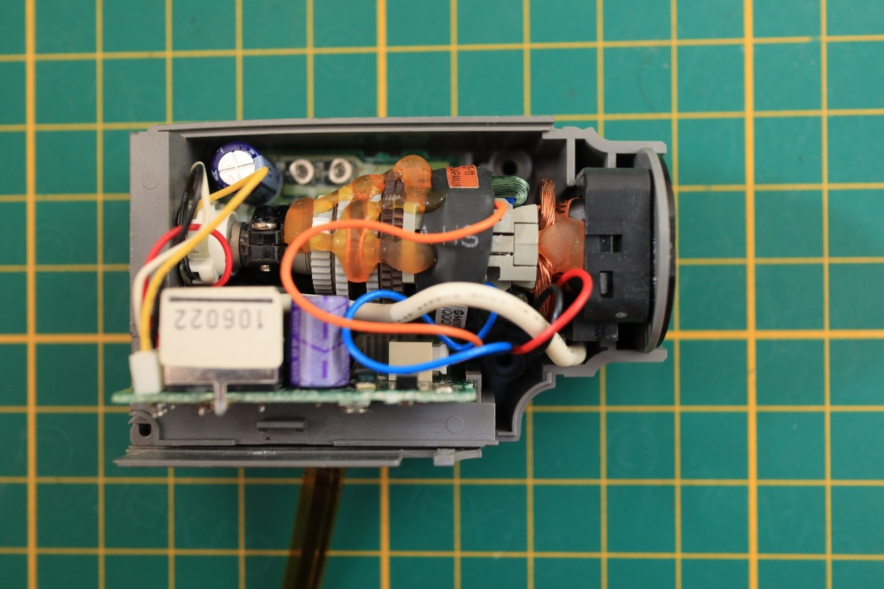
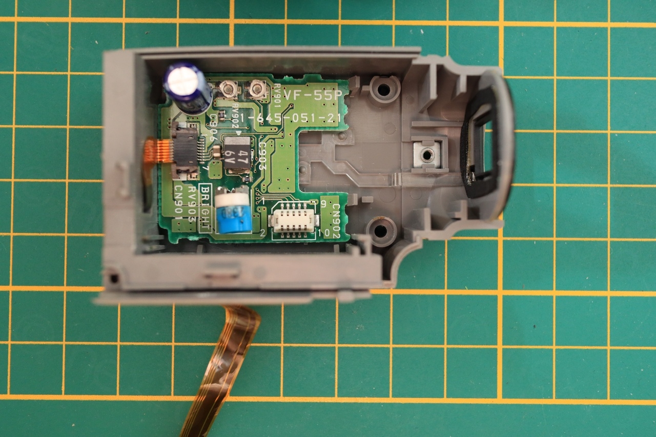
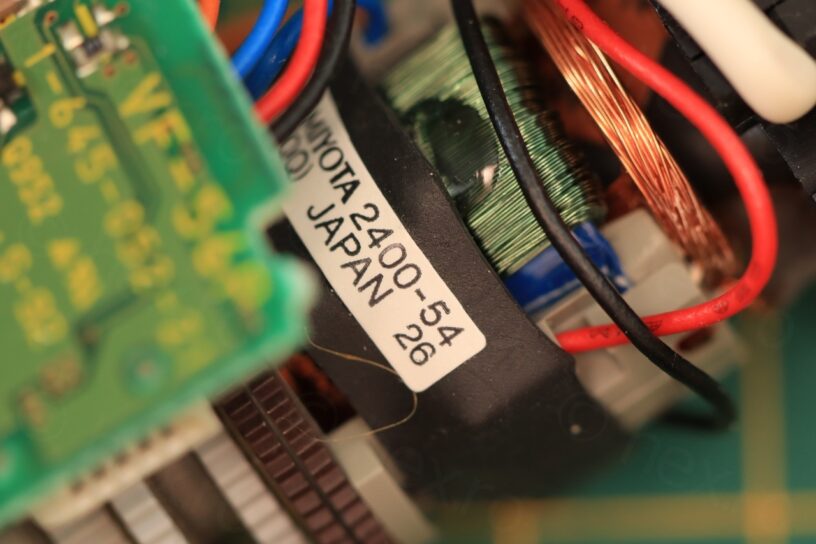
The driver board is split in half and Sony employed a connector to bridge the two parts together.
I have identified the Vcc and Gnd using the Flyback Transformer (its case is connected to GND and there are other pins directly connected to VCC), however the CRT has an issue, the image is compressed horizontally. Upon closer inspection, there does indicate a leaky capacitor around.

Connections 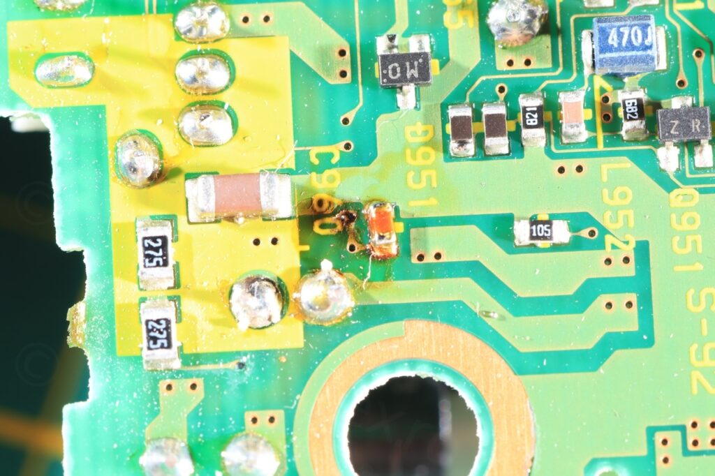
Leaky cap damage 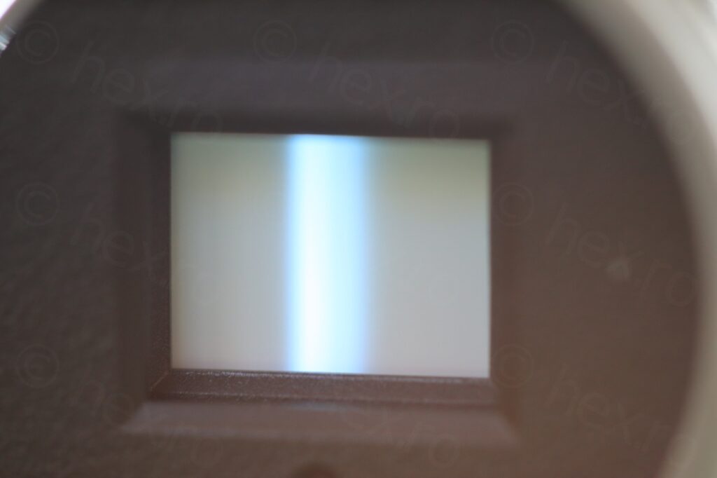
Squished horizontal
Measured the capacitor on the opposite side of the board and it turned out it has ERS > 40 ohms; cleaned the area and replaced the cap with a new one. This got the horizontal width back, but the image does not want to be stabilized:
This is supposed to show the Raspberry PI desktop. I see some vertical lines on the left also, and the image squished. The other to electrolytic capacitors tested good (both in circuit, then out of circuit) and I fiddled with the tiny pots that are on the boards, but no improvement to the ‘scroll’ speed.
While I do have other driver boards based on the same driver IC (AN2512S) and assuming the inputs and outputs of the driver IC should be similar, this would provide a direction what the problems could be.
I have also considered that maybe some of the circuitry is inside the camera itself and then the driver board does not expect a pure Video IN signal, but something that is already processed. The camera did not power on however … so I could not see if the image was at least stable vertically.
I will keep this EVF unit either for spare parts (the CRT itself) or, in case I find a working identical camera, to be able to salvage it later ..
Tehan
maybe the cap juice got in between the ic pins?
did u try washing the boards with some isopropyl alcohol?