


Table of Contents
- Introduction
- Research
- Measuring inductance from the RL circuit step response
- Measurement setup
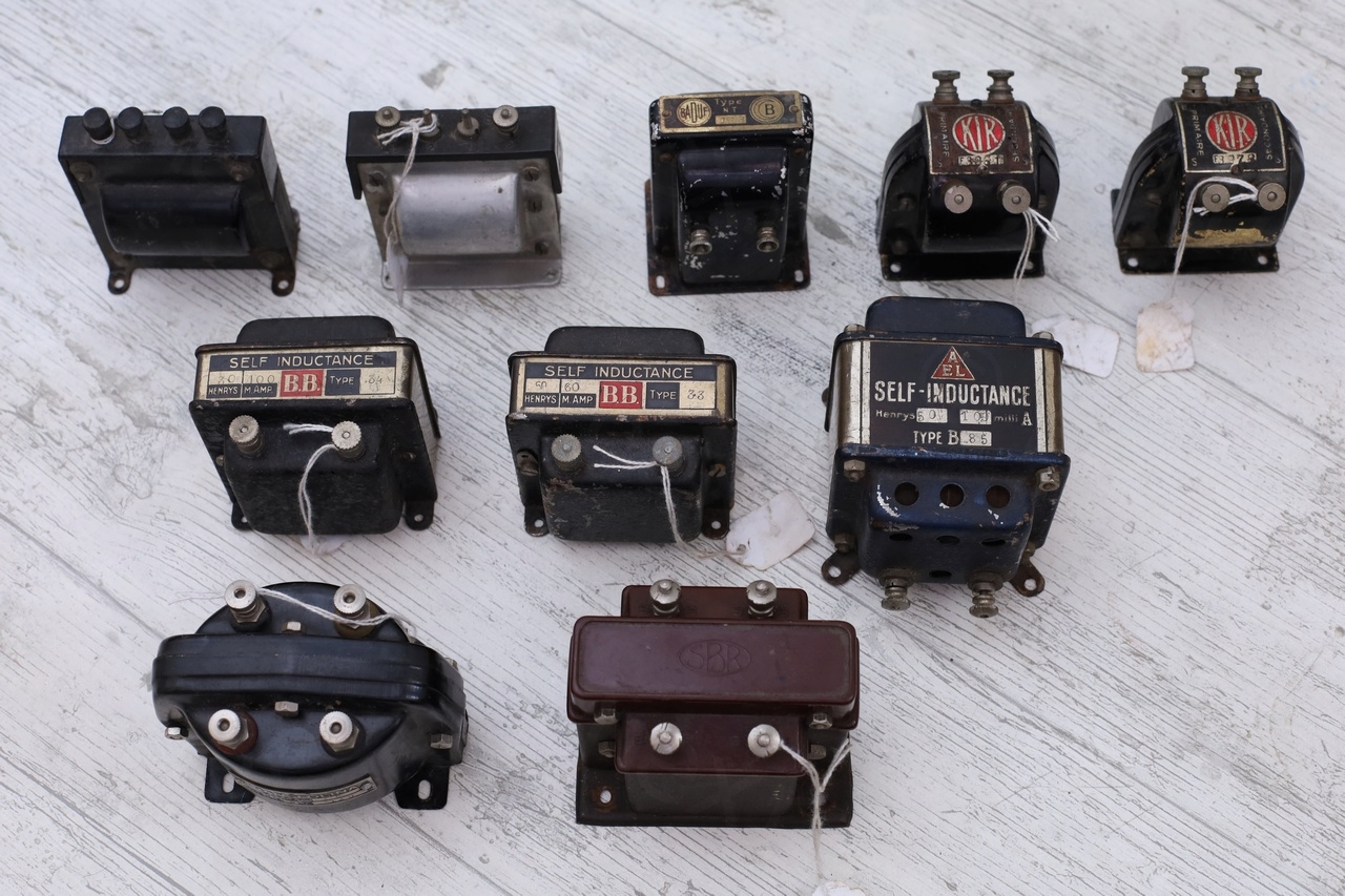
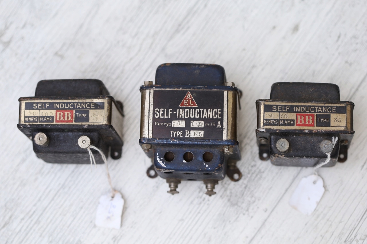
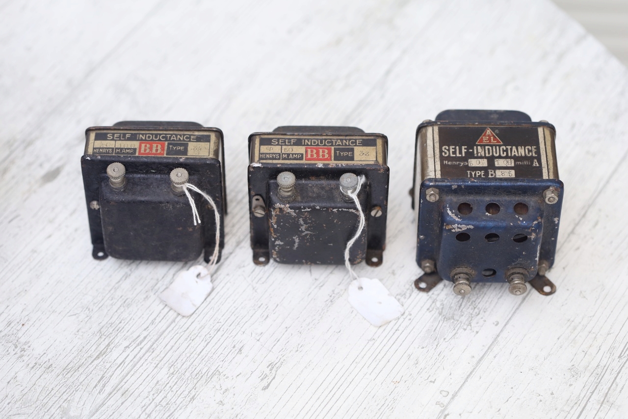
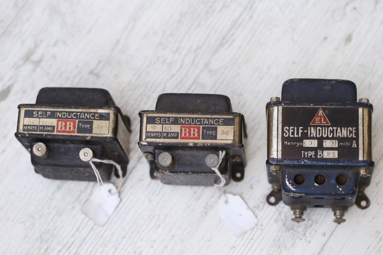
- Self-Inductance model B.B. Type 34: 30H, 100mA
- Self-Inductance model B.B. Type 33: 50H, 60mA
- Self-Inductance model AEL Type 85: 50H, 100mA
- Conclusion
Introduction
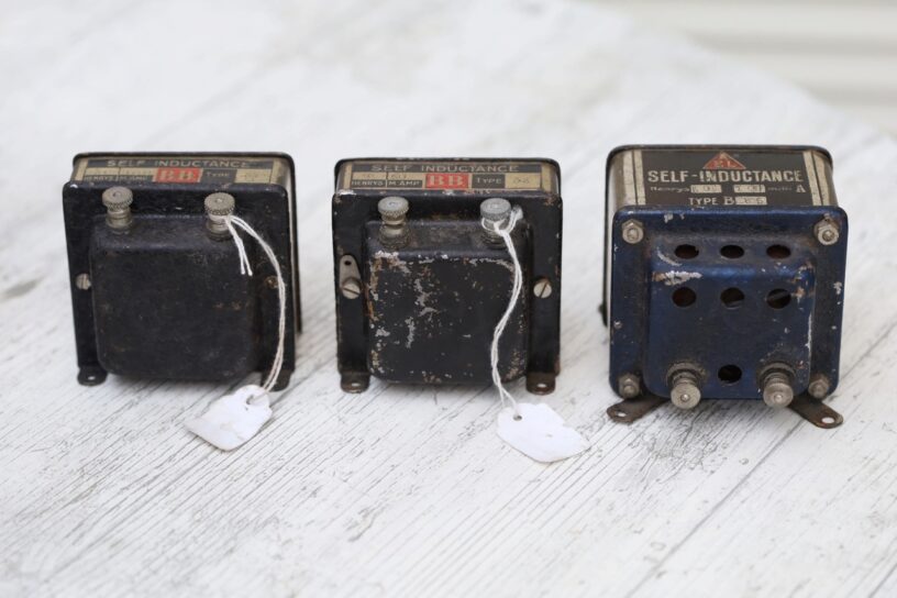
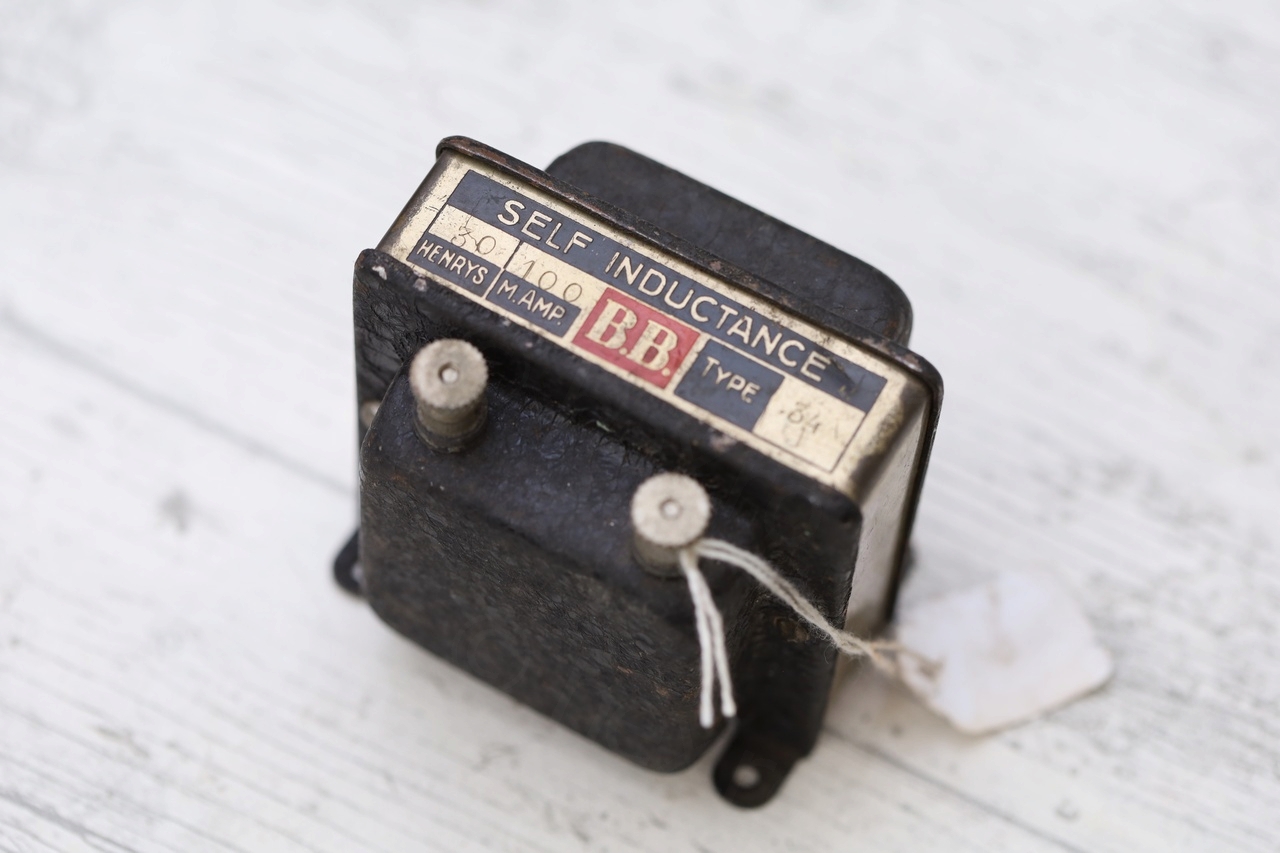
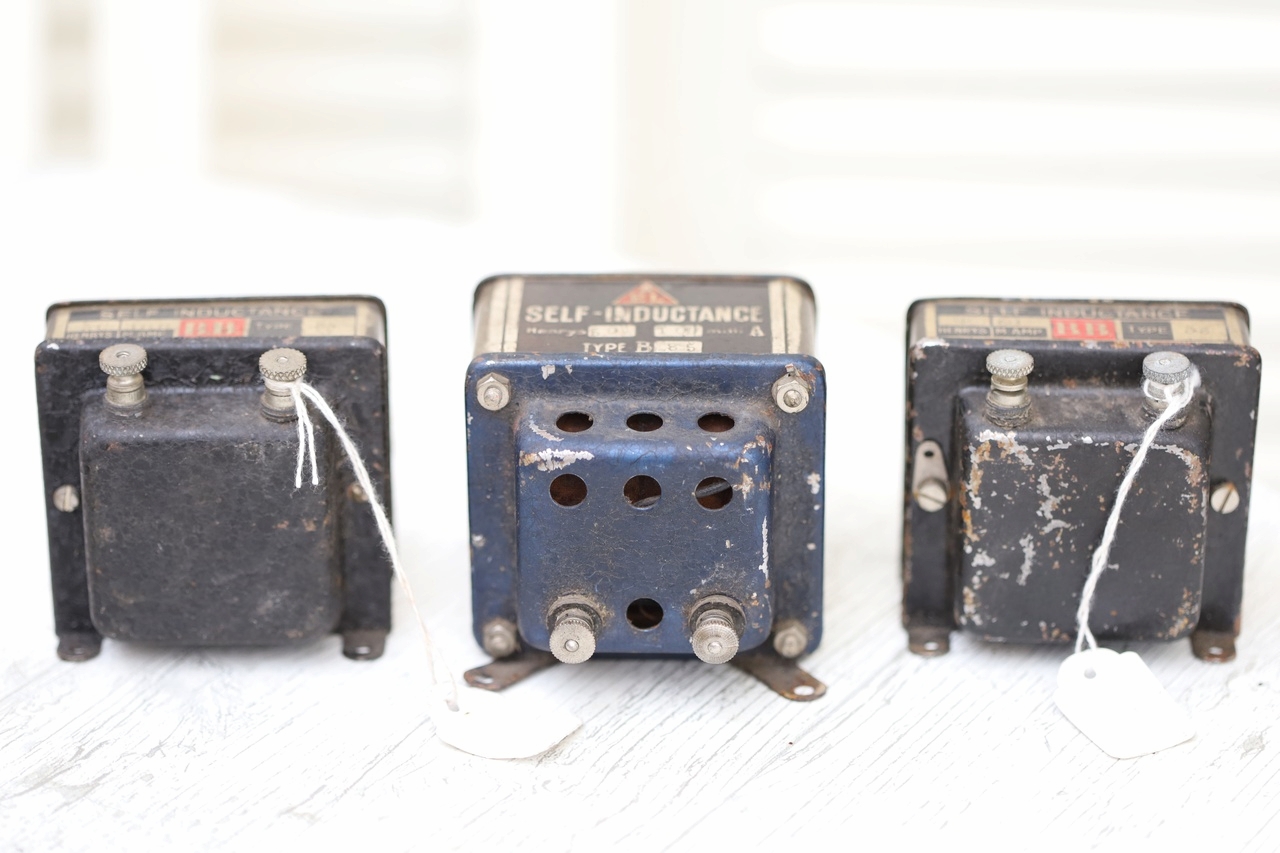
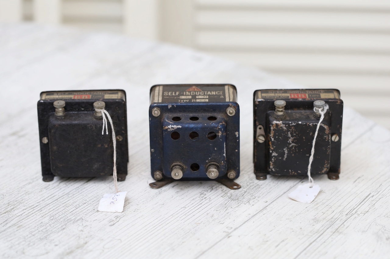
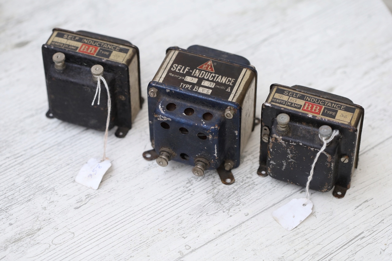
The local flea market at Jeu de Balle is special… many times boring, but sometimes rare / interesting objects pop up. On one of these occasions I found a bunch transformers and inductors which I have never seen before.
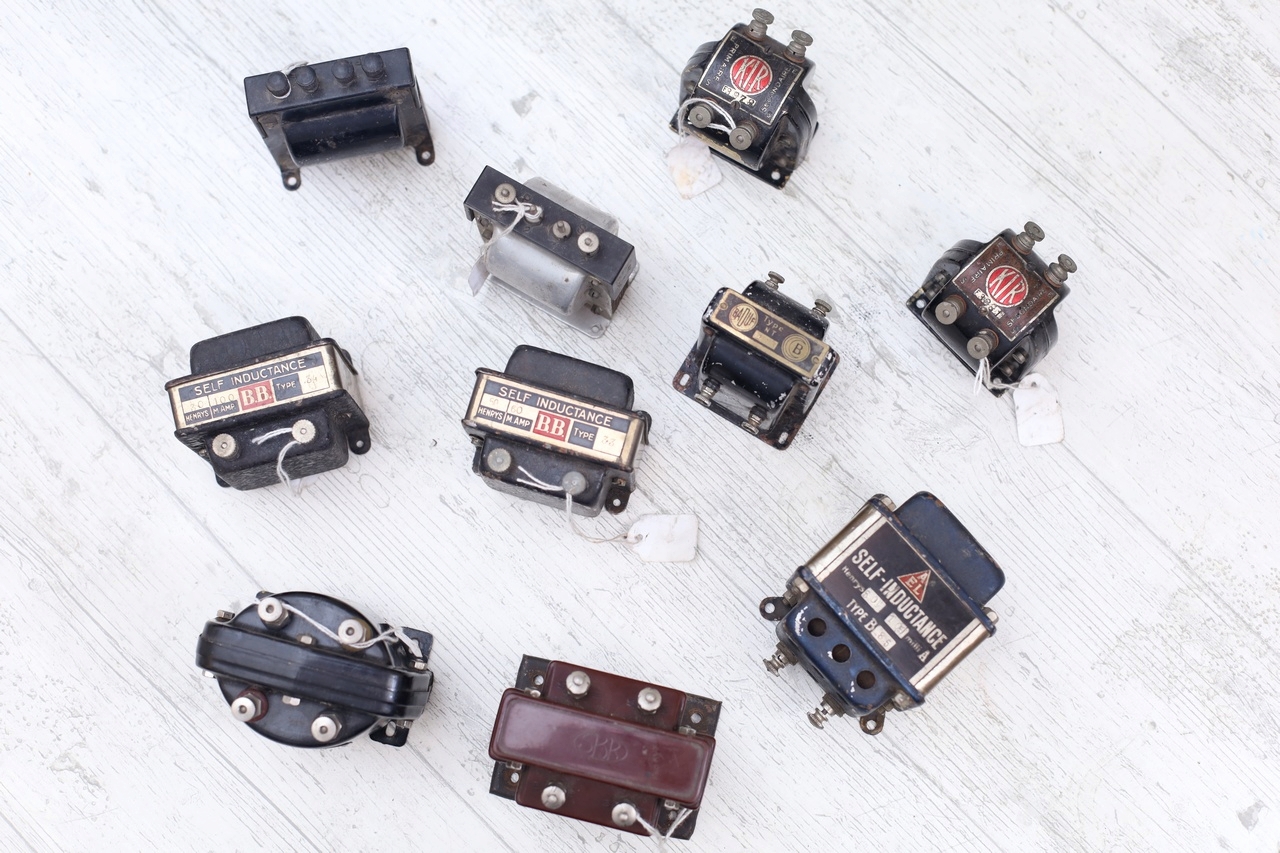

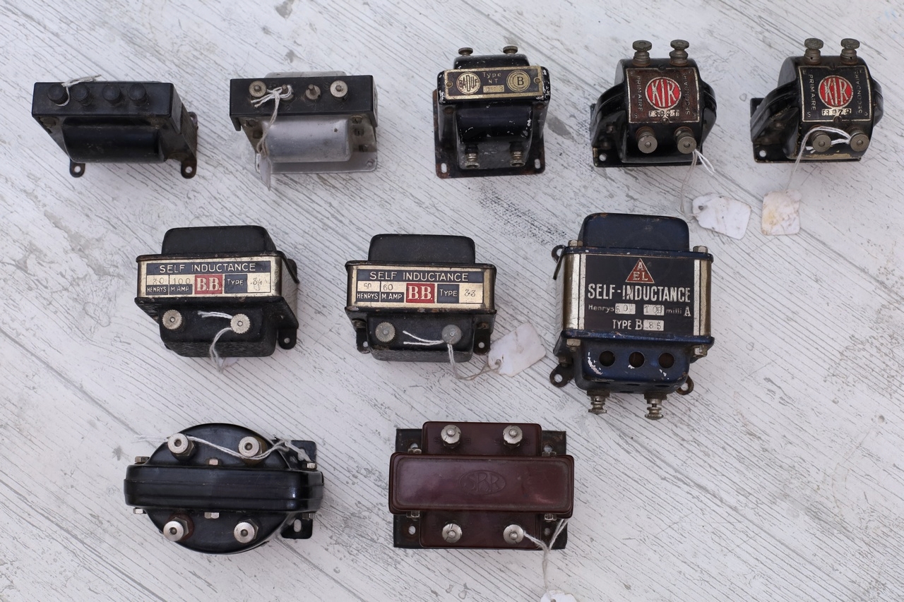
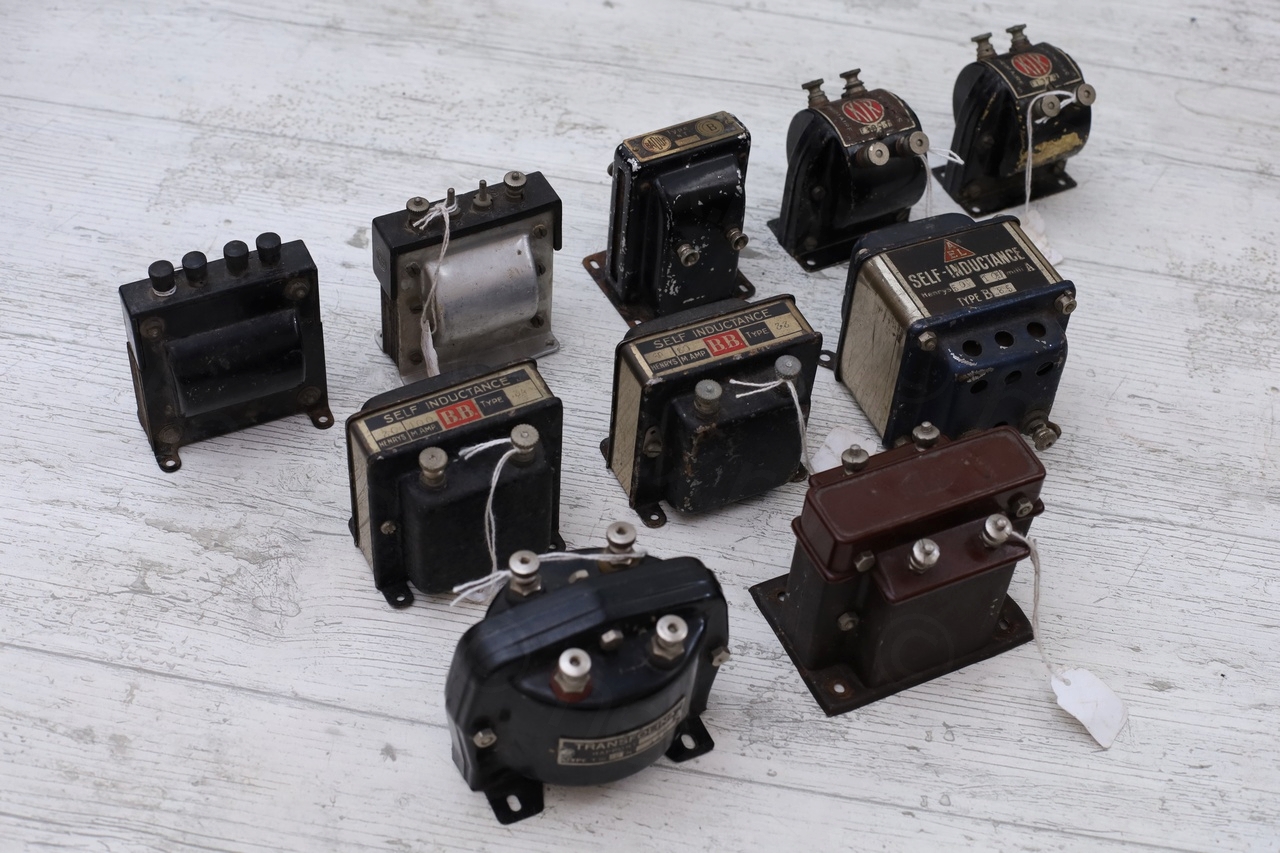
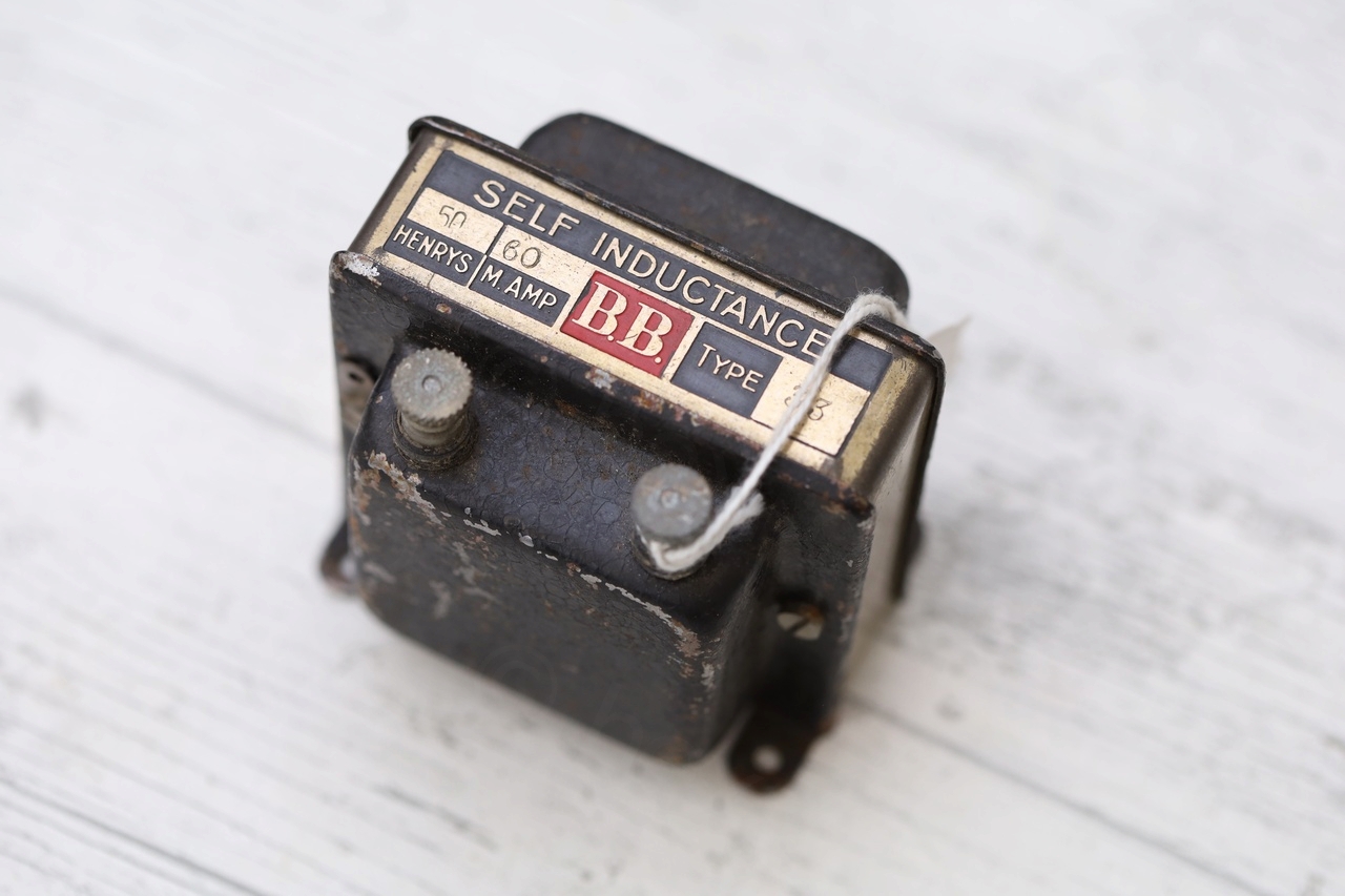
I am used to see transformers having screw terminals or just wires coming out of them, but thumb screws ? With metal plates for model number ? They really looked from another era!
The problem started when I wanted to measure the inductors … as my LCR meter seem to struggle, reporting weird values.
Research
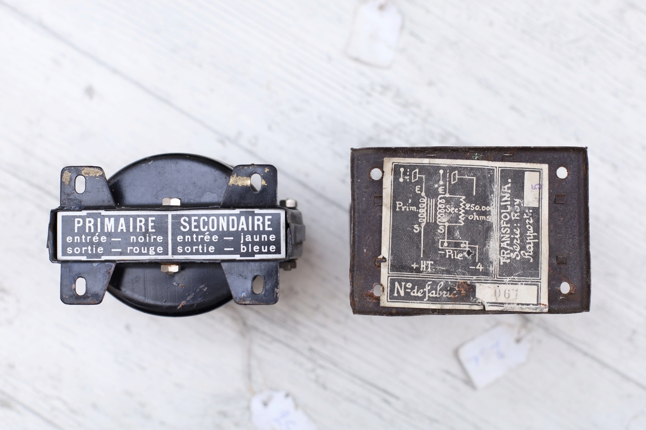
One of the inductors was branded AEL which and this soon led me to the https://www.radiocollection.be/fr/AEL_01_fr.html website. Amazing source of information! I could not believe finding the exact information about the model I was looking for, the B85:
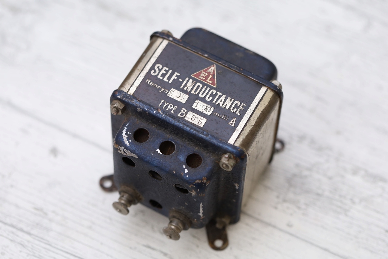
Most of the details were already stamped on the inductor itself, but there were two crucial ones: it is a DC filtering inductor and that it has an iron core. Ahaaaa!
These inductors were never made to be used with AC but LCR meters measure inductance using an AC test signal.
Measuring inductance from the RL circuit step response
I was curious to determine L but not using any AC / frequency measurements. The theoretical details are on Wikipedia’s RL Circuit page. It boils down on measuring the time constant (τ) from an RL circuit step response and then calculating L = τ * R.
For a L = 50H and using an resistor of 10kΩ , the τ = L / R = 0.005s = 5ms, which is easily measured with an oscilloscope.
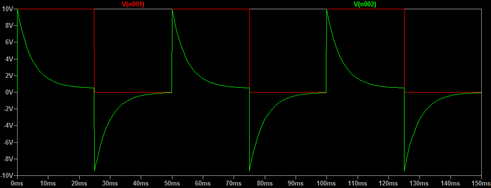
I made a small LTSpice simulation to see what I would expect on the oscilloscope:
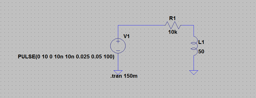
In RED is the stimulus between 0V and 10V (this is the maximum that my signal generator can put out). GREEN is expected voltage of the inductor:
Measurement setup
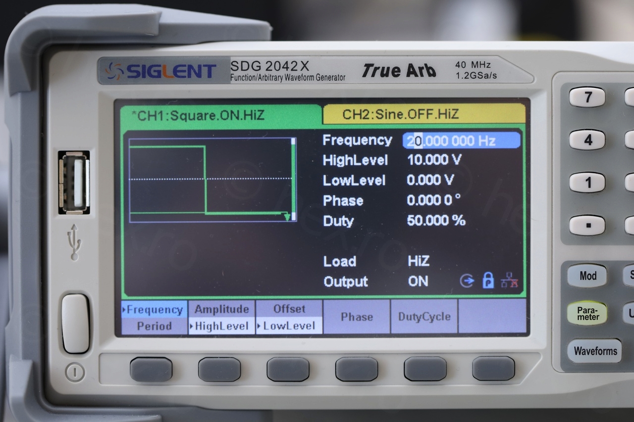
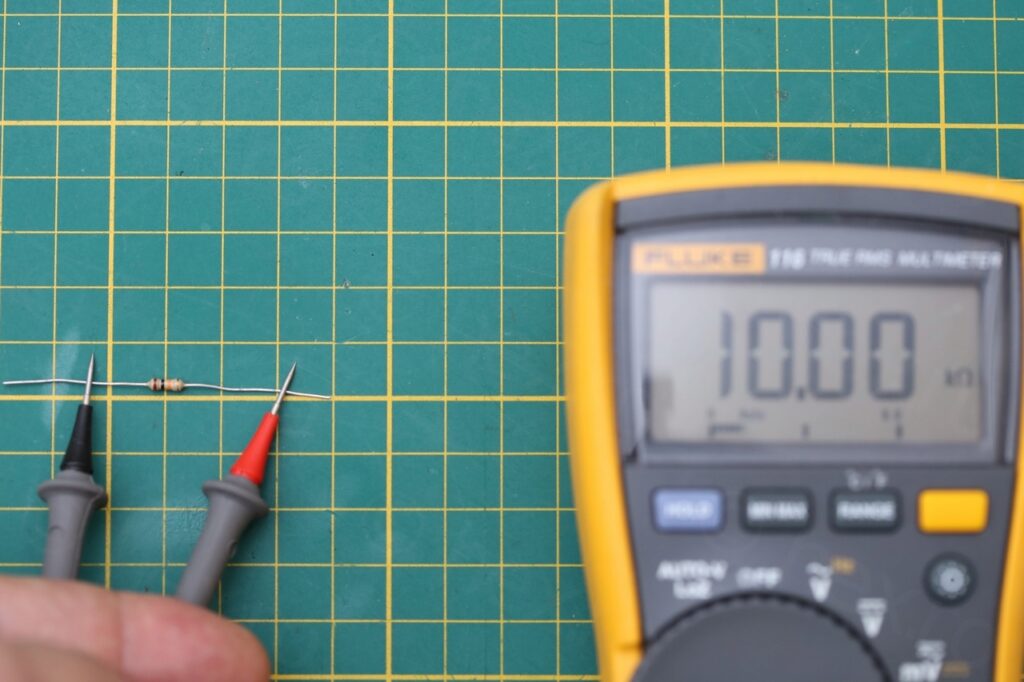
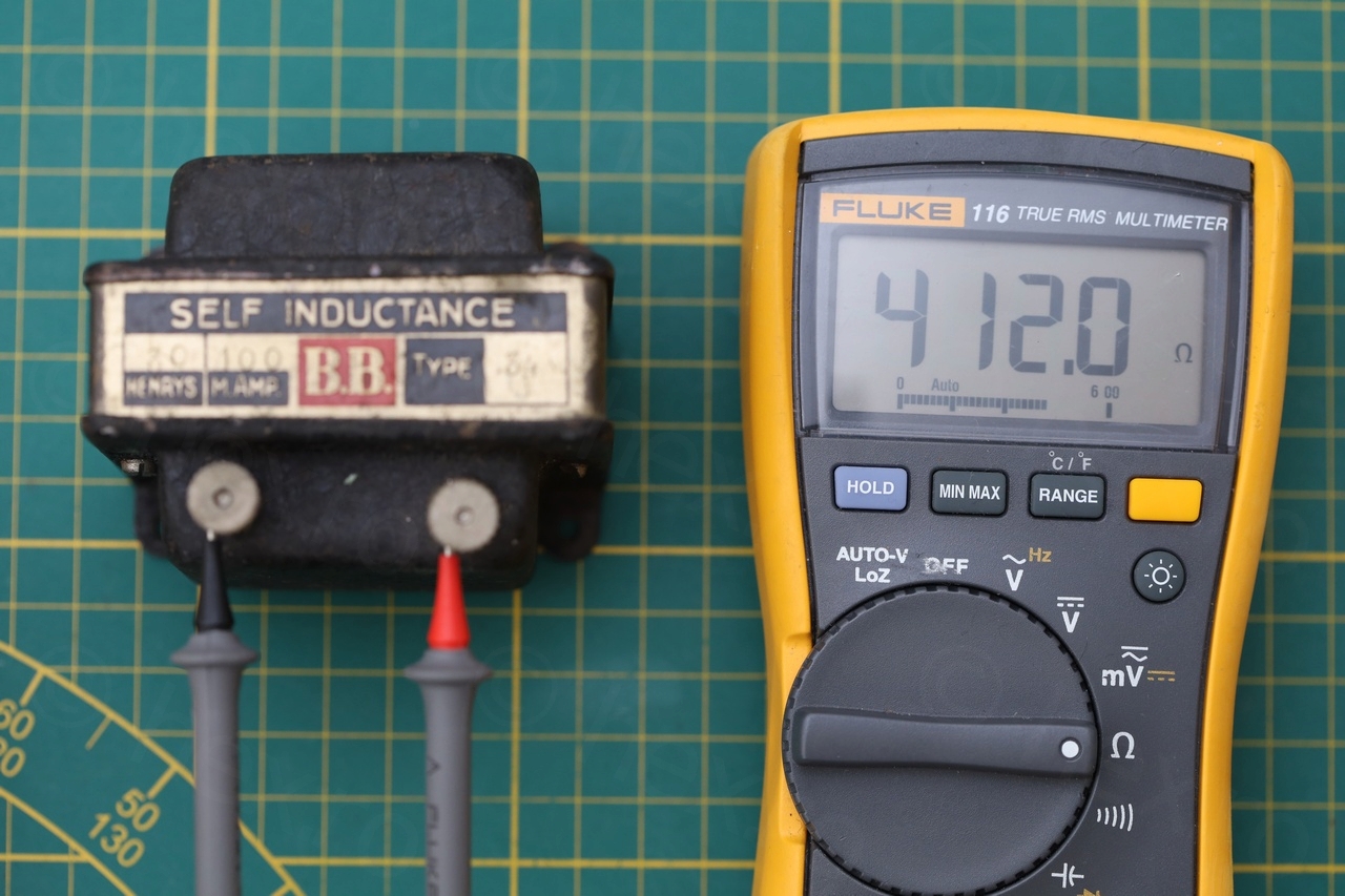
The instruments used were Siglent SDG 2042X (Arbitrary Waveform Generator, to put out a 20Hz STEP signal) and a Siglent SDS 1104-E oscilloscope to measure the voltage across the inductor. Fluke 116 multi-meter was used to measure the DC resistance of the inductors and to conform that the chosen resistor is 10kΩ.
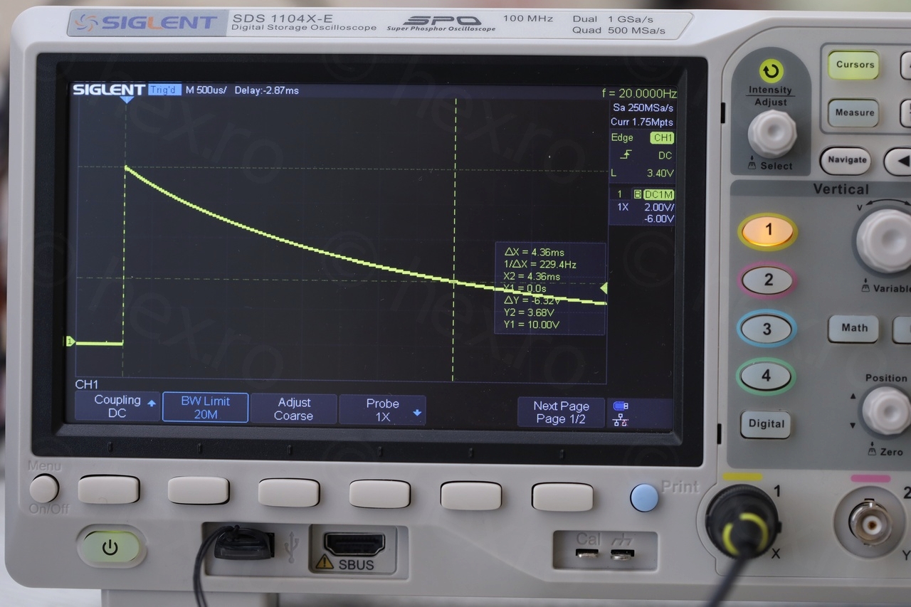
To help positioning the cursors more accurately, oscilloscope needed some setup. To get thinner trace : averaging (16 samples), display changed to Dots (instead of Vectors), Bandwidth limited to 20MHz and Memory Depth limited to 14k. Trigger was setup on Edge and 3V. Using Horizontal / Vertical positioning, the trace was moved to the lower left – a way of zooming into the signal. I have activated also XY cursors (all 4).
According to the theory, τ is the time where the inductor voltage reaches 36.78% from the initial voltage. So the Y cursors have to be positioned at 10V and 3.68V respectively, and X (time) cursors, one set at t = 0 and the second one set to intercept the Y2 cursor and the trace. The X2 – X1 will be τ.
I mentioned the LCR meters:
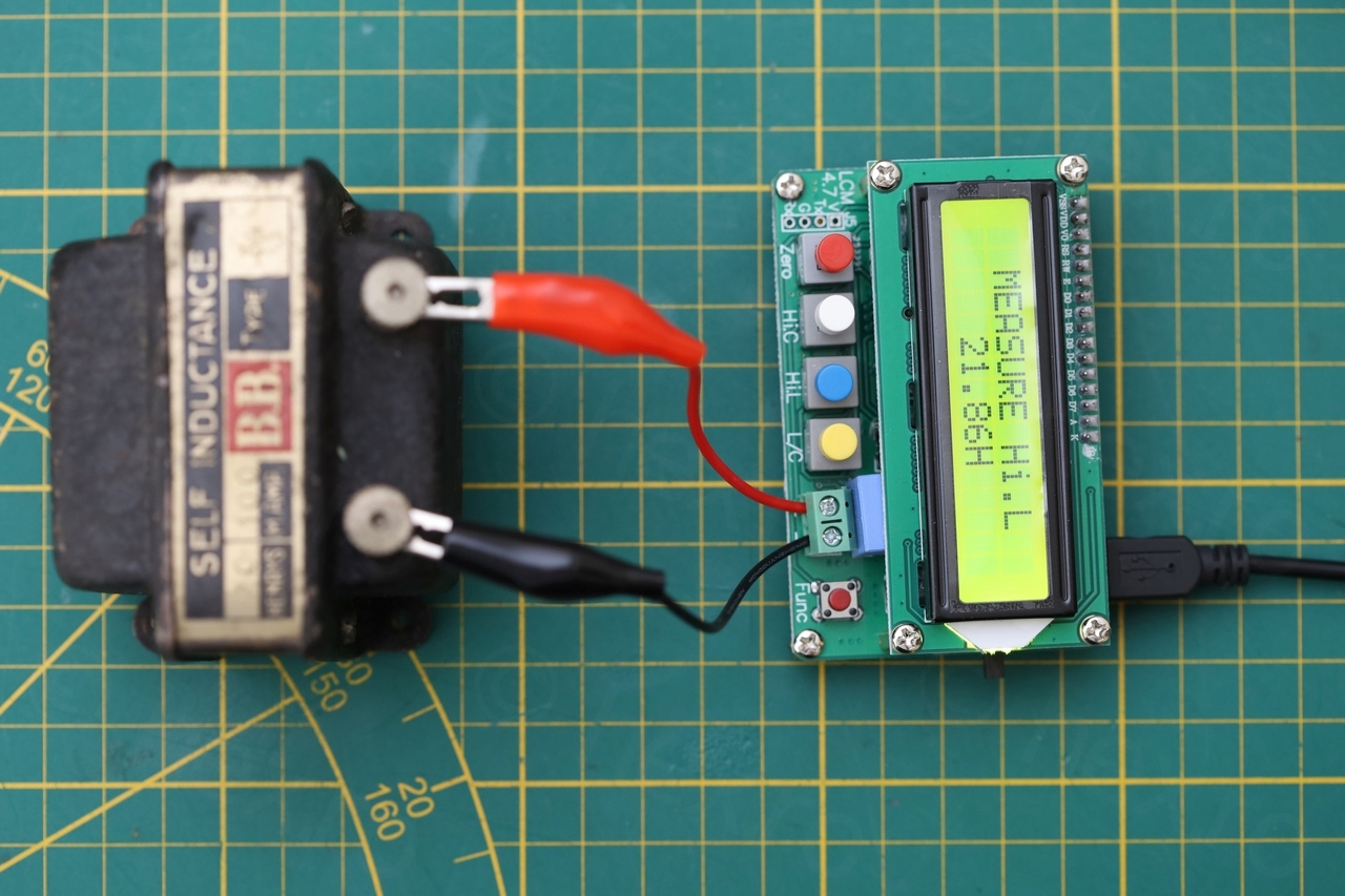
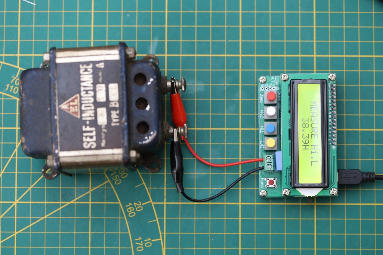
- LC100-A LCR Meter (rated to 100H)
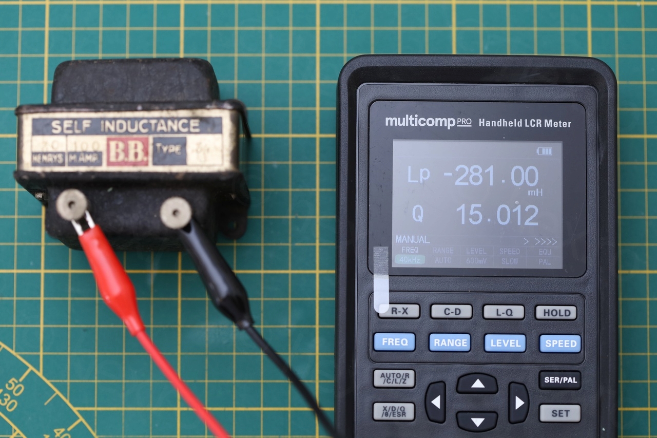
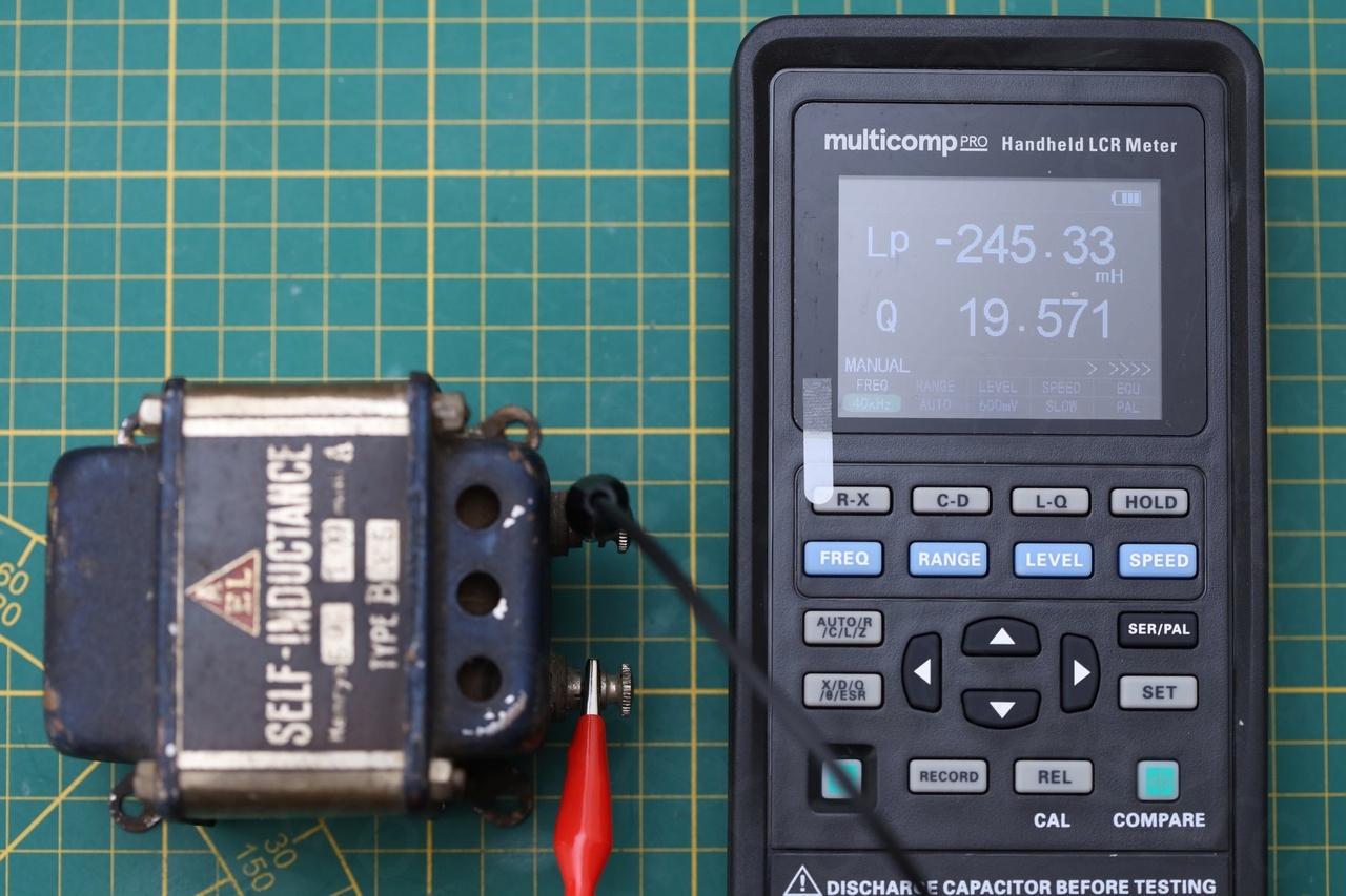
- Multicomp PRO MP700434 – Handheld LCR Meter (rated for 2000H)
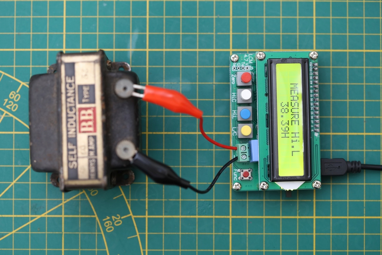
The LC100-A meter was used in Hi.L mode.
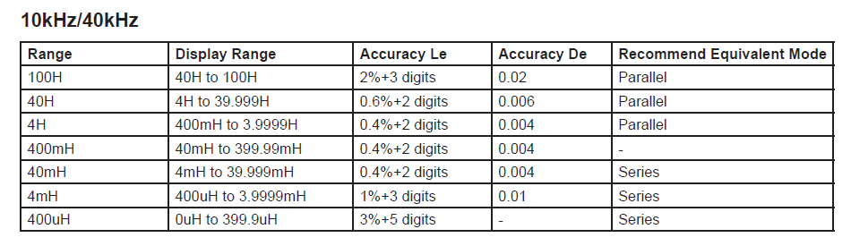
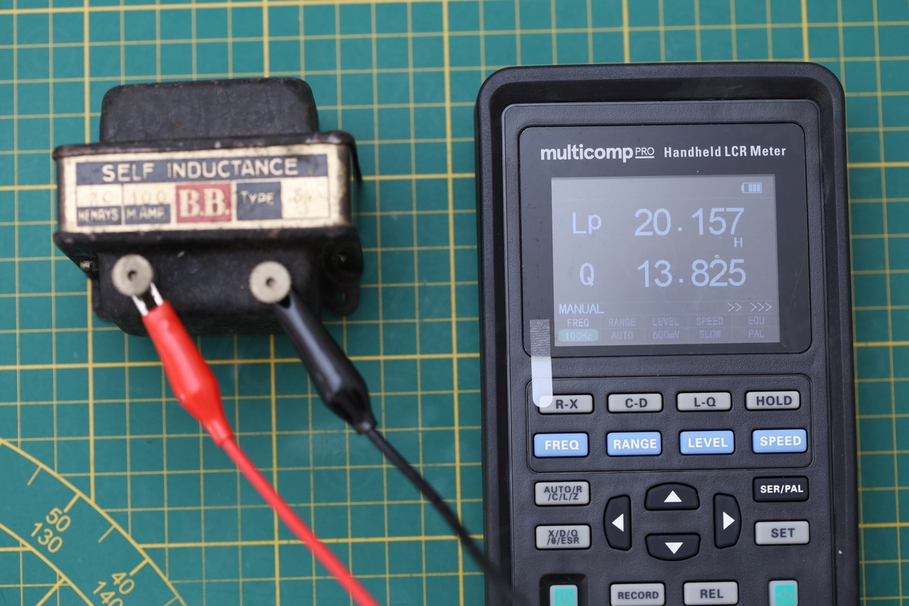
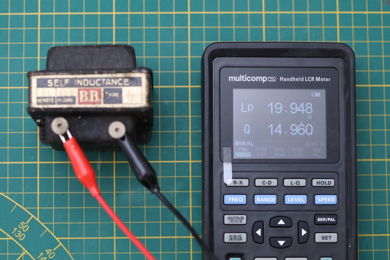
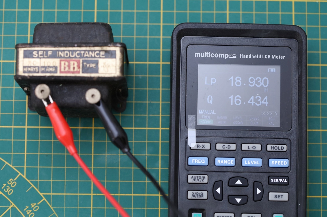
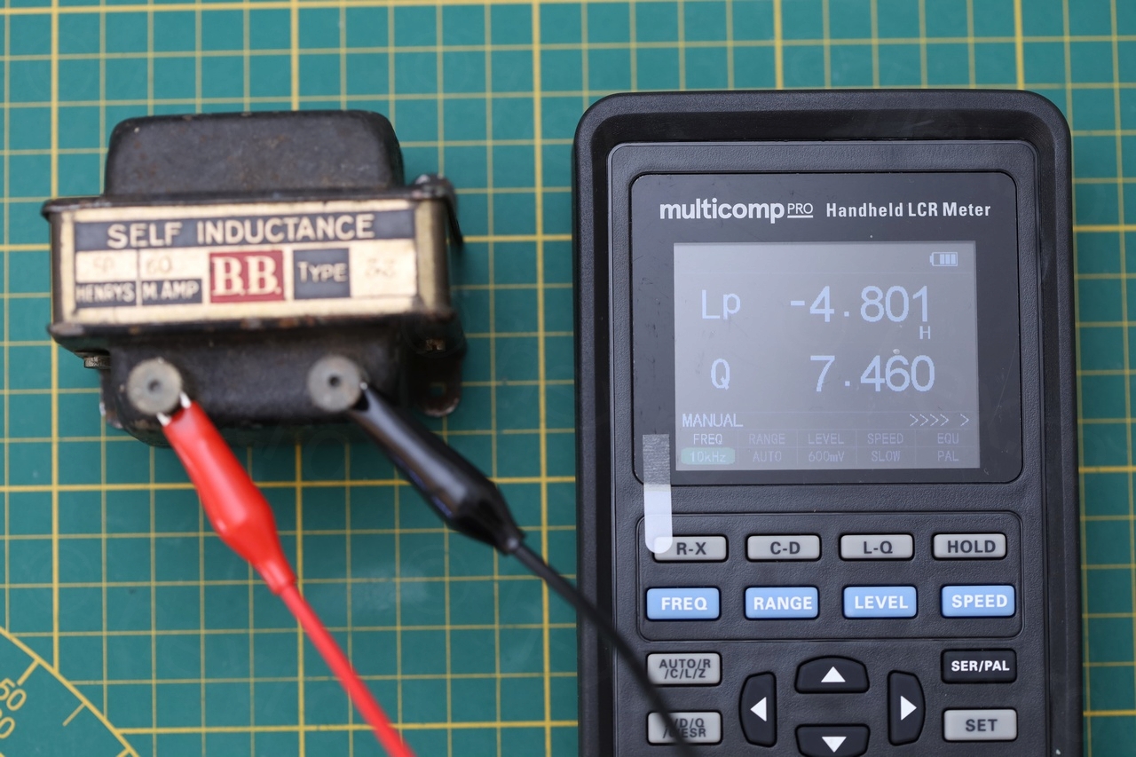
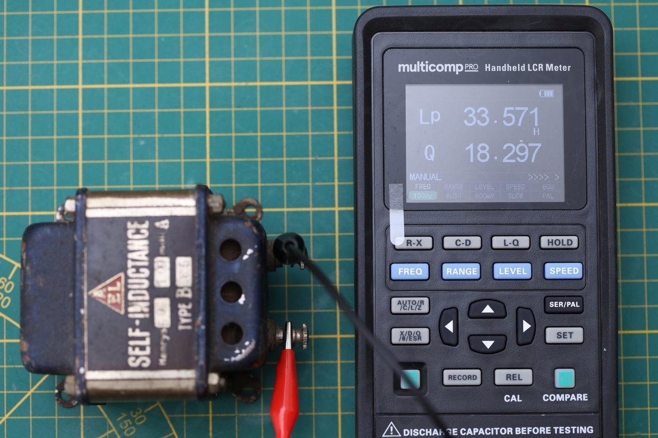
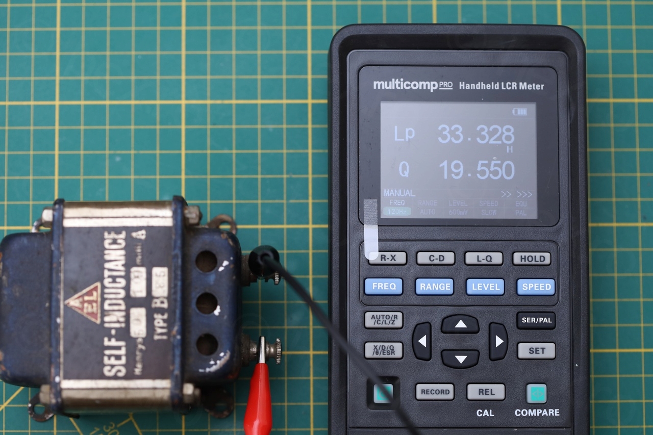
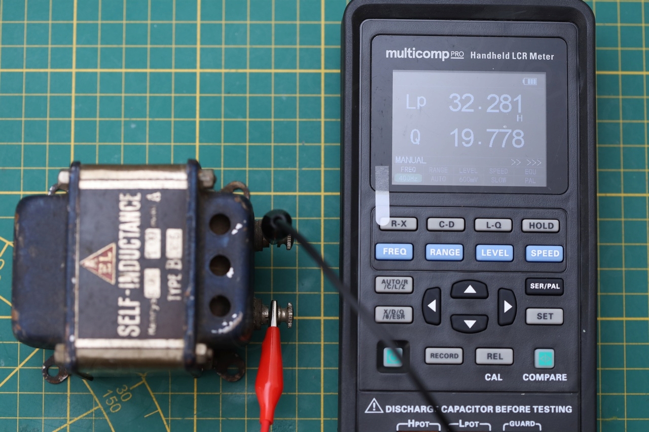
Multicomp Pro manual does mention that the 30-50H inductors have to be measured in Parallel mode – but only some test frequencies cover the 30-50H range: 100Hz/120Hz/400Hz (with better accuracy) or 10kHz/40kHz frequencies for less accuracy. The other test frequencies: 1kHz/4kHz, or >40kHz do not cover the range of 30-50H.
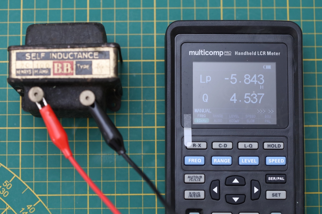
It was the Multicomp Pro LCR meter that measured weird values these inductors in the 10kHz/40kHz range : inductance was reported as negative, although the manual states the ranges:
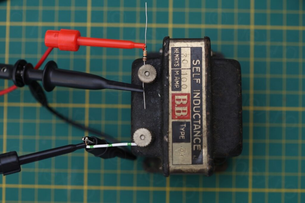
Self-Inductance model B.B. Type 34: 30H, 100mA
The first inductor I measured:
Its step response though:
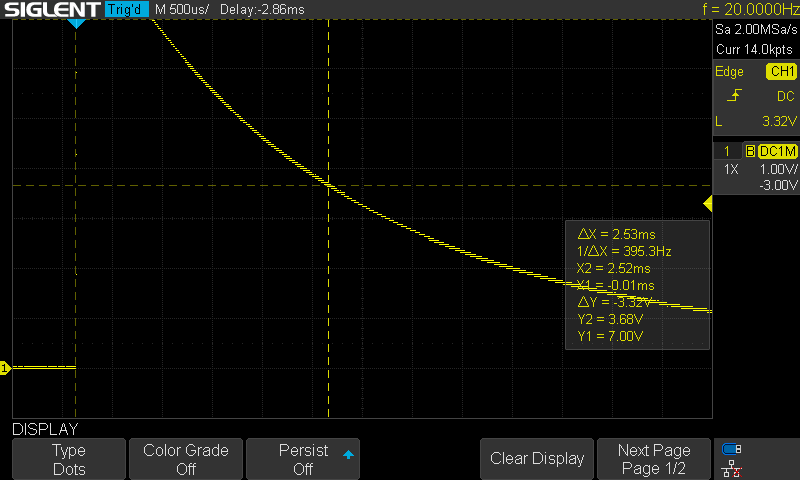
Since τ = 2.53ms and the total resistance is 10412Ω (R = 10kΩ + 412Ω DC resistance of the inductor) it follows that its inductance L = 0.00253 * 10412 = 26.3H which is closer to the stated 30H of the inductor (vs 20H / 21H reported by the meters).
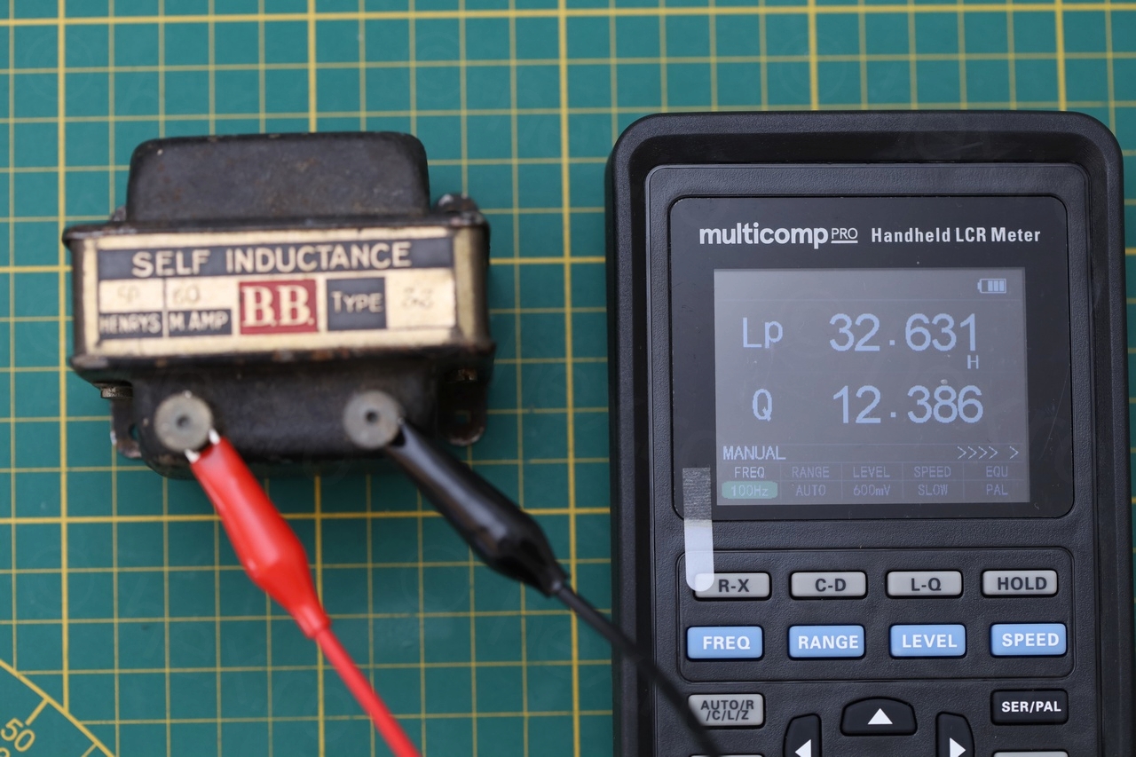
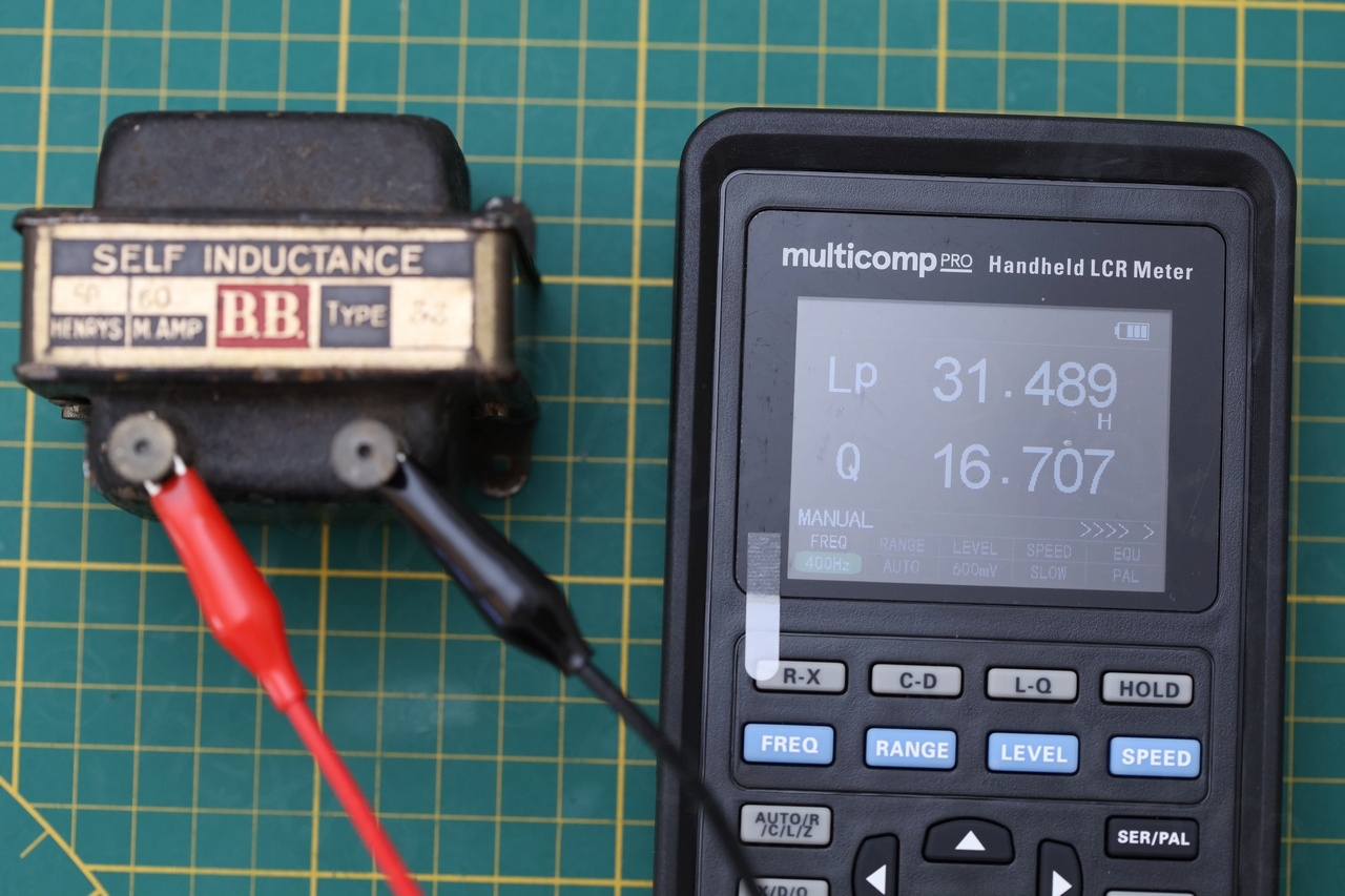
Self-Inductance model B.B. Type 33: 50H, 60mA
Measurements:


Its step response was:

It follows then that L = 0.00469 * (10000Ω + 955Ω) = 51.38H
This looks to me a lot more accurate that what the meters were reporting (~32H).
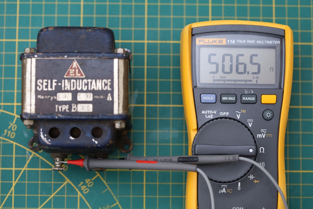
Self-Inductance model AEL Type 85: 50H, 100mA
Measurements:


Its step response was:
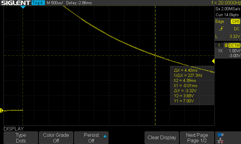
It follows then that L = 0.00440 * (10000Ω + 506Ω) = 46.23H
Conclusion
I found that for large inductors with iron core meant for DC current filtering, it is more useful to use an Oscilloscope to infer their inductance.
Leave a Reply