

Introduction
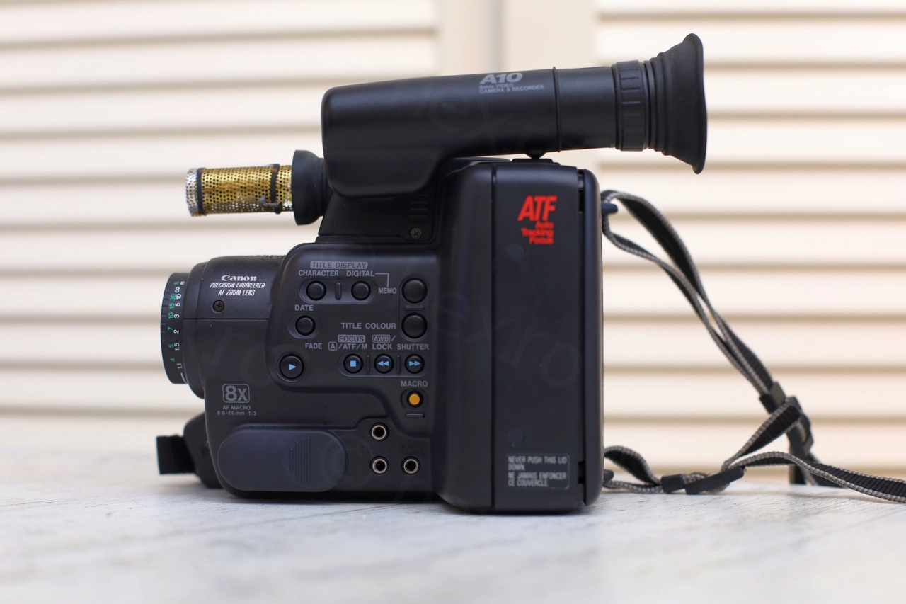
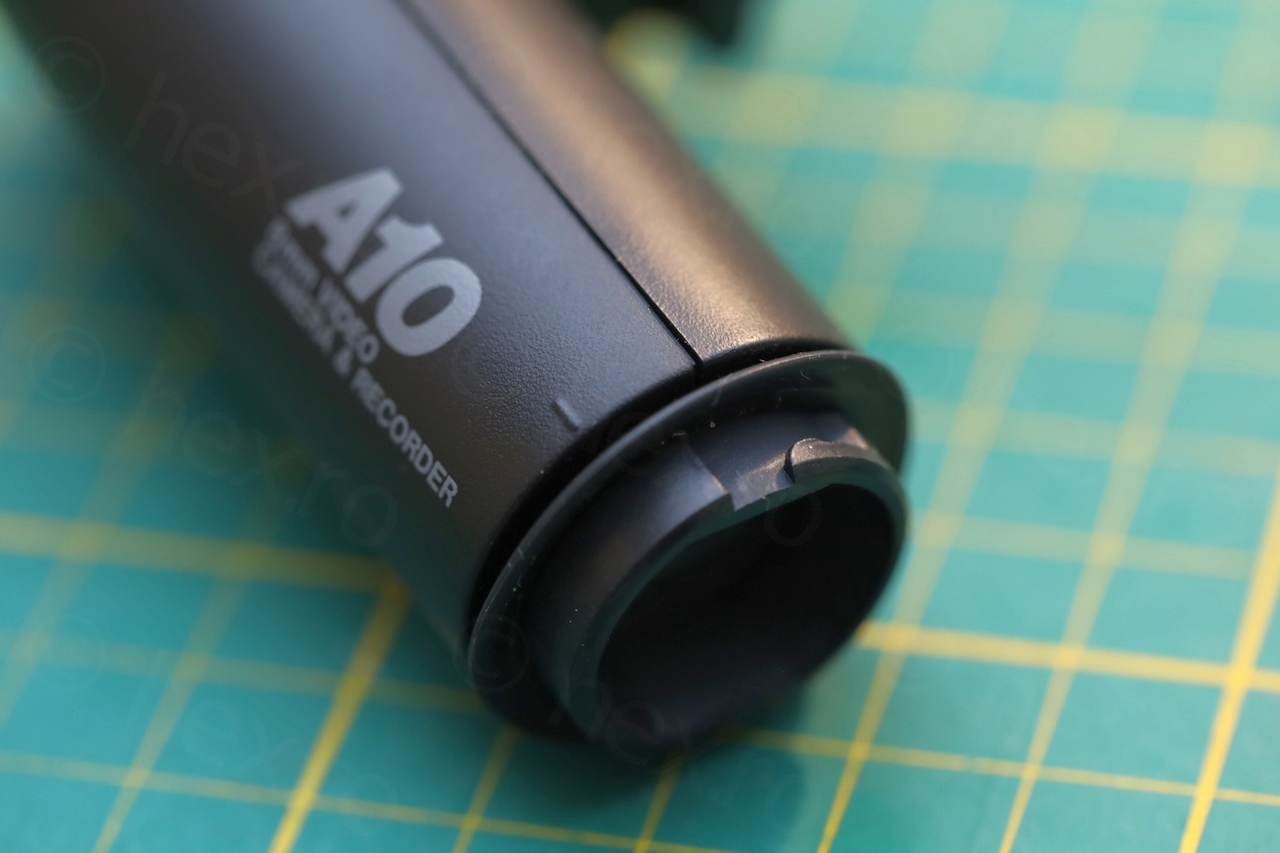
I found this mini CRT inside a Canon A10E Video Camera.
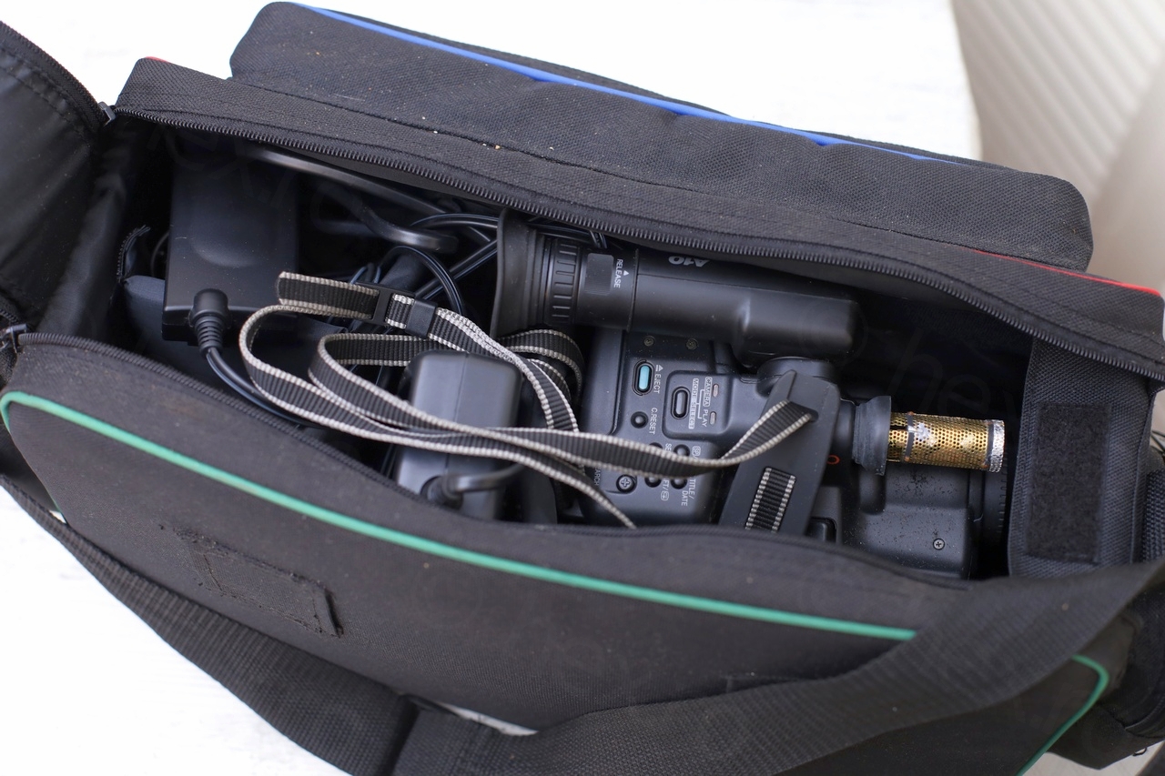
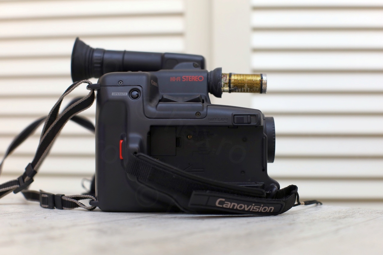
The camera bag contained some accessories (like a battery adapter, cables and an RF adapter) and all looked in pretty good condition:

I powered the camera on using its charger + battery adapter. Although there were signs of life, the green LED came on and the tape eject was working, the viewfinder did not turn on.
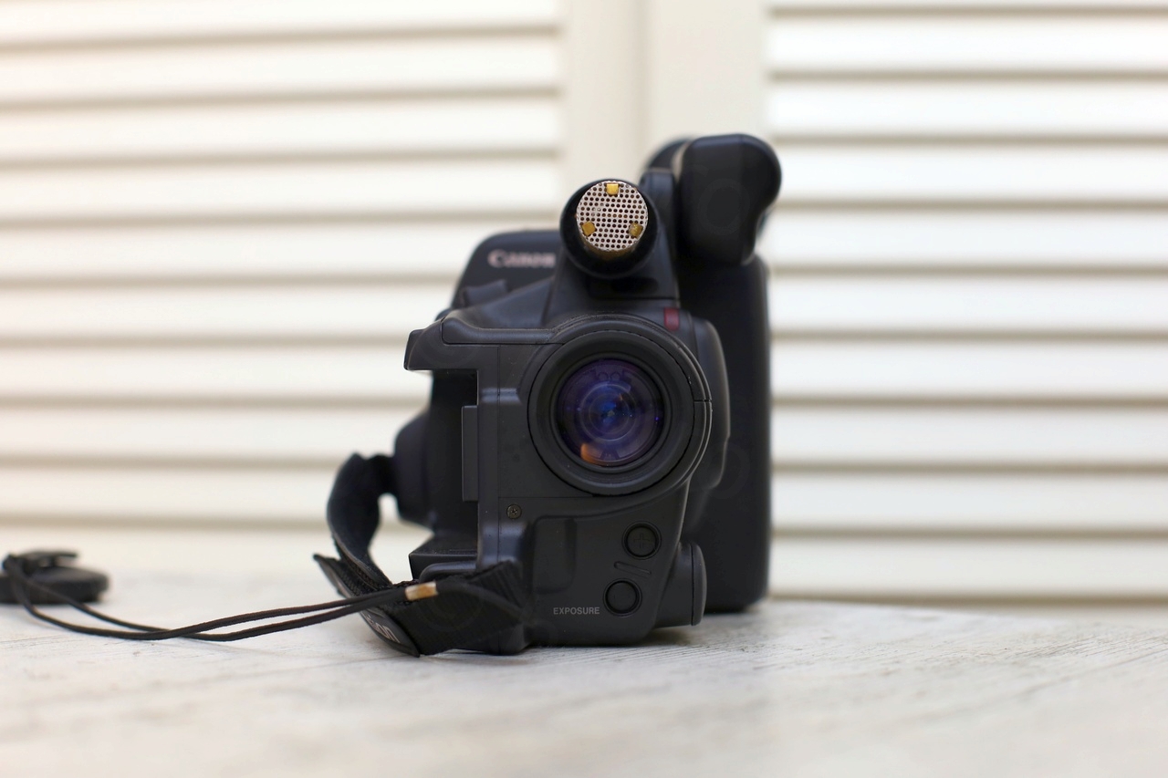
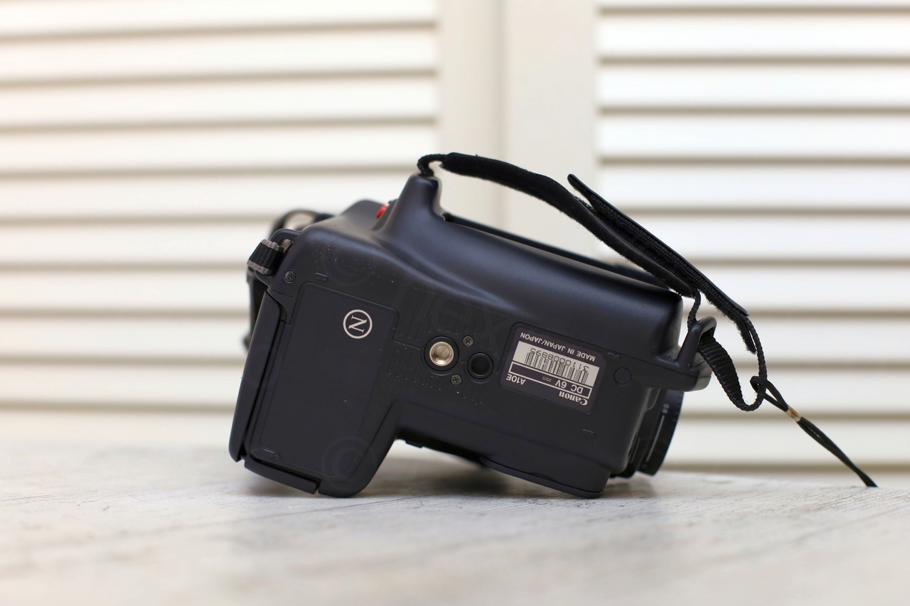
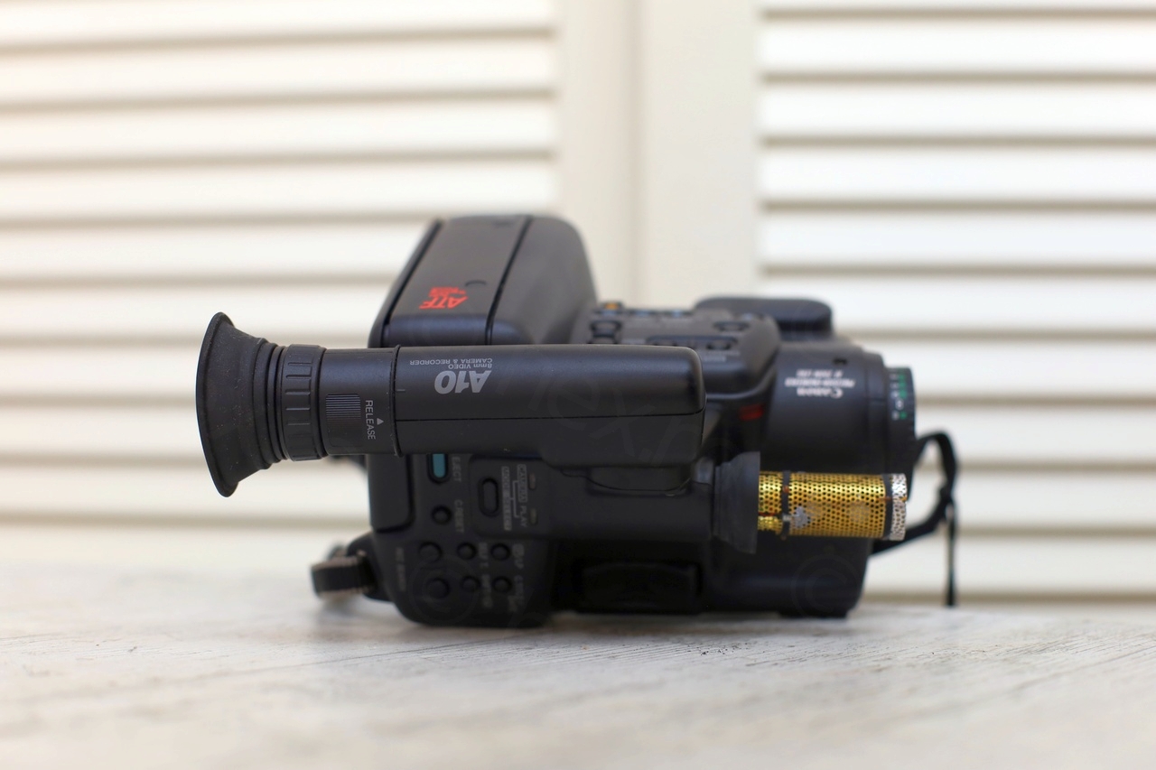
Few photos with the camera before dismantling it:

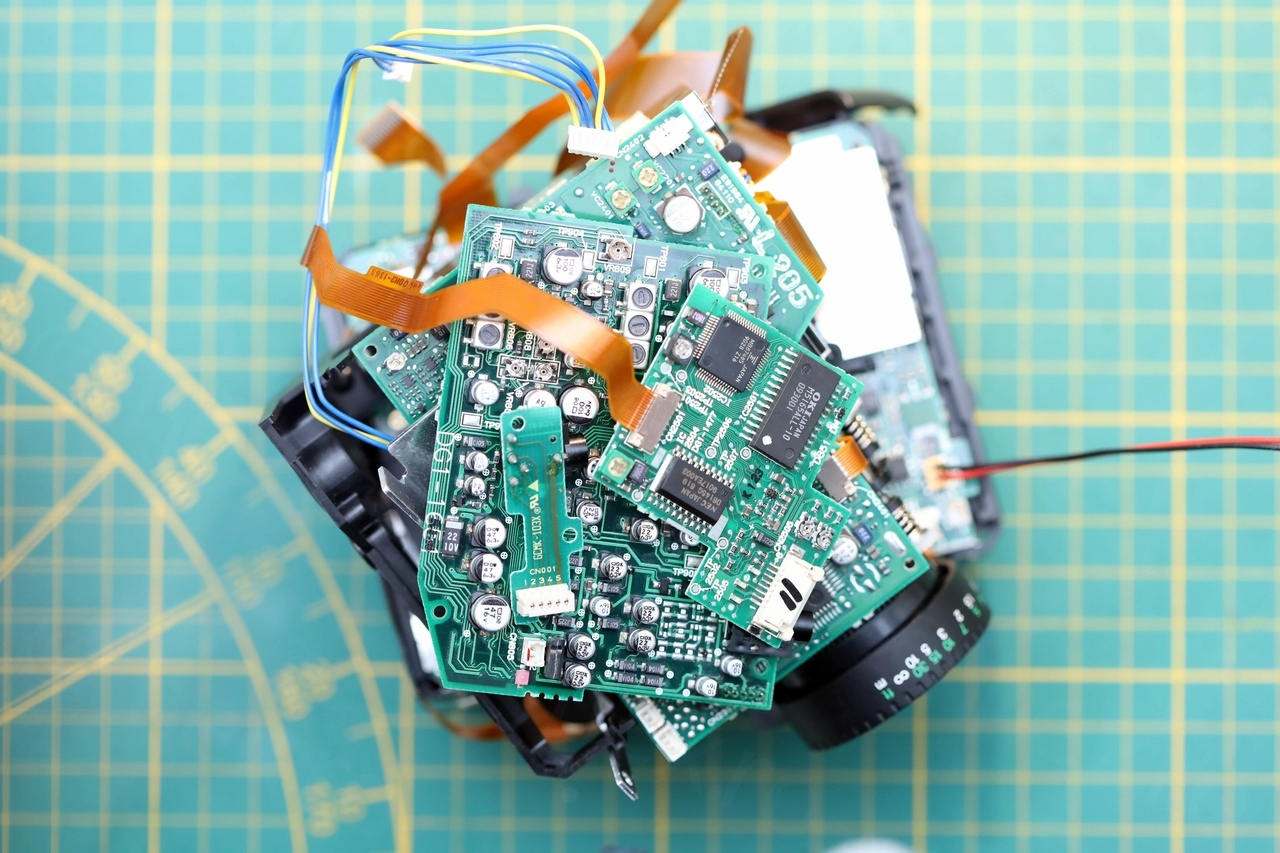
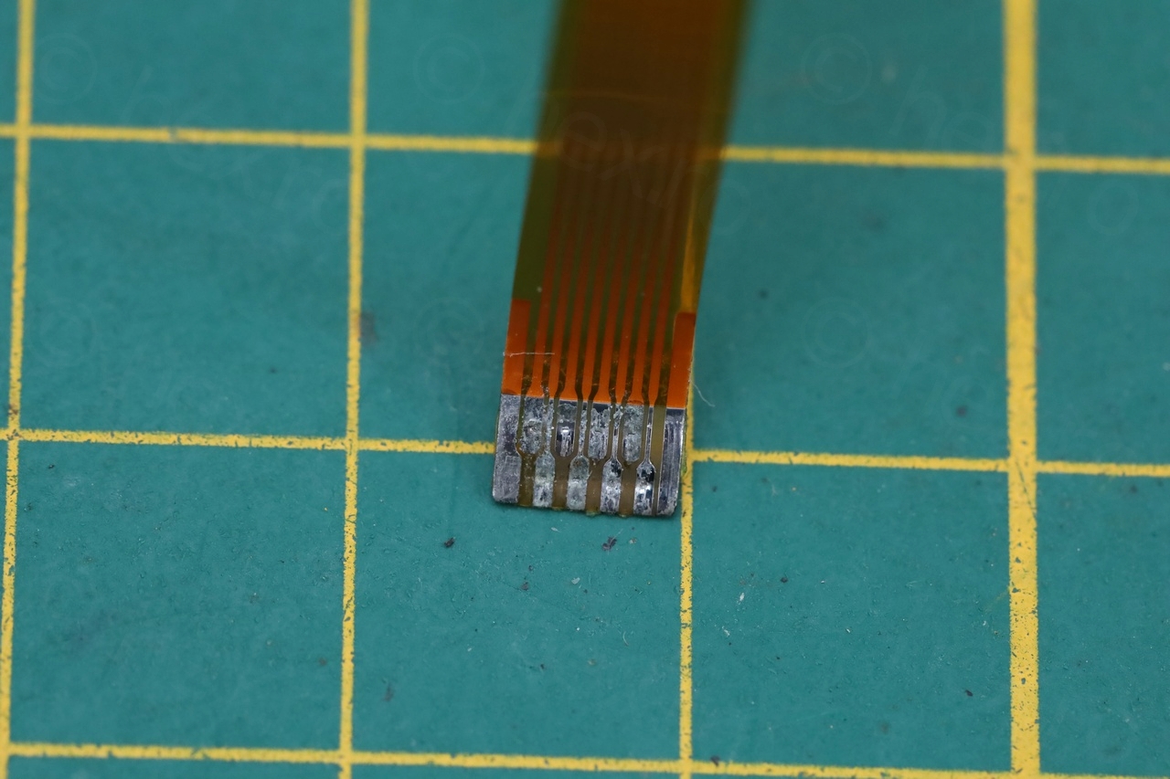
I proceeded to take the camera apart (which was rather easy) but troubling signs were already showing up. The view finder was connected through a flat cable and the side of the flat cable that was going inside the EVF was very corroded …

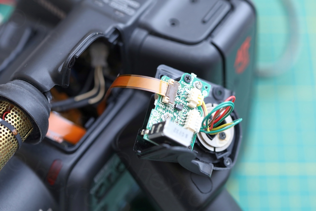
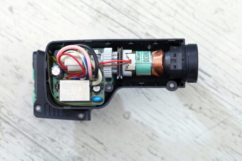
EVF Unit
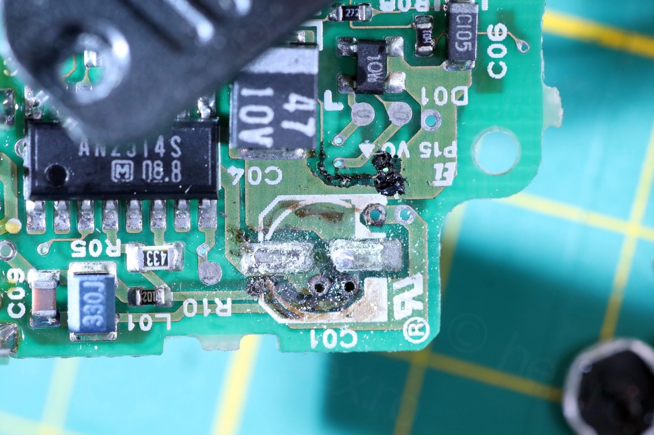
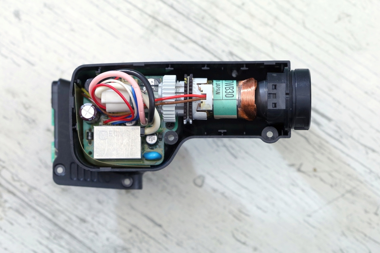
Opening the EVF Unit was a little more tricky, the two sides were very well clamped together. Also spotted a rubber ring (which may be for weather sealing), but the device looked clean and small. Driven by an AN2514S IC.
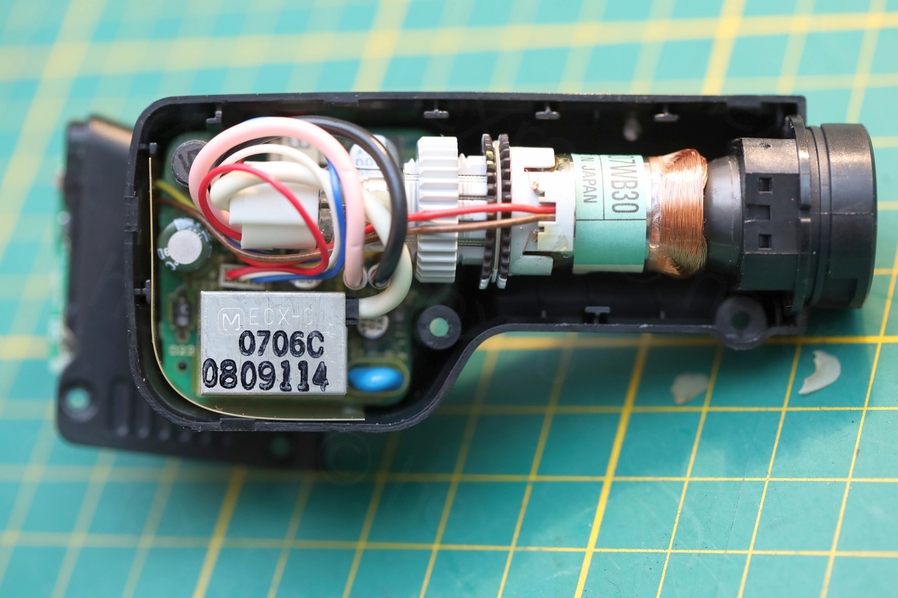
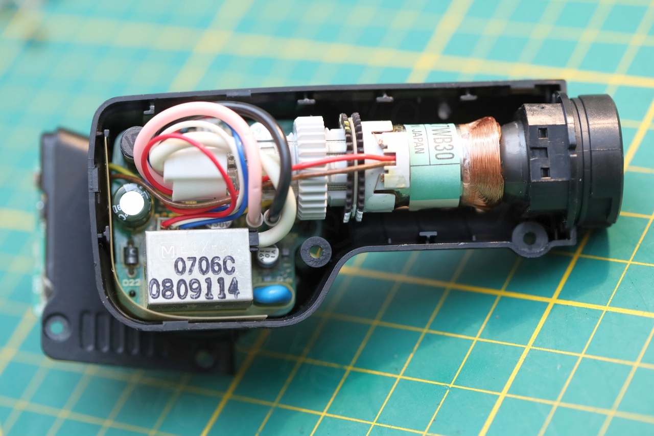
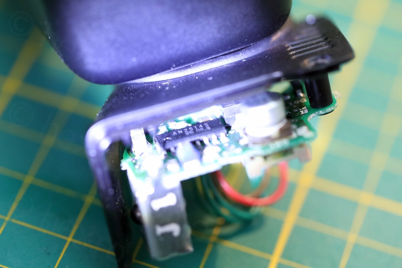
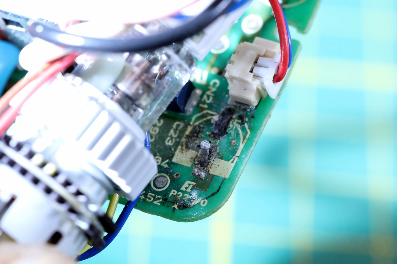
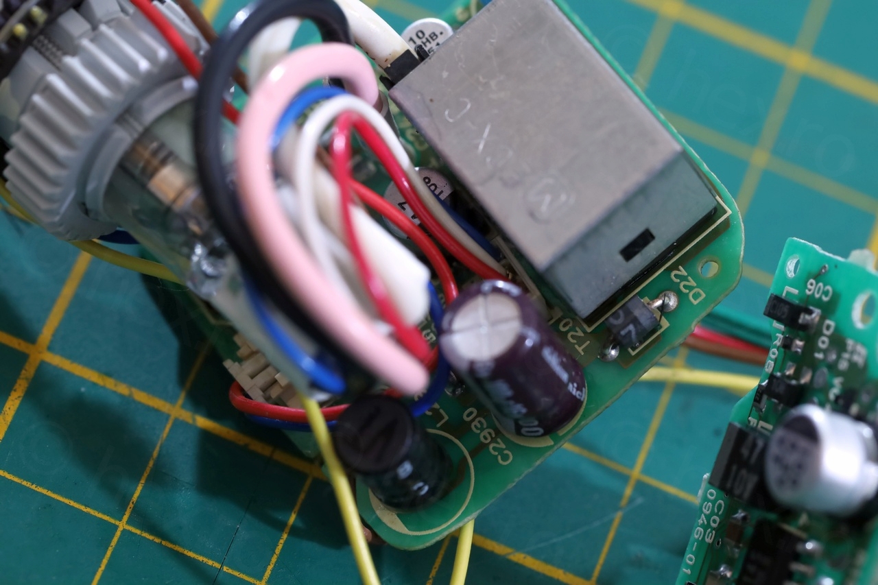
However, just a small look inside and yes, all electrolytic capacitors have leaked out, corroding their pads and even wetting the protection plastic that shrouded the inner board:
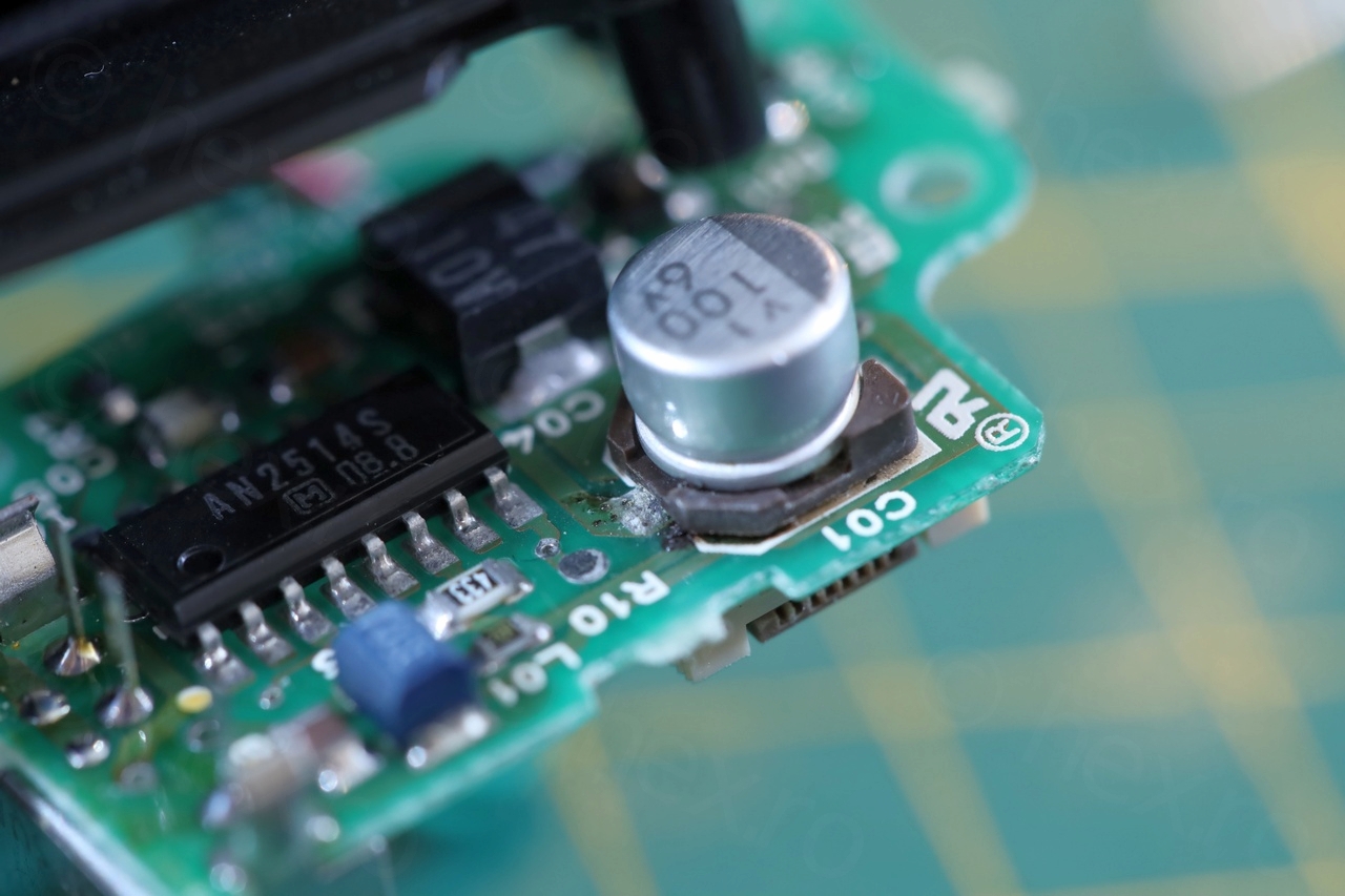
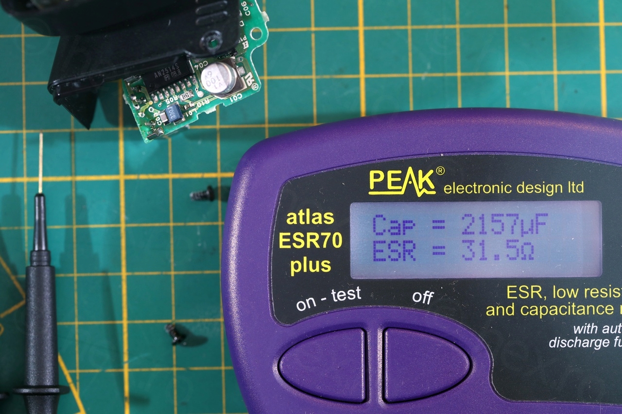


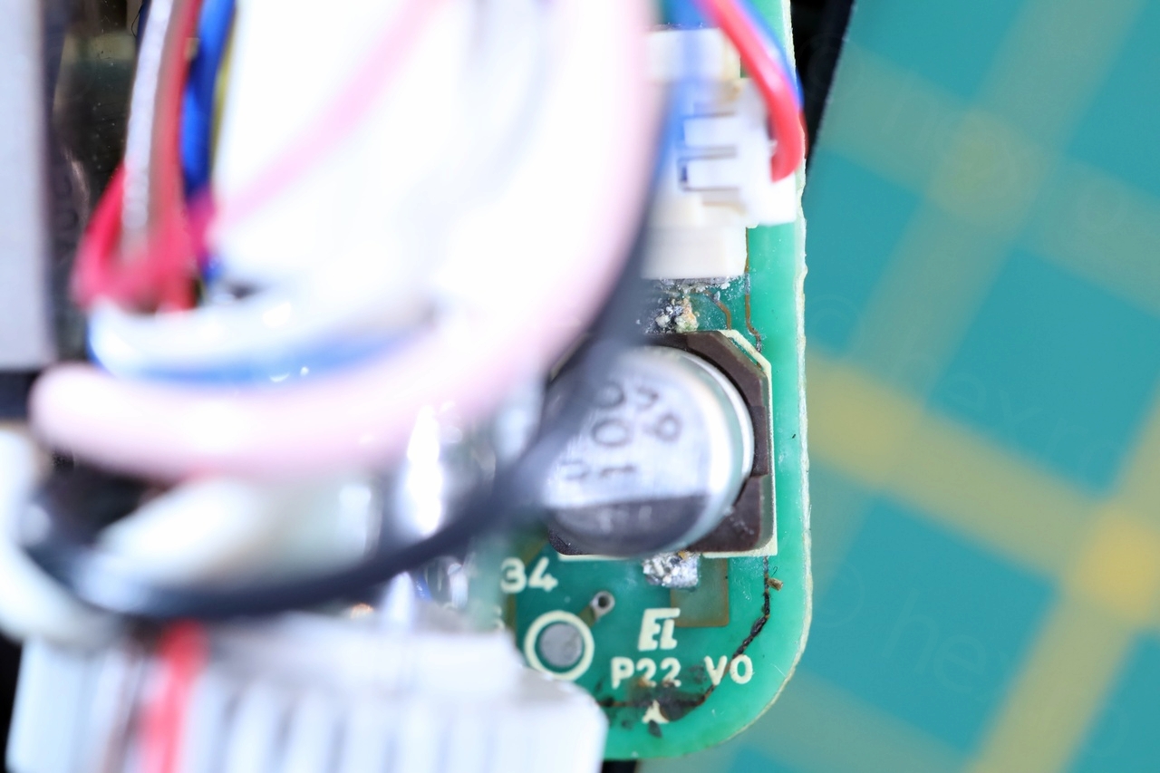
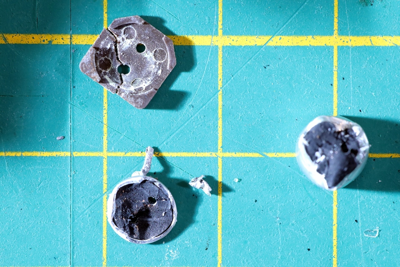
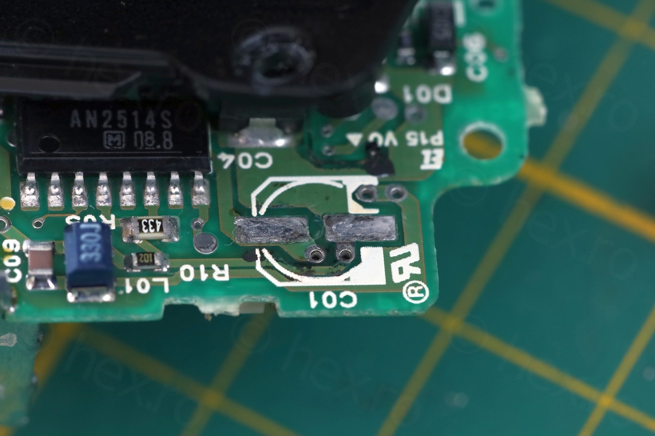
There were 5 electrolytic capacitors, 4 SMDs and 1 normal – all common values that I encountered in other cameras. I had replacements. I proceeded to cut existing ones apart then de-soldering the remaining leads. Cleaned the pads and soldered the new ones in.


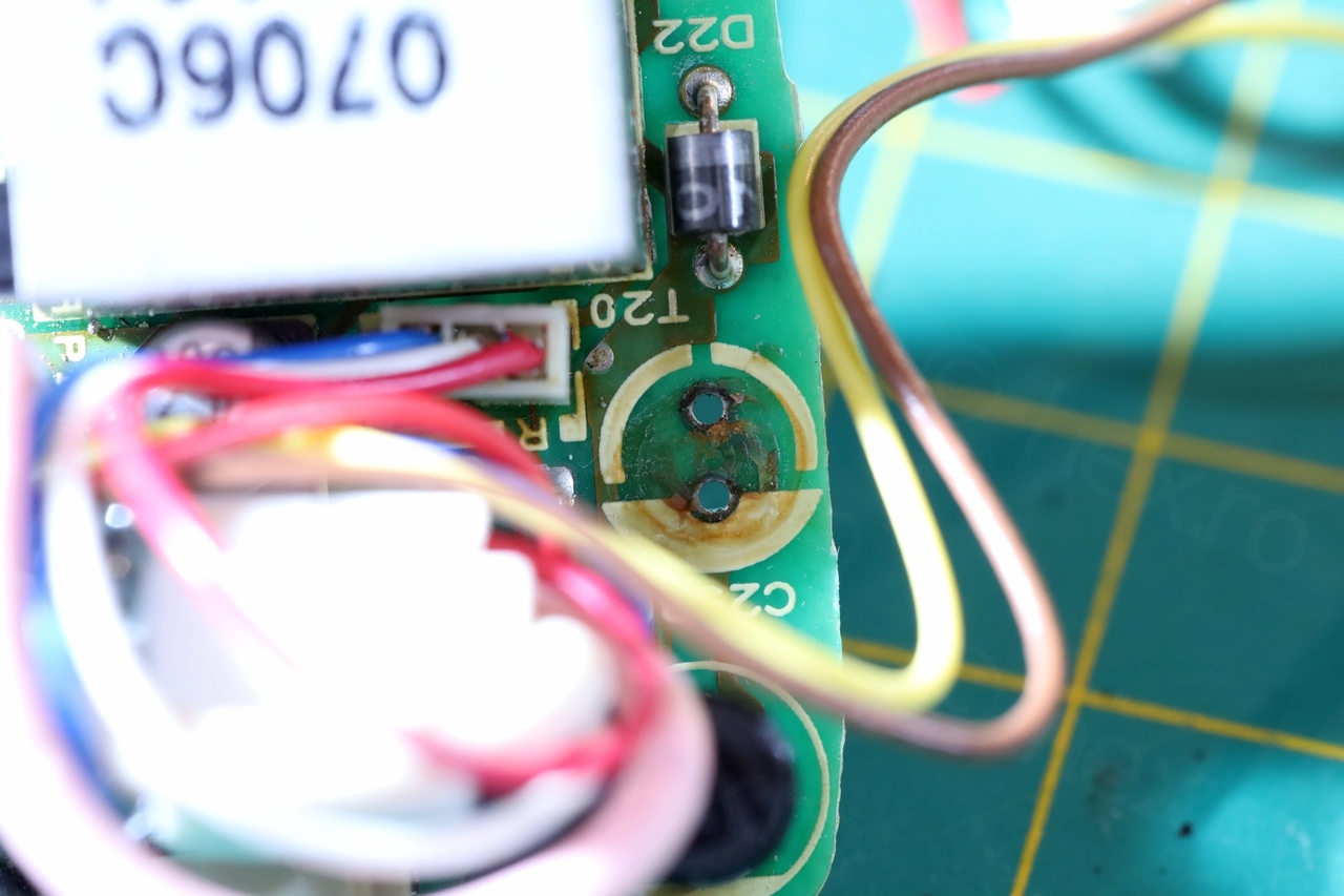

Unfortunately, replacing the capacitors was not enough. The CRT lit up – this was good – but brightness was unstable, screen was flashing. Voltages on the board were all over the place (but watch out, very high voltages). The Brightness potentiometer was not responsive at all.
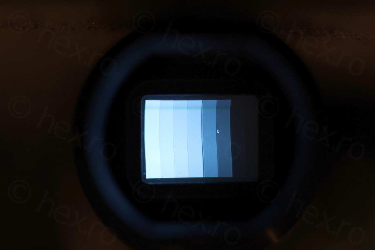
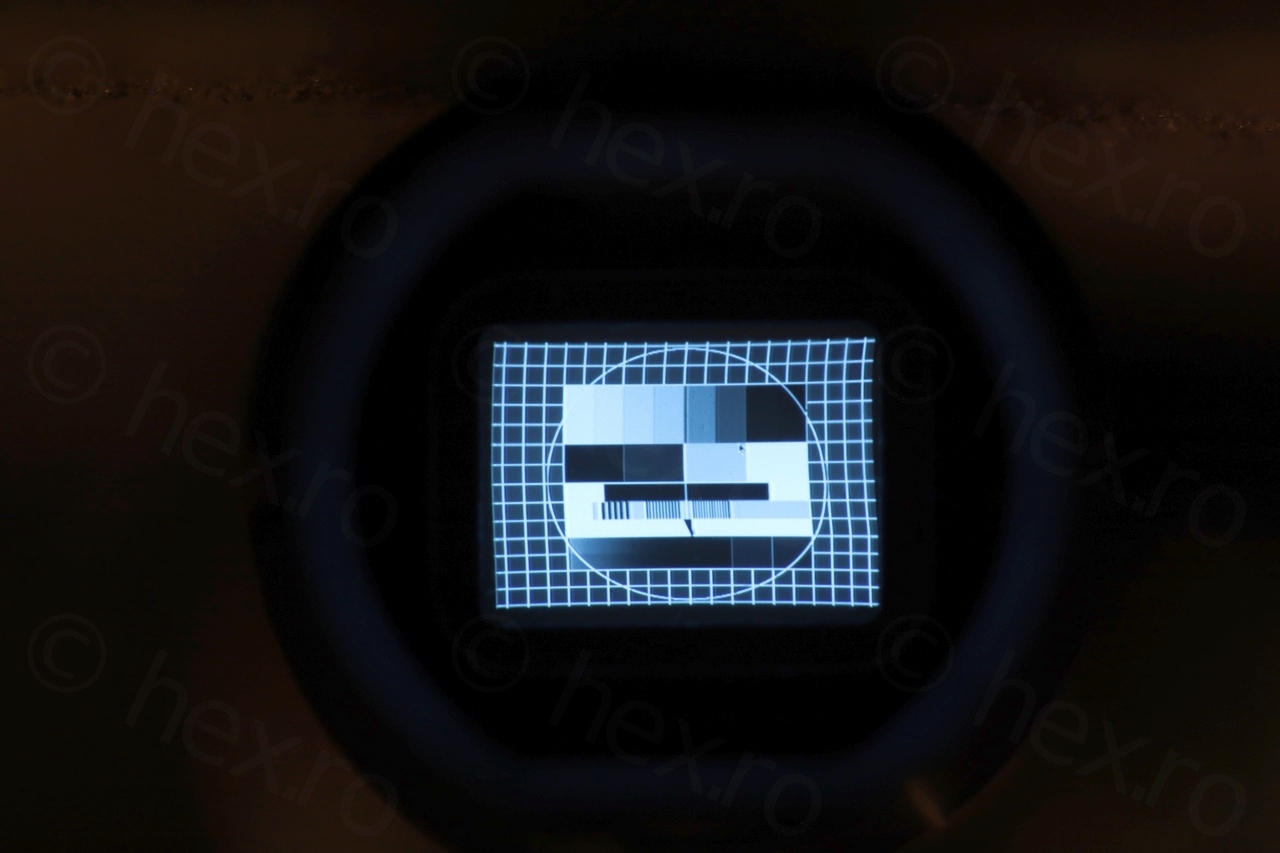
I decided to give the board a thorough wash with Isopropyl alcohol and for the first time, the brightness potentiometer starting having some effect. But still unstable. After a second round of washing, the image became stable. The screen starts out of focus, but it gets sharper in a little while. Looks best at 5V where it draws around 90mA. It looks sharp, but is not very vertical:

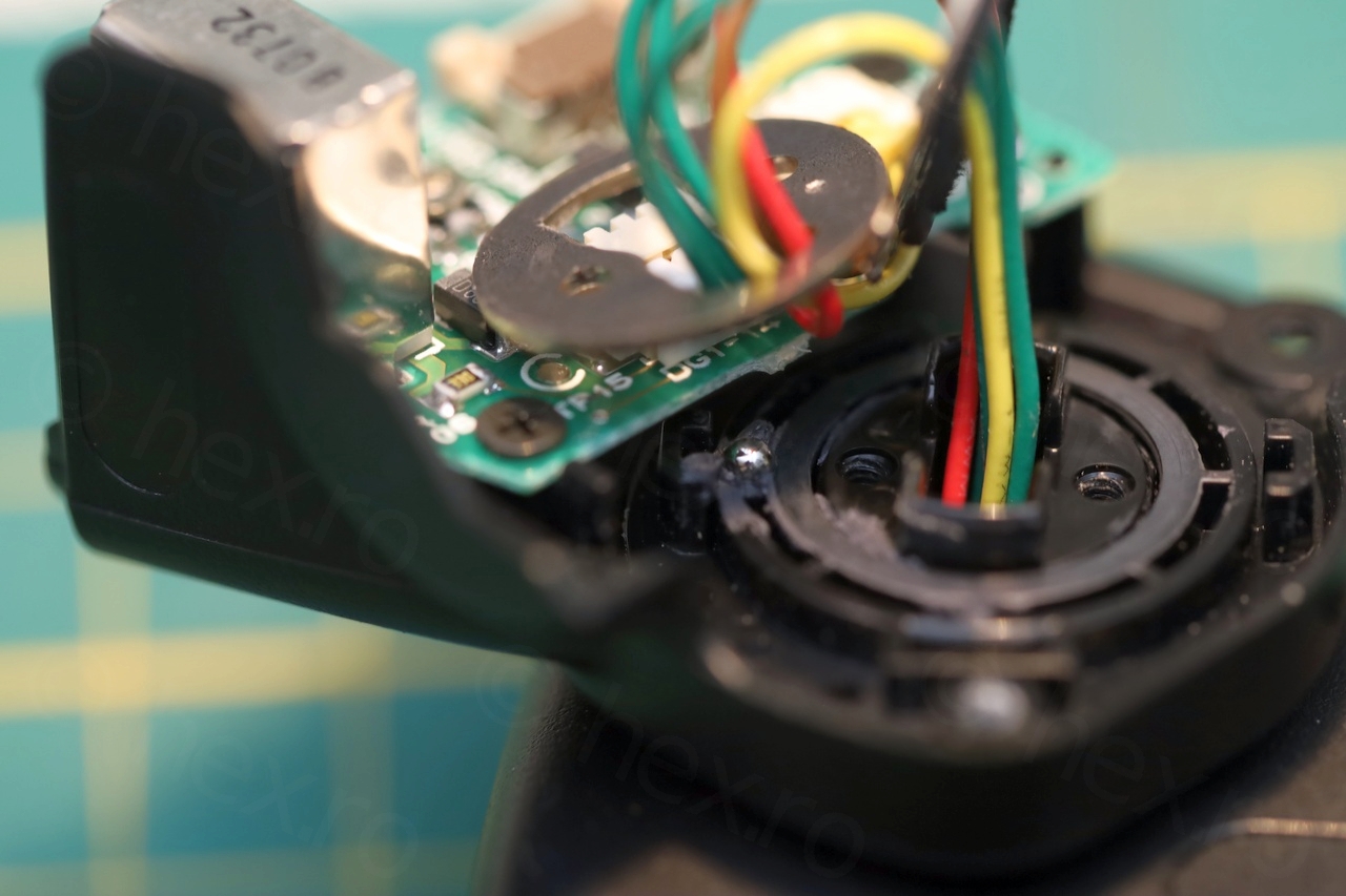
I have identified the signal wires – but I was not able to use the flat cable due to it being very corroded.
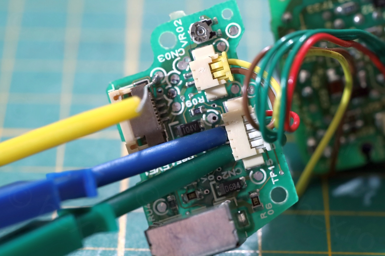
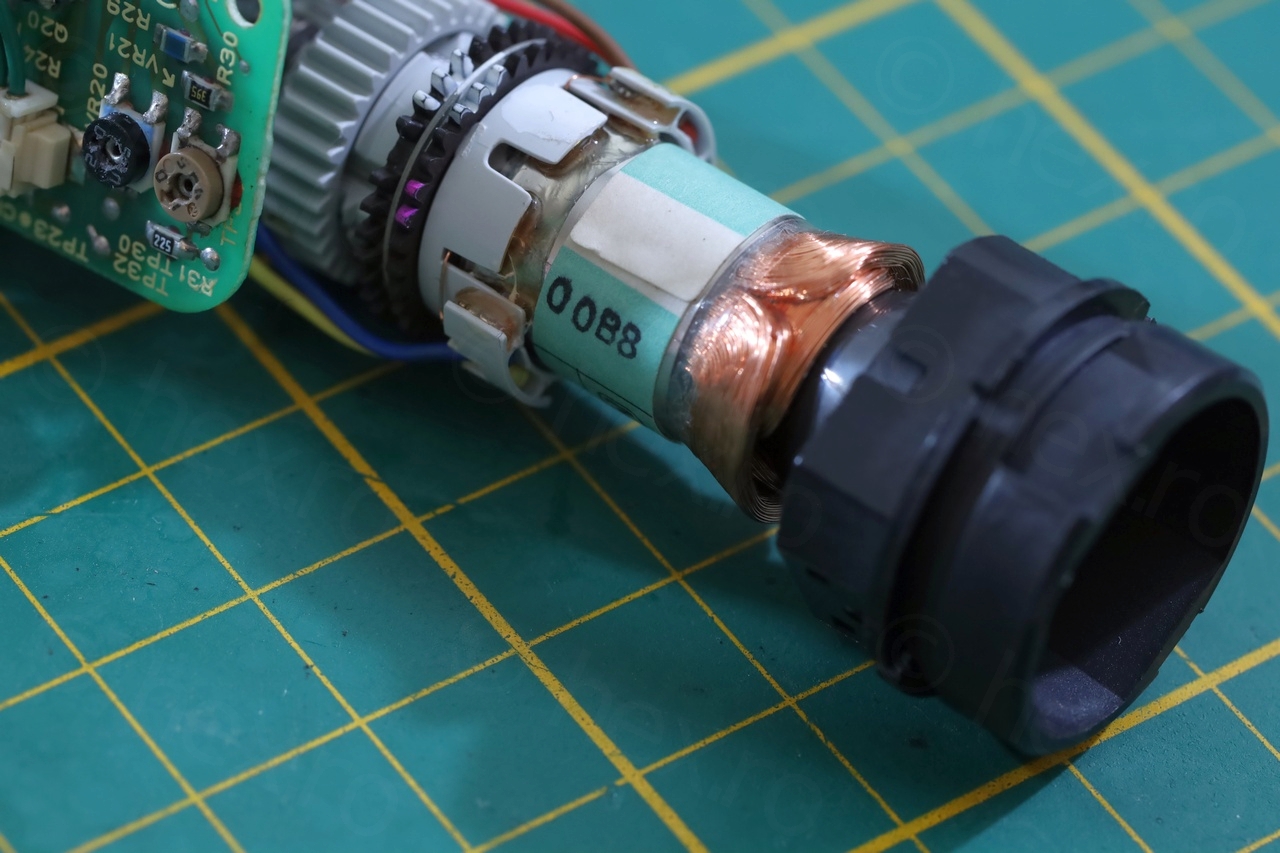
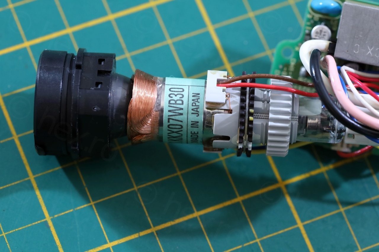
Few more photos with the CRT itself:

Except the capacitors needed to be replaced and thorough multiple washing of the board with IPA, I… liked the design. The viewfinder itself contains only the high voltage part of the board, while the driver IC (along with the InfraRed remote sensor) were on a separate board outside the unit.
Leave a Reply