


I found this CRT inside a Siemens FA 256 G4 video camera that I have bought at a flea market.
Table of Contents
- Introduction
- Opening up the camera
- Electronic View Finder
- Powering up the EVF independently of the camera
- CRT Test
- Conclusion
Introduction
Camera was small and I was impressed on how small the view finder was. It turned out to be that way because the driver board is not housed inside the Electronic View Finder unit itself, but in the camera body.
Few photos with the camera:


I got a bit annoyed when camera did not react when powered from an external power supply. I could not find any schematics online. But was hoping that the Viewfinder driver board works, without having to recap it.
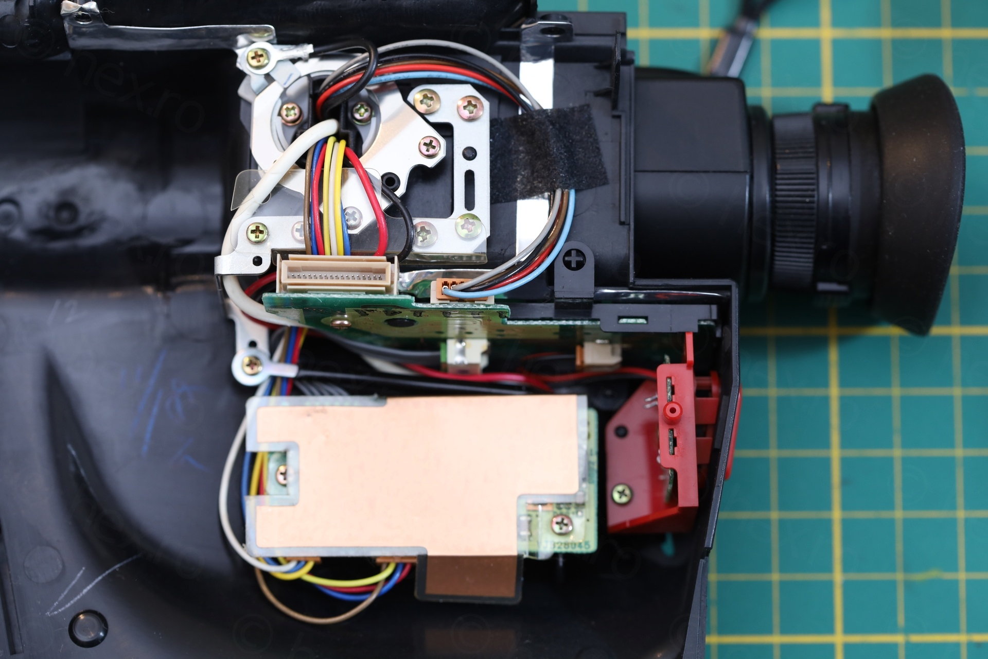
Opening up the camera
Siemens made it really easy to get into the camera, although I had no clue on how to rescue the captive tape. Eventually I was able to get to the small latch that triggers the mechanism to open, but not until I fully dismantled the camera.
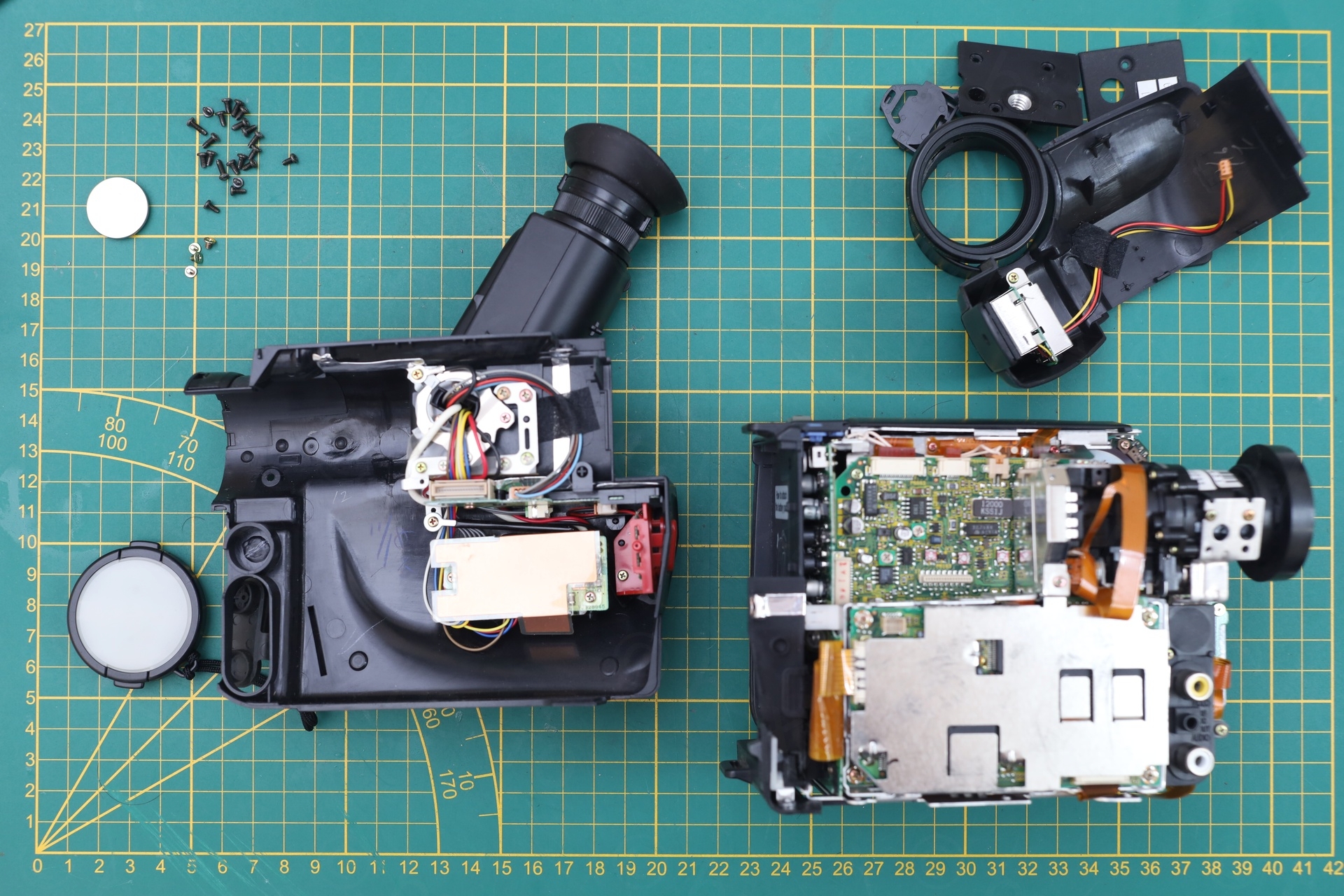
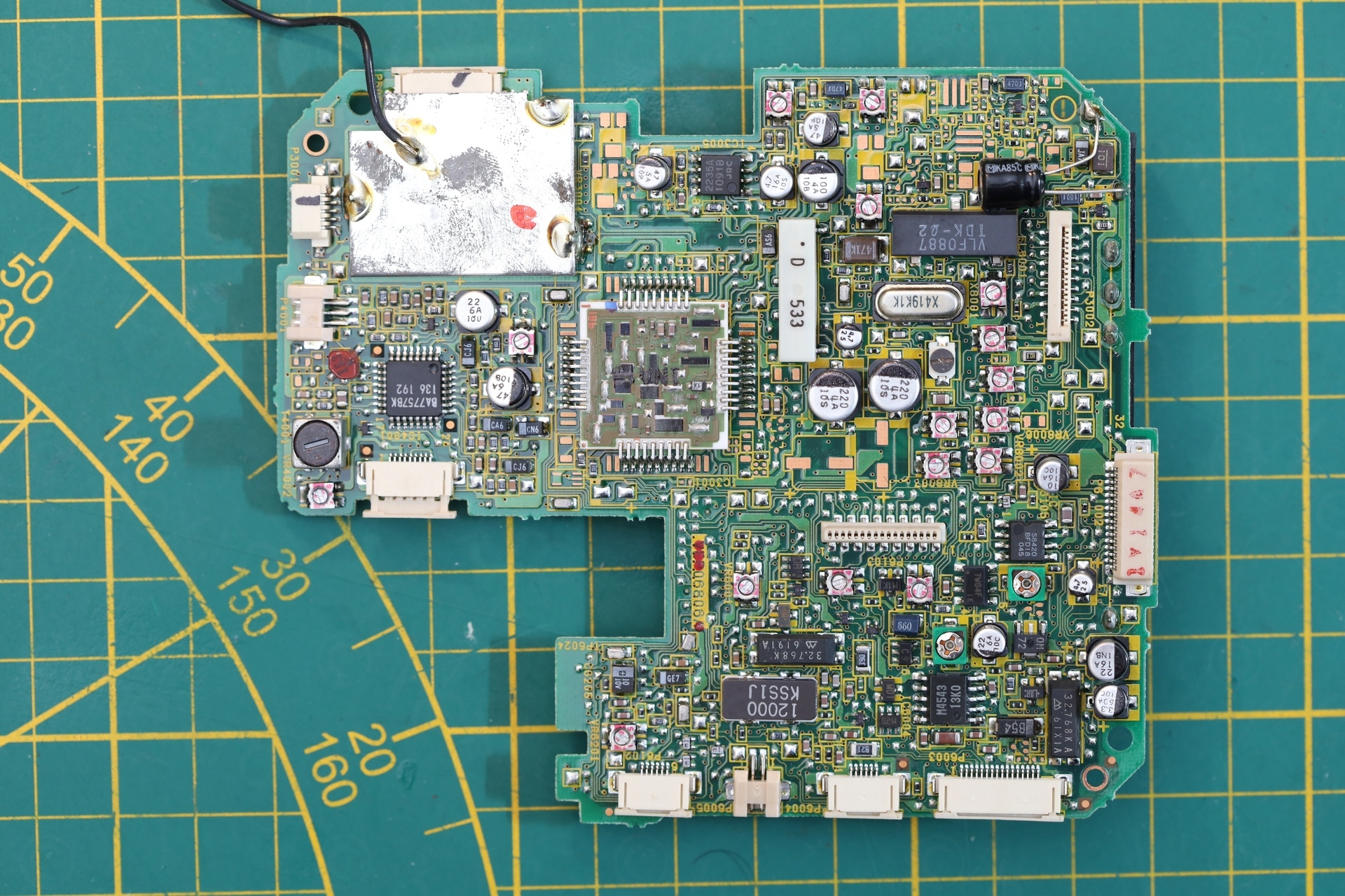
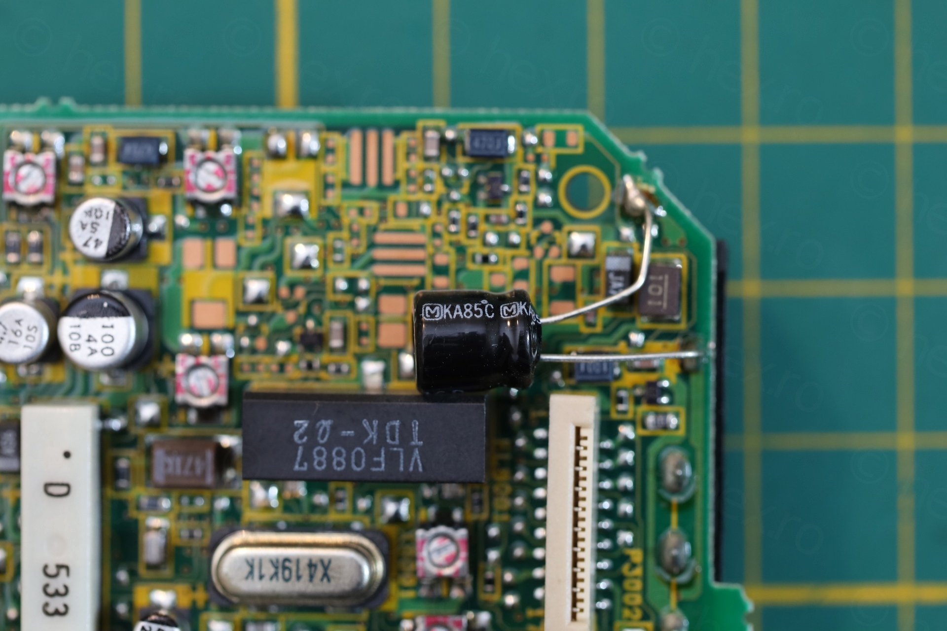
I spotted one small bodge, a capacitor on the top right of the motherboard, otherwise, nothing out of ordinary so far, except one screw that was a bit loose inside.
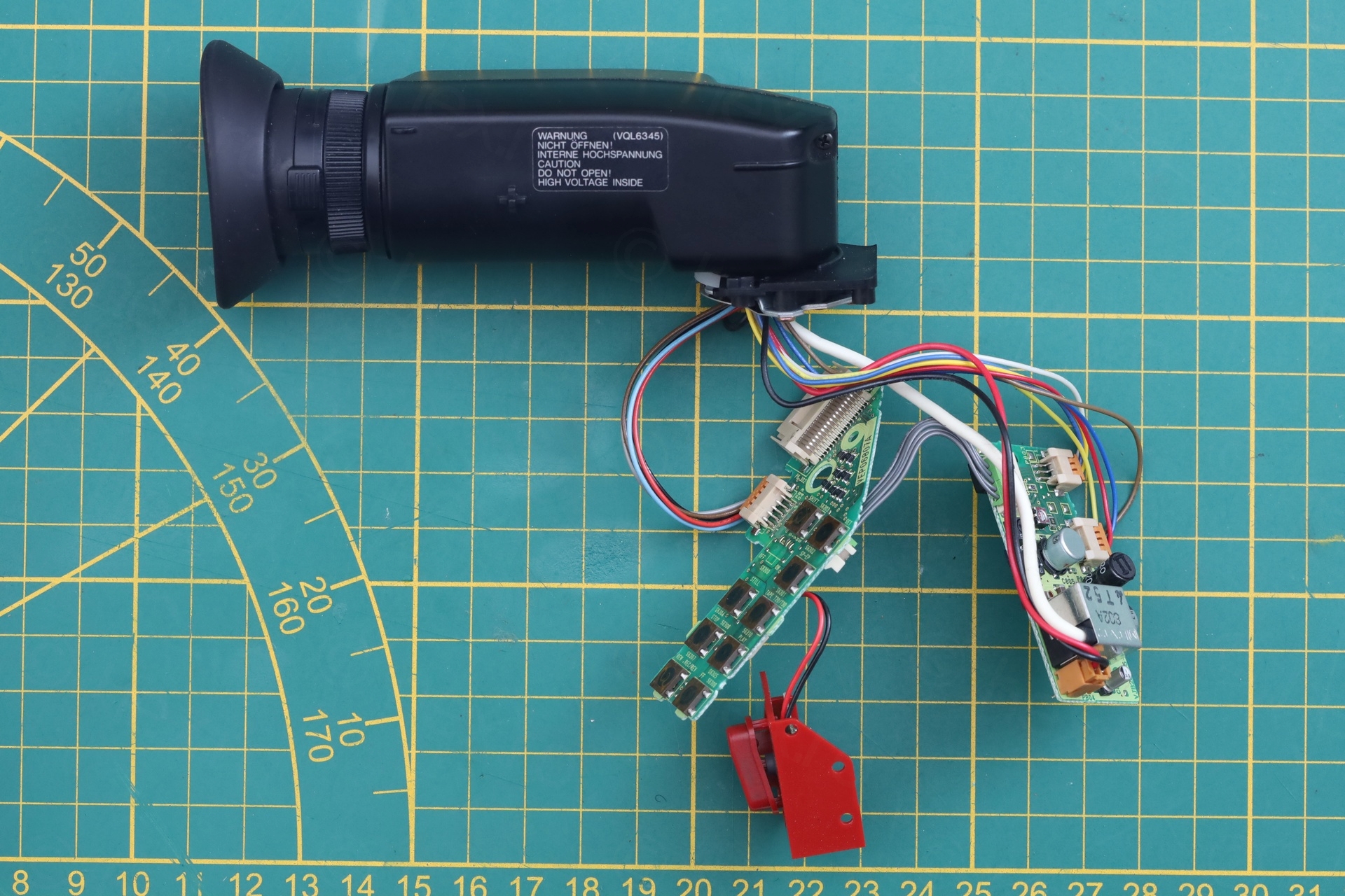
Electronic View Finder
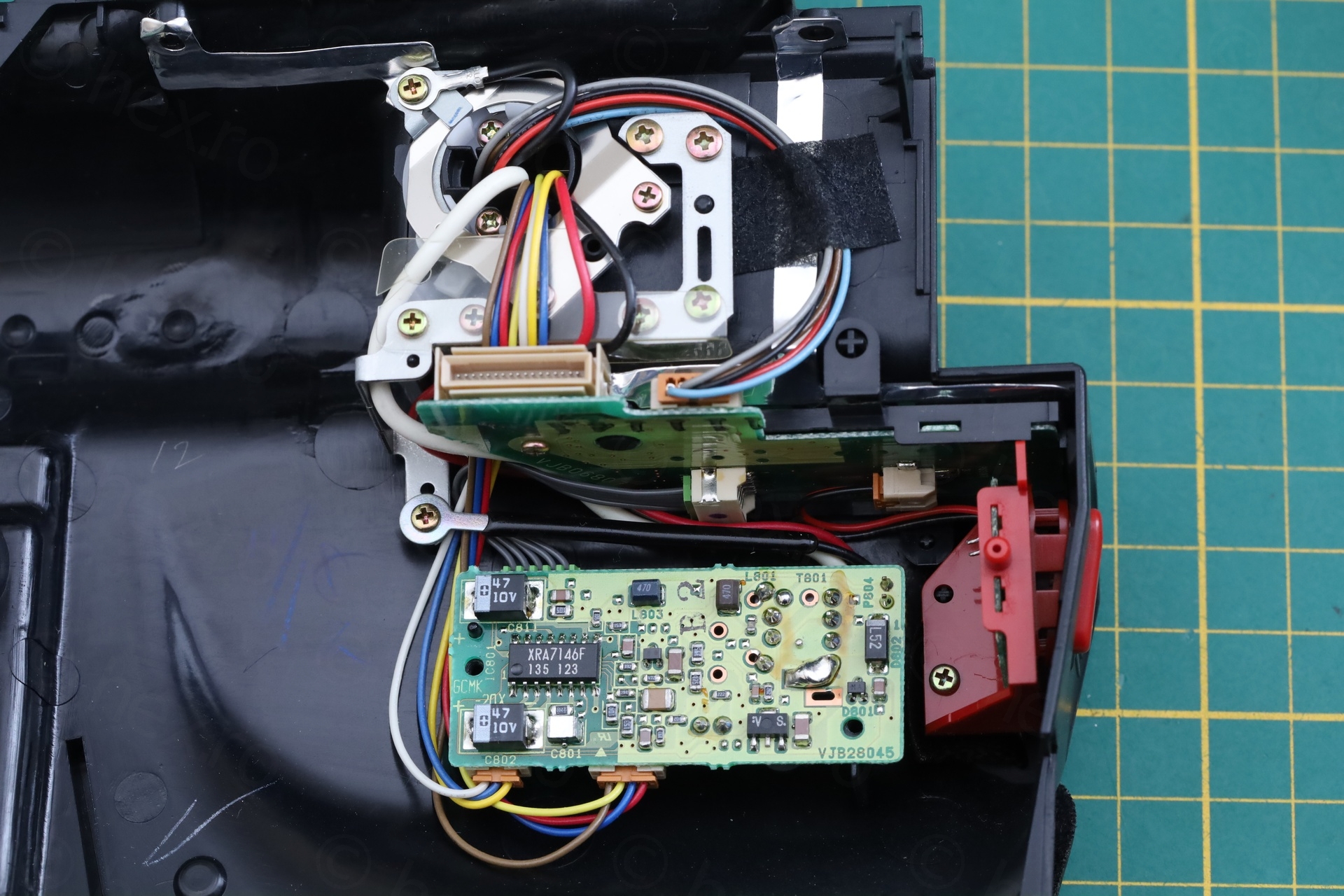
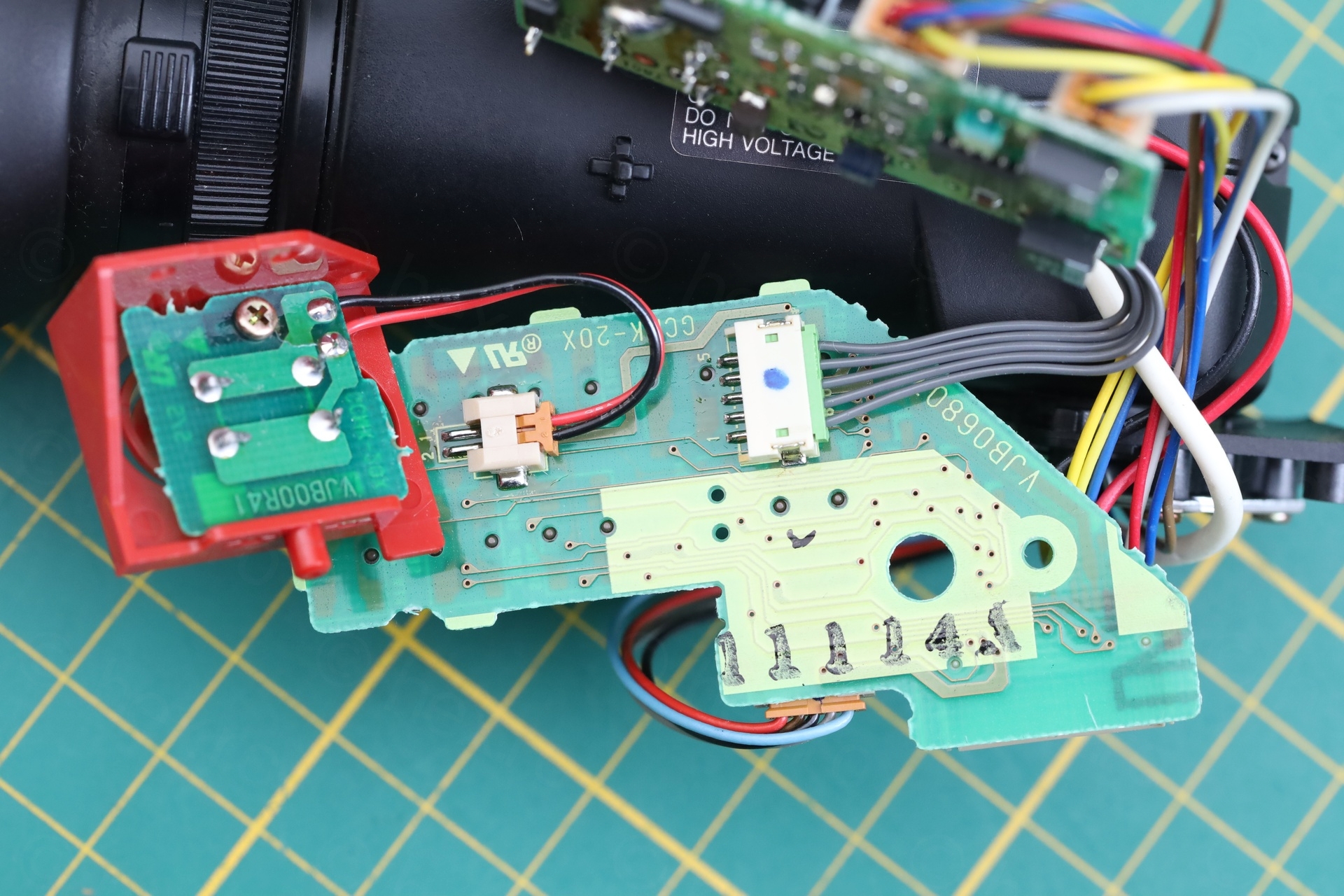
The EVF plastic did not house the driver board. It was “externalized” inside the camera body. This made it easier to try to power it on without having to take apart the EVF unit itself, although I eventually did, just to see what CRT is inside.
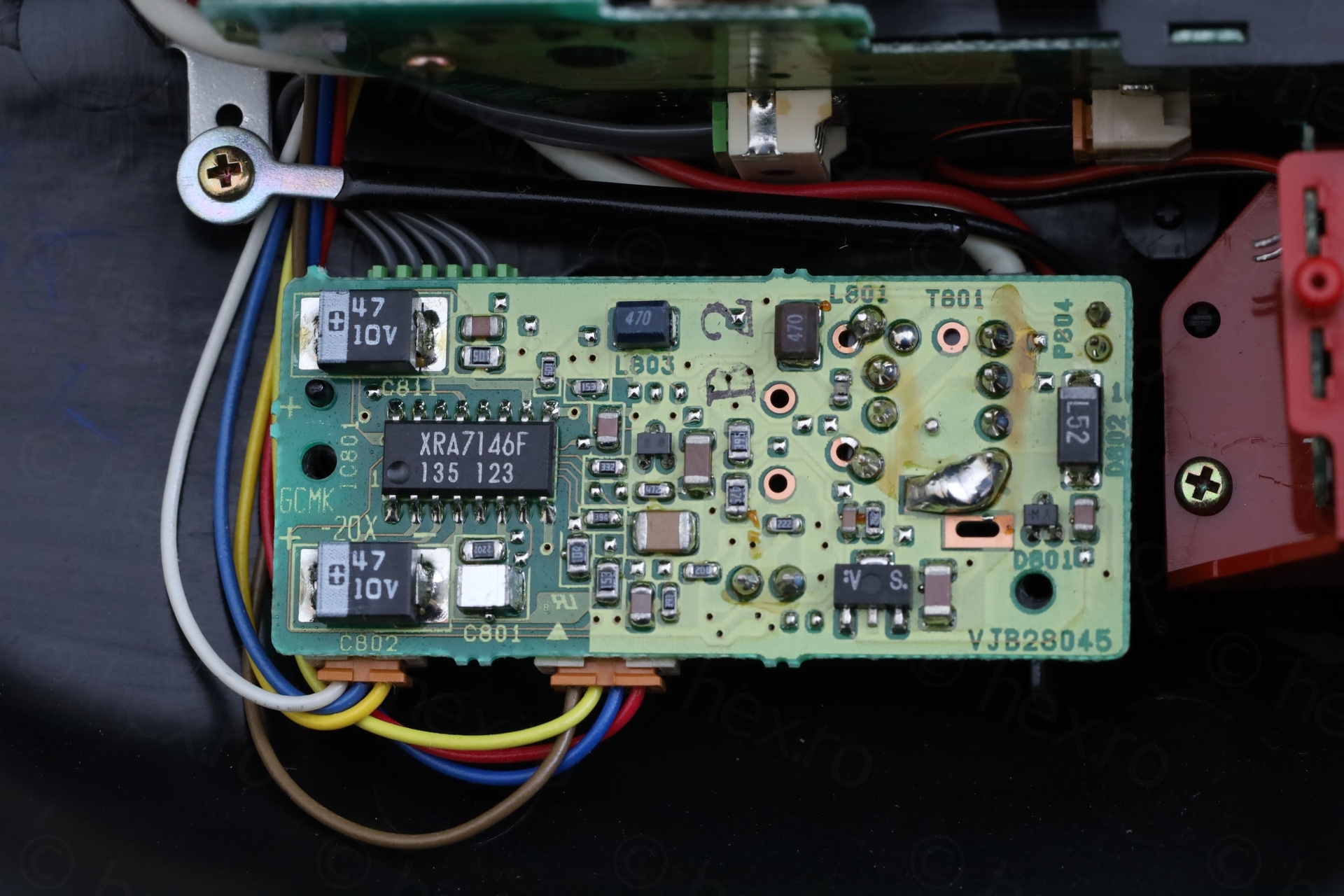
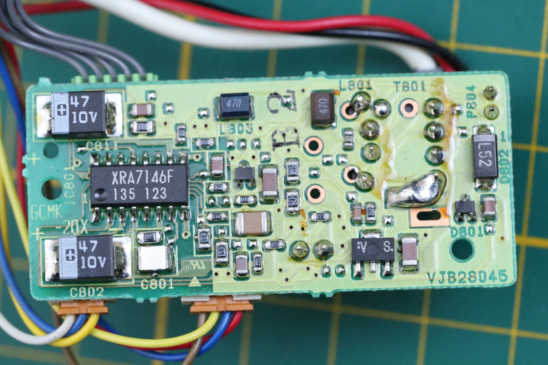
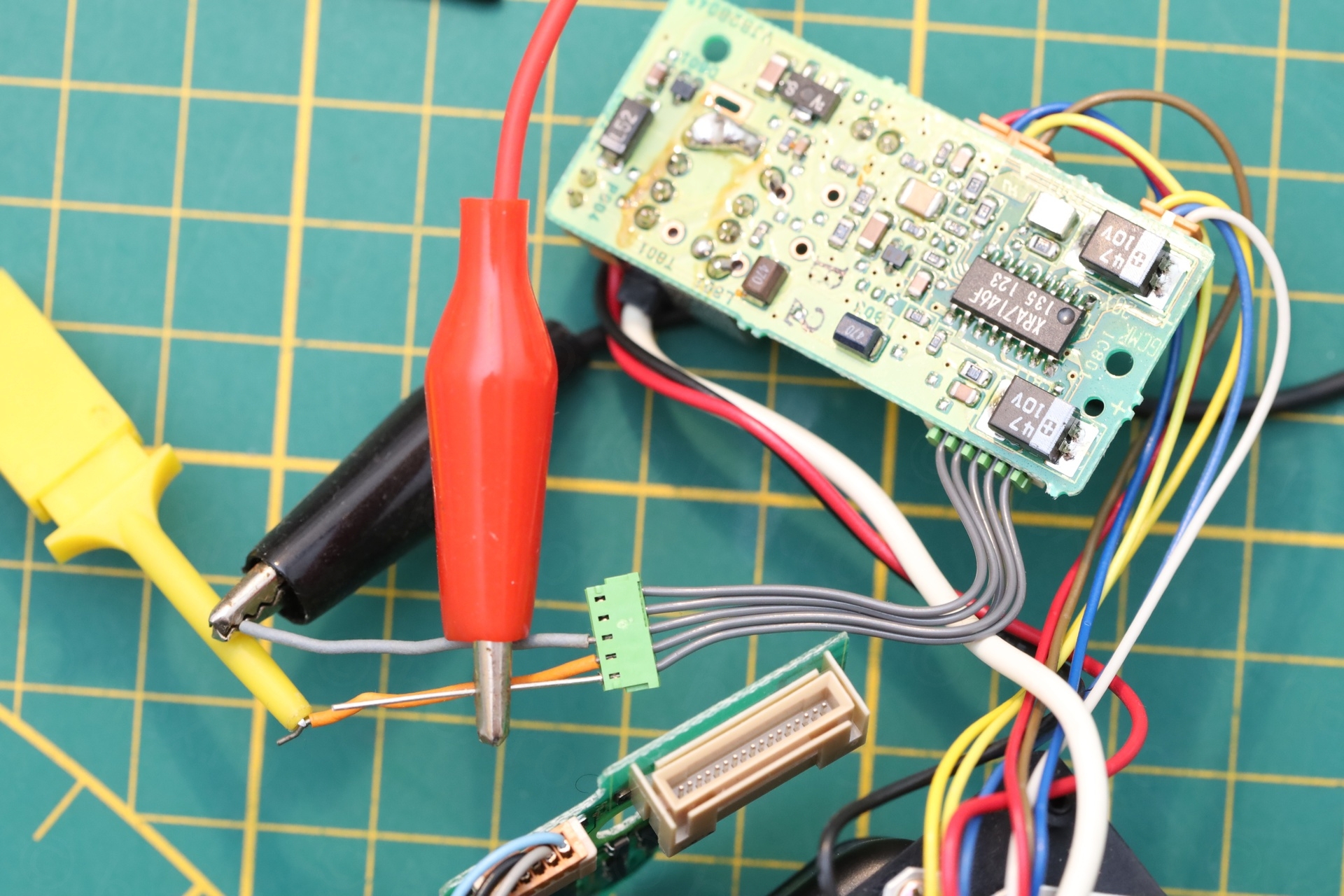
XRA7146F is the driver IC. This is the first time I encounter this one – so it was a nice finding. There were small traces of yellow compound, that seemed to have ran down towards the board. I wondered if this is a leak from a capacitor that was sitting just close to the Flyback Transformer ?
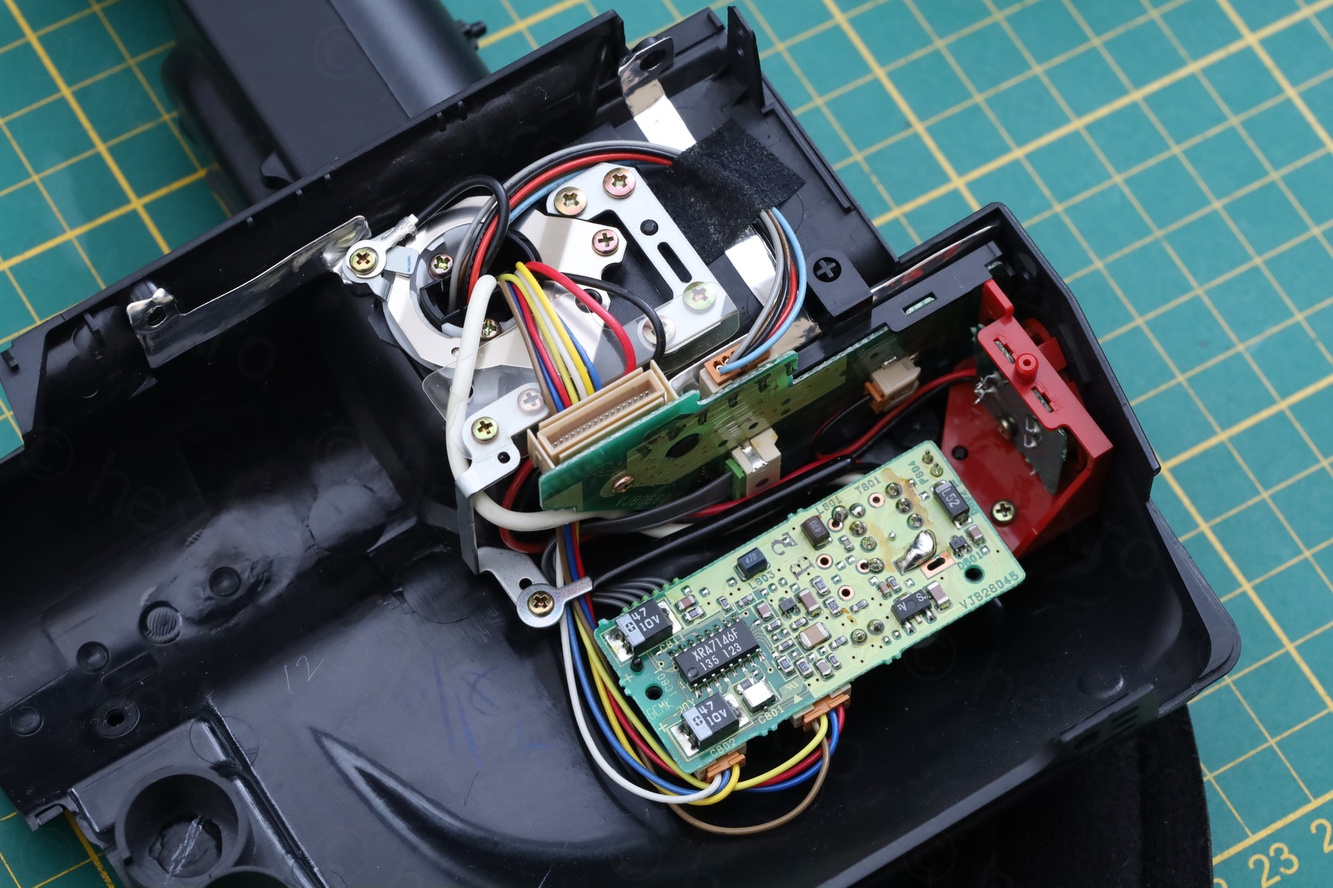
Powering up the EVF independently of the camera
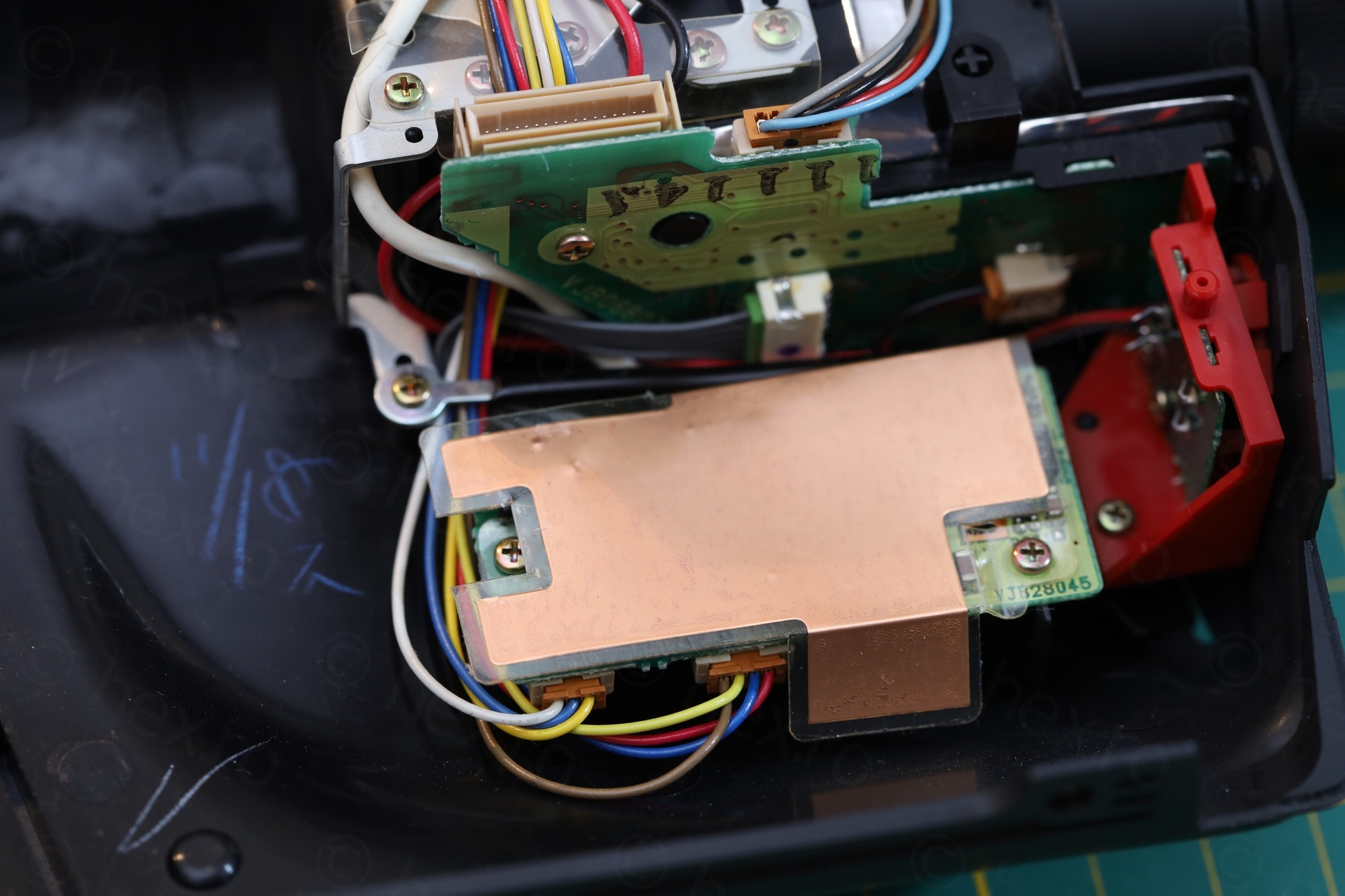
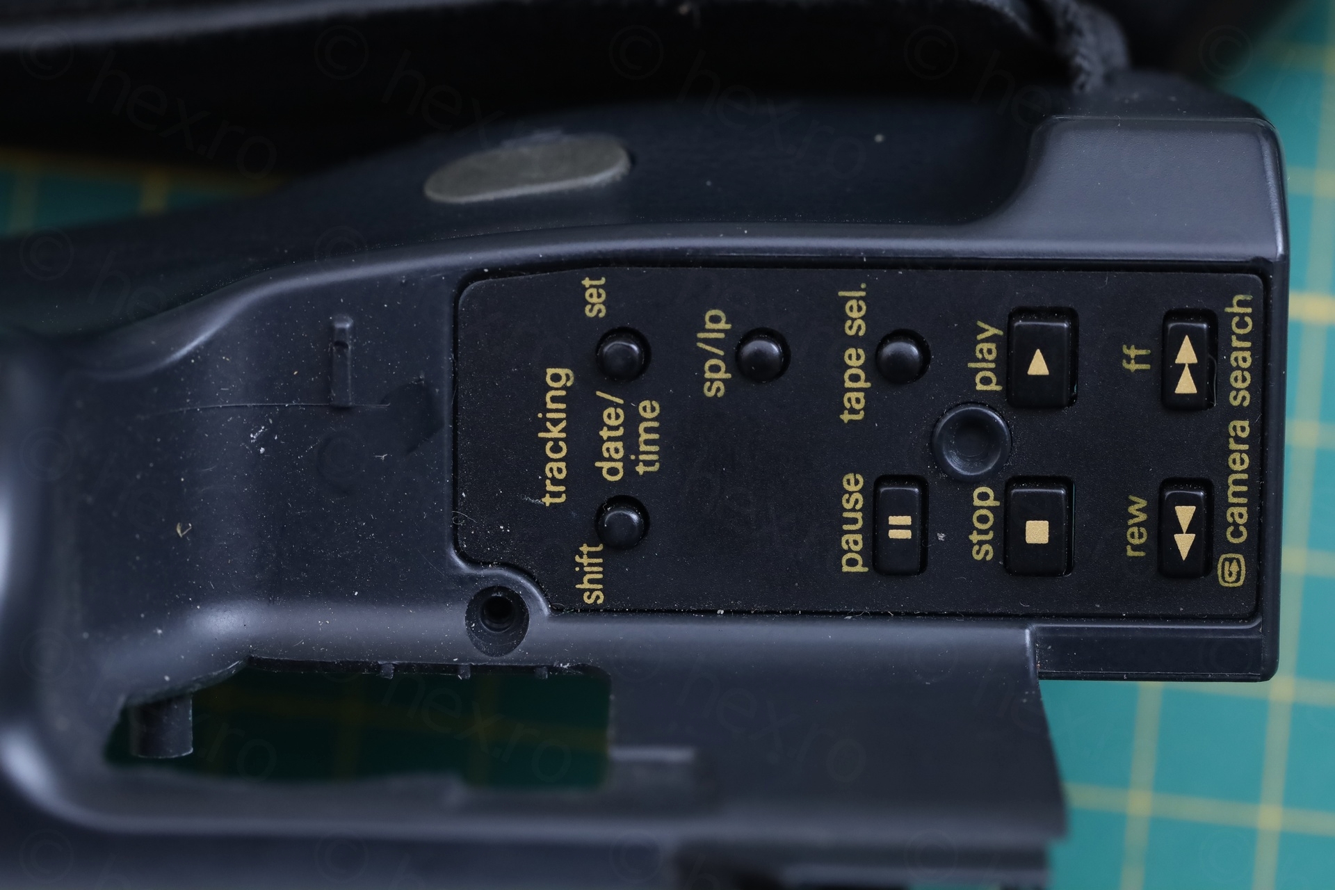
The EVF was connected to an intermediate board that was housing small tactile buttons found under the EVF outside the camera:

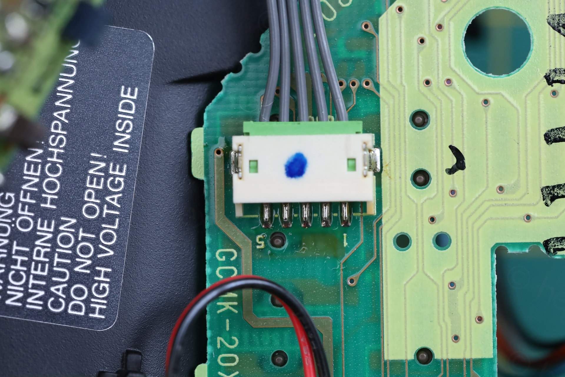
It was easy to tell apart which wires were for the CRT and which ones were for the buttons though.
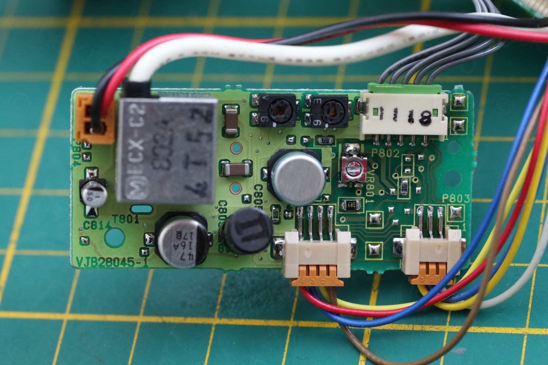
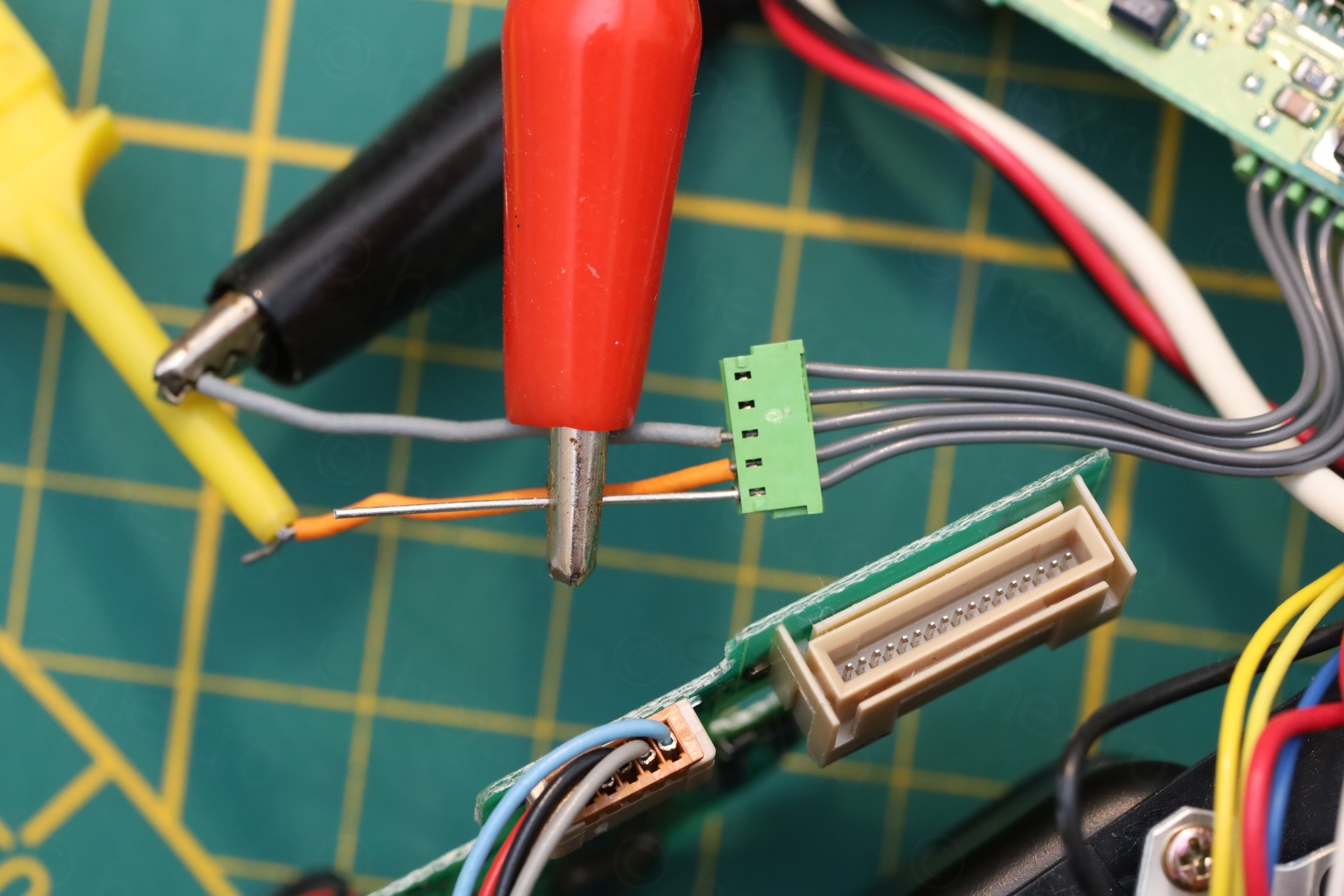
After testing continuity between the Flyback Transformer outer casing (usually connected to Ground), I located one of the 5 gray wires that represented GND. It was the middle one. Then, some of the pins of the FBT are also connected to VCC, thus, with meter in continuity mode, I was able to locate the other pin that is VCC. After a bit of trial and error, I also found the Video IN pin:
CRT Test
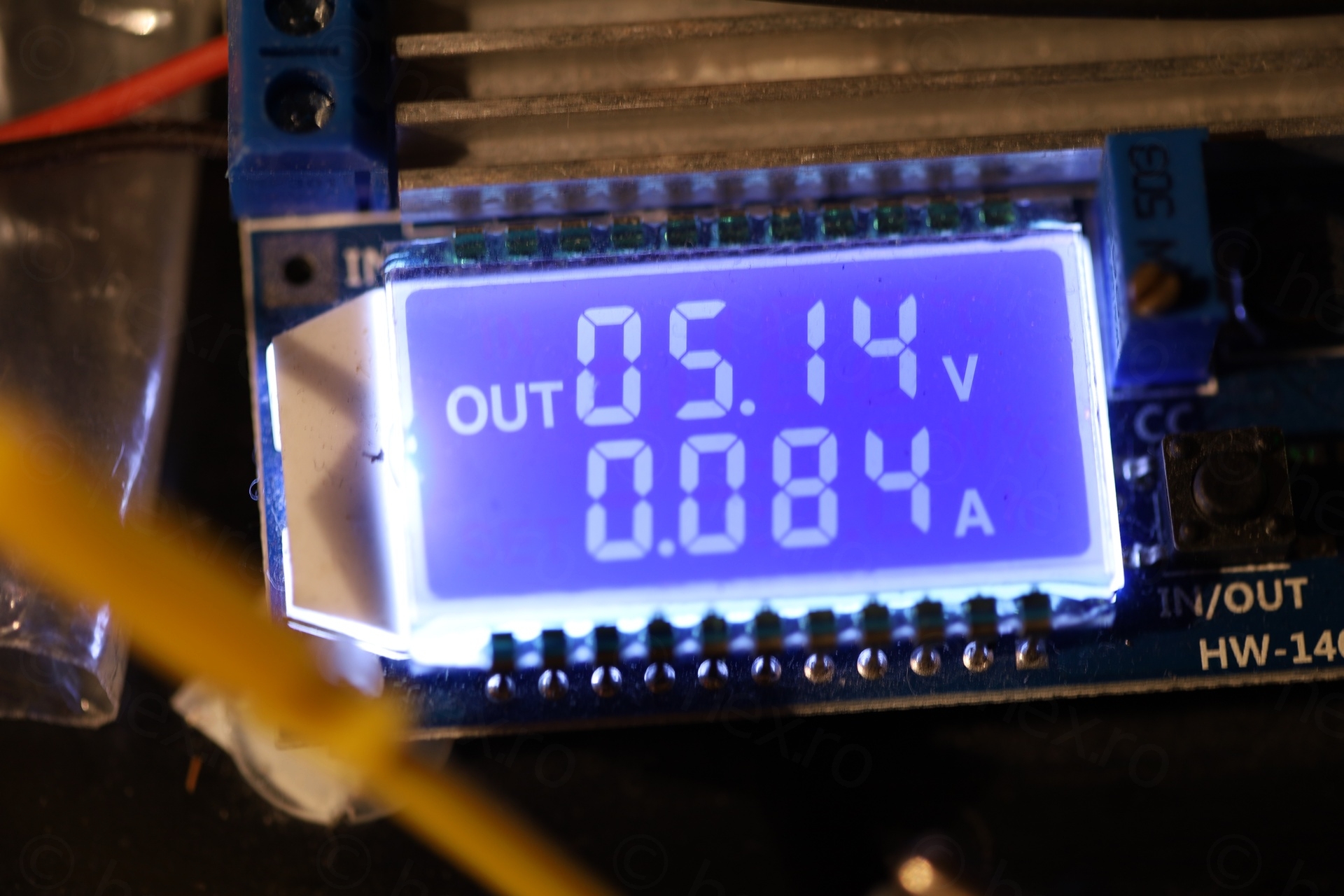
Usually, once VCC and GND are applied, there will be a faint illumination of the CRT (but not necessarily faint, depending on adjustments probably), maybe even a little flickery. Not here. Applying VCC and GND does nothing (except drawing about 80mA of current). Initially I thought I did something wrong. Maybe not identifying the pins right. Only after trying Video IN, that the image appeared.


M01KKX07WB05 – Testing
Conclusion
First time encountering this exact CRT model and driver IC. EVF draws about 85mA at 5.2V. Unfortunately, I have packed the EVF already, but I am having second thoughts. Maybe if I would have replaced the capacitors, then perhaps the image would not be so distorted ? I’ll make a note and come back to it later …
Leave a Reply