


Found this mini CRT inside a Sanyo VM-ES88P Video Camera that I found strolling through the flea market.
The camera caught my attention its flatbread aspect (or maybe, a turtle aspect). Flat. And it looked like it might have had a CRT inside, the price was right, so why not.
Table of Contents
- Camera overview
- Opening the Sanyo VM-ES88P
- Opening up the EVF Unit
- EVF Unit does not power up
- Testing
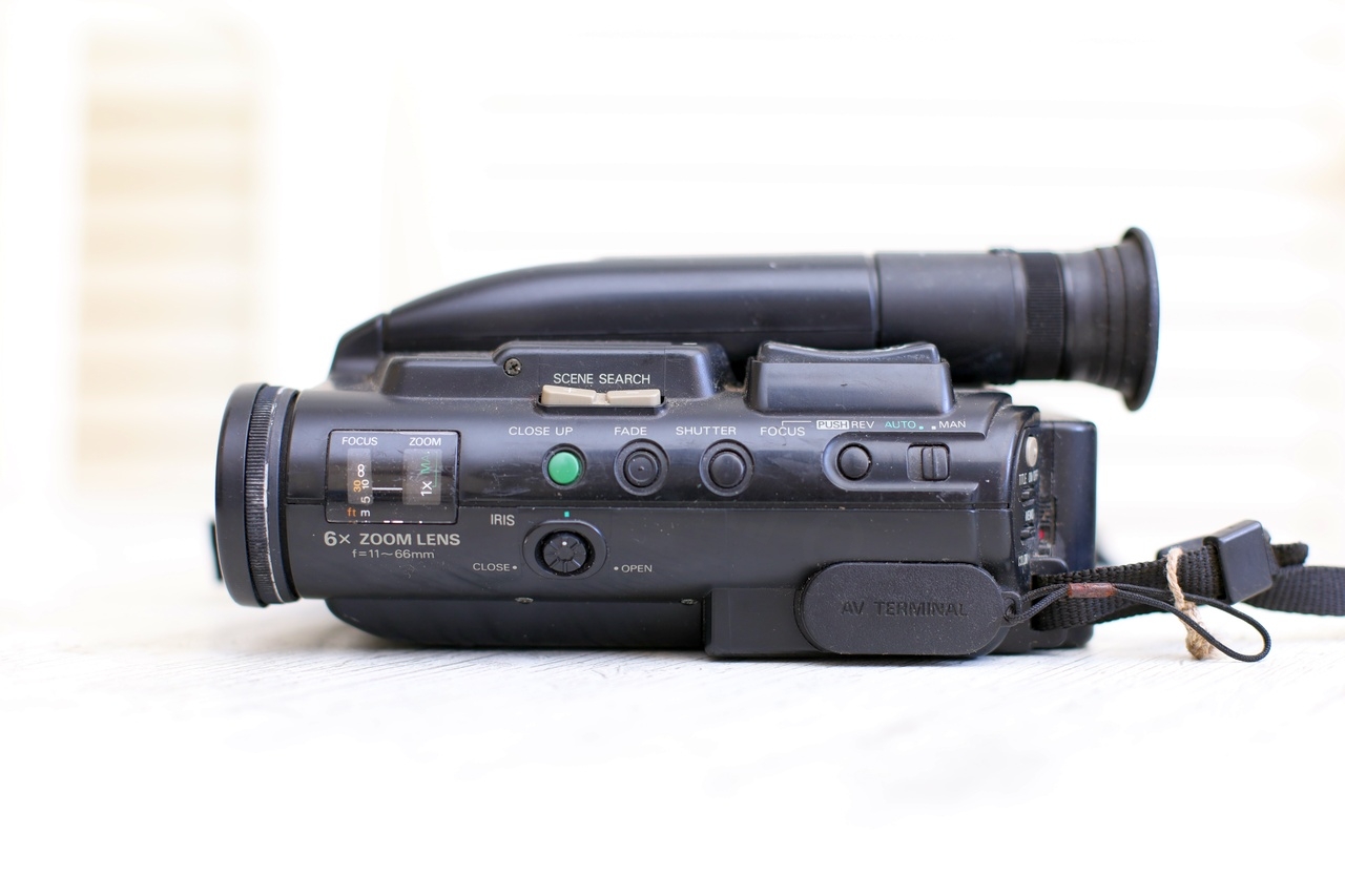
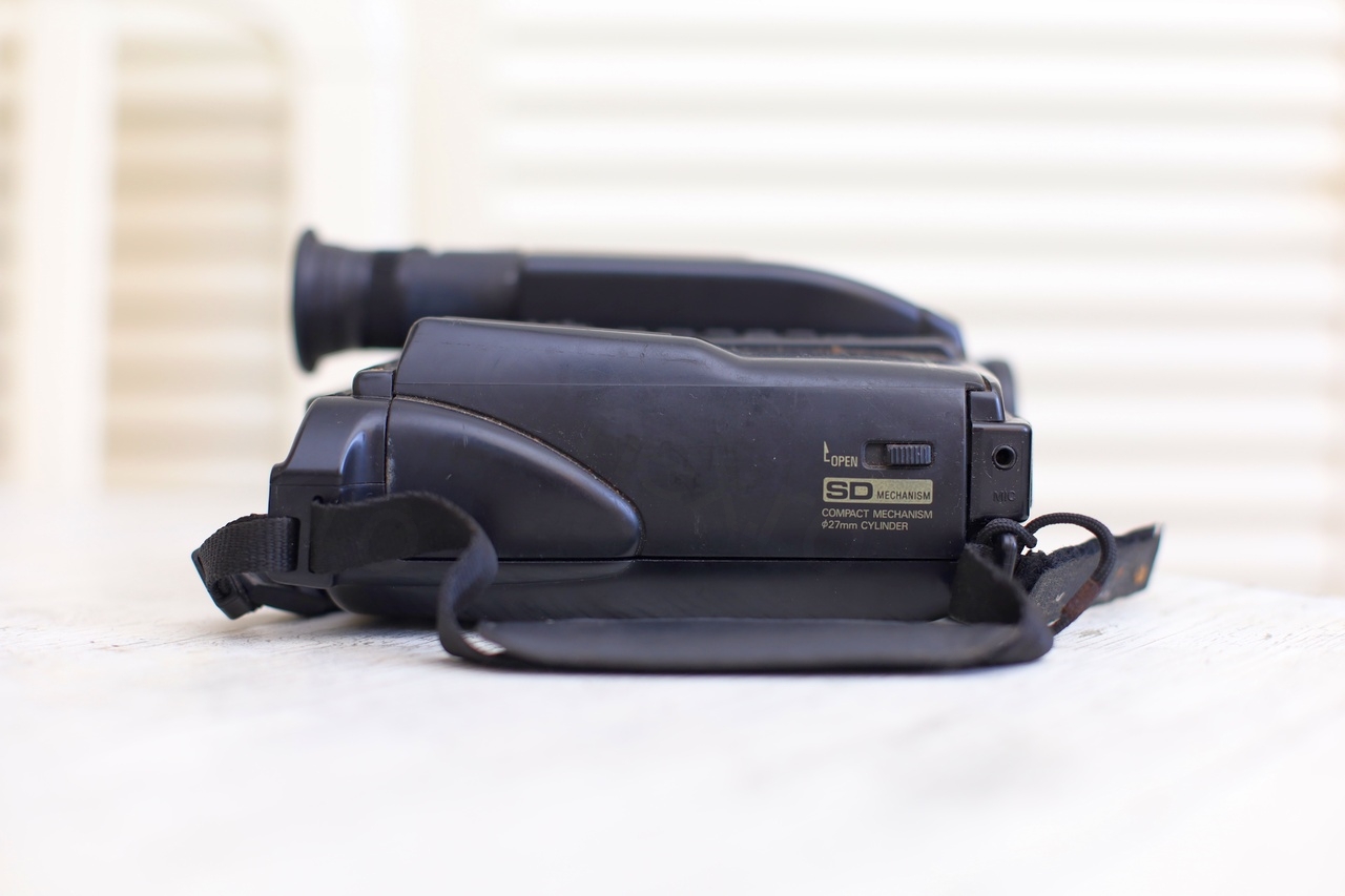
Camera overview
Closeups with the camera:
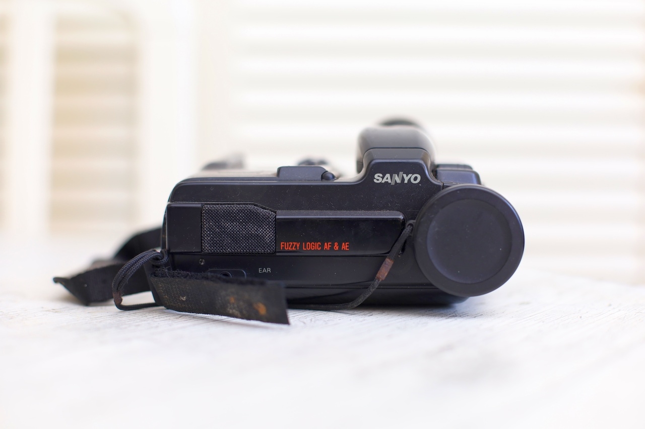
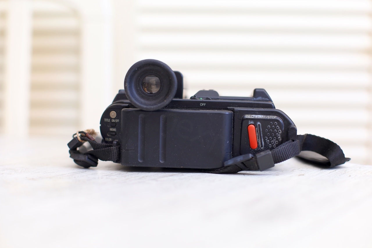
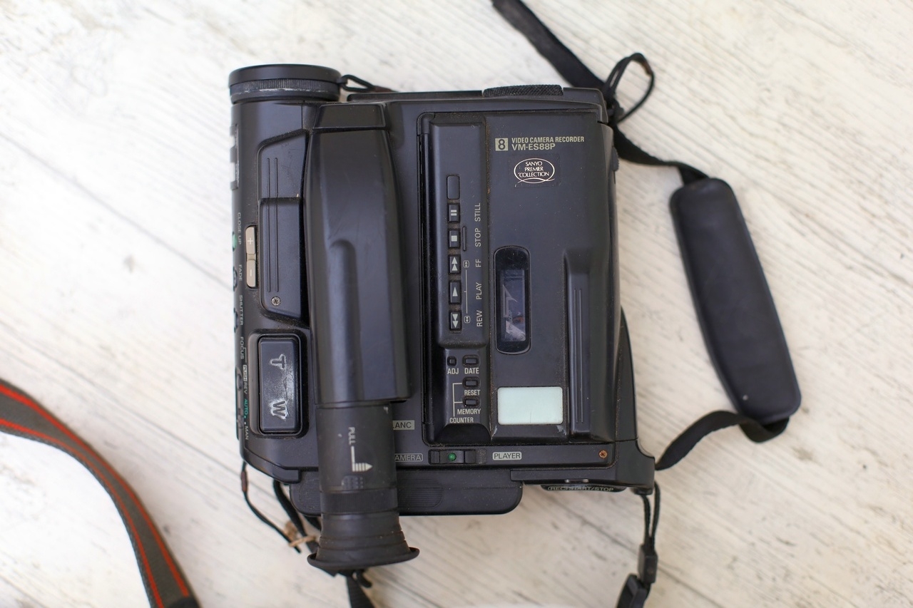
I was surprised to see “FUZZY LOGIC AF & AE” text in red. Big AD words in your face. Was FUZZY LOGIC the early 90s hype ?
What about “AI for AF and AE” – Artificial Intelligence for Auto Focus and Auto Exposure ? No AI with runs on high ESR capacitors though, so let’s have a look.
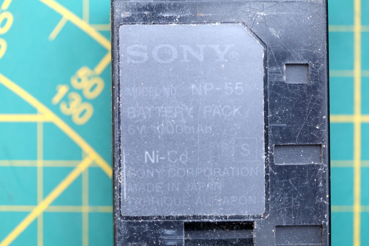
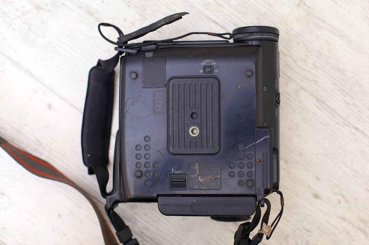
I found it interesting that there was a Sony battery installed. I wonder if this may be an idea for the future ? What if all mobile phones would have the same model of replaceable battery – and you could install same model of battery made by Samsung that would fit any other phone, Motorola, Apple, etc ? Or using a Canon battery in a Sony camera ?
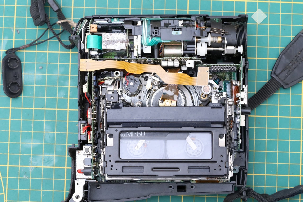
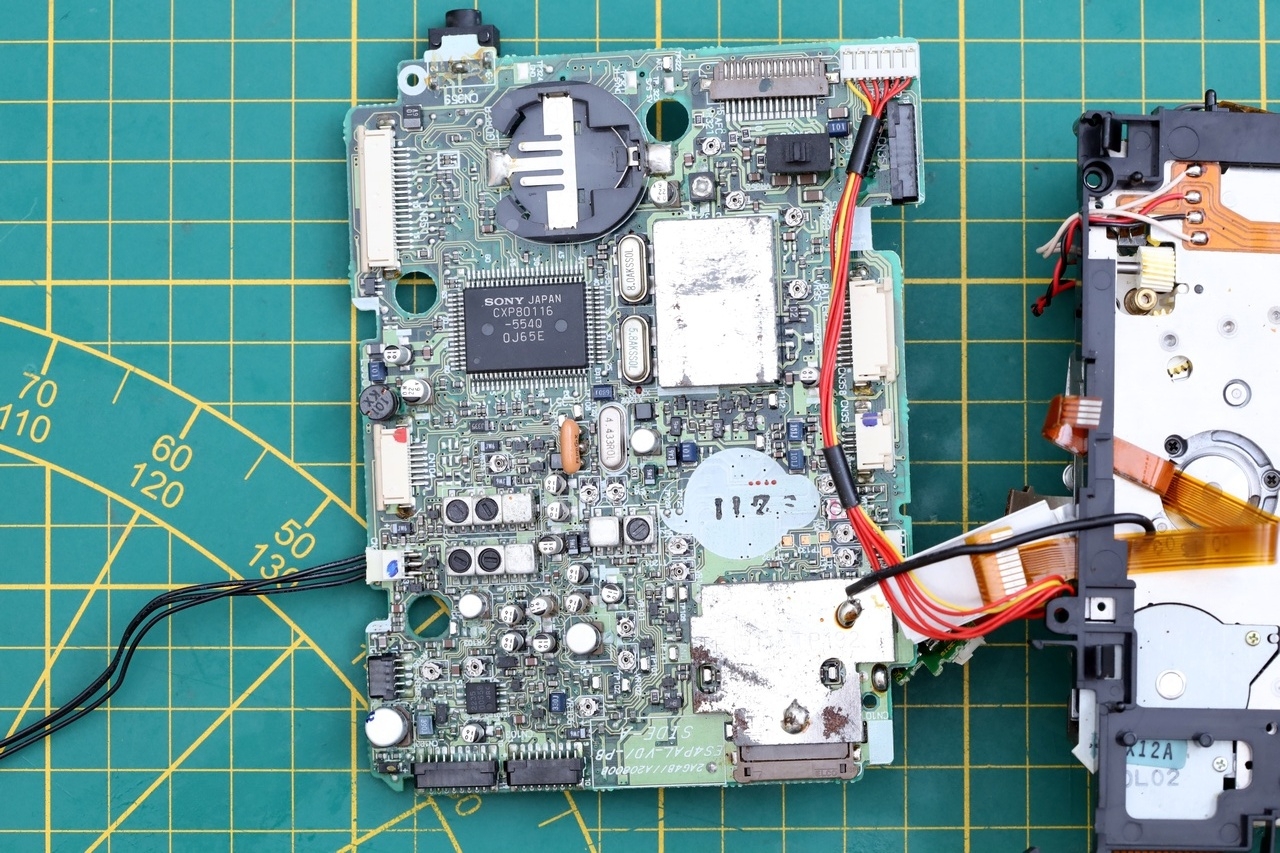
Opening the Sanyo VM-ES88P
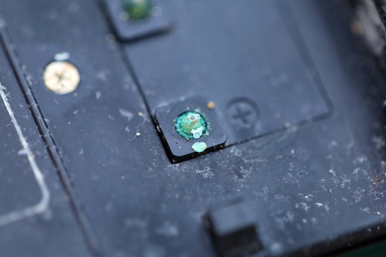
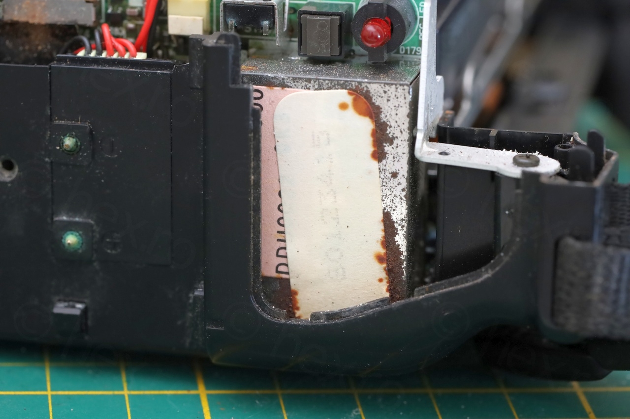
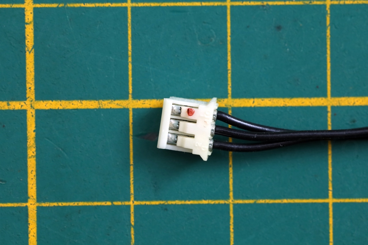
Opening the camera was easy – but I had a hard time taking the captive tape out. I still don’t know what lever to pull to unlock it without power applied. Plenty corrosion inside though, although, the Electronic View Finder seems very easy to control, only 3 signal wires.
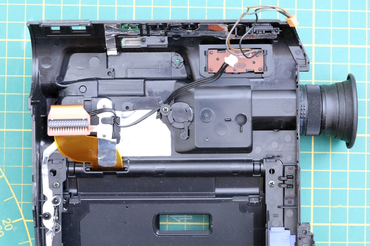
Opening up the EVF Unit
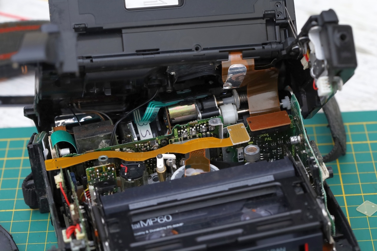
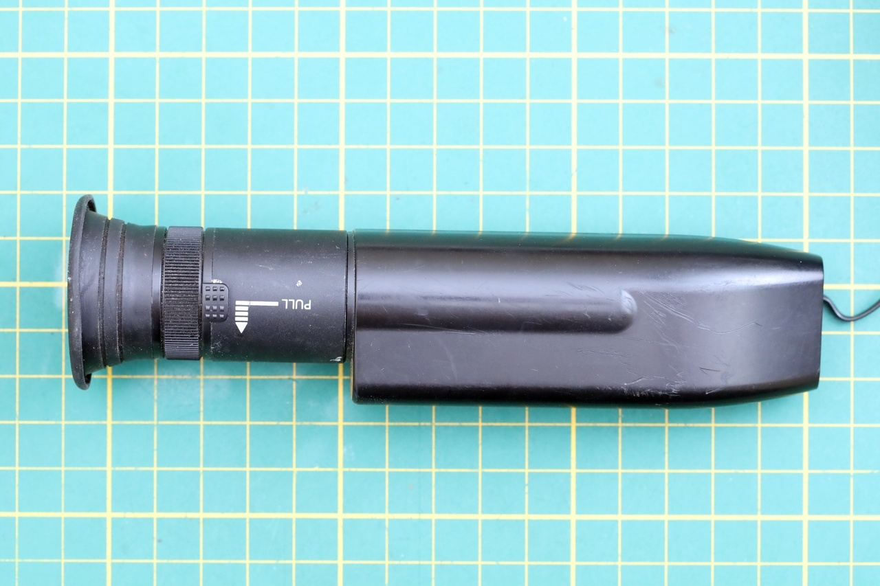
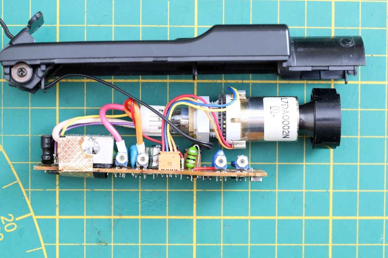
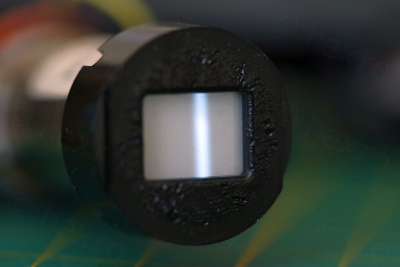
Getting inside the EVF unit was also easy – only two screws holding it together. The plastic was quite stiff though. I was able to pry the two sides apart starting from the smaller cylindrical part housing the CRT itself.
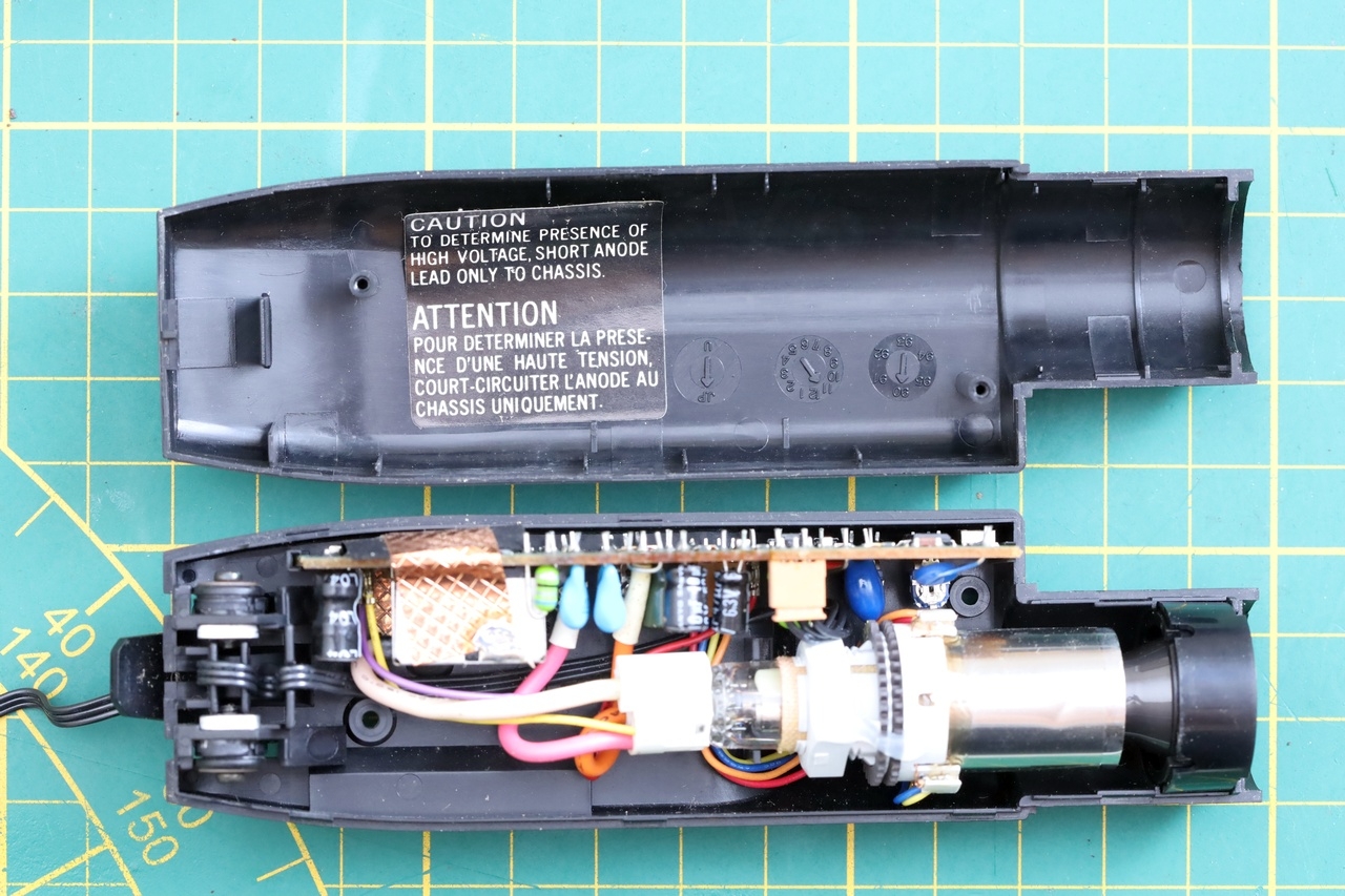
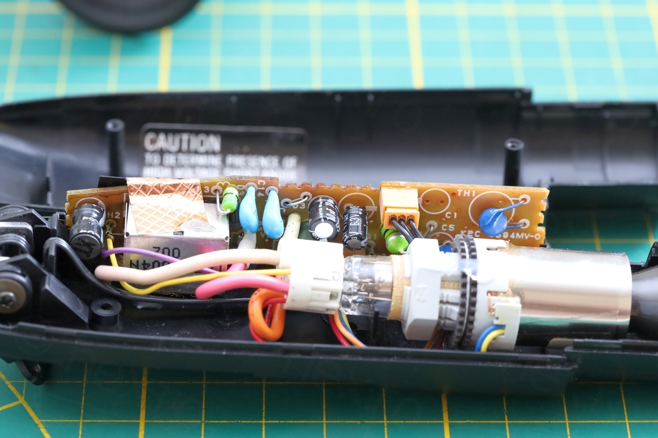
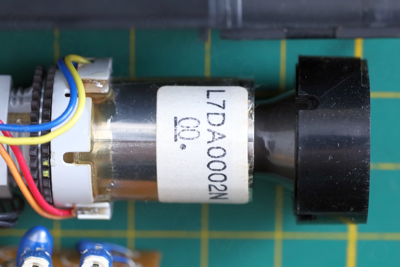
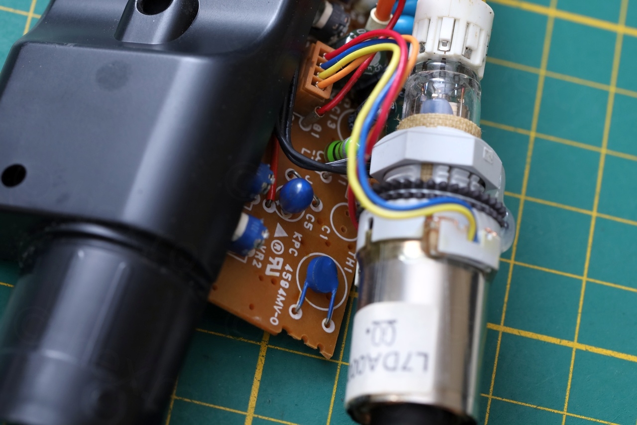
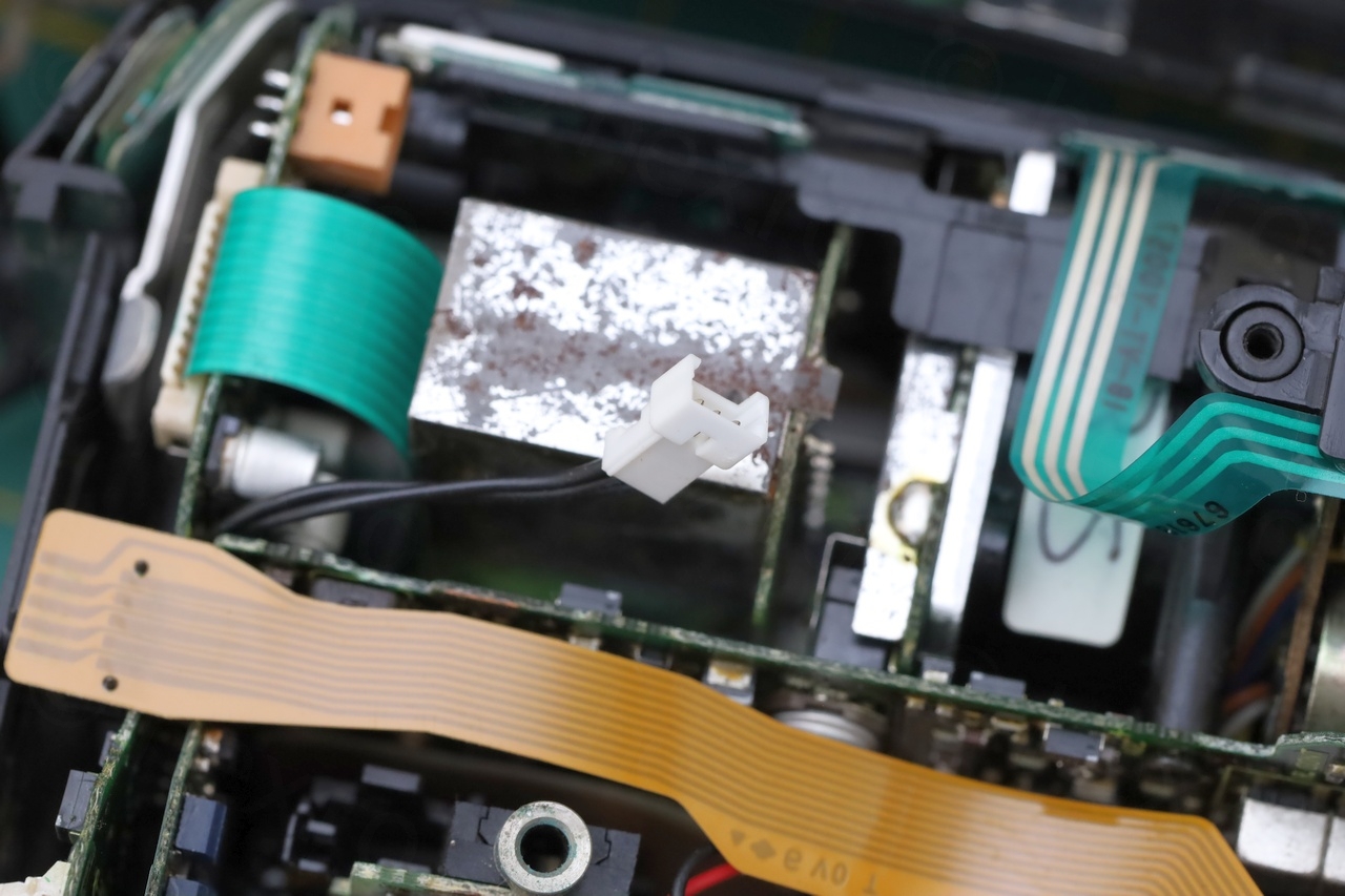
At first view, the Electronic View Finder unit is very clean without signs of leaky capacitors.
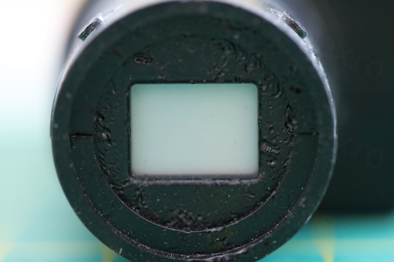
I don’t understand the pitting behind the lens, on the plastic just around the CRT. It is not the first camera I notice this. Was the camera left in the Sun ? Most of the cameras I took apart don’t have this pitting, but few do.
EVF Unit does not power up
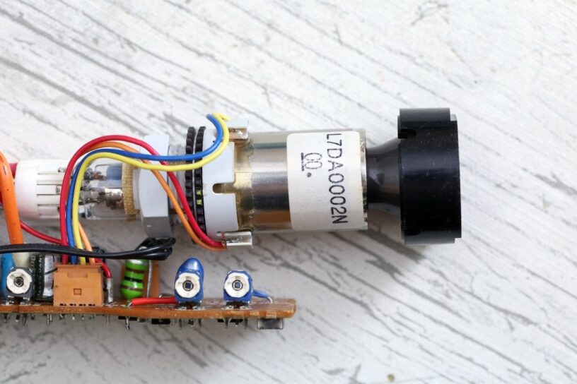
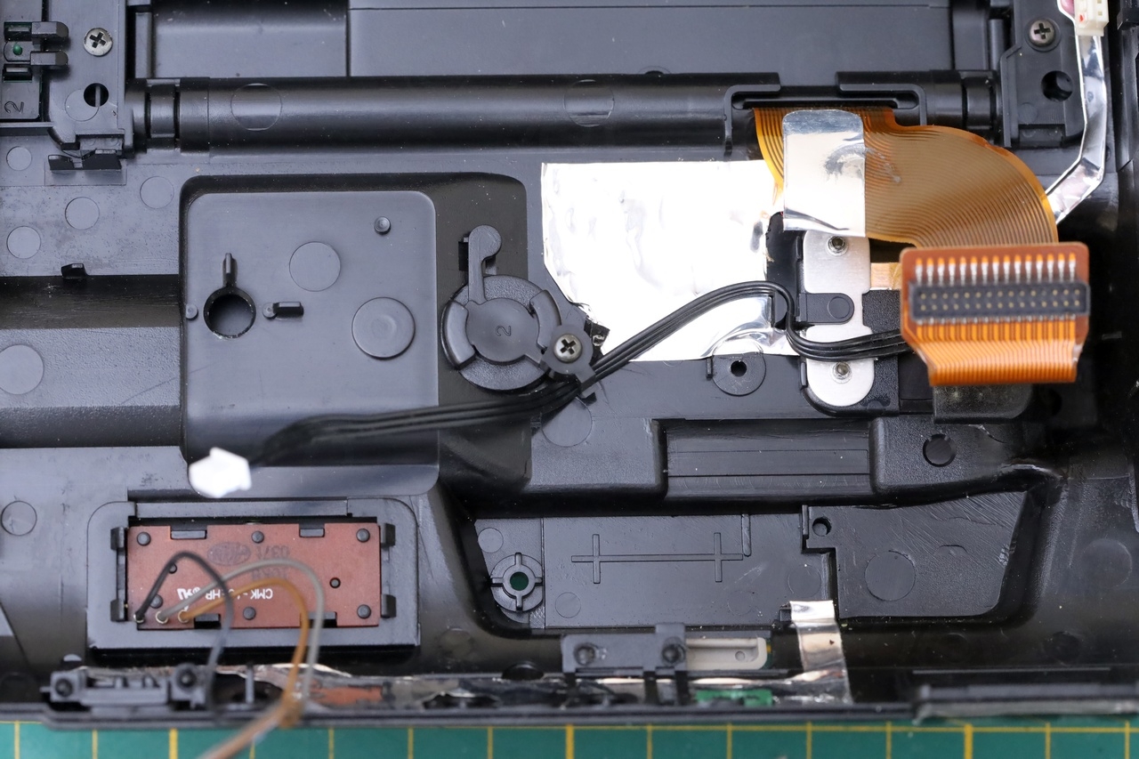
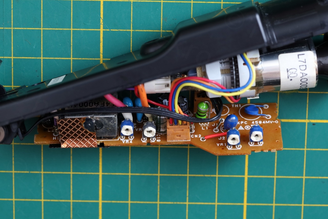
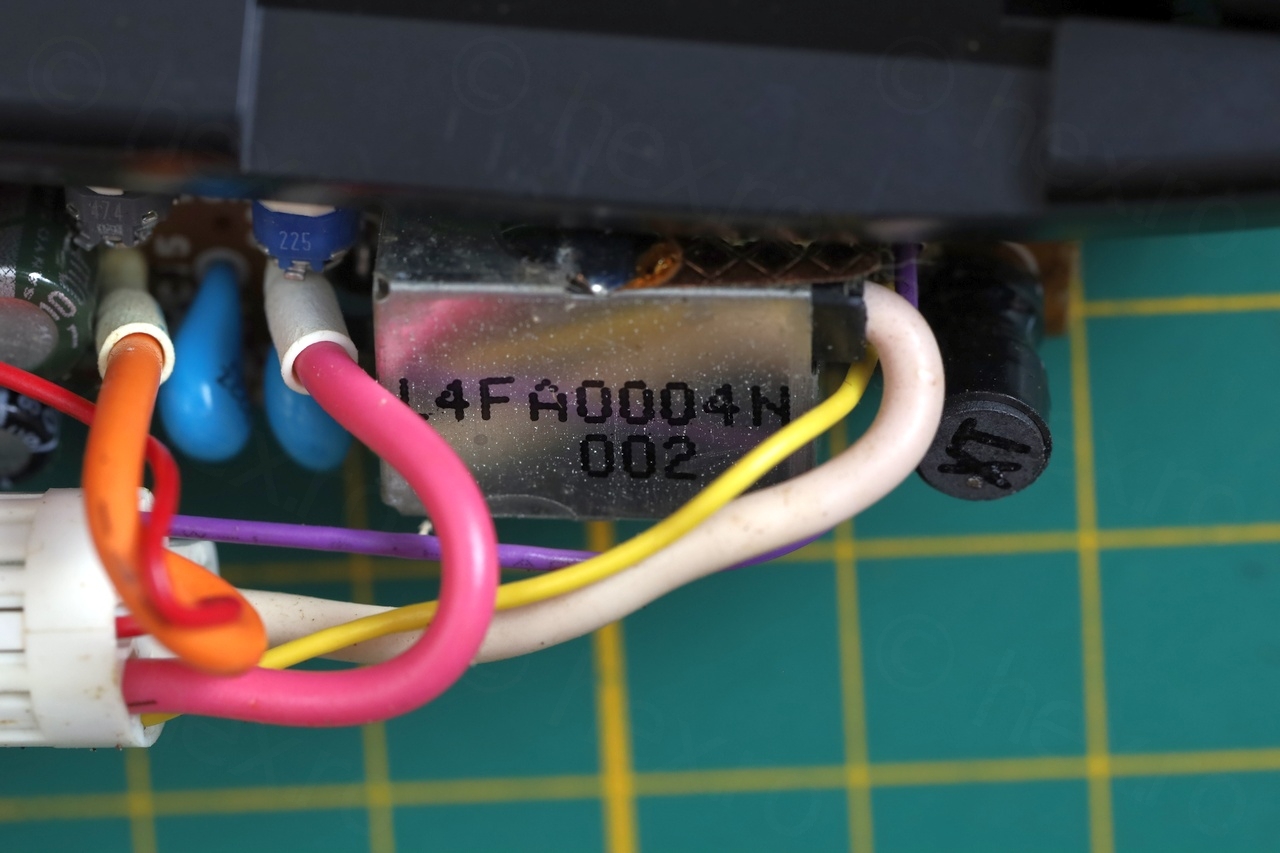
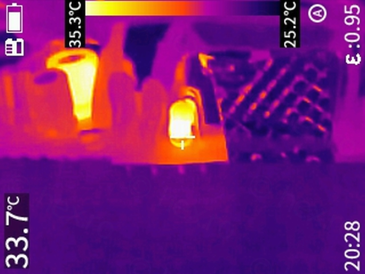
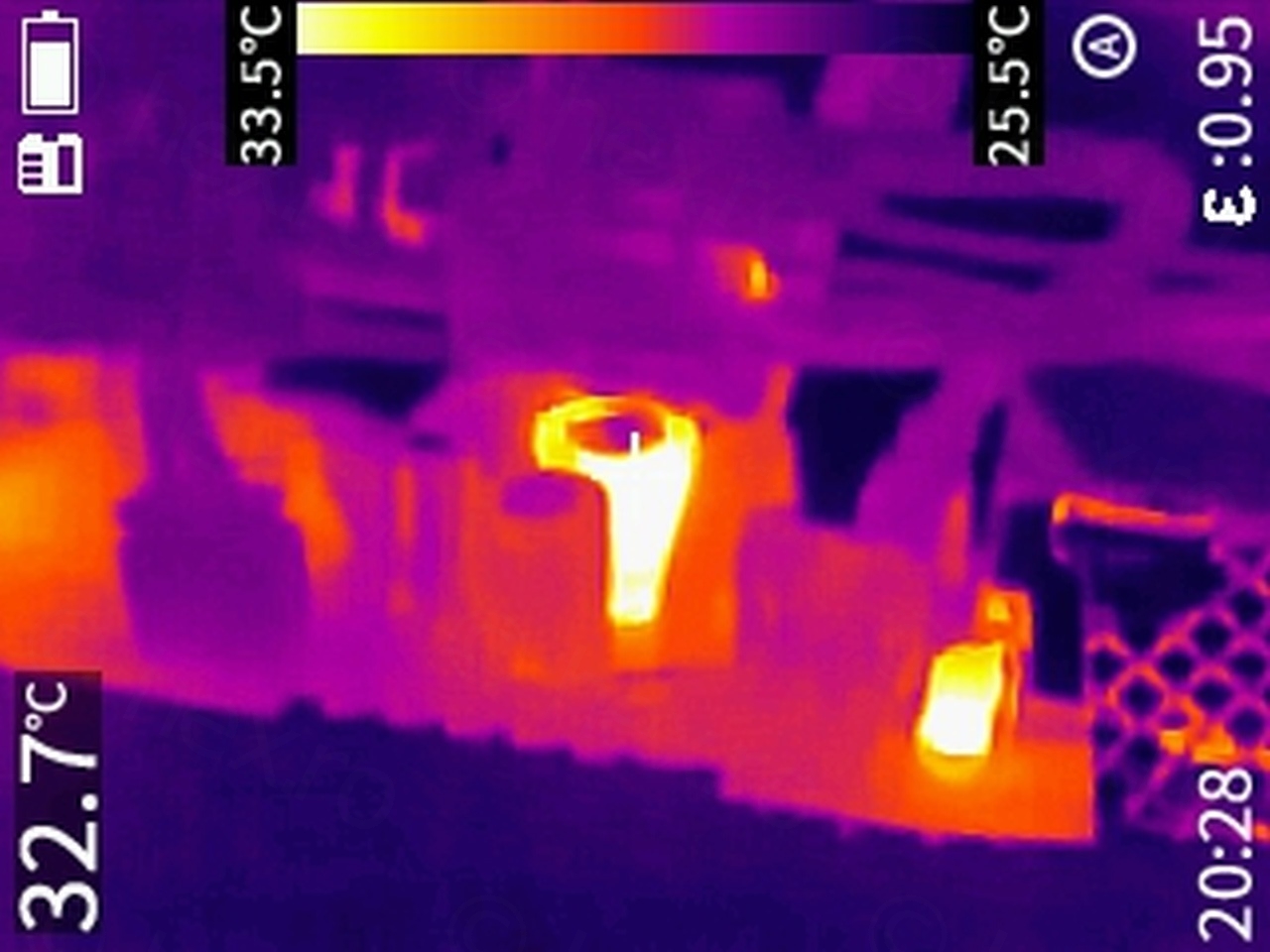
I’ve applied the same technique I always do when trying to figure out which wires are what. Looking to find the Power (VCC), GND and Video IN. GND almost always has continuity to the housing of the Flyback Transformer. Due to capacitors charging, sometimes VCC shortly beeps. Some of the FBT pins are also connected to VCC, but here I didn’t want to take apart the shielding.
Thinking this is a straightforward job, I decided to power it up with 5V and surprise. No High Voltage wine and no image on the CRT.
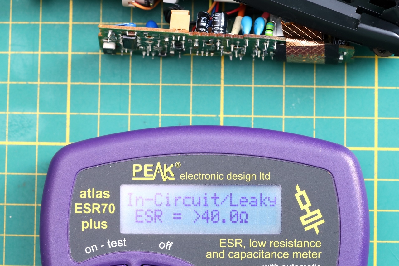
What was very weird was that the power draw was constant – 130mA.
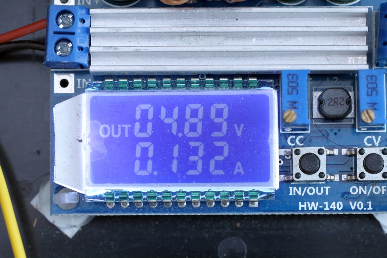
Not only that it was constant – is also higher than what a normal EVF of this type to draw. When fully working, they draw around 100mA. So is something getting hot ?
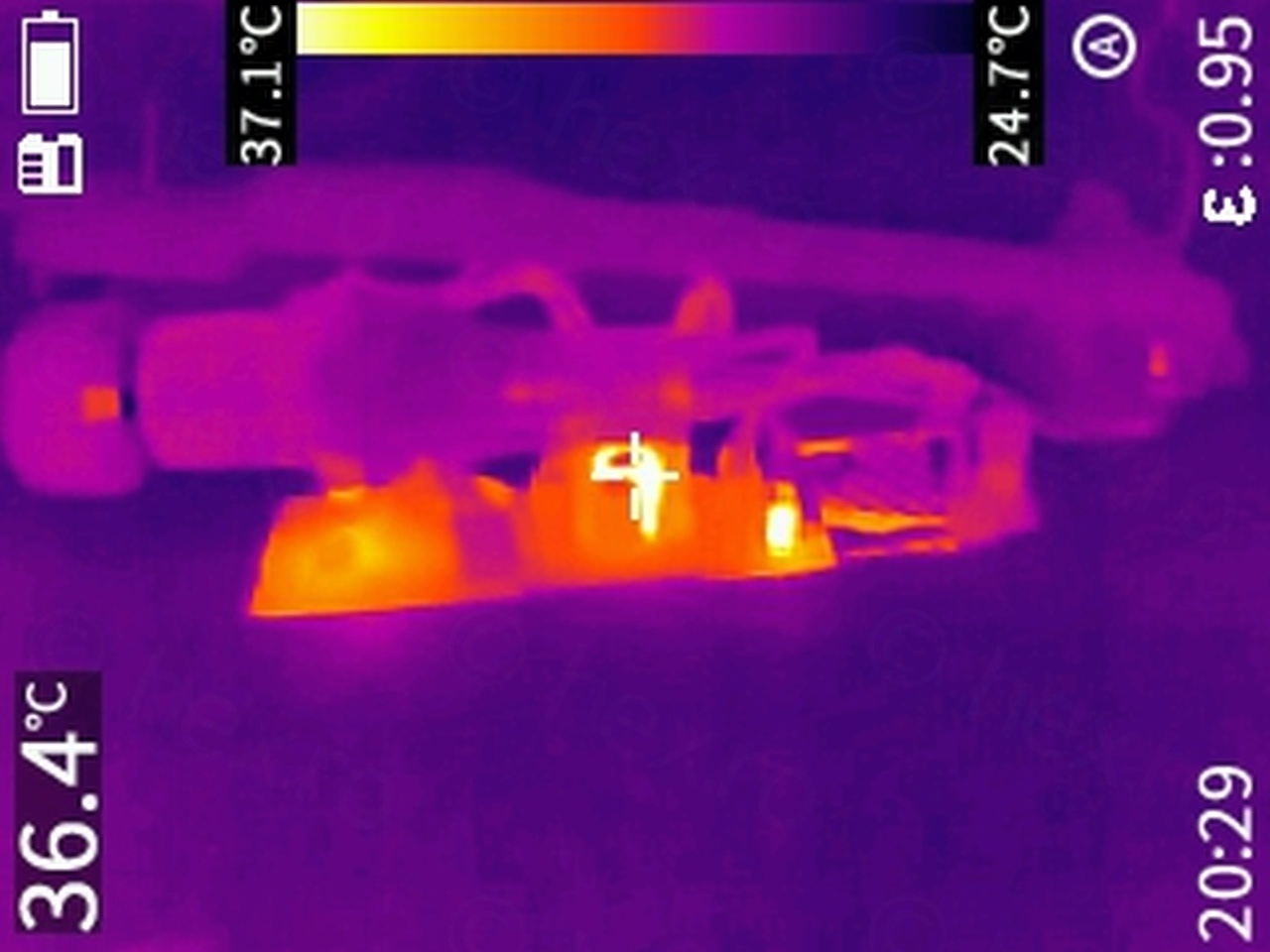
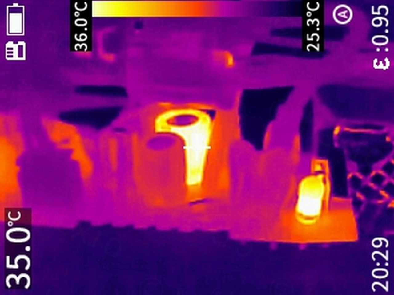
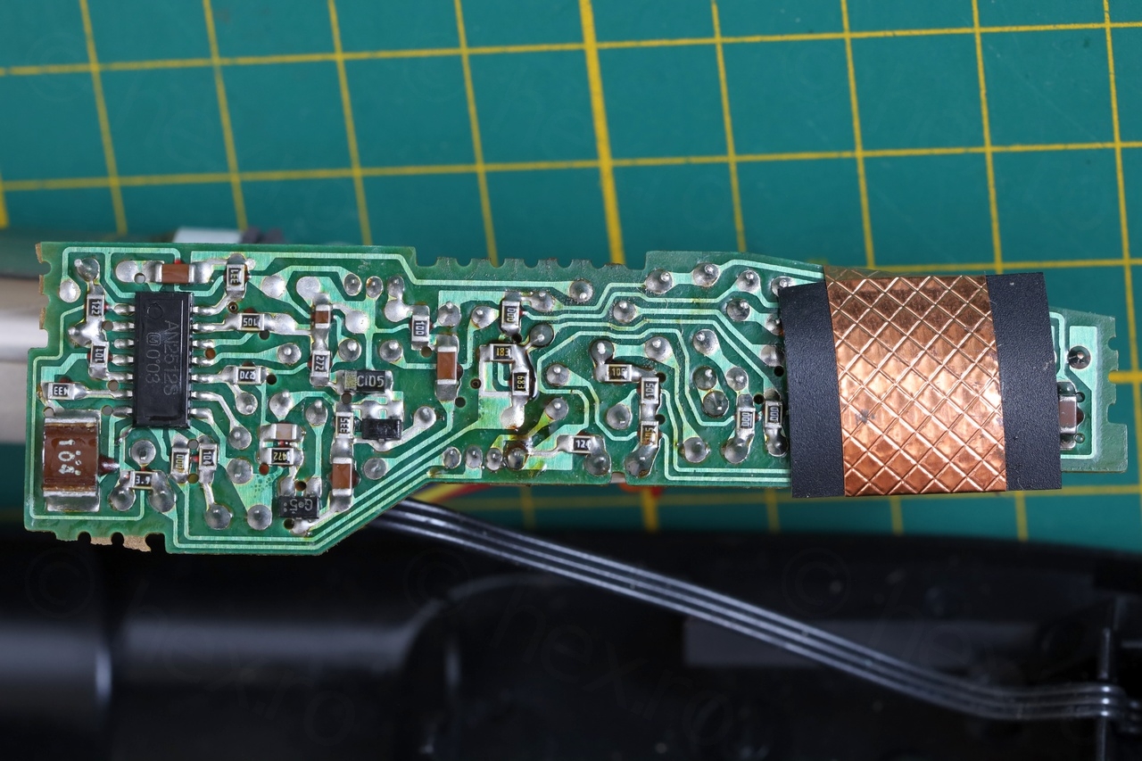
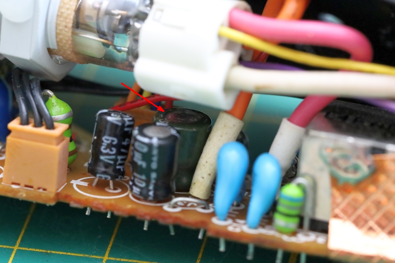
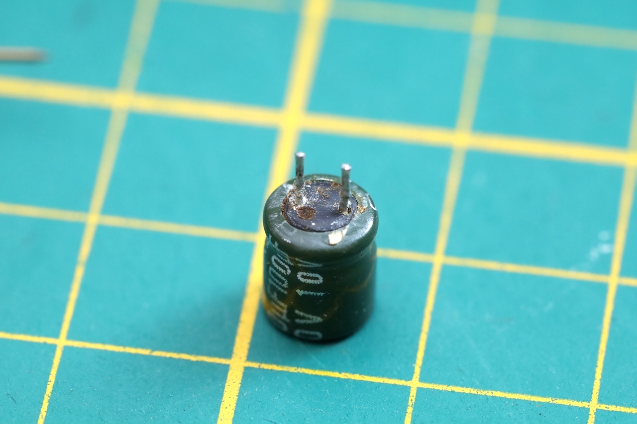
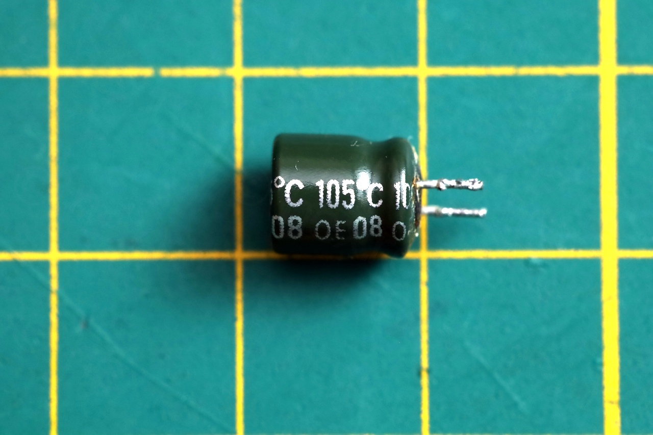
So one of the capacitors is actually drawing all the power. I proceeded to extract it:
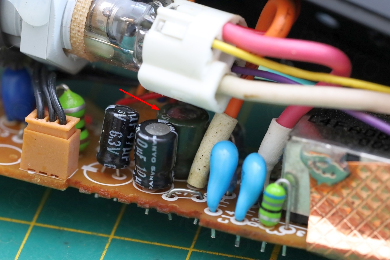
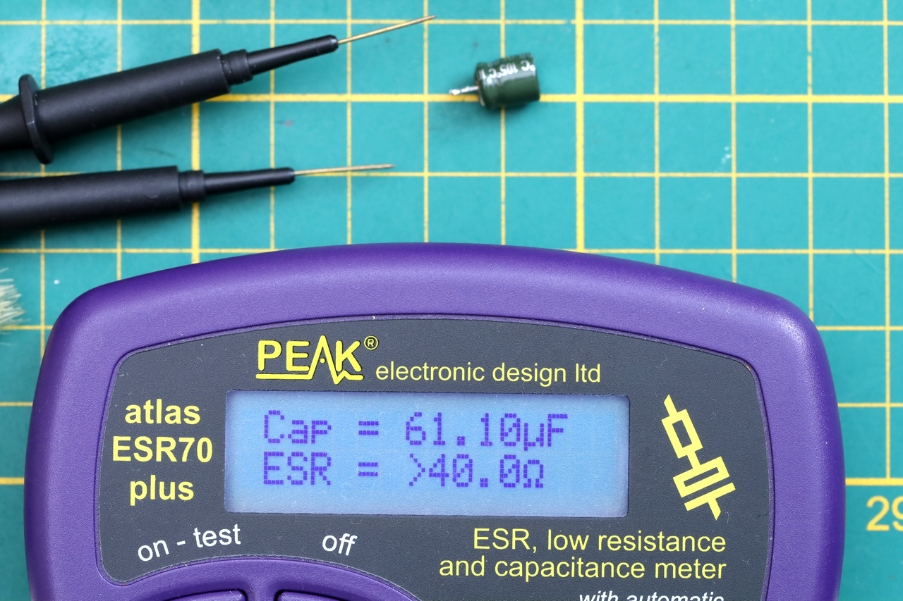
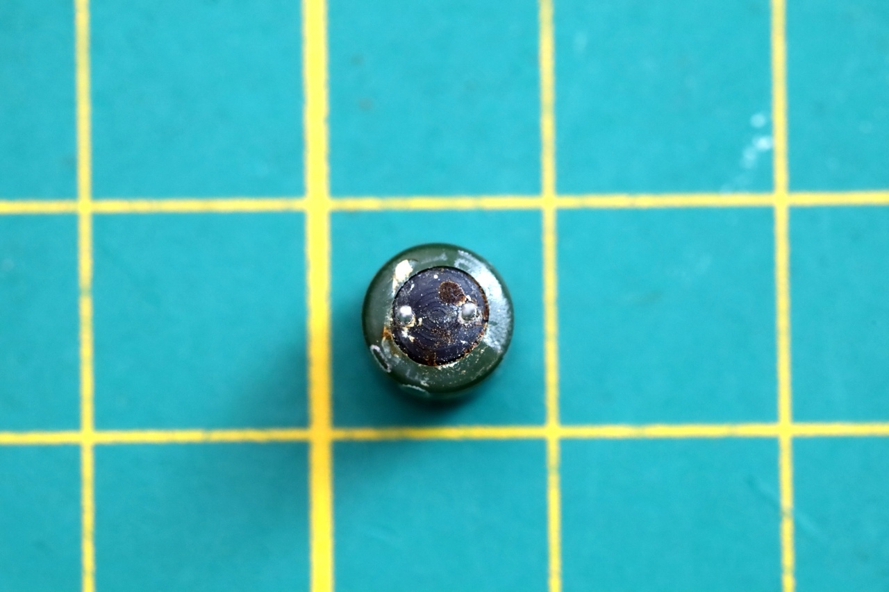
Curiosity got the best of me and decided to power on the board without it, just to see what gives. Results:
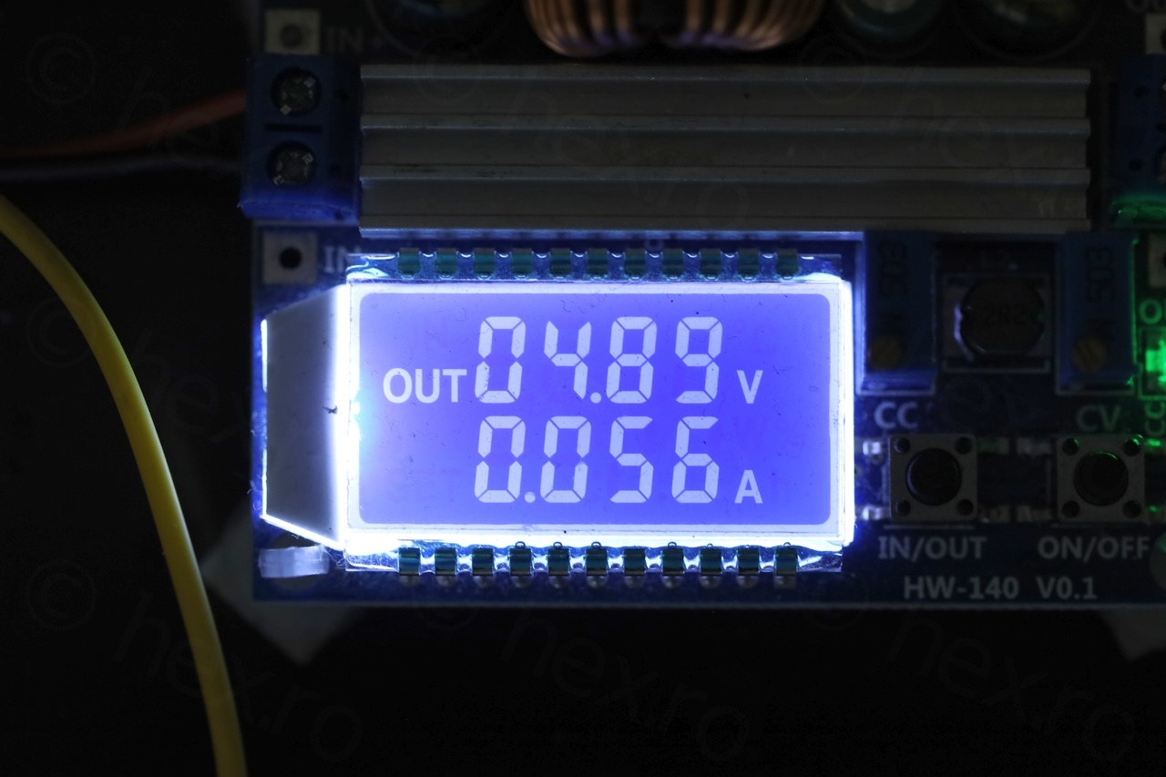
- Power draw dropped to 52mA
- CRT turned on…
- … but was displaying a vertical (fat) line.
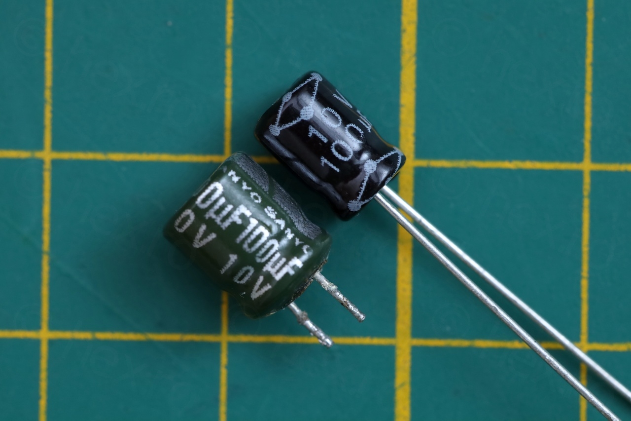
Replacing the capacitor fixed the board.
Testing
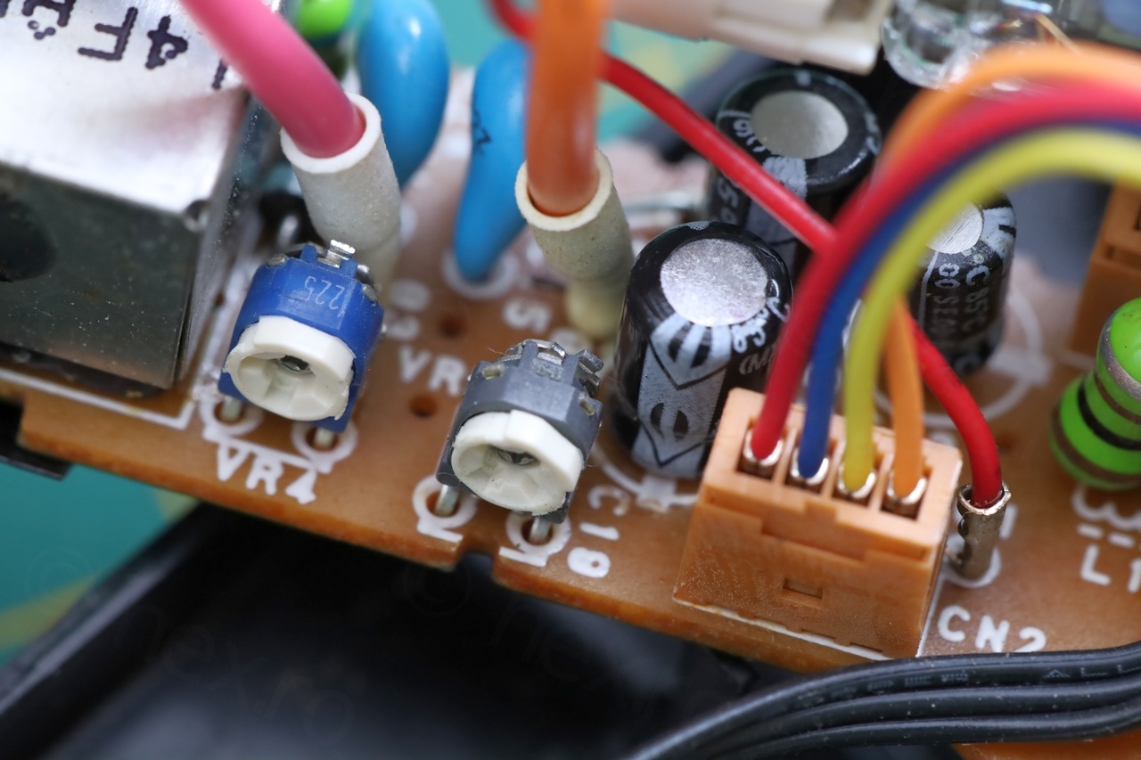
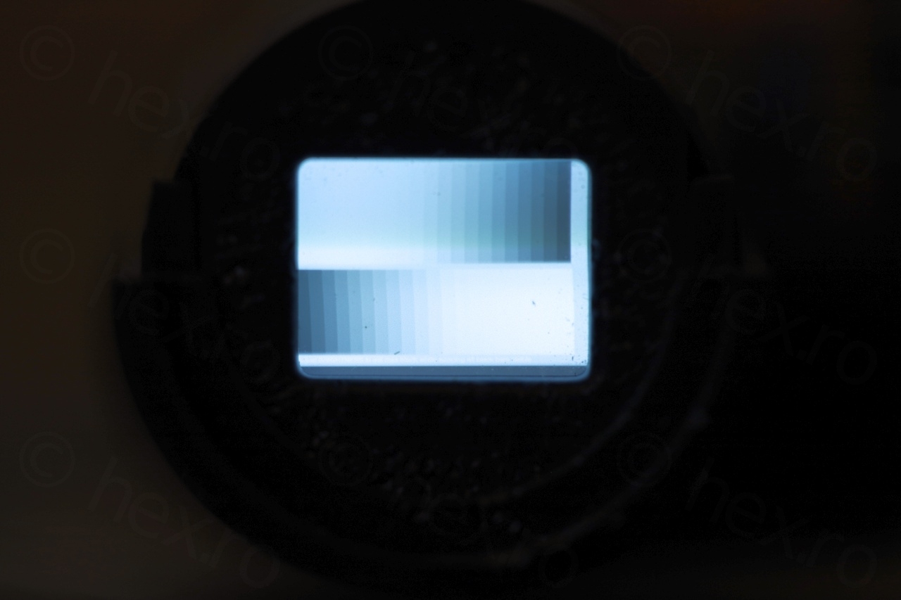
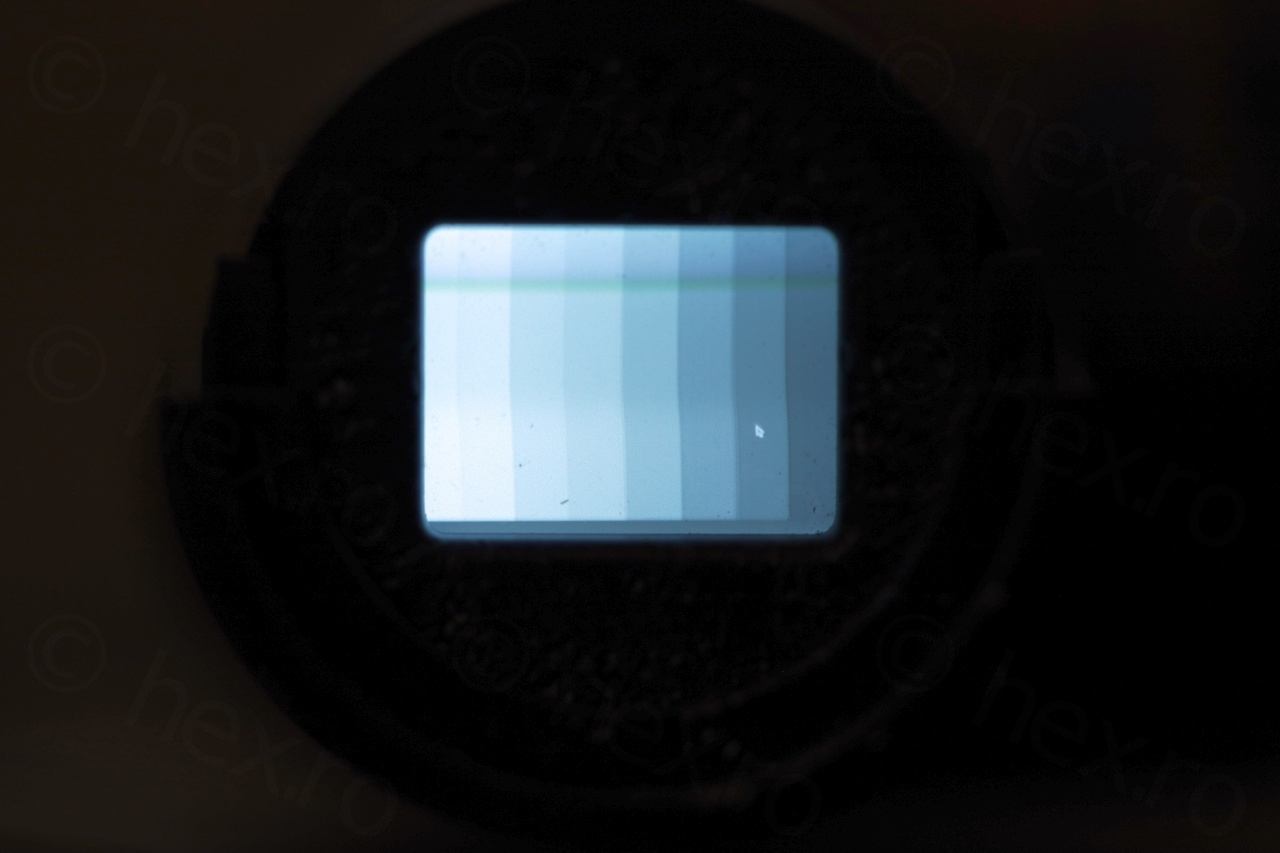
The CRT works nicely and has good contrast as you will see below. I did not try to calibrate or touch the potentiometers. For the sharpest image – I had to bump the voltage to 5.4V, where it draws 100mA:
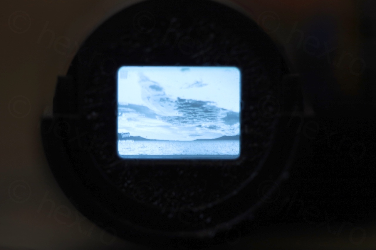


The EVF unit was nice to work with and ample room to service it. One more added to the collection …
SA4HMR
Hej,
you have a nice time on your screen.
How do you realise it, please?
Thank you very much.
Sincerly
Harry.
viulian
Hello,
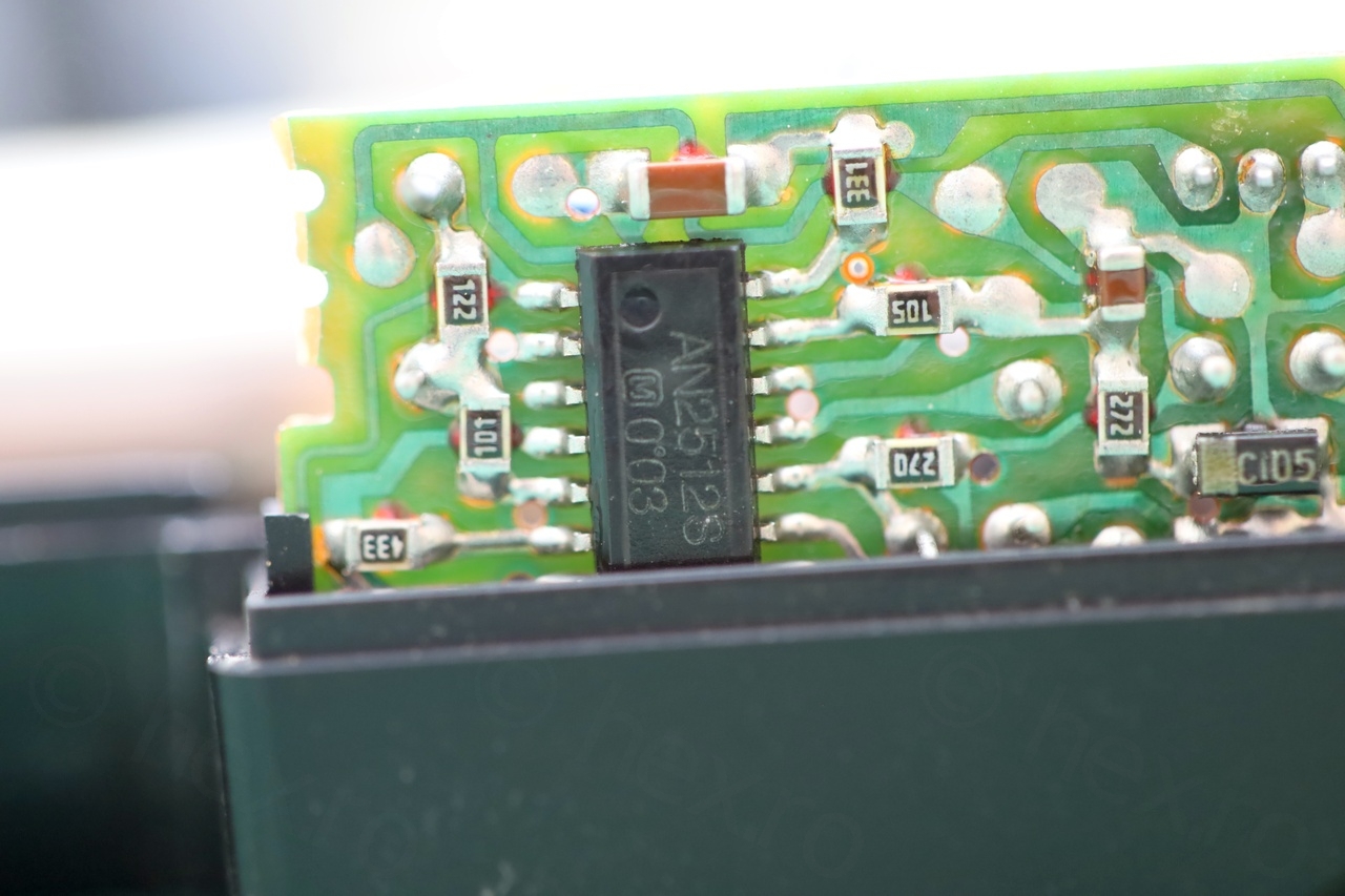
These driver boards come already with an IC that is able to convert a normal Composite Video signal (originally, from the inside of the camera) into an image on the CRT.
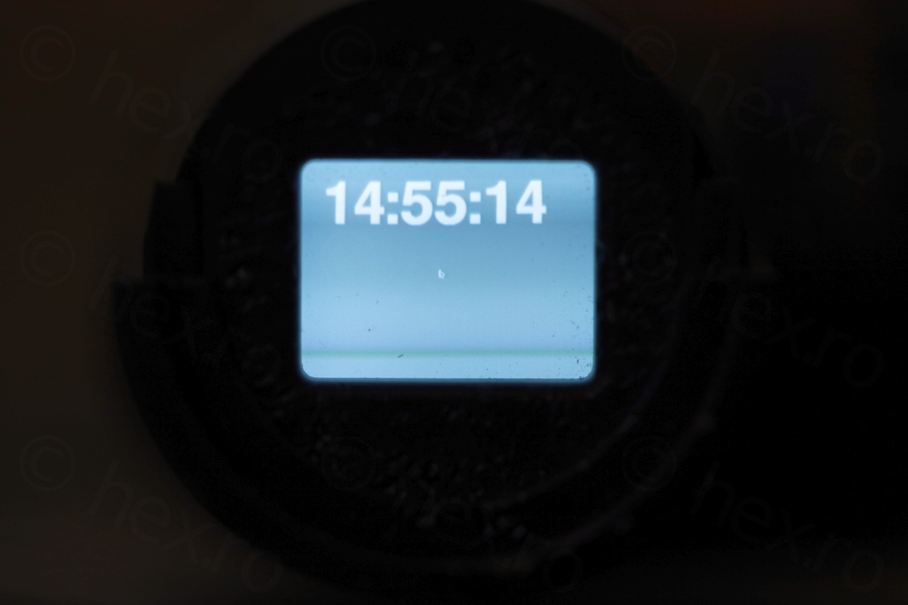
I use a Raspberry PI in Composite Video output mode (instead of HDMI). So everything PI outputs appears on the CRT.
In particular, the time is just a Python script (using a very large font) to print the time in Full Screen mode.
About controlling the CRT directly (to use it more like an oscilloscope), that is too complex for me. The high voltages of the Fly Back Transformer are a deterrent :). I guess it can be done, reusing the FBT, to control the X and Y directly (instead of relying on the driver IC to do it). But I never went that route.
Tyg
hello I’ve got one these video camera recorder and don’t know how to open the cassette part and I’m wondering if you could help
viulian
I can’t help, sorry 🙁 … I too had problems opening it up (most likely since I don’t remember, but I probably had to break things apart to salvage the cassette).
Tehan
the pitting on the plastic around the crt is caused by the sunlight magnifying through the lense infront of the crt,according to my knowledge.