


This is my take on building a Ceramic Cartridge Phono Pre-Amp using a unity gain buffer (or a unity gain amplifier).
Table of Contents
- Introduction
- Picking up a schematic
- Power and noise considerations
- Prototyping and PCB layout
- Bill of materials
- Circuit board
- Case
- THD Measurements
- TL082ACP vs OPA2134PA
- Caveats
- References
Introduction
Ceramic Cartridges are modeled as a voltage source in series with a Capacitor. When the cartridge is connected to the amplifier, it creates a RC high-pass filter where the R (R1 in the schematic below) represents the input impedance of the amplifier:
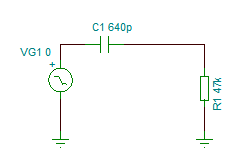
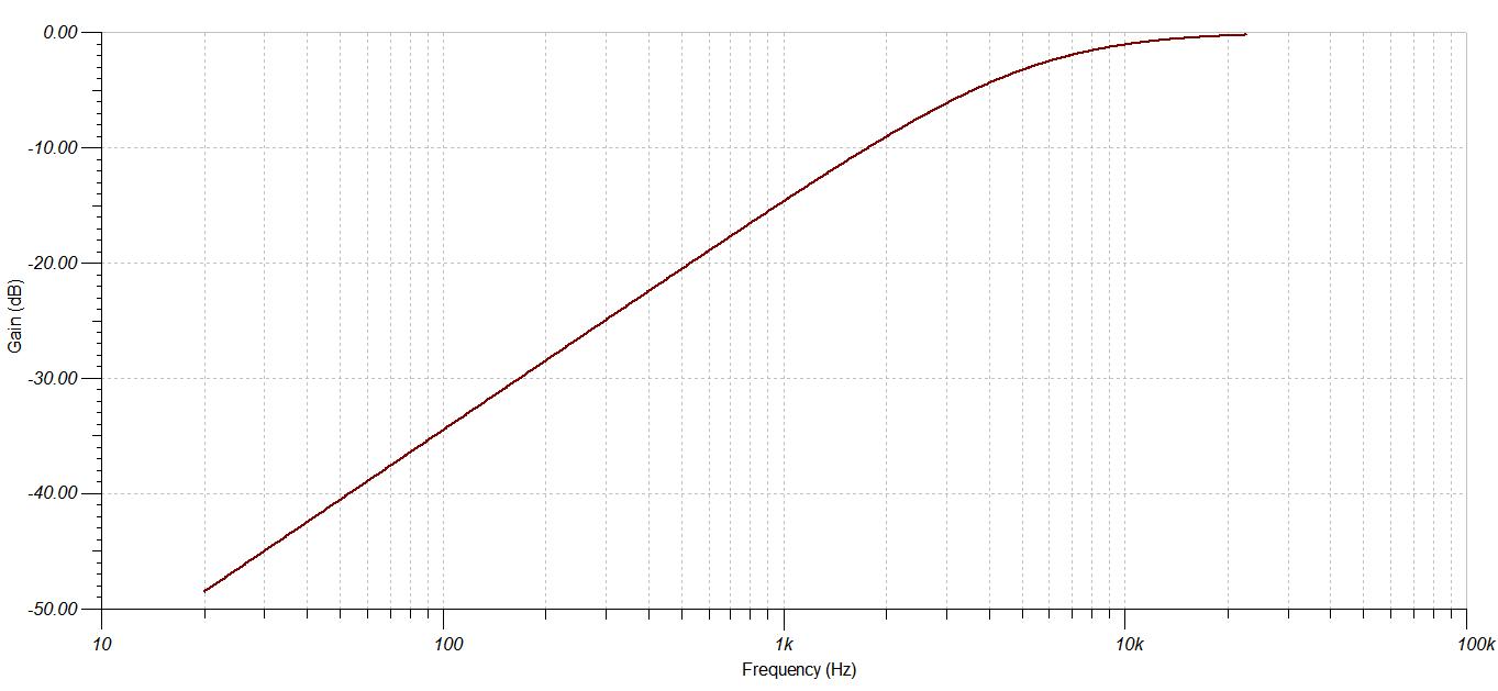
The 3db cut-off frequency of a high pass filter is equal to 1/(2πRC). For a C of 650pF (which is what I measured for the BSR SC5H) and R = 47kΩ, the cut off frequency is 5.2KHz – thus, when connecting a ceramic cartridge turntable directly to a modern amplifier, the bass + mid frequencies will be heavily attenuated:
The signal produced by the cartridges would be enough to drive modern amplifier if there would be a small device presenting high impedance to the cartridge and just carrying the same amplitude signal to the amplifier. Enter a “unity gain” buffer.
Picking up a schematic
Looking for a suitable unity buffer, I stumbled onto “Preamp Stage For Ceramic Phono Cartridge Or Violin Pickups” schematic. It is posted on few websites and I was able to track it down to the June 2002 Silicon Chip magazine. It is using a 10MΩ input bias resistor and a TL071 FET input opamp for a single (mono) channel.
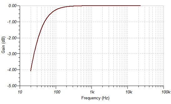
A simulation in Tina TI to check for the AC Transfer Characteristic …
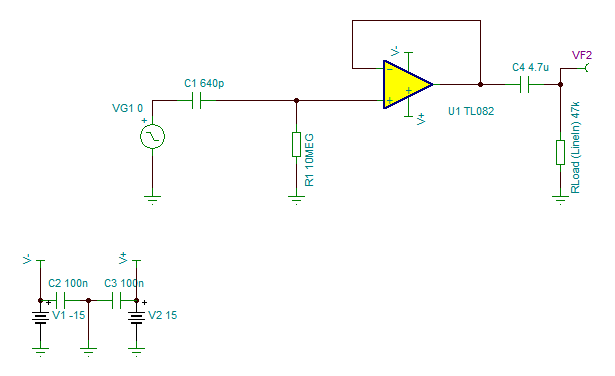
… produces very promising results, where the -3db point sits at 25Hz:
PS: Initial schematic calls for TL071 but I went with TL082ACP which has two opamps that I would use for stereo.
Power and noise considerations
Before assembly, some other details had to be ironed out, for example, how to power on the opamp or how to reduce possible noise picked up from the environment ?
First, the power: I needed a through-hole DC to DC converter that could take a 5V input and provide the -15V and +15V while able to source at least 1mA of current that the TL082 needs. I chose TBA 1-0523HI which is a little overkill (providing 33mA for each of the – / + sides).
Second, the noise:
- full metal case to reduce noise pickup from the environment
- surface mounted high value resistors (10MΩ each) since shorter leads means less noise pickup
- thin shielded coax cable that brings the signal from the RCA input plugs down to the board
Prototyping and PCB layout
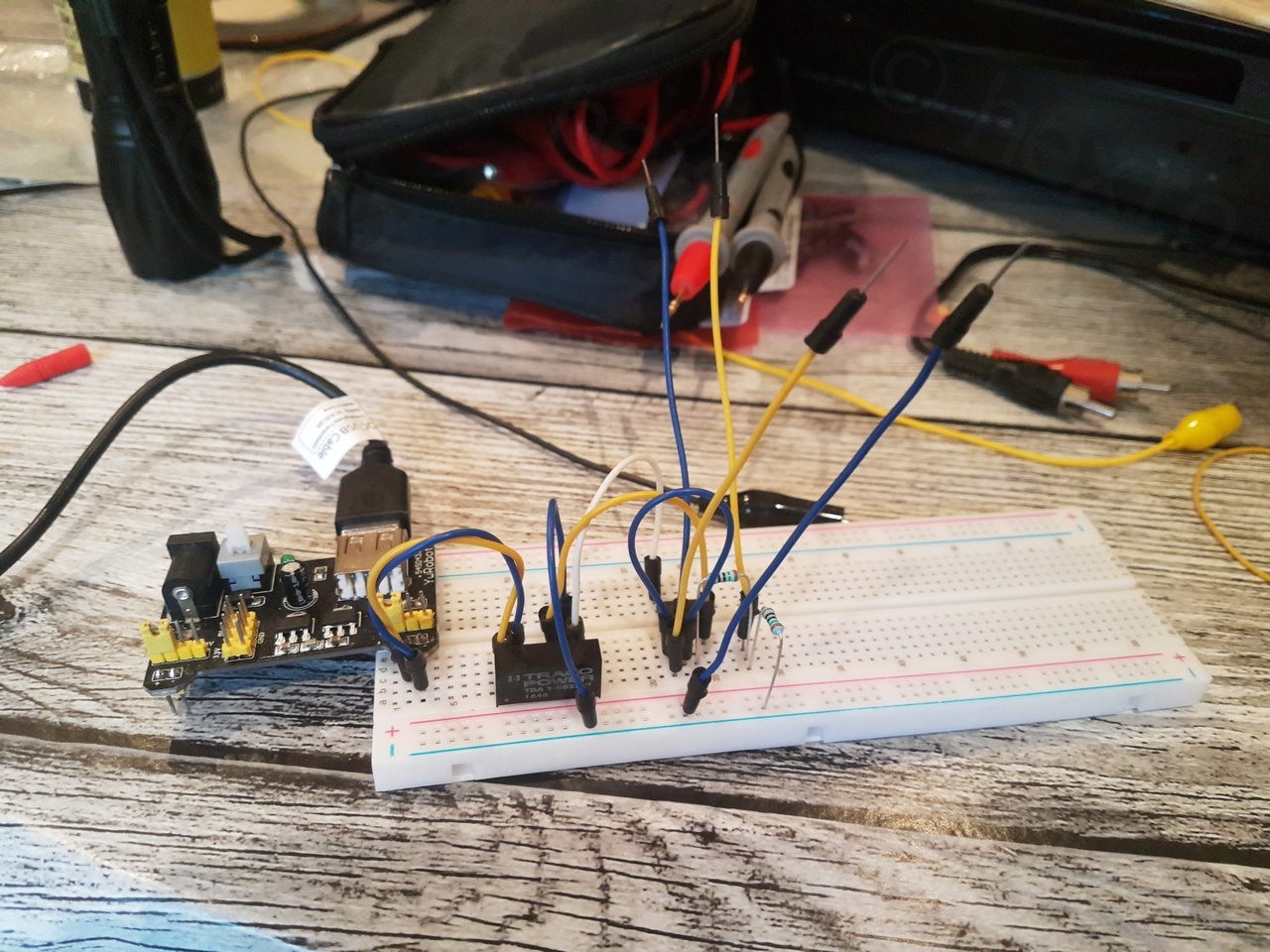
Prototyping proved that the circuit works so I could now focus on preparing the enclosure and soldering the components on the circuit board:
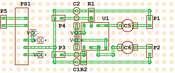
I wasn’t sure that the circuit would fit on a 3cm x 7cm double sided prototyping board. To clarify my thoughts on the layout found a very useful software called VeeCAD. Conclusion is that the parts would fit, layout was fine and had a goto reference to help when mounting the components to the board:
Bill of materials
The following materials were used:
- Output capacitors: 4.7µF @ 50V ceramic capacitors from Murata, reference RDEC71H475K2M1H03A (chosen for their small size) – 2 needed.
- Power: Traco Power DC to DC converter, 5V to -15/+15, reference: TBA 1-0523HI
- Power decoupling capacitors: Ceramic Disc Capacitors, Multicomp Pro, 0.1 µF, 50 V, reference: MCFYU6104Z6 (2x)
- Power plug: Pro Signal PSG01769
- USB to 5.5×2.1 plug 1m cable
- Coax cable: Multicomp Pro RGMini, reference: PP000843
- Case: Aluminum box 100x50x25mm, reference: RTM5002/12-BLK
- RCA Plugs: PSG08299 and PSG08301 (2x of each, Red and White)
- Header pin sockets
- Texas Instruments TL082ACP FET input op-amp (1x)
- Stand-offs so that the bottom of the board does not rest against the metallic case. I used some glasses screws + silicone caps that I had around.
- Wires
For the power, I have so many USB chargers around that I figured reusing one would be the best. Thus, 5V input, a standard panel mount 5.5×2.1mm socket and a cable from USB to 5.5×2.1mm jack to solve the problem.
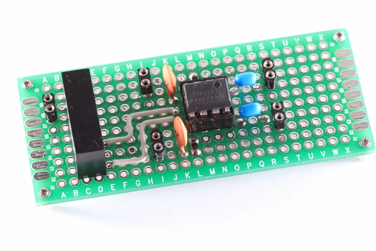
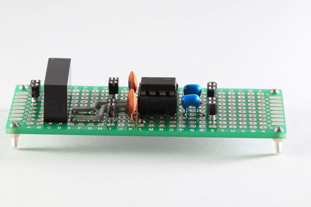
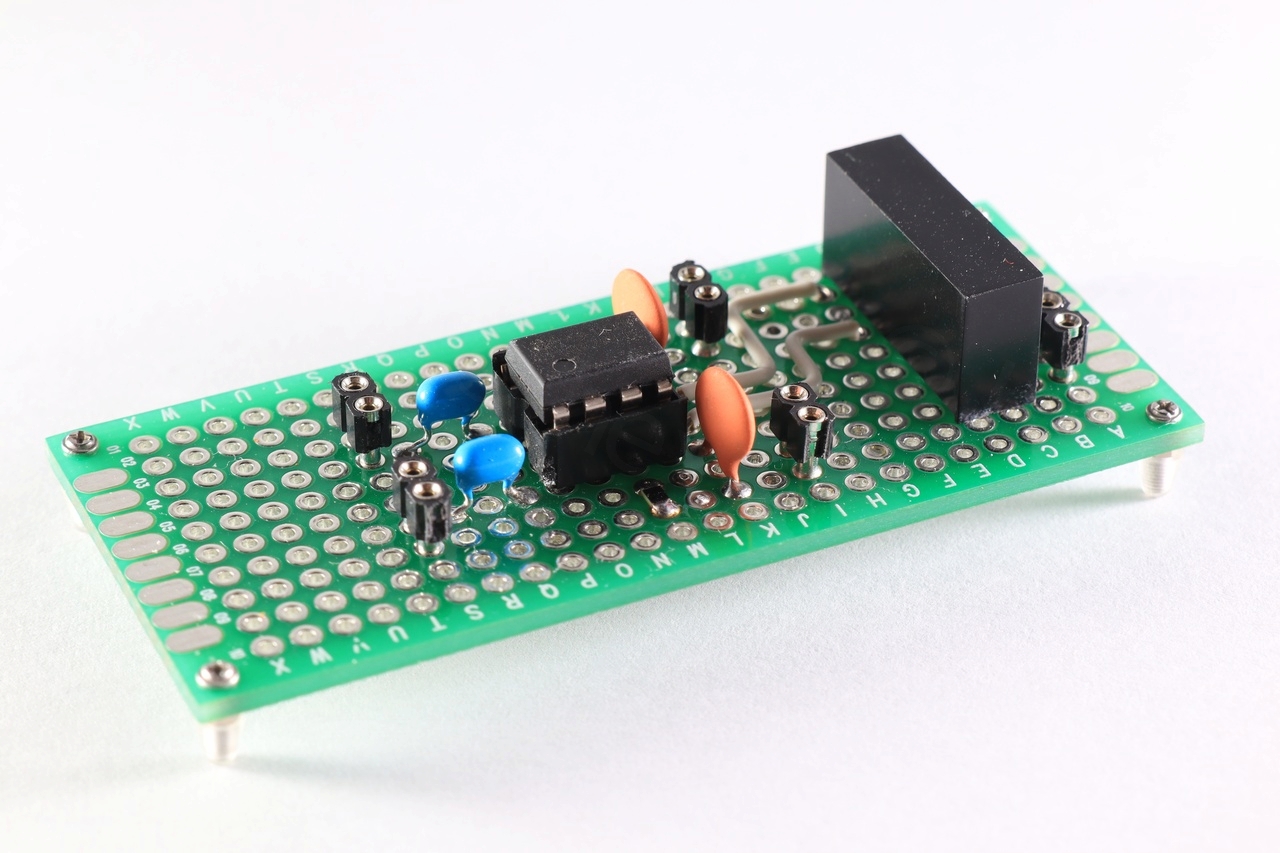
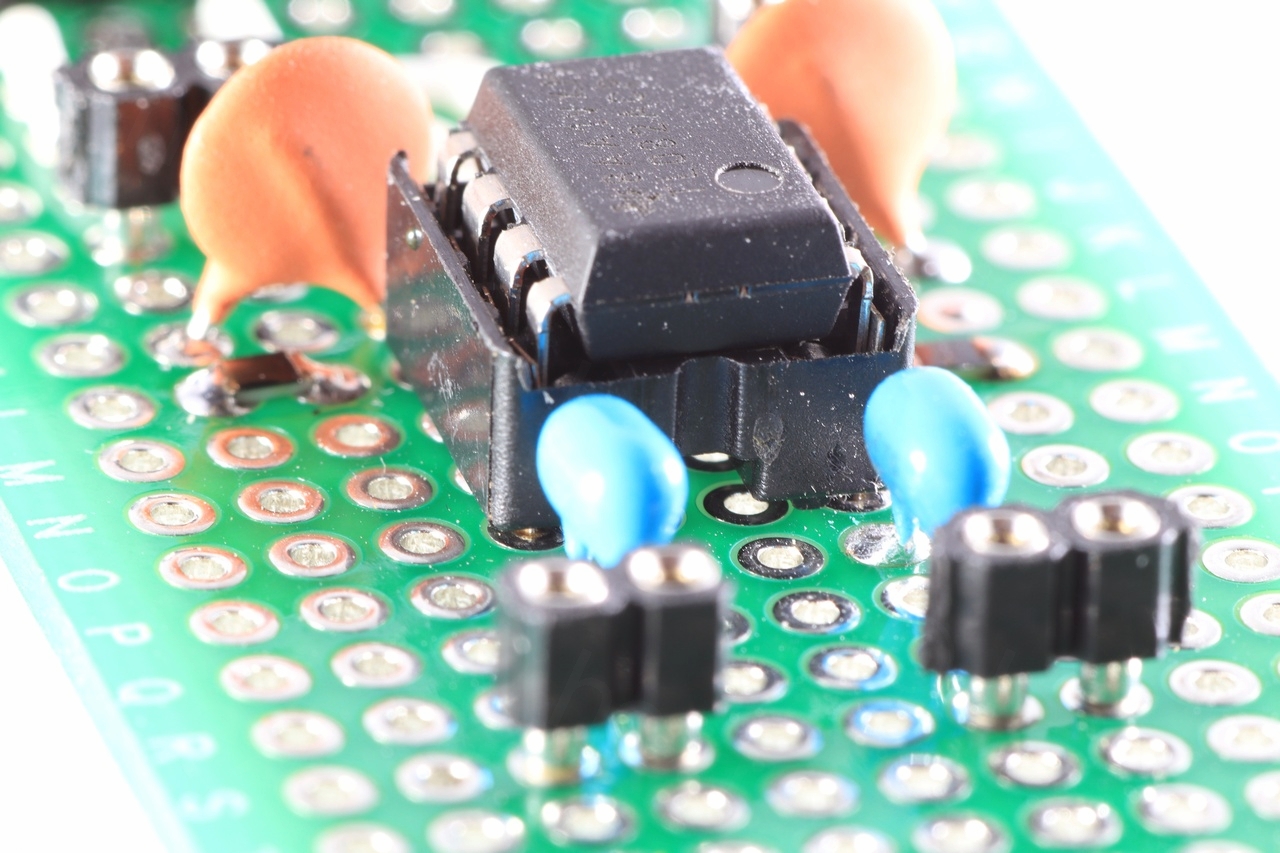
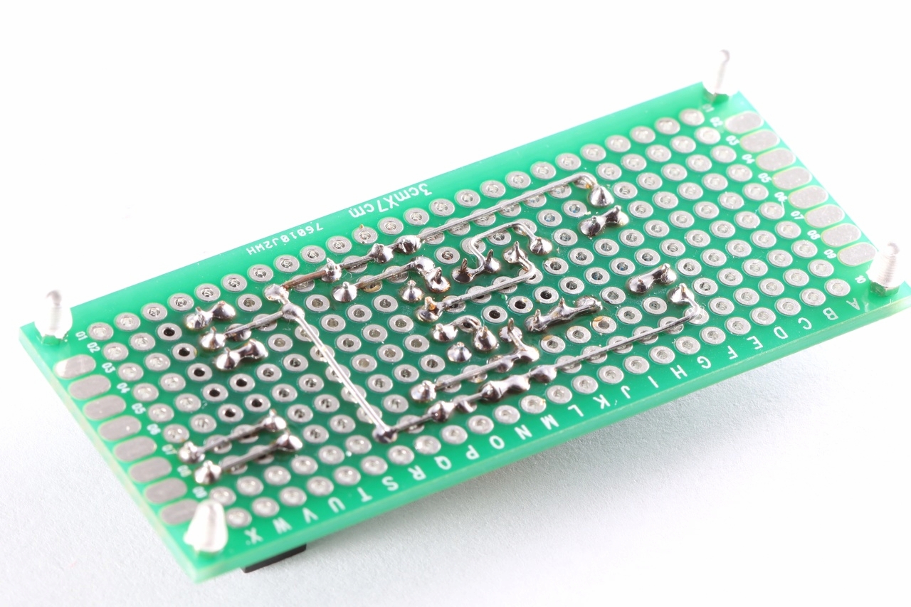
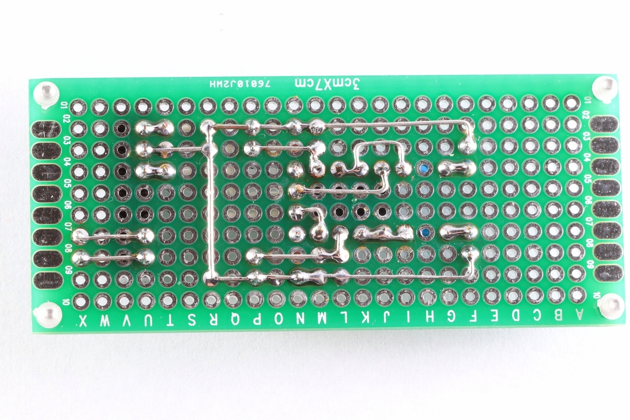
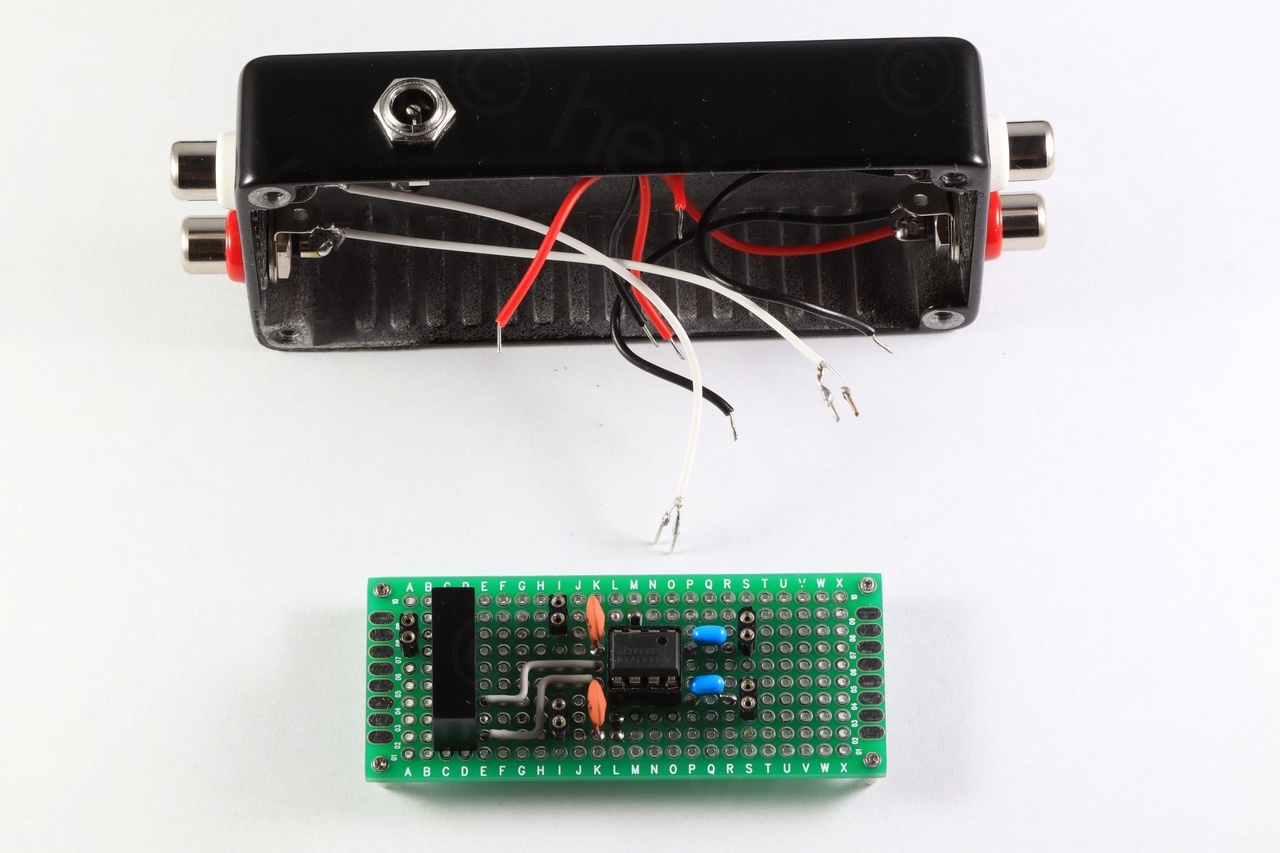
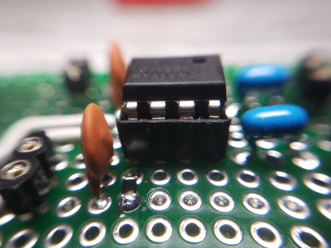
Circuit board
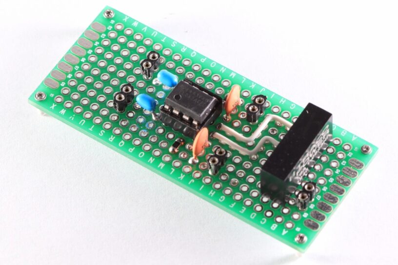
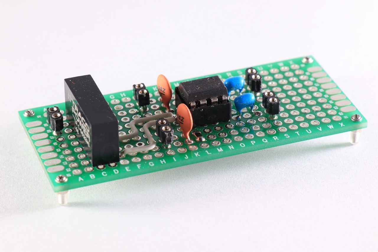
There’s not much to be said here .. some wire stripping, makeshift 2 pin female headers, lots of flipping back and forth and cross checking with the VeeCAD layout. Photos of the assembled board:


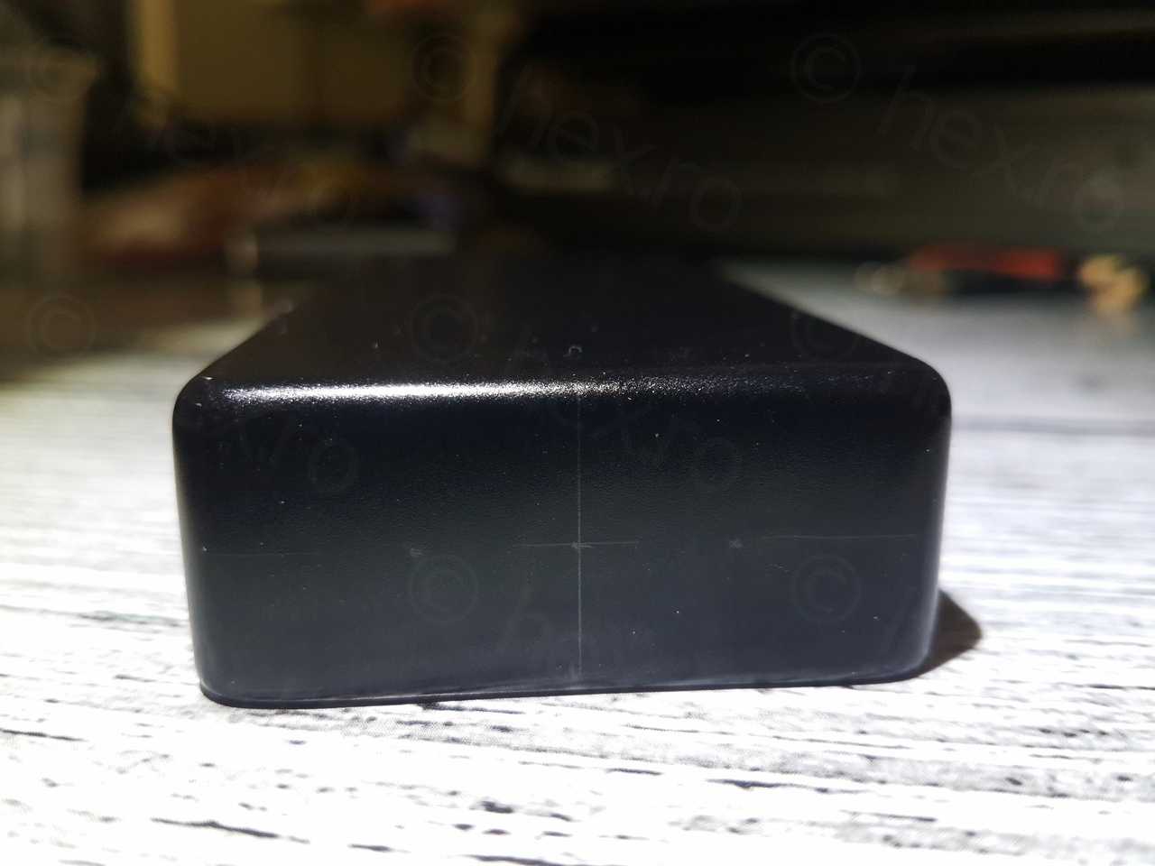
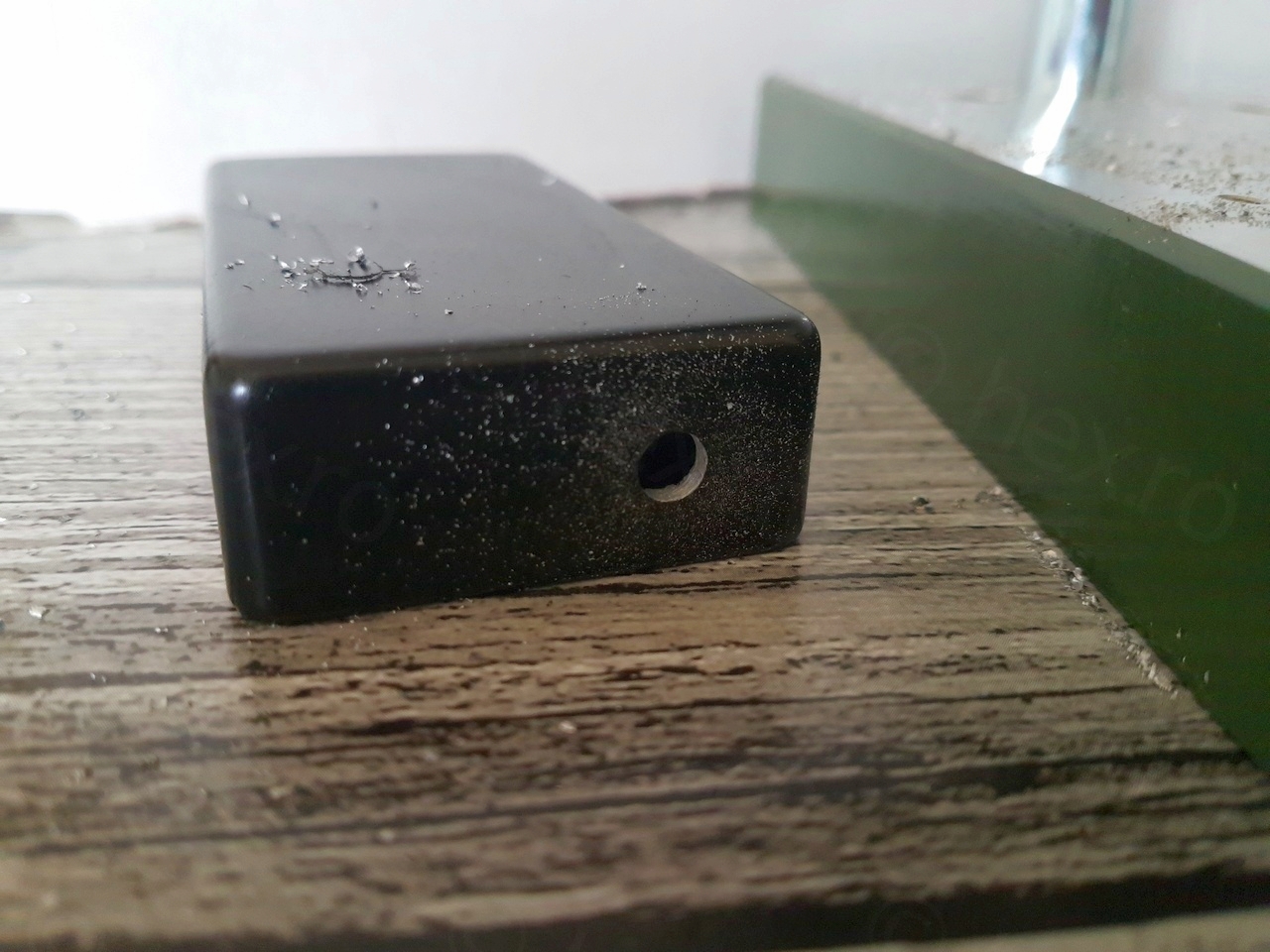
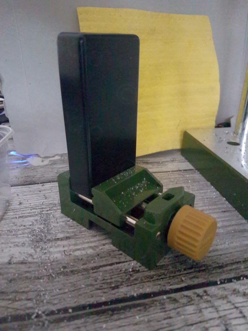
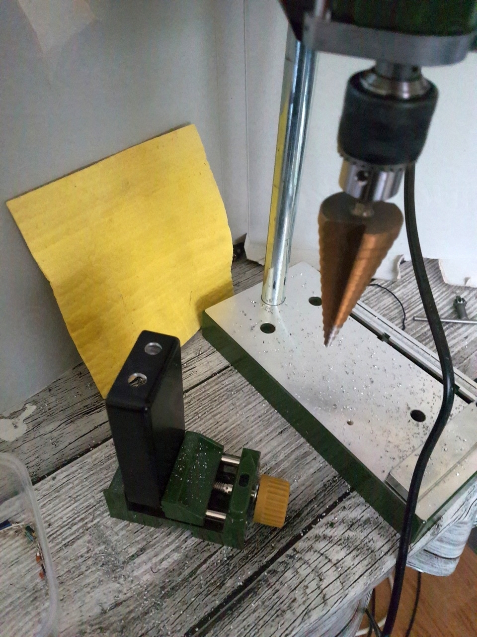
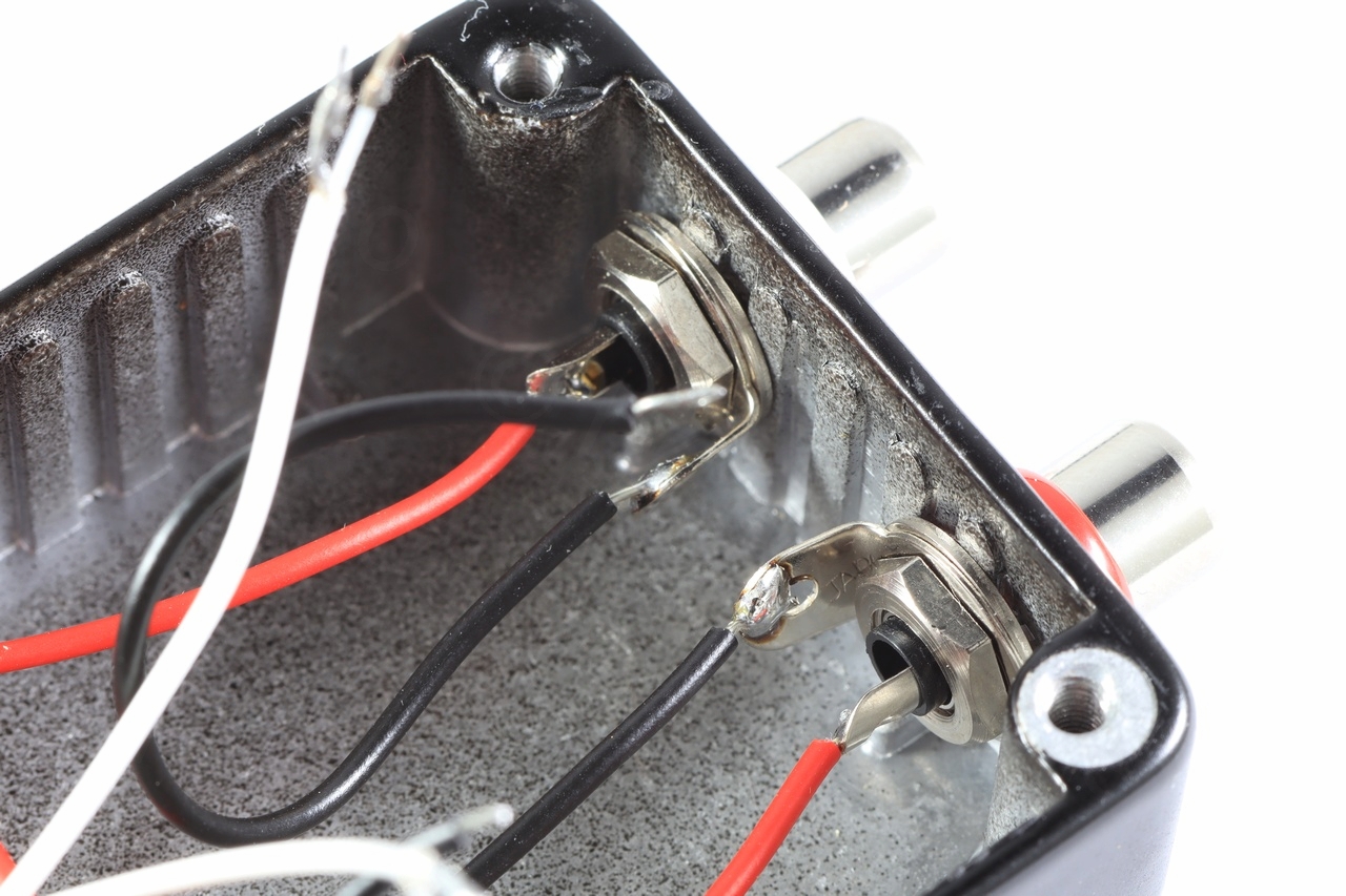
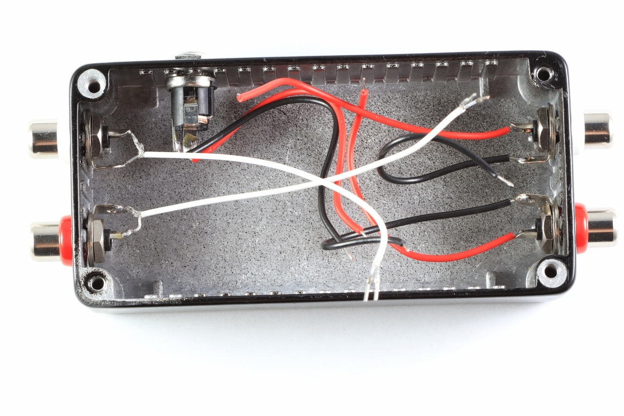
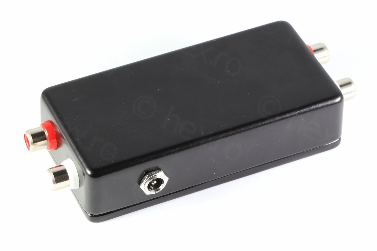
Case
I chose a small rectangular aluminum case that was big enough to fit the circuit board and that had room for the RCA input / output plugs and for the power connector. After few minutes at the bench drill press:
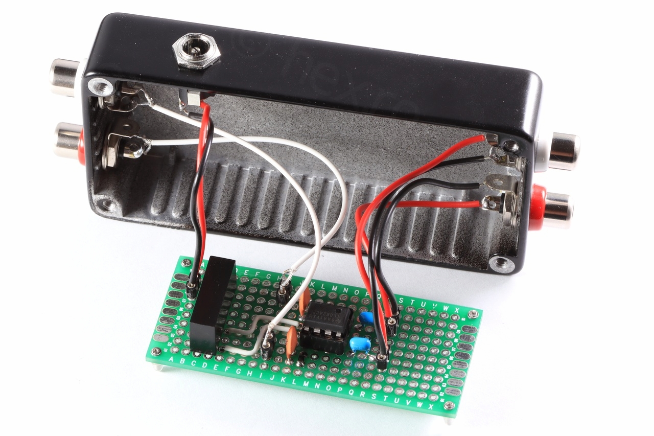
Putting it all together:
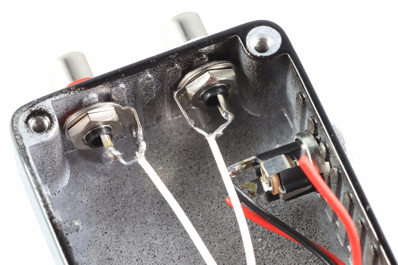

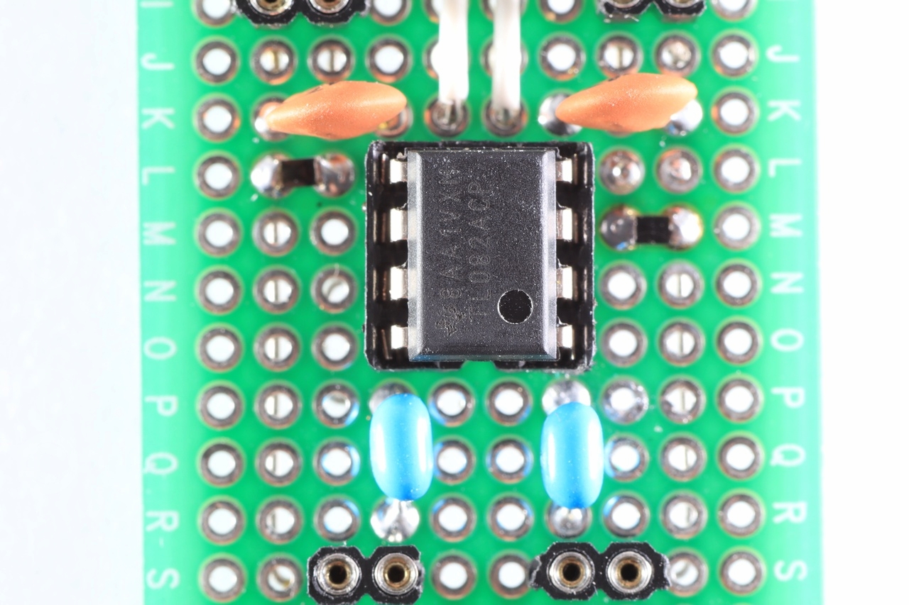
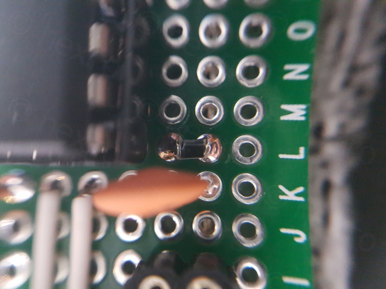
I’ve tried to do some very close shots of the small SMD resistors:
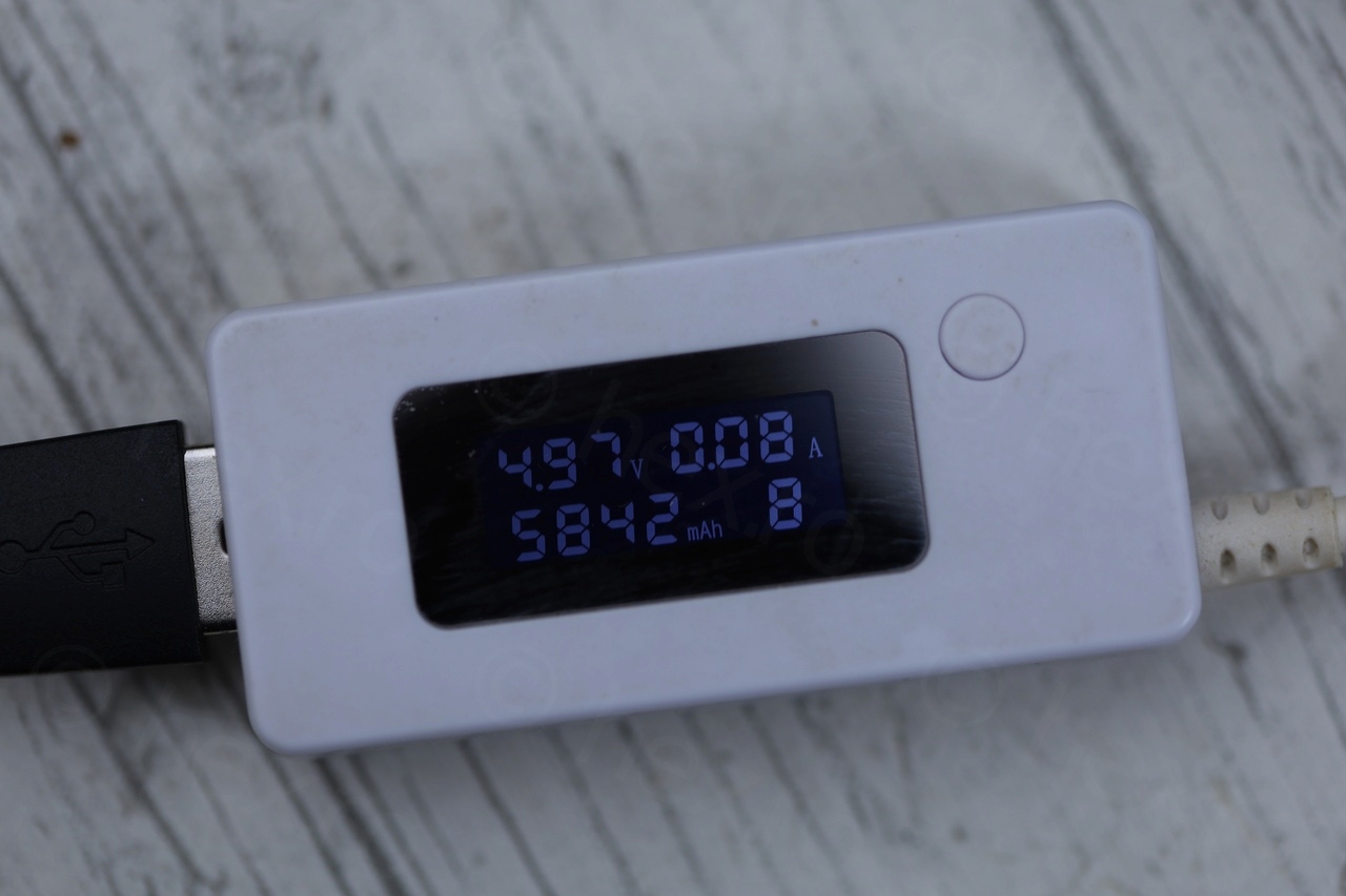
The device consumes about 80mA, measured with a non-accurate USB inline meter:
THD Measurements
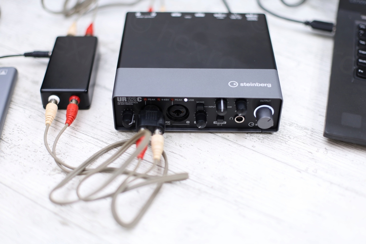
I took some measurements using REW (Room EQ Wizard software) and Steinberg UR22C USB Audio Interface (32-bit @ 192KHz). FFT was applied for a 1kHz signal using with Rectangle window, FFT length of 1M and 16 averages.
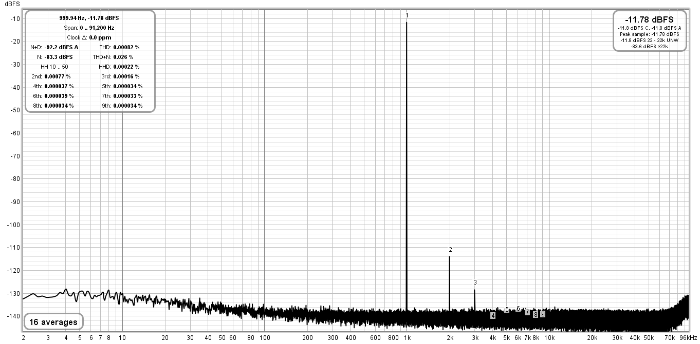
First the loopback – where the UR22C is generating a 1KHz tone and recording it back in loopback mode without the buffer: THD: 0.00082 and THD+N: 0.026
Then the unity gain buffer was introduced between the output and the input – THD increased to 0.00088% (vs 0.00082% loopback) and THD+N is now 0.11%.
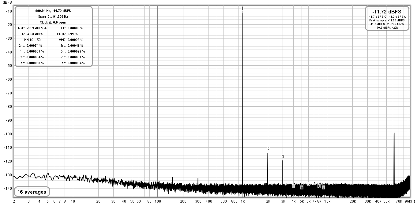
Its interesting that a spike appeared just after 60Khz which I have no explanation for except to maybe attribute it to the Traco DC to DC converter. But I have not tested without it so I am not sure.
The 3KHz harmonic increased and some new spurs appeared at 150Hz and 300Hz.
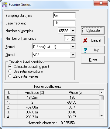
Interestingly, the Fourier Analysis in Tina TI estimates a value of 0.035% for the harmonic distortion, but I can’t select more than 64k samples:
TL082ACP vs OPA2134PA
Since I had some OPA2134PA lying around, I was curious to see what REW says if I just swap the TL082ACP with the OPA2134PA:

THD is almost the same as loopback, at 0.00083% (vs 0.00082% loopback and 0.00088% with TL082ACP), but the THD+N became a little worst, at 0.15% (vs 0.11% with TLA08ACP). Interestingly, the spur at +60KHz was higher, but the ones at 150Hz and 300Hz are less pronounced than with TL082ACP.
I decided to keep the TLA082ACP.
I may build a similar device using the OPA2134PA opamp though 🙂 – they behave almost identical, so why not ?
Caveats
The circuit has no input protection clamping diodes on the inputs. I decided not to install them either – in an attempt to keep noise down.
Renato M Lazzari
One question, if I may: if I understand correctly, this circuit is just to compensate the losses related to the high-pass filter formed by the capsule’s capacitance and the amplifier’s input impedance, right? To compensate for the RIAA equalization applied in the manufacture of the record, one more stage is needed after this, a stage with a small gain since the voltage produced by the ceramic crystal is high, but which accentuates the bass and attenuates the treble, is that it? Thanks.
viulian
My understanding is that the ceramic crystals have a ‘built in’ compensation for RIAA curves as long as you provide them with very high input impedance pre-amp / amp.
I have links to some sources in a different blog post here.
Ceramic cartridges produce enough level output that they “could” be plugged directly into a Line-In. But Line-In impedance is low compared to expectation, so you can’t. Thus, the simplest device that could make a ceramic cartridge work is this type of unity buffer. It conserves the signal level, and it offers very high input impedance. Then buffer output can be plugged into any modern Line-In low impedance amplifier.
I tested both this as well as the velocity adapter, and frankly, I like more the velocity adapter. But I wanted to give it a go, just to hear how it is. Probably, the built-in cartridge compensation is not perfect. I had to compensate with the tone controls a bit.