Table of Contents
- Introduction
- Replacing a broken DIP-28 Socket
- Battery corrosion cleanup
- 72-pin SIMM metal tab replacement
- Benchmarks
- Other observations
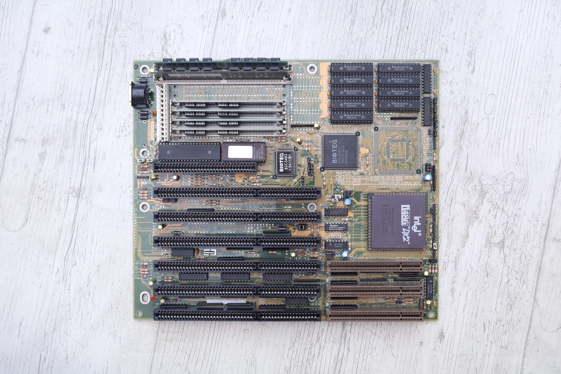
Introduction
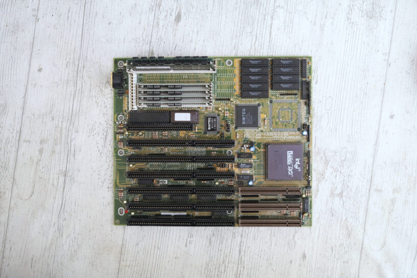
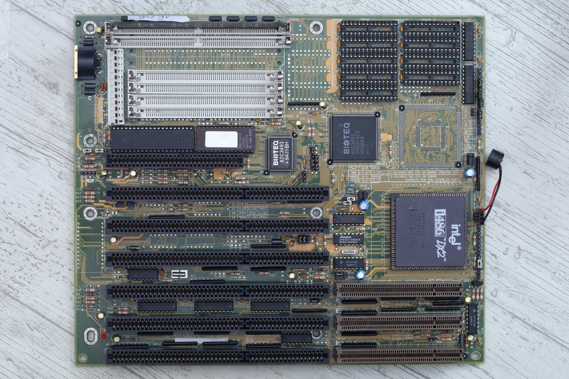
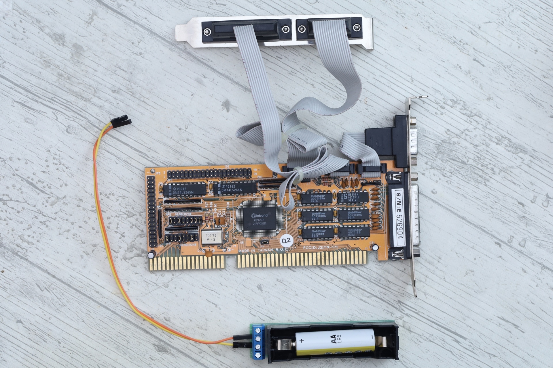
This board was sold as a bundle. With it, an Intel 486-DX2 CPU, 1 x 16Mb 72-pin SIMM DRAM module and an IDE controller card. There were no cache chips installed, but the asking price was better than others. The board was described to be in good condition.
The troubles were visible once it arrived:
- The metal clips of the 2 x 72-pin SIMM sockets were messed up.
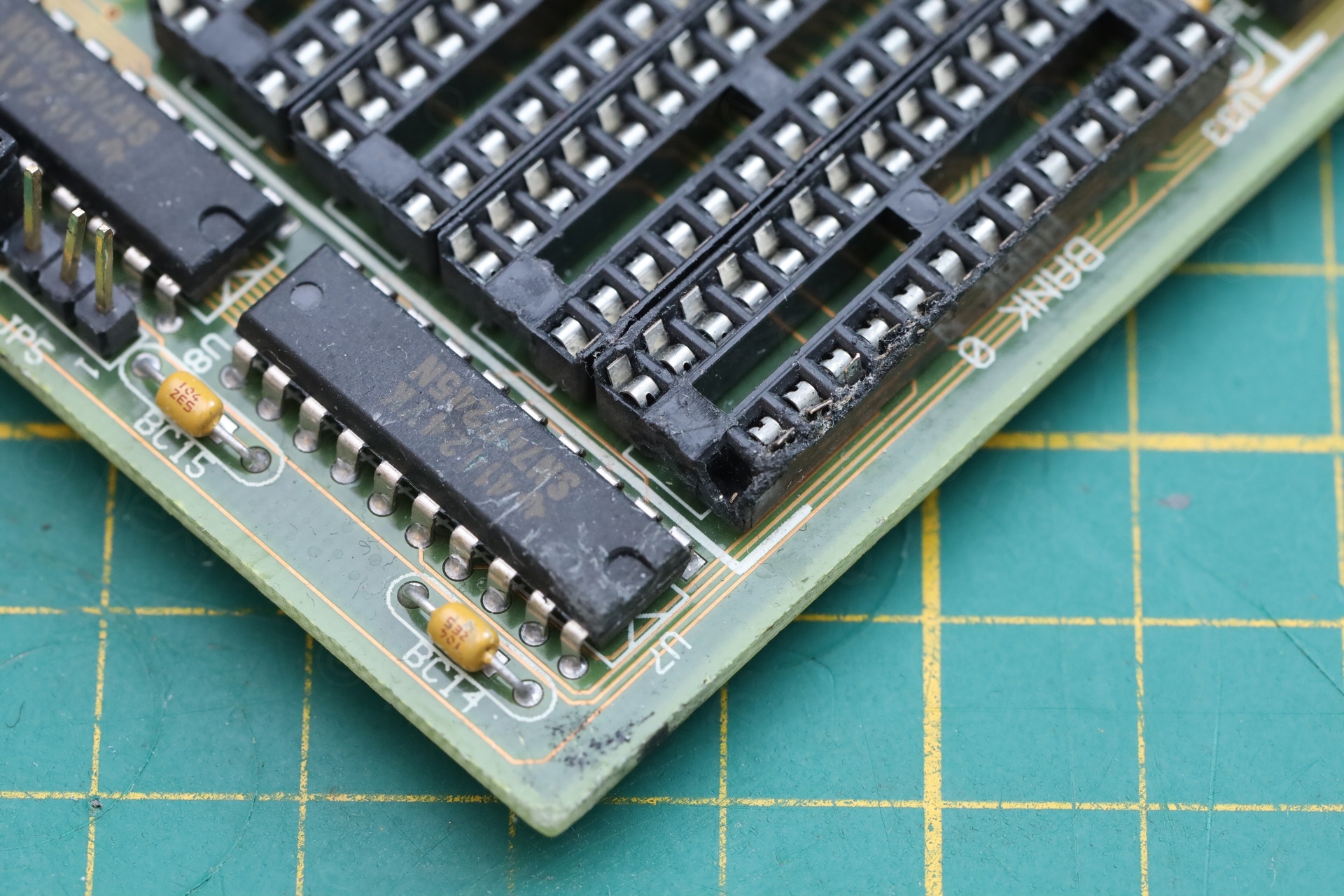
- One of the 28-pin DIP socket for cache chip was damaged and missing a pin.
- The BIOS chip looks like a standard EPROM.
The board did work but I was still undecided if I should keep it. I wrote to the seller. He was kind enough to offer a discount, so … I kept it and tried to refurbish it.
The DIY external battery setup was surprising. A single AA battery in an 18650 holder, which had its tabs over-extended to retain the smaller AA battery. I discarded the improvisation. I appreciated the ingenuity, but 1.5V is too little for an external battery, I feel better with more than 4V. I also appreciated the little buzzer the seller left attached to the motherboard.
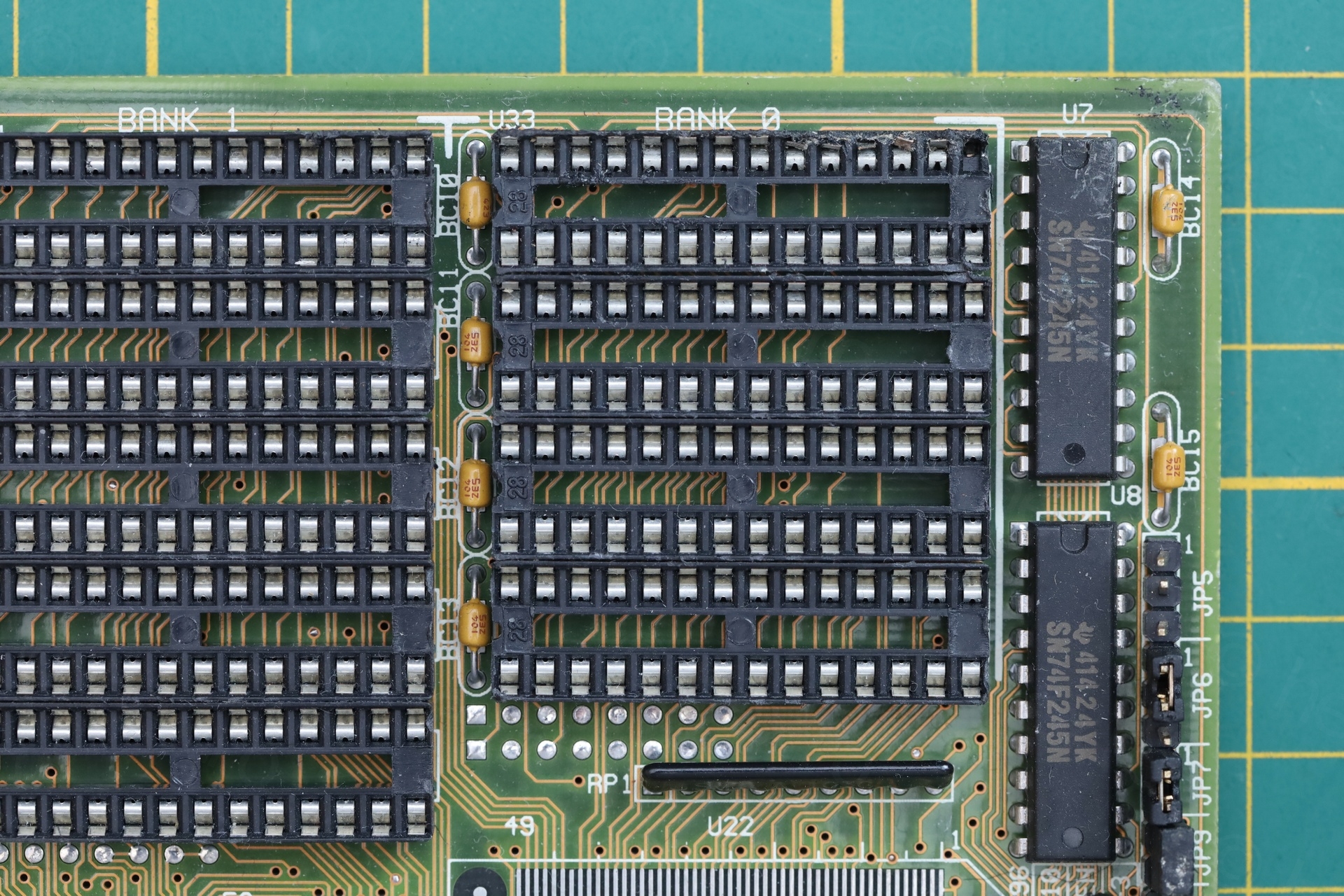
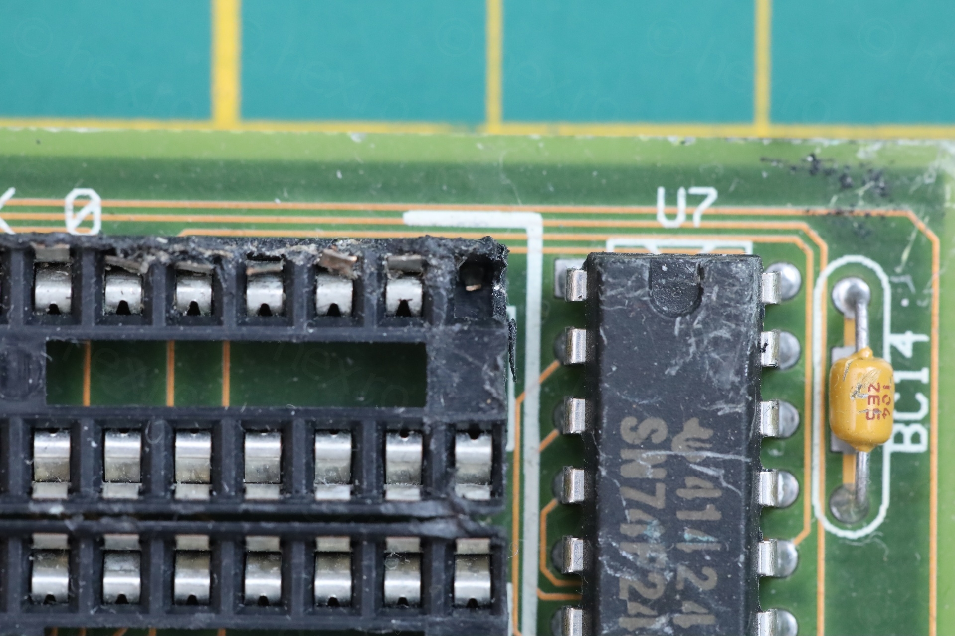
Replacing a broken DIP-28 Socket
A closeup to the damaged socket:
I ruled out the electrical de-soldering pump. While it would be very easy to remove the socket, my pump clogs if I run it at 350C – I have to run it at 400-450C. At these high temperatures, it burns the motherboard (or scratches) as I try to wiggle the tip around the pins.
First attempt was using an copper wire bent in an U shape. I figured it would be enough to take the socket out of the board …
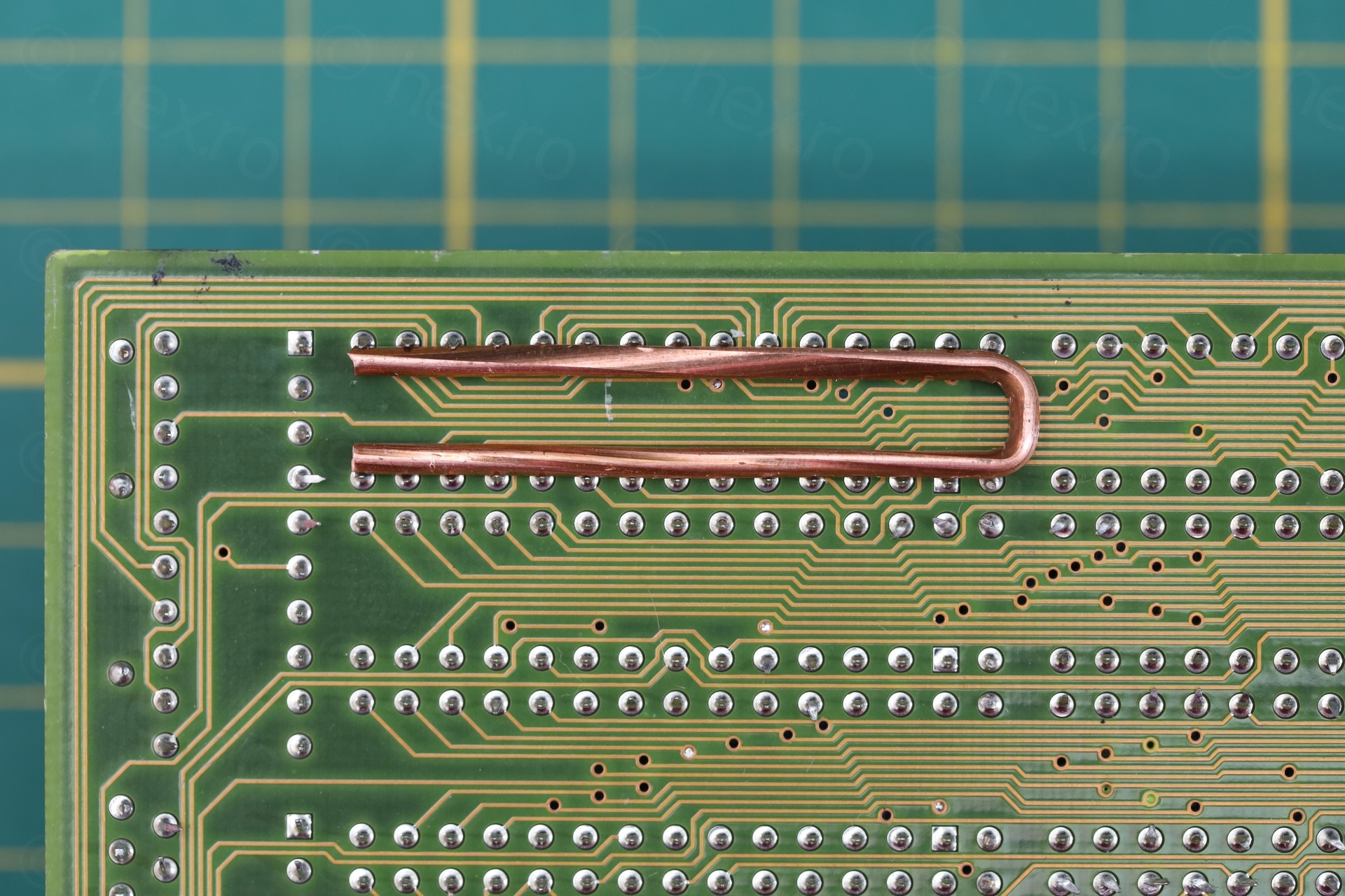
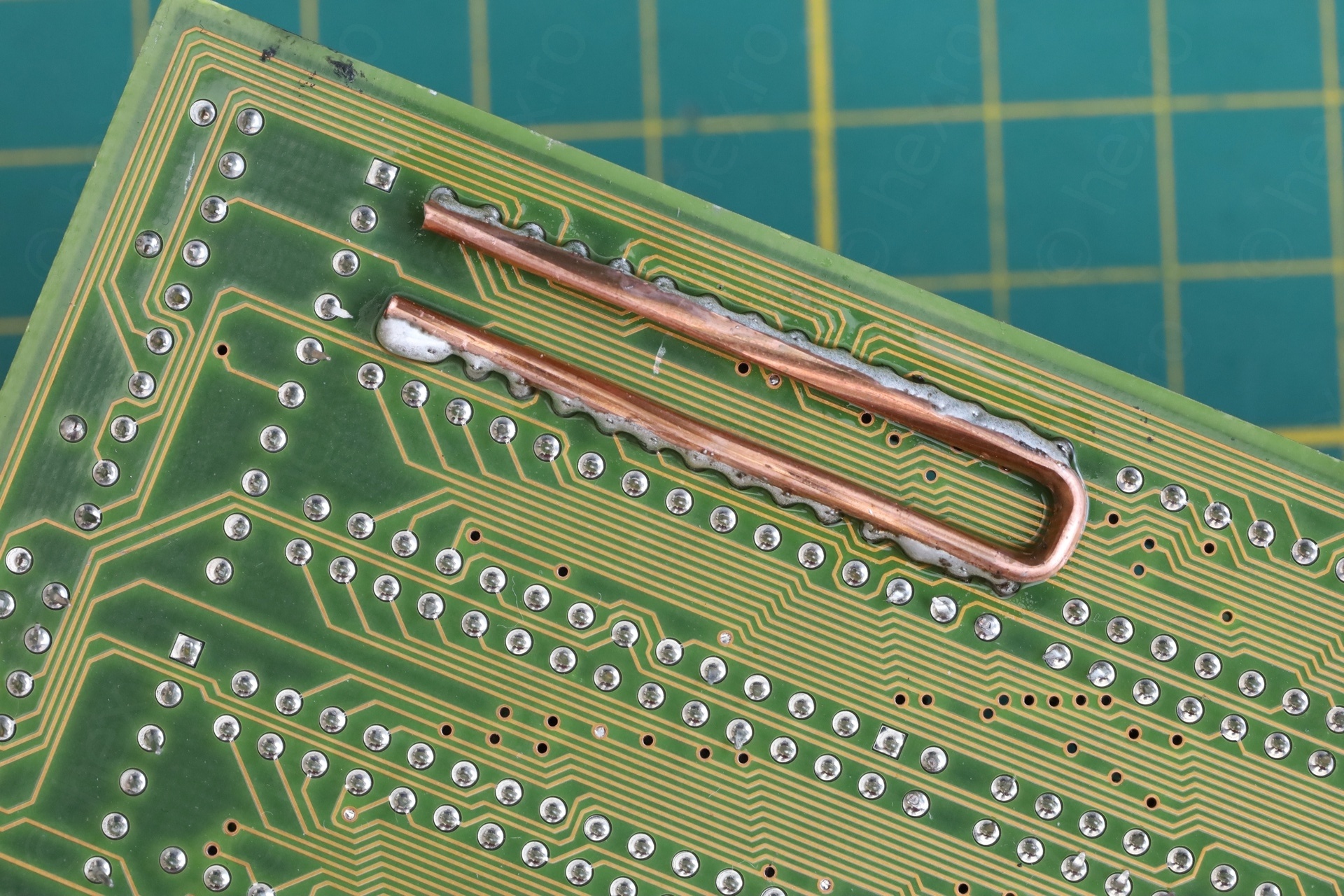
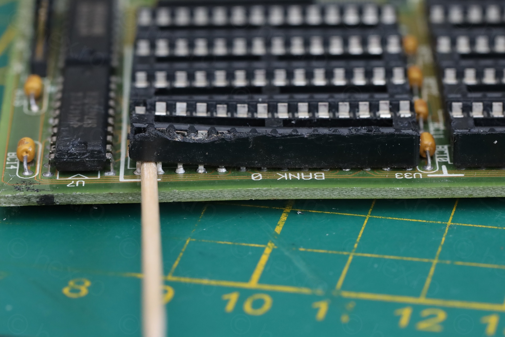
… except, it wasn’t. Once solder melted, there was nothing to keep the copper wire attached: moving the iron also dragged the wire around. The wire was also not perfectly straight. Putting pressure on one spot lifted it from another. Briefly, I would have to break many toothpicks to get the socket out.
In hindsight, I should have used some round copper wire and not the twisty one I had. And one or two loops against some pins to give it some anchor points.
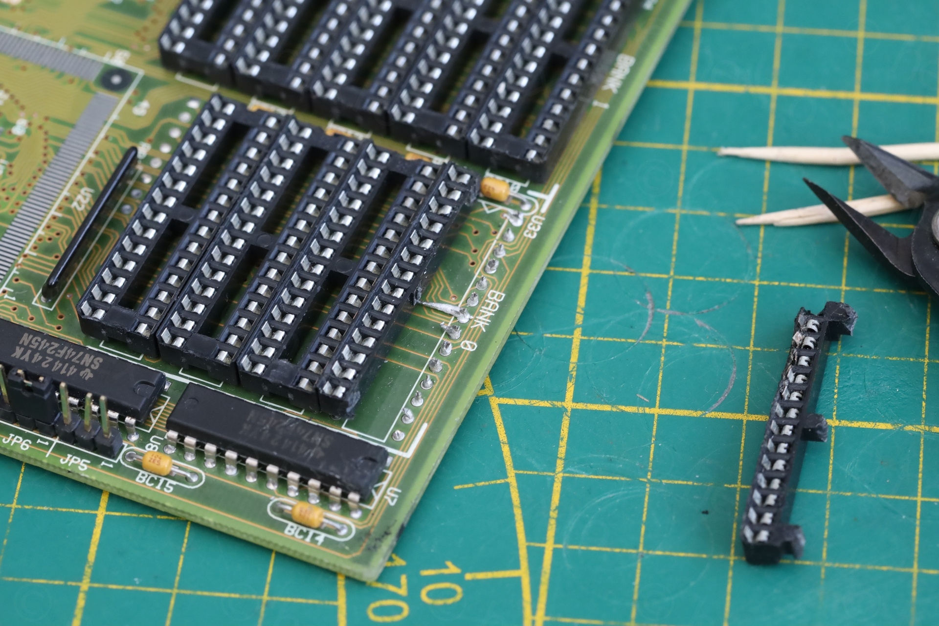
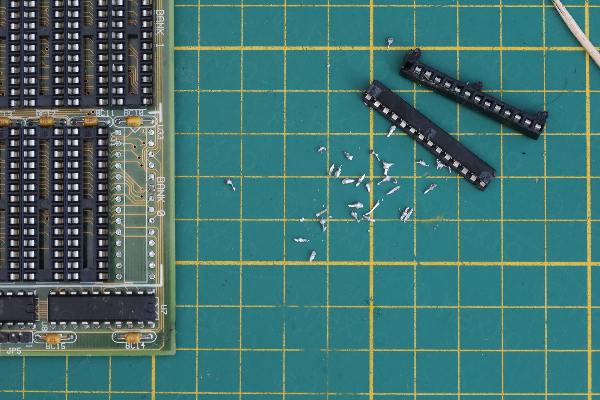
Second attempt was to snap the connecting bridges that keep the two long sides (of the socket) together. Then wigging each long side left and right until metal fatigue kicked in. The remains of each pin can then be easily de-soldered. Absolutely no marks on the motherboard:

Soldering a new DIP-28 socket was then easy:
Battery corrosion cleanup
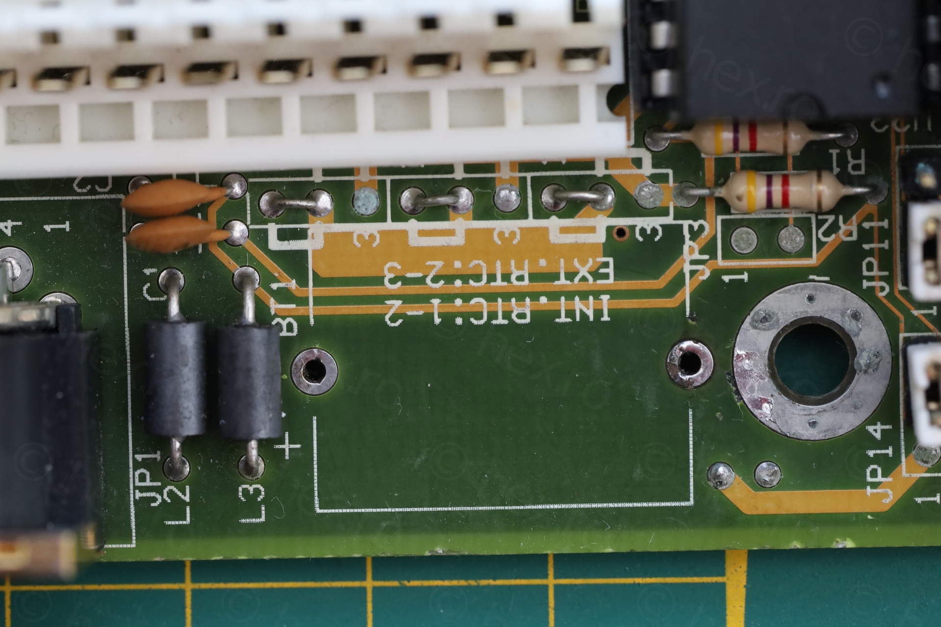
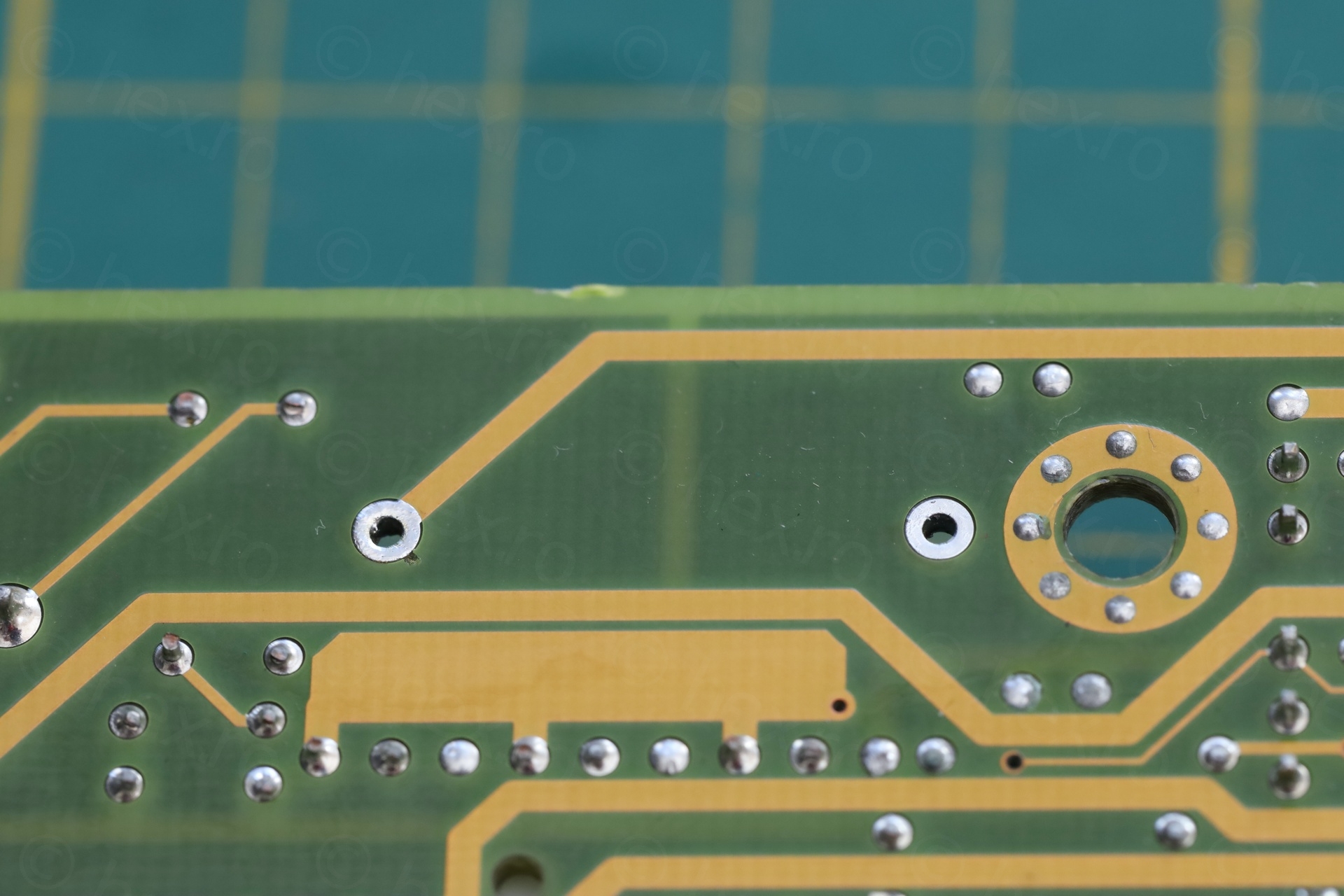
Thankfully, the previous owner cut the battery before it caused too much damage. Some thin traces of corrosion were still visible. The battery pins (or what remained of them) were still left on the board.
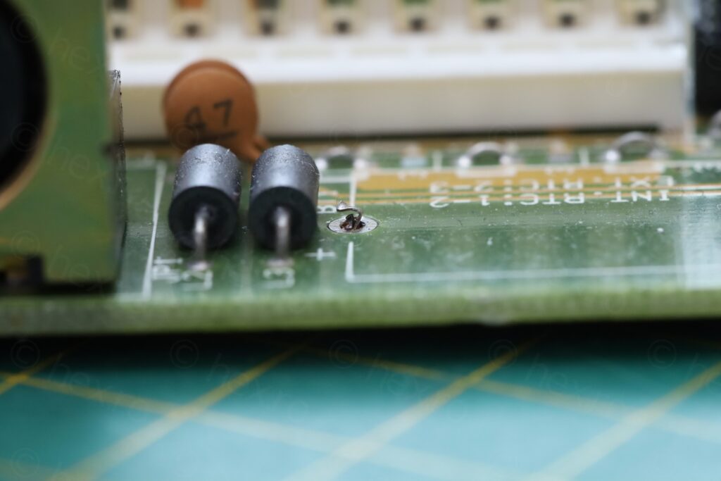
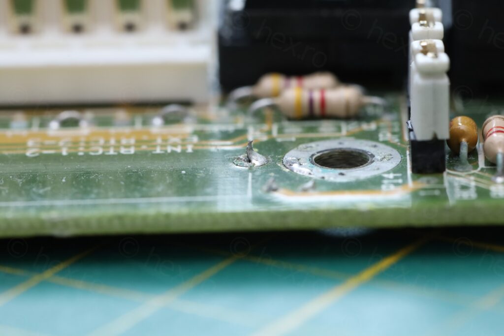
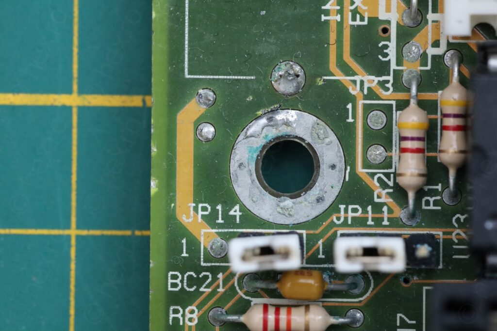
Vinegar followed by IPA for the corrosion + cleanup of the on board battery solder pads:
I will not mount any new battery. When I need to use the board, I’ll attach an external battery since the motherboard has the header for it.
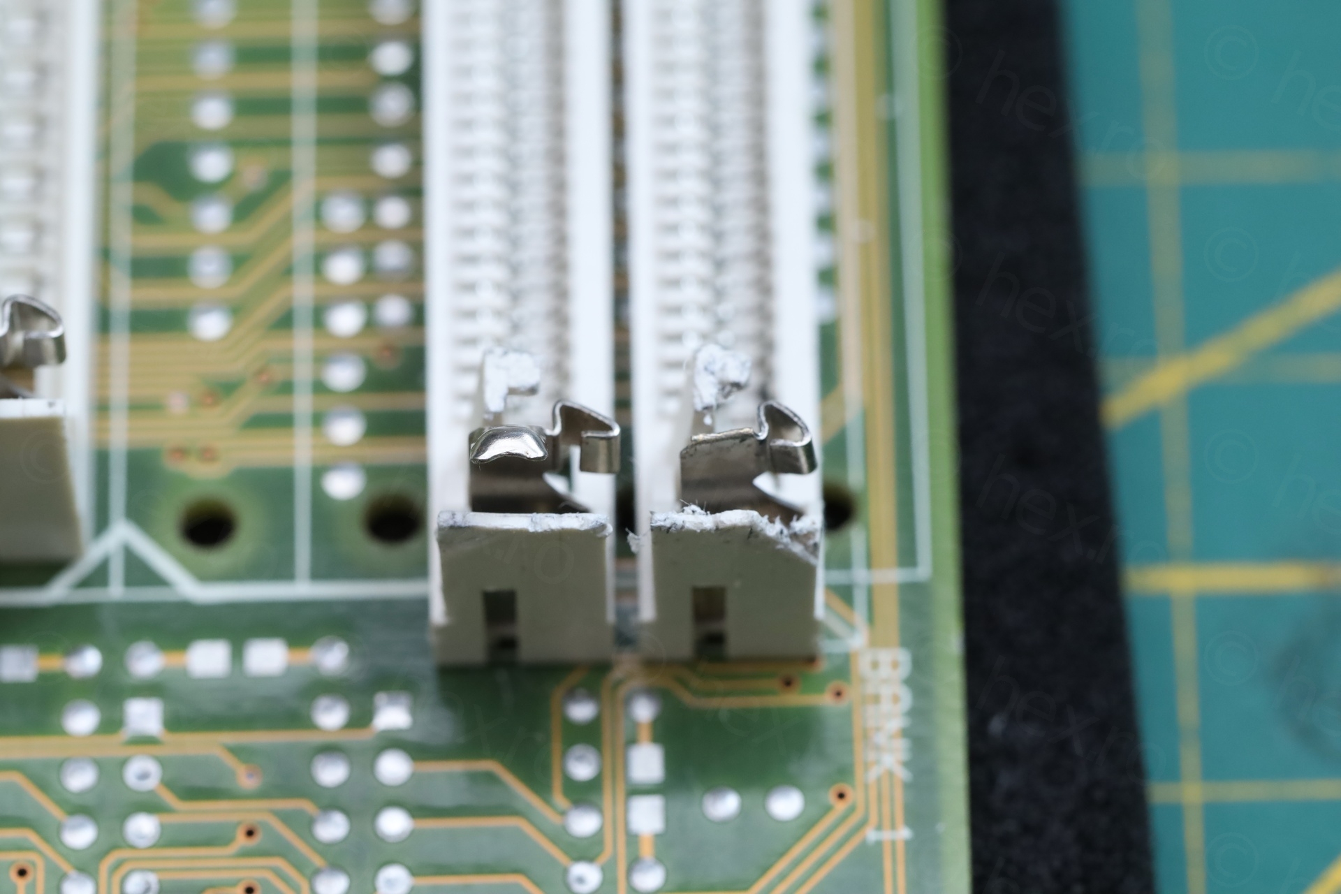
72-pin SIMM metal tab replacement
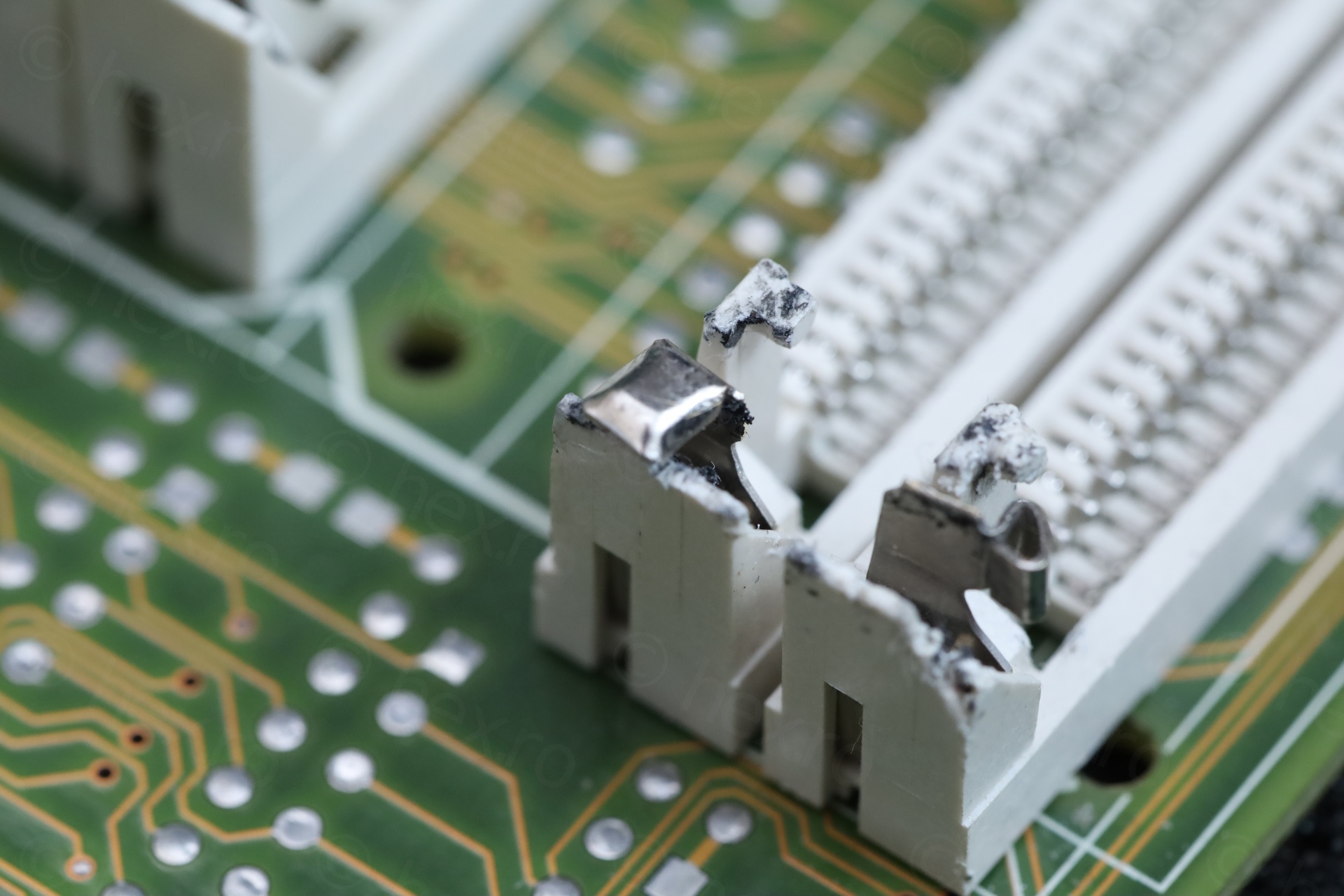
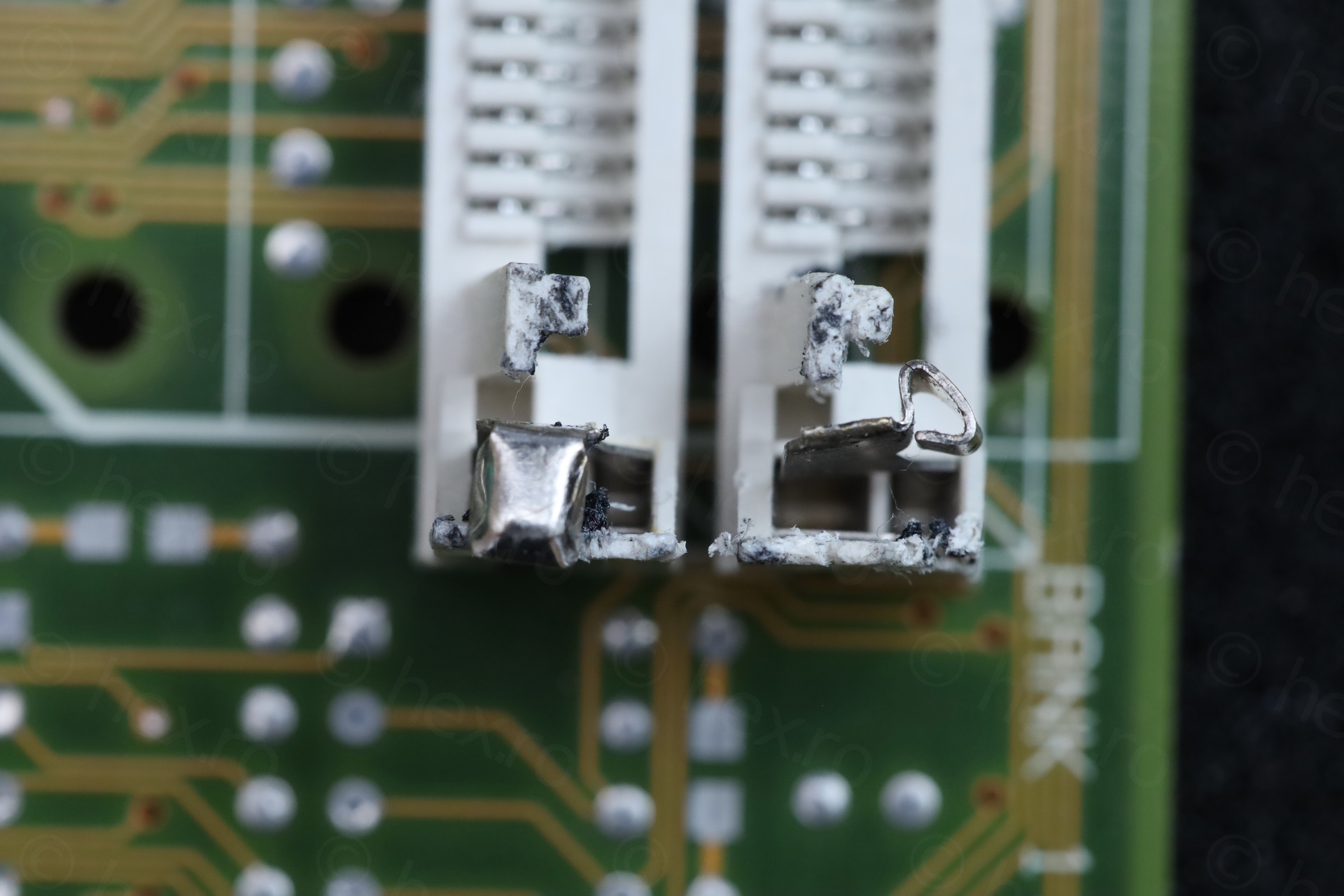
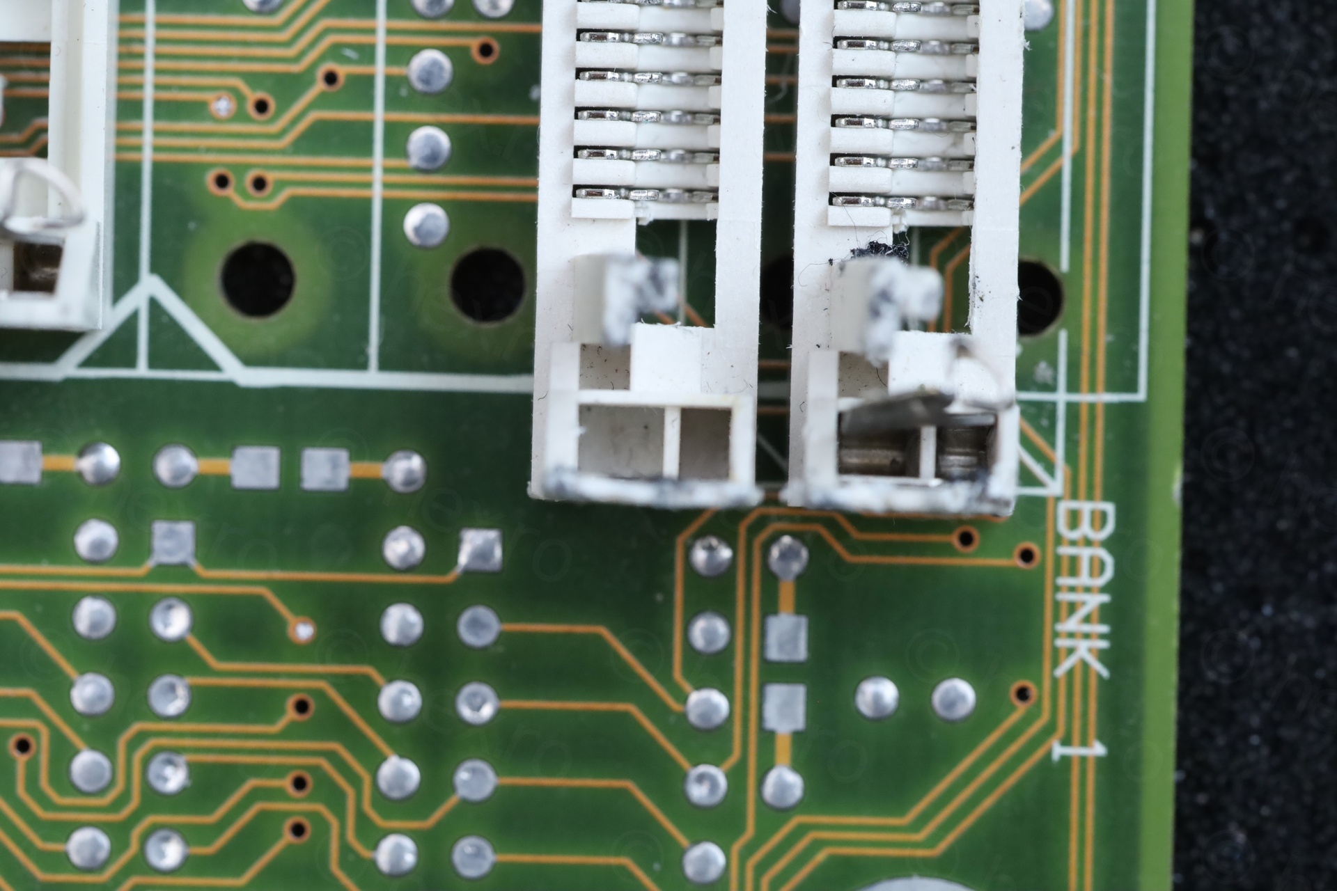
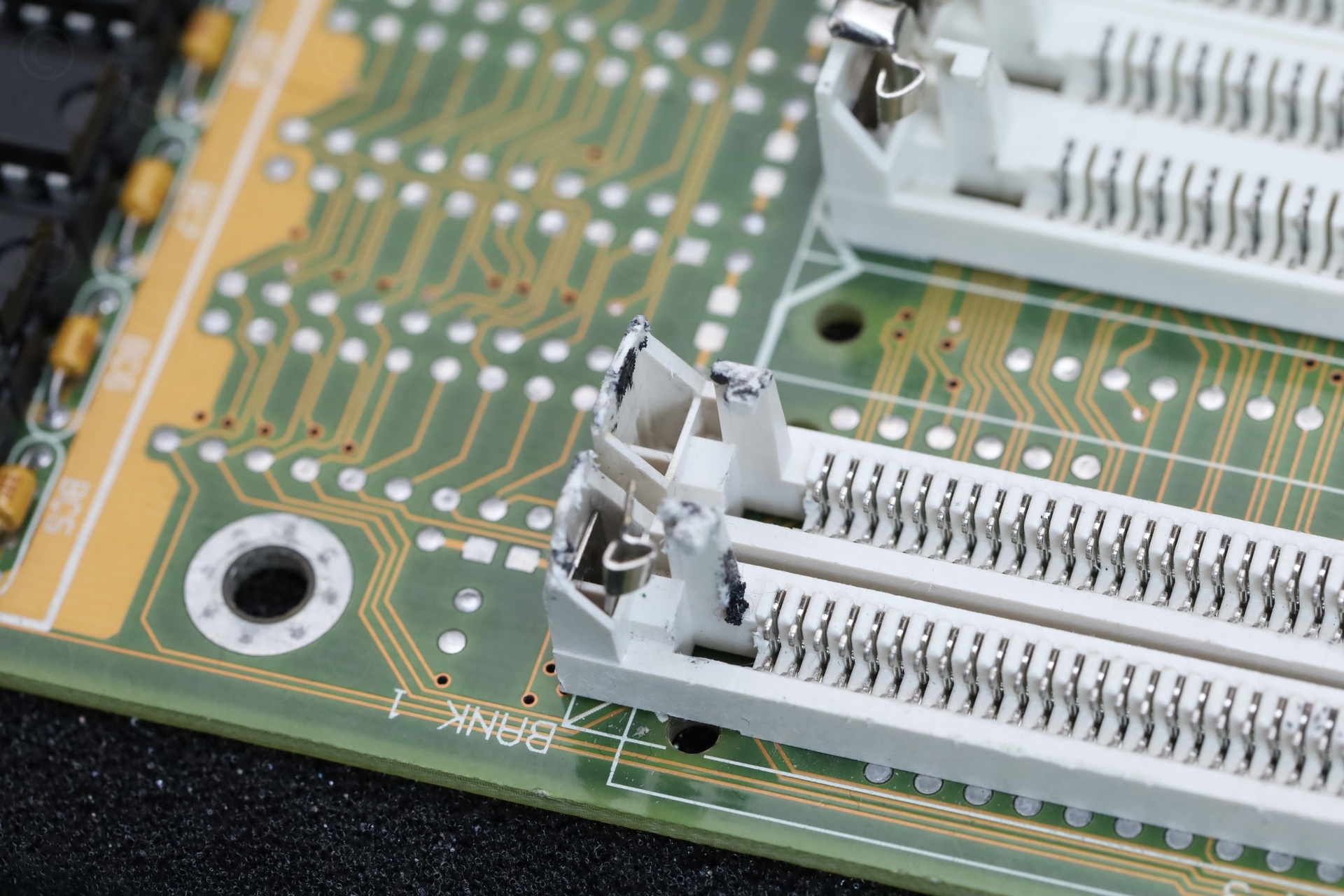
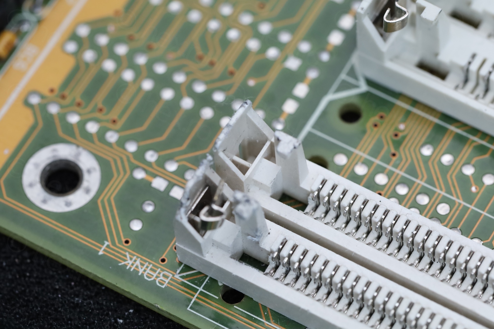
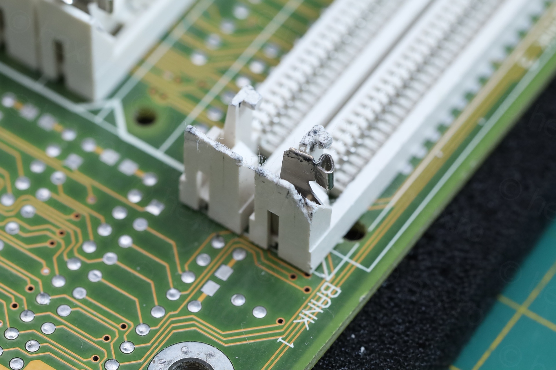
The 2 72-pin SIMM sockets were not in good condition.
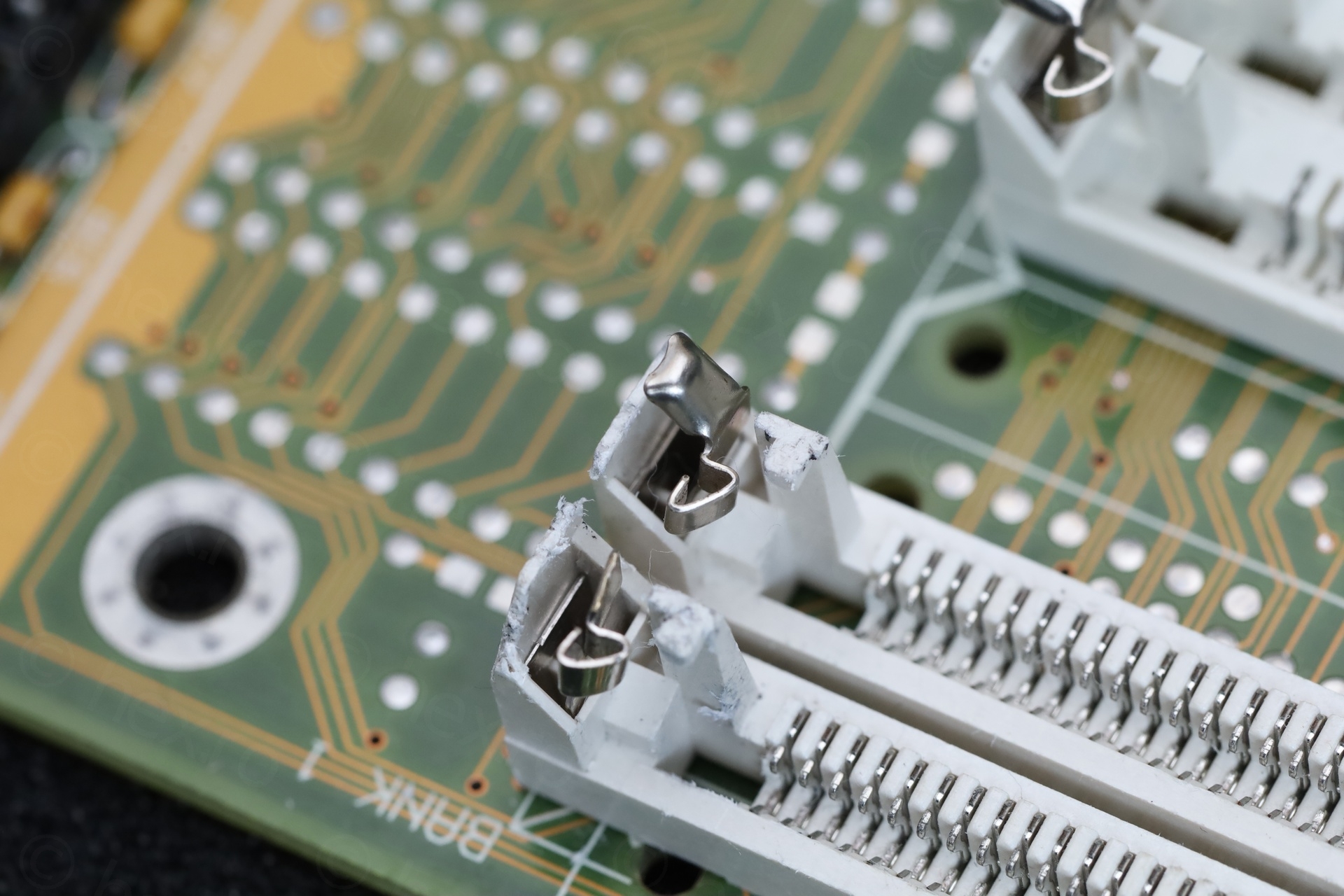
The one towards the exterior could still latch the memory module in place, but the metal tabs were missing the small bit at the top that makes it easier to grab and pull them. The socket towards the interior of the motherboard couldn’t even latch a module in place, one of the metal tabs was missing the actual latching bit. There was also some black gunk on them, similar to what you get when old belts melt.
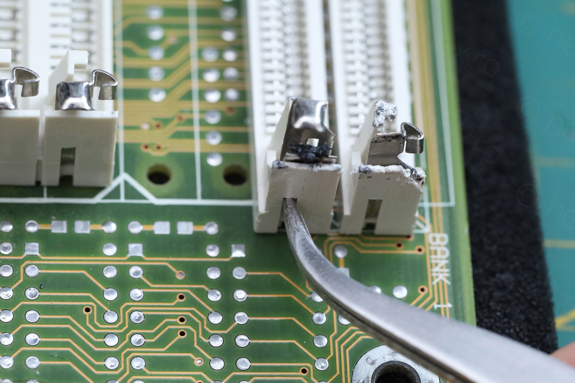
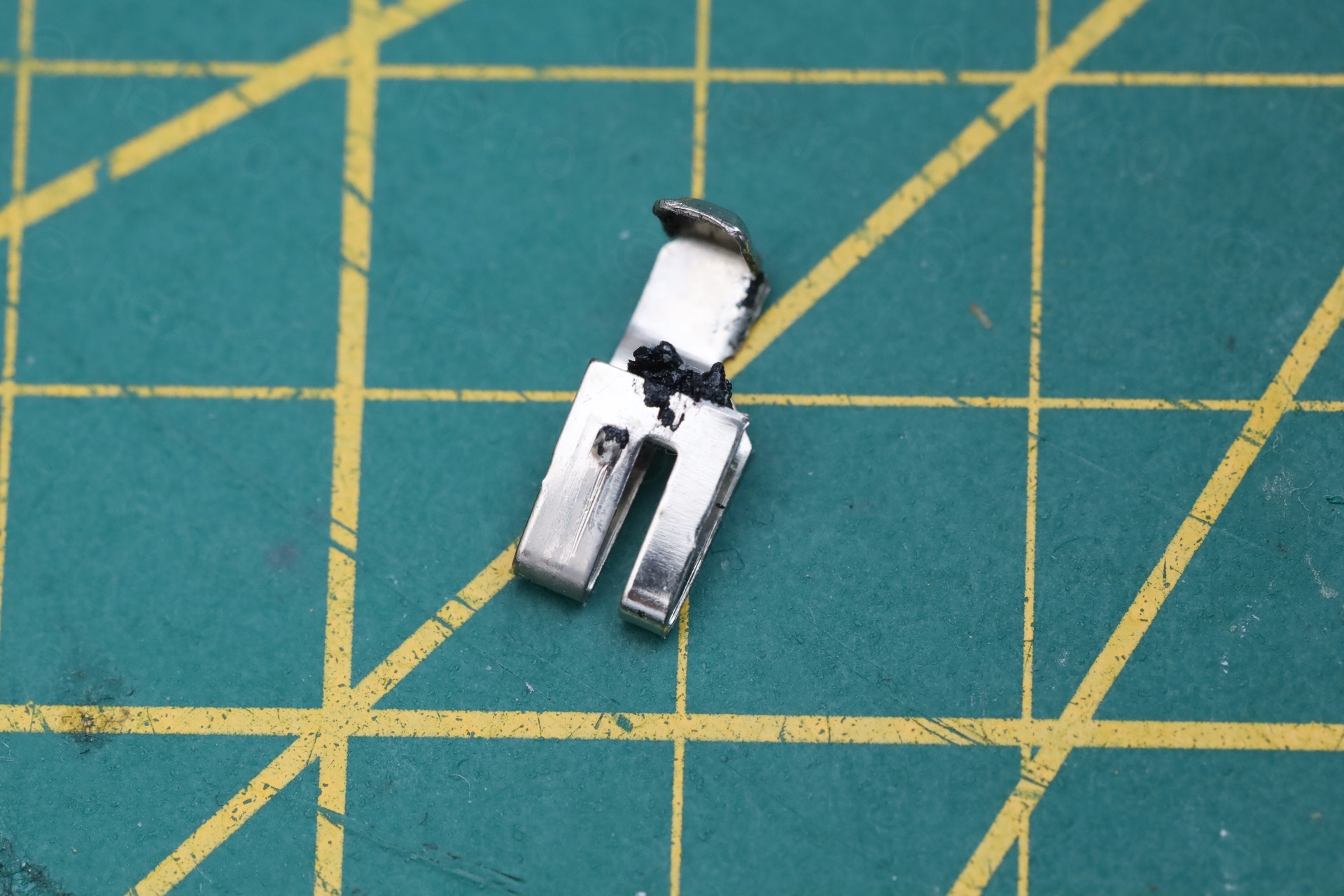
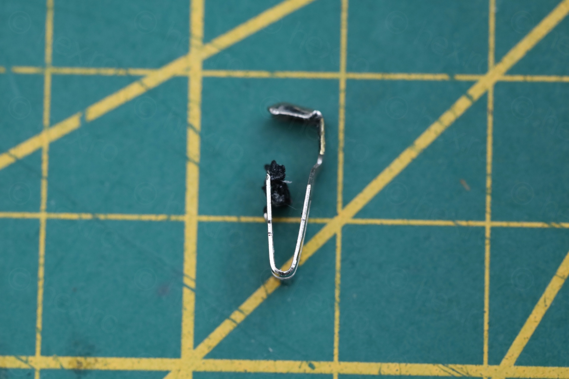
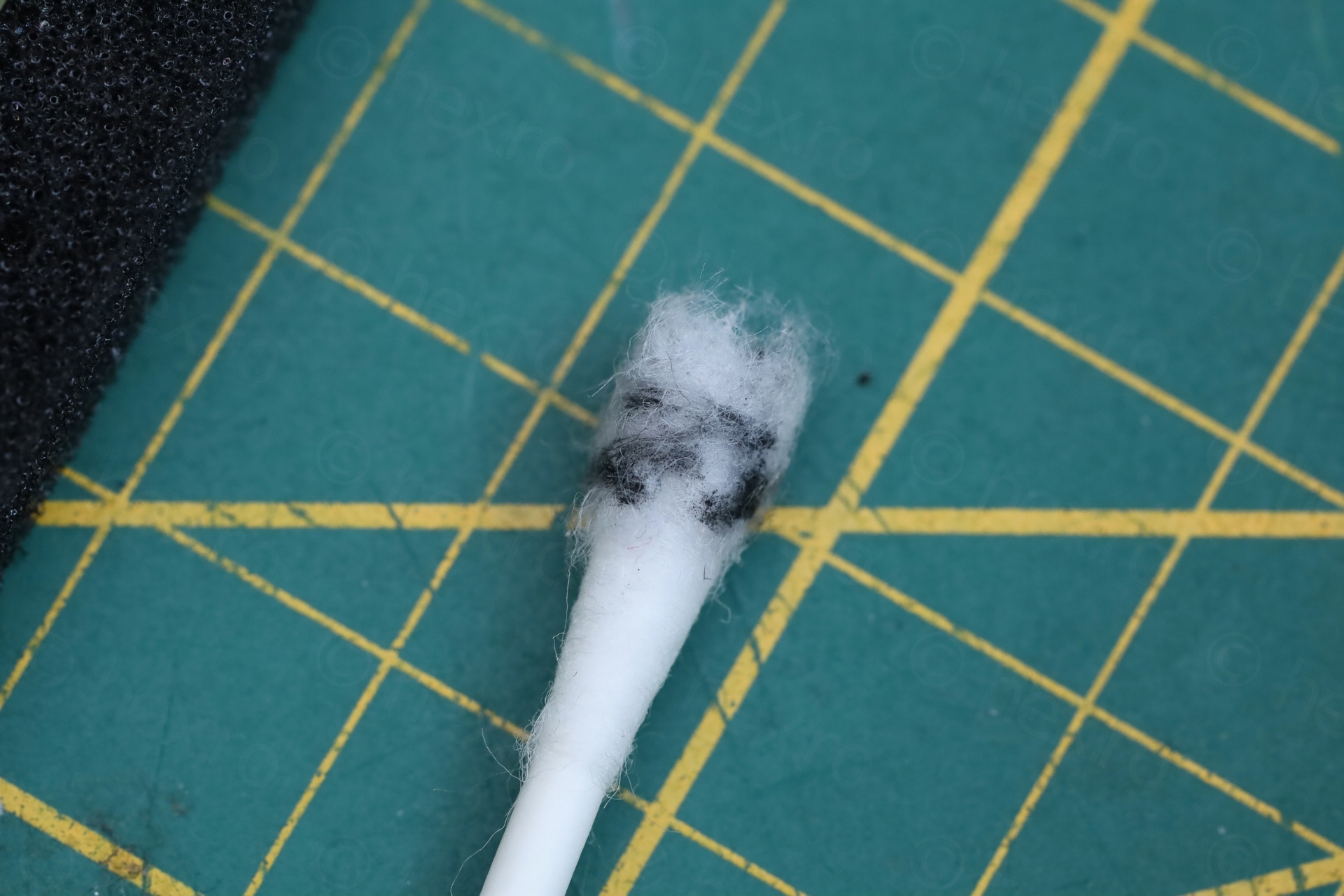
I didn’t know metal tabs could be extracted, but I looked carefully. It seems you can, they have their own metal tab to keep them from lifting up. Using some bent tweezers, I was able to push that little tab inwards and also push the whole metal tab upwards.
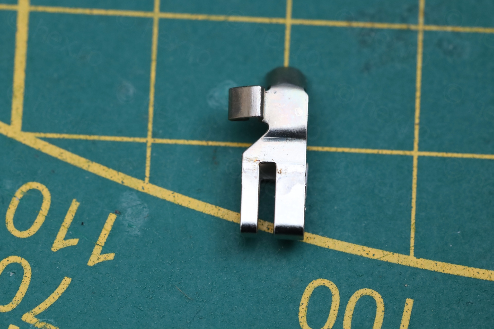
I salvaged a replacement tab from a donor motherboard:
Benchmarks
The remaining thing to do was to test the motherboard.
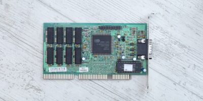
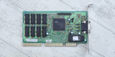
I populated the cache chips sockets with some MCM6206CP20 ICs, salvaged from the same donor motherboard. Memory was a combo of 4 x 30pin 4Mb modules, and 2 x 72-pin 16Mb Single Sided modules, totaling 48Mb. Video card was a Cirrus Logic CL-GD5426 VLB, with 1Mb of RAM.
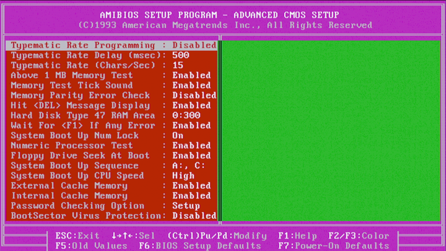
The BIOS settings for the Fastest config (Cache Read 2-1-1-1, etc…):

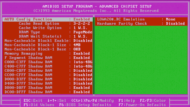
And the settings for the AUTO Config Enabled (Cache Read 3-2-2-2, etc…):

Results from few tests below:
| Test | Fastest | AUTO Config Enabled |
|---|---|---|
| TOPBENCH | 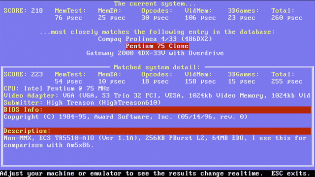 | 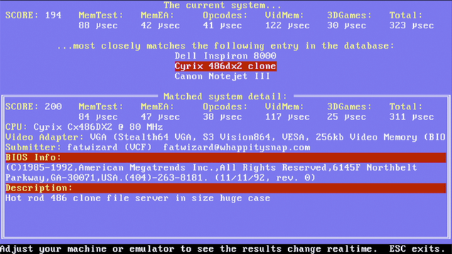 |
| SpeedSys 4.78 | 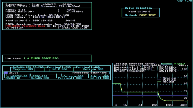 | 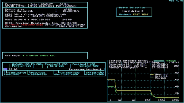 |
| CacheCHK | 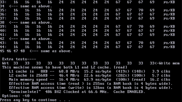 | 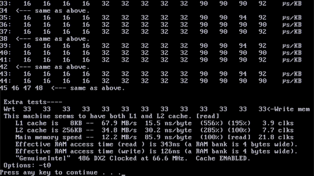 |
| ctcm v1.5b/t2 | 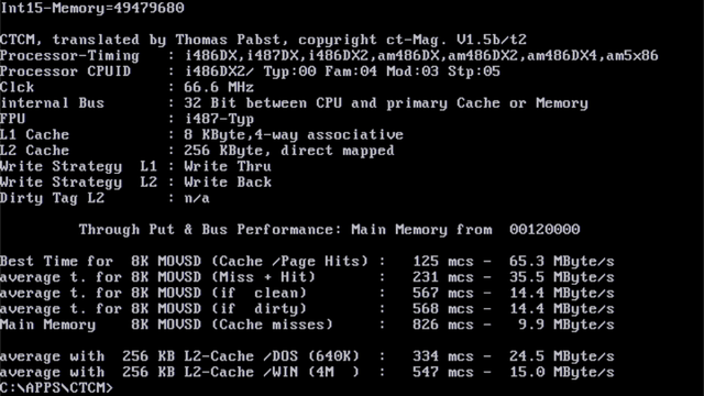 | 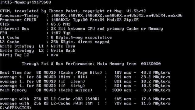 |
Although all benchmark tests run fine, I had a crash when copying one 128Mb CF card to another, towards the end of the copy. When using fastest settings. Since I didn’t want to wait so long, I switched to AUTO Config Enabled, and then the copy ran just fine. I did not investigate more.
Other observations
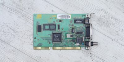
Cirrus Logic CL-GD5422 / CF to IDE adapter incompatibility
This motherboard has a weird quirk – a Cirrus Logic CL-GD5422 ISA (16bit) video card and the CF to IDE adapter, they can’t work at the same time. With the IDE controller card plugged but without the CF to IDE adapter connected to it, the video card is recognized and there is video. However, once I plug the CF to IDE adapter into the IDE controller, the video card is not recognized anymore – only beeps. I don’t have many ISA video cards, but it works fine with an OAK OTI-077 or with a Trident ET4000AX. It also works fine with a generic Cirrus Logic GL-5426 VLB card. Jumpers are set correctly for CL cards – according to the manual: JP9 -> 23 and JP10 -> 12.
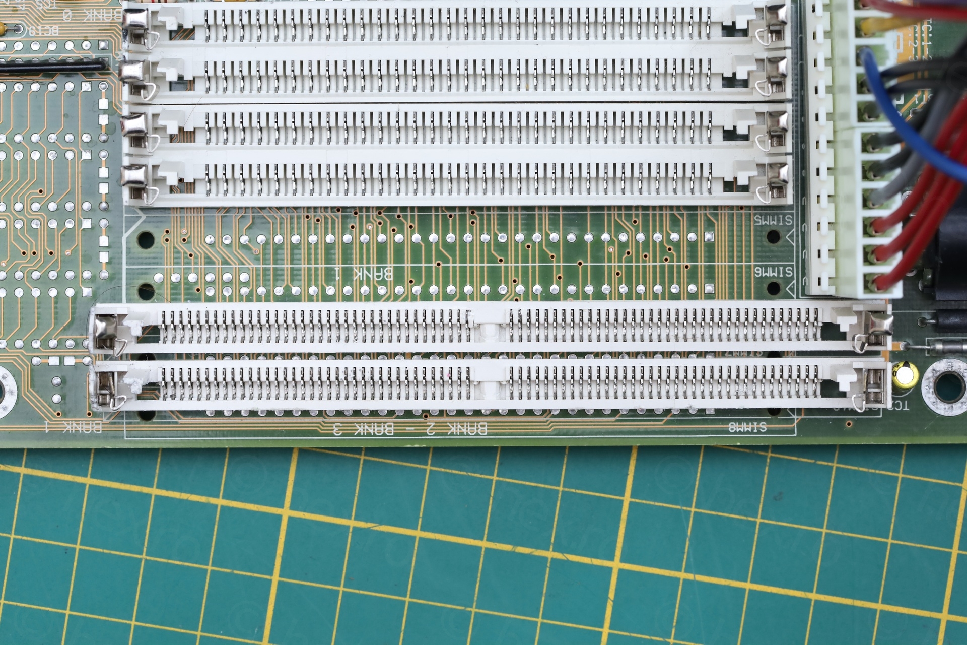
Double sided DRAM memory size and SIMM9 socket
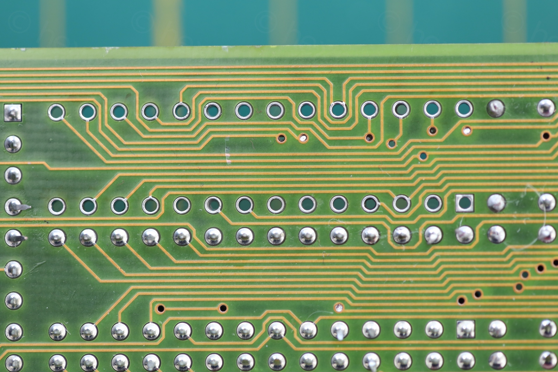
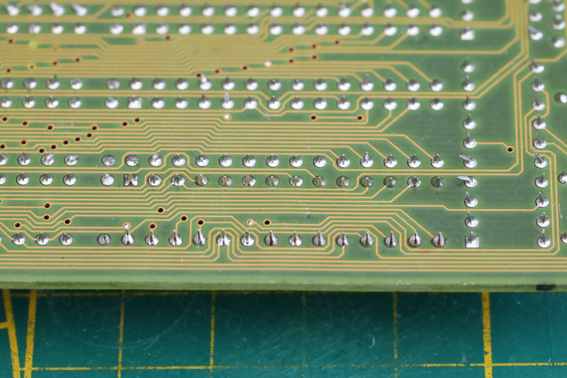
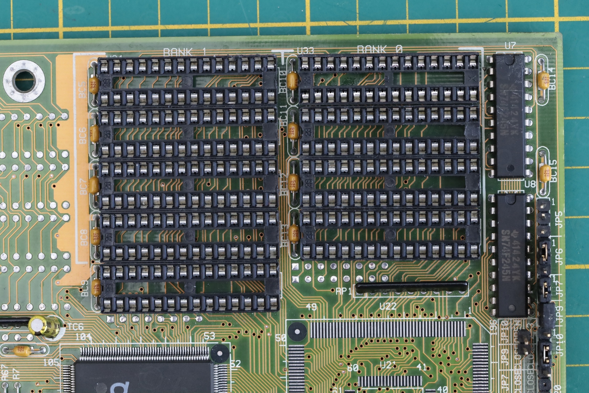
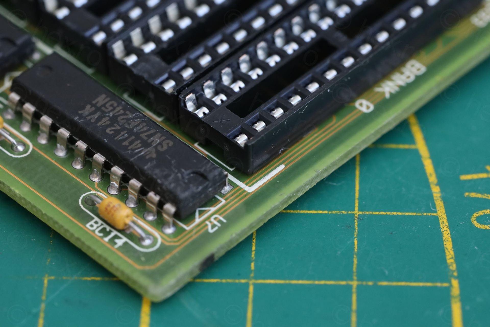
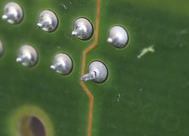
Another problem is that the motherboard is unable to detect the correct size of double sided DRAM modules installed in the SIMM9 socket (72-pin). The manual is not very clear, nor my knowledge about banks – but SIMM9 is defined as BANK 1, and SIMM10 is defined as both “BANK 2 – BANK 3”. I wonder if this has something to do with it ? I did find a pin with broken connection on SIMM9, but it still had continuity. It got re-soldered anyway, but nothing changed:
BIOS reports wrong motherboard version
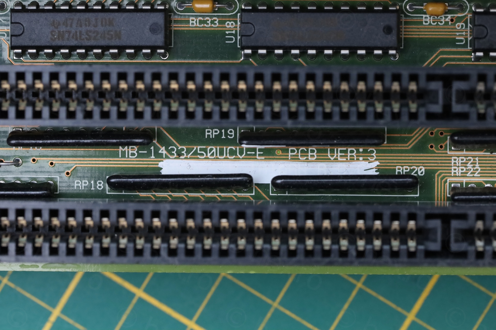
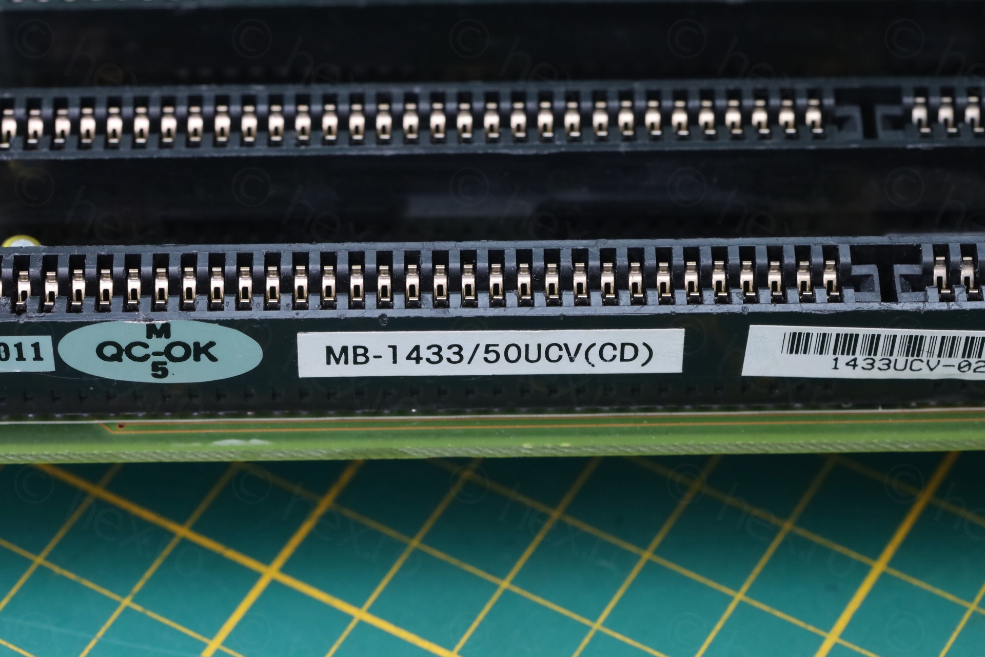
There is a silkscreen text identifying the motherboard as MB-1433/50UCV-E VER:3. However, a sticker on the last ISA socket says CD and not -E: MB-1433/50UCV(CD).
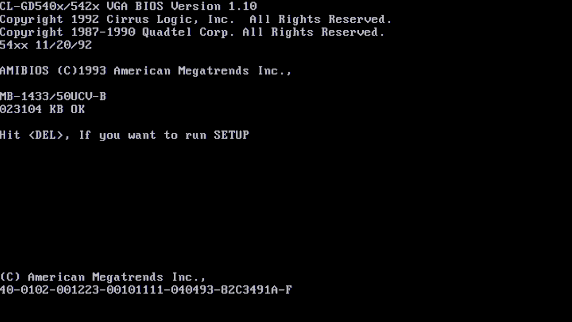
And finally, BIOS reports motherboard as MB-1433/50UCV-B:
I would like to know if this is the original BIOS chip ?
Download here the BIOS of this board (which I saved using nssi). I named it after the real board name, not by what it reports:
biostar_bios_mb-1433-50ucv-e_pcb_ver_3.bin
Phil’s Computer Lab webpage shows a similar MB-1433 motherboard, but with a black IC for BIOS and a slightly different BIOS (although the file name indicates “-D”, I cannot find the “-D” in the binary file, but a “-C”).
In conclusion, an interesting board. I appreciate that the external battery connector is not so close to the ISA slot, allowing me to have both an ISA card as well as the Dupont connector (with external battery pack) plugged in. Weirdly, it doesn’t have a clear Wait State jumper, but a combination of JP19 / JP20 – designed for Cirrus VGA ver AB, ver AC ?
Leave a Reply