

This page is a continuation of AVR (Atmel) USB Programmer article I wrote a while ago. The programmer was unfinished – only USB connection was tested – but it did not do any programming. So make sure you read that part too, otherwise this might seem a bit confusing.
So here we go. I’ve decided to try and program an AT90s2313 which was lying around doing nothing usefull. However, starting where we left, there are more things to check / download / do, before actual programming.
1. Is USB Tiny ISP USB Driver installed and running ?
2. Do I have avrdude 5.5 and an ATMEL compiler ?
3. Do I have the manuals for the uC we’re going to burn ?
4. Do I have a program to burn it to just test the programmer ?
1. USB Driver
By reading the good docs at USBTinyISP, I decided to go with the 1.10 driver. I followed the steps described here and I got myself a working driver!

Windows XP Driver Window
One thing was tricky, but I figured this out after I tried to make avrdude 5.5 work with this driver. When you unpack the driver archive, you have 3 files: libusb0.dll, libusb0.sys and usbtiny.inf. The thing is that WinAVR (version: WinAVR-20080610 ) comes with an older set of libusb0 libs and thus, they are incompatible with the current driver.
Because I initially got my schematics a bit wrong, I thought the issues were probably related to these libraries. So I ended up uninstalling the driver, replacing the driver’s .dll and .sys file with the ones which are in c:\WinAVR-20080610\utils\libusb\bin\ and then reinstalling it. Don’t know if this would work by default or not, right now the USBTinyISP is running with the libusb0.dll / sys which were taken from the WinAVR directory.
Update: After finishing the programmer, I worked with it on a laptop – hence, I had to install the drivers there too. Now I knew the schematic is OK, but the drivers did not work. I just took the 1.10 version, replaces the libusb0.* files with those from WinAVR, and it works. I think driver version 1.12 already includes these files.
2. WinAVR Jun 10 2008 version / avrdude 5.5
As stated on the USBTinyISP site, you need at least avrdude 5.5 to be able to use the programmer, unless you really want some headake on patching older avrdudes. Also, avrdude comes in source code only, and I didn’t really fancied spending hours trying to compile it under Windows. So far so good. By wondering around, I found out that WinAVR already comes with avrdude 5.5 precompiled! Hooray.
Grabed a copy from Sourceforge, installed in in the default directory, and I was set to go.
3. Manuals
RTFM is always a must, and none the less for the AT90s2313 I was going to program. After a lot of frustration with this error:
avrdude: Using SCK period of 10 usec
avrdude: initialization failed, rc=-1
Double check connections and try again, or use -F to override
this check.
I was reading with a last hope the AT90s2313 manual (Serial Programming part); I noticed that it said to pull the RESET pin to GND when doing the programming. Duhh.. After I pulled the pin to GND, everything magically started to work. Hoooray again!
4. Putting everything together.
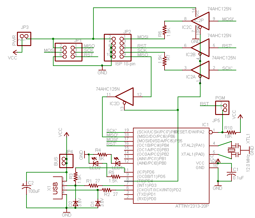
First thing first: the schematic. As the starting point I used this schematic (version 2.0) on the USBTinyISP page. Please also remember that my schematic did not use the Zenner diodes as voltage regulators, but a series of 2 simple diodes to drop the voltage from 5V to around 3.7V.
(right click -> View Image, for the full resolution).

Schematic
You can ignore the UC2’s diode between PB1 and PB2, it’s just for testing purposes – you’ll see below. Also, do not forget to hook UC2 to Vcc and GND properly, but to the 5V provided by the USB.
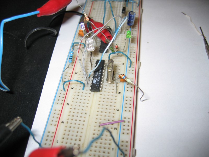
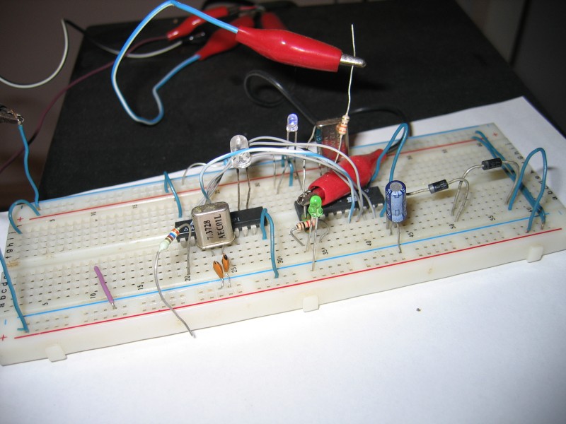
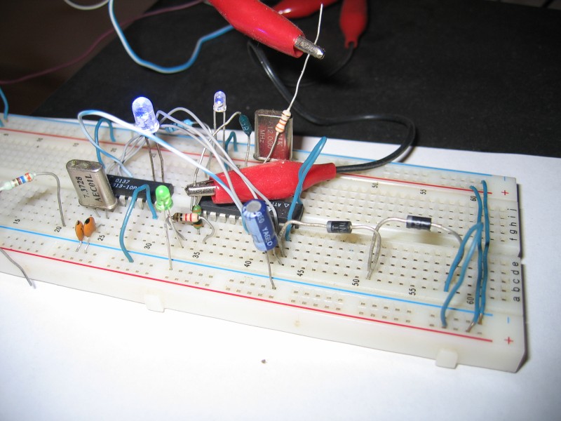
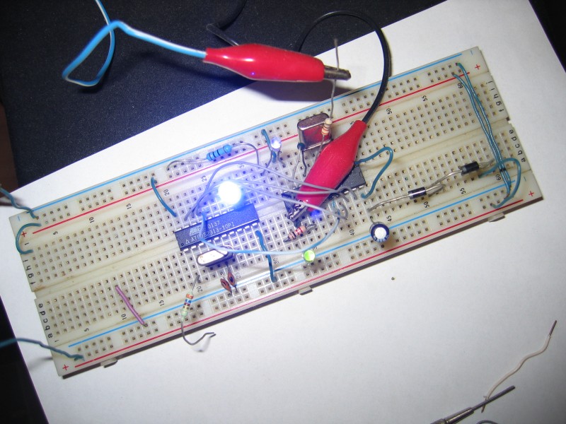
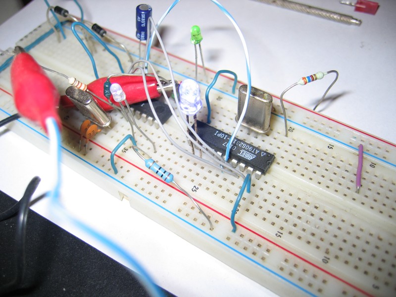
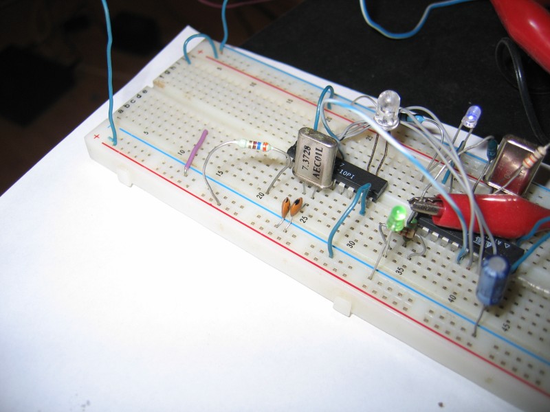
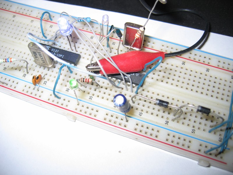
Here’s how my protoboard looks like (again, right click -> View Image for hires pics).
To veriy that the connection works (and that avrdude can see the chip about to be programmed), you can use the command:
avrdude -c usbtiny -p t2313 -U flash:v:
If you get an error such as this one:
avrdude: Error: Could not find USBtiny device (0x1781/0xc9f)
it means that something is wrong with the USB communication. Double check that everything is wired up properly. If the blue light is on (meaning that the computer sees the programmer), but avrdude says it cannot find it, then the chance is that the libusb0.dll from avrdude conflicts with the libusb0.dll from the USBTinyISP driver. Please check point 1. above.
Also, if the error seems to be:
avrdude: initialization failed, rc=-1
Double check connections and try again, or use -F to override
this check.
then, in my case, the solution was to put the RESET pin of AT90s2313 (which I was going to program) to GND.
If everything is well, you should see something like:
C:\WinAVR-20080610\projects\ledb>avrdude -c usbtiny -p 2313 -U flash:v:
avrdude: AVR device initialized and ready to accept instructions
Reading | ################################################## | 100% 0.00s
avrdude: Device signature = 0x1e9101
avrdude: verifying flash memory against :
avrdude: load data flash data from input file :
avrdude: error opening : No such file or directory
avrdude: input file auto detected as invalid format
avrdude: can't open input file : No such file or directory
avrdude: read from file '' failed avrdude done.

Thank you.
I now needed something to make the test led blink but I didn’t feel brave enough to do a blinking led program myself. So I googled around and come up with this document: http://www.ai.uga.edu/mc/microcontrollers/avr/AVRnotebook.pdf
As I was already using WinAVR, I decided to use this piece of code contained in the book:
/* Blinking LEDs in AVR-GCC */
#include
#define F_CPU 7372800
#include
int main()
{
 DDRB  = 0b00000011;
 PORTB = 0b00000010;
 while (1)
 {
  PORTB ^= 0b00000011;
  _delay_loop_2(50000);
  _delay_loop_2(50000);
  _delay_loop_2(50000);
 }
}
I just had to adjust the F_CPU variable to match my quartz speed, and save this file as ledb.c in some folder on disk.
However, to compile it, I needed a Makefile to make it work. This is the Makefile I’m using (you will probably need to add the WinAVR bin’s directory to the path before compiling). Also, if you look closely, you’ll see that it does include the ‘write’ rule which burns the flash:
# write to cpu
write:
avrdude -c usbtiny -p 2313 -F -v -e -U flash:w:ledb.hex
So, after about one and a half hours of reading manuals, checking schematic, checking forums for the errors I got, etc, I was finally able to achieve success!
avrdude: Using SCK period of 10 usec
avrdude: AVR device initialized and ready to accept instructions

Reading | ################################################## | 100% 0.02s

avrdude: Device signature = 0x1e9101
avrdude: safemode: Fuse reading not support by programmer.
Safemode disabled.
avrdude: erasing chip
avrdude: Using SCK period of 10 usec
avrdude: reading input file "ledb.hex"
avrdude: input file ledb.hex auto detected as Intel Hex
avrdude: writing flash (126 bytes):

Writing | ################################################## | 100% 1.50s

avrdude: 126 bytes of flash written
avrdude: verifying flash memory against ledb.hex:
avrdude: load data flash data from input file ledb.hex:
avrdude: input file ledb.hex auto detected as Intel Hex
avrdude: input file ledb.hex contains 126 bytes
avrdude: reading on-chip flash data:

Reading | ################################################## | 100% 0.52s

avrdude: verifying ...
avrdude: 126 bytes of flash verified

avrdude done.  Thank you.
Also, a sweet thing about USBTinyISP is the green led which lights up when it’s actually burning (or just communicating) with the chip. Here’s a small youtube video showing the burning phase (green led turns on for a couple of seconds) and then I just disconnect the RESET pin from GND:
[youtube]http://www.youtube.com/v/z8j4N2ZtNxg[/youtube]
Conclusion: I hope this tutorial helps 🙂 if you have questions, please feel free to ask on the forum.
USBTinyISP rules!
WARNING – Older Atmel controllers (AT90s1200 / AT90s2313) are not really supported anymore (you might brick them). Please see LadyAda’s answer from here. Hence, the warning below does not apply anymore – I presumed the schematic does not work because of the low power. However, it was due to the fact that controllers are not supported anymore (but I’m not clear if they aren’t supported by avrdude / usbtinyisp / or if they fail due to the low power mode – etc). Schematic works perfect with newer controllers even if using laptop’s USB; I’ve tested it afterward with ATTiny2313.
WARNING: As I posted on LadyAda’s forums here , I have some reasons to believe that powering this schematic from USB on a laptop might brick some controllers. While building it and afterward using this programmer on my desktop PC, all was sweet and without problems. After moving to the laptop (USB port does not provide as much power as the desktop one), after being written just for 1 time, 3 uC started behaving strangely.
Please make sure you connect the ‘about to be programmed’ chip to USB’s VCC, and only let the programming chip (ATTiny2313) to ~3.7V.
Leave a Reply