
This page is about a small modification I did to USBTinyISP schematic (give up the zenner diodes) which I did not have when I wanted to build the programmer myself. Here goes…
If you are like me, then, from time to time, you get an AVR itch that just needs some scratching ![]()
Last time for me was 5 years ago when I programmed an Winamp Light Chaser (some video demos of that you can find in this page, please scroll at the bottom where it says ‘Filme’, there are 4 of them divx encoded.)
I do still have an LPT port available, but I’m about to sell the computer and I had no LPT ports remaining for Atmel programming via SPI. So I started looking up for USB alternatives. There seem to be a few resources out there, however, now, at the time of writting, the most successfull one is USBTinyISP which just got a hefty boost by being supported by avrdude starting version 5.5. Very nice!
Basically, all work on this page is based on USBTinyISP firmware version 2.0. The changes I did to the schematic, I did them to use the fewest possible parts and to avoid the Zener diodes.
Support for USBTinyISP is great, I got answers Saturday evening! I asked for confirmation that everything will run at 3.6V too. Now now that I’m thinking of, it would have been better to buy this programmer, instead of spending my whole Sunday to make it work. Anyway…
First, some theory:
a) Communicating with USB is more difficult than communicating with RS232. You can either use an USB to RS232 converter (such as FT232), but these converters are available only in SMD packaging plus they are difficult to work with. The other alternative is to attempt to handle all the wave forms encoding/CRCs software only using a separate microcontroller which will also flash the uC you intend to flash. Having a separate uC is difficult (the programming part) but not impossible (in fact, USBTinyISP is based on the work done by AVR-USB). And you also need a working programmer to program the ‘middle man’ uC (which is an ATtiny2313).
b) You’ll need a Windows driver if you intend to use this on Windows (driver is available for free at USBTinyISP site, including exact explanations on which one to use). Make sure you read the whole page to see exactly what version to use.
c) USB does provide 5V on its VCC line, however, the data lines (D+ / D-) expect maximum 3.6V. You can either use a level shifter (such as a 3.6V Zener diode) only on the data lines, or you can power the whole programmer at ~3.6V and give up the Zener diodes. You can read more if you visit this page (it’s in fact where I took the informations myself).
Low powering the device is possible because AVRs work at this voltage, but you cannot use the programmer to do any ISP, because probably the board you intend to program is already at 5V and you’ll have a conflict. As I only wanted a SPI programmer, I decided to give up on the Zener diodes, and go for the 3.6V power (plus, on Sunday when I got time to work on this, I had no 3.6V zener diodes at hand).
d) One more think I did not know, and this took me hours to figure it out how to do it correctly, is that ATtiny2313 is special, compared with its older AT90s2313 which I was familiar with.
- It comes with an internal oscillator, so, by default, it doesn’t use the external quartz/crystal. Duh.
- It comes with fuses which you can burn (write in fact) and this is the way you configure it to use the external crystal. Most of the programmers (you need one in fact to burn the ATtiny2313) are able to write these fuses.
The Makefiles / docs, in USBTinyISP do mention the fuses values (the correct ones). The thing is that they do not insist in using those fuse values, and I, after reading a couple of other web pages about the recomanded fuse values, etc, I ended up pretty confused on which ones are the correct ones.
The reason why it’s important to properly fuse the ATtiny2313 is that the exact 12.000Mhz (no more, no less) exteral quarts is actually needed to handle USB communication. You have to burn those fuses with value 1111 for CKSEL3..0 and 10 for SUT1..0 to enable external crystal + fast start up time. Otherwise you’ll end up with “USB Device Not Recognised” (in Windows) or “device descriptor read/64, error -71” (in Linux).
So these things being said, I’ve used this schematic instead for the USB communication part (exact same source code from USBTinyISP is working, and of course, you have to get there to get it. Make sure you read about which driver to use in Windows, at the moment of writing the recomanded one was v1.10):
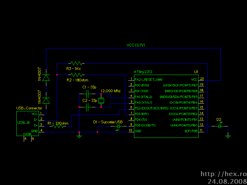
Figure 1.
Also, please notice that the schematic is incomplete, and I haven’t yet added the programming part (SPI pins). However, USB communication works, and I was able to install the Windows driver.
I gave up the resistors which were in series with the LEDs. As far as I remember from AT90s2313, these chips already had an internal resistor which was activated when a pin was set as output.
I also gave up the Zener diodes, by powering the circuit at VCC = VCC (USB) – 2 x Voltage drop on each 1N4007 diode (~0.65V each) = ~3.7V. A 4.7uF capacitor is needed though (which is not yet in the schematic, but I’ll add it) between this 3.7V Vcc and GND. Not critical, but when a small power glitch happen (such as when air conditioning external unit starts), the device might be disconnected.
Below are more pictures including explanations:
I didn’t have any USB connector at hands, so I decided to use an USB cable.
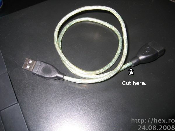
Figure 2.
USB Pinout (read more about it here)
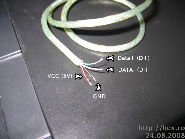
Figure 3.
To be able to low power the uC at ~3.7V, I’ve used two diodes in series. Each diode has avout 0.65V across it, and if you add two, this means 5V – 2*0.65V ~= 3.7V.
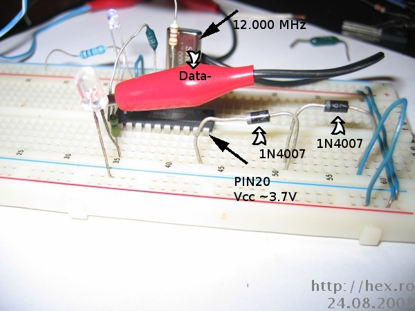
Figure 4.
Top View. As you can see, USB connection is on, the smaller blue led (which in the original USBTinyISP was the green one) is turned on.
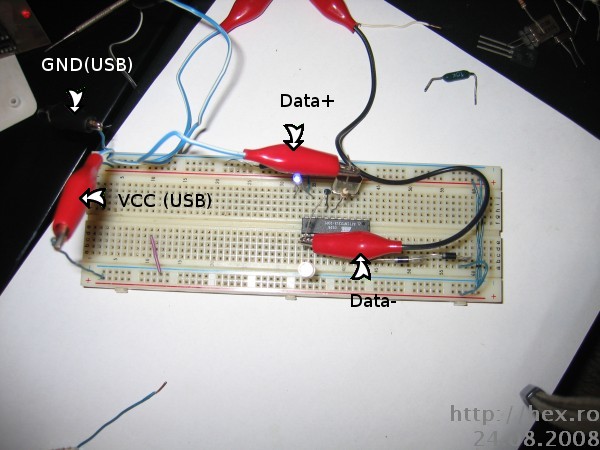
Figure 5.
Front View. Here you can see how R2 and R3 are connected and D- starts where they are united. You do need those two resistors, because D- needs to be pulled up when operating. USBTinyISP schematic has R1 and R2 be 67ohm and R3 = 1k5. I didn’t have those values exact values, so I had to improvise a bit:
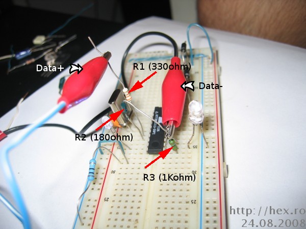 Figure 6.
That’s it so far. I will finish the programmer these days, and post an update.
Good luck 🙂
PS: The update is available.
Leave a Reply