Table of Contents
Introduction
I spotted this EBay listing of an Issue 6a Sinclair Spectrum motherboard. Descriptions were austere: seller accepts no complaints nor returns, Condition was set to “for parts or not working” with a short description of “Does not Power on”.
This was enough to keep some bidders away. Soon after, I had it on my bench.
Overview
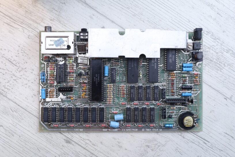
The seller had only few blurry images posted. Large resolution but rather blurry. I did spot that the ULA has was marked with a red marker, the capacitors had different colors, and that a lower RAM chips had a lot of solder on them.
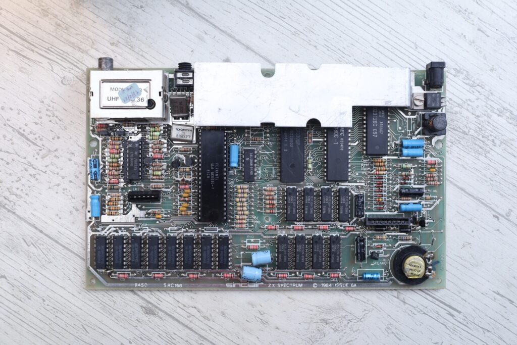
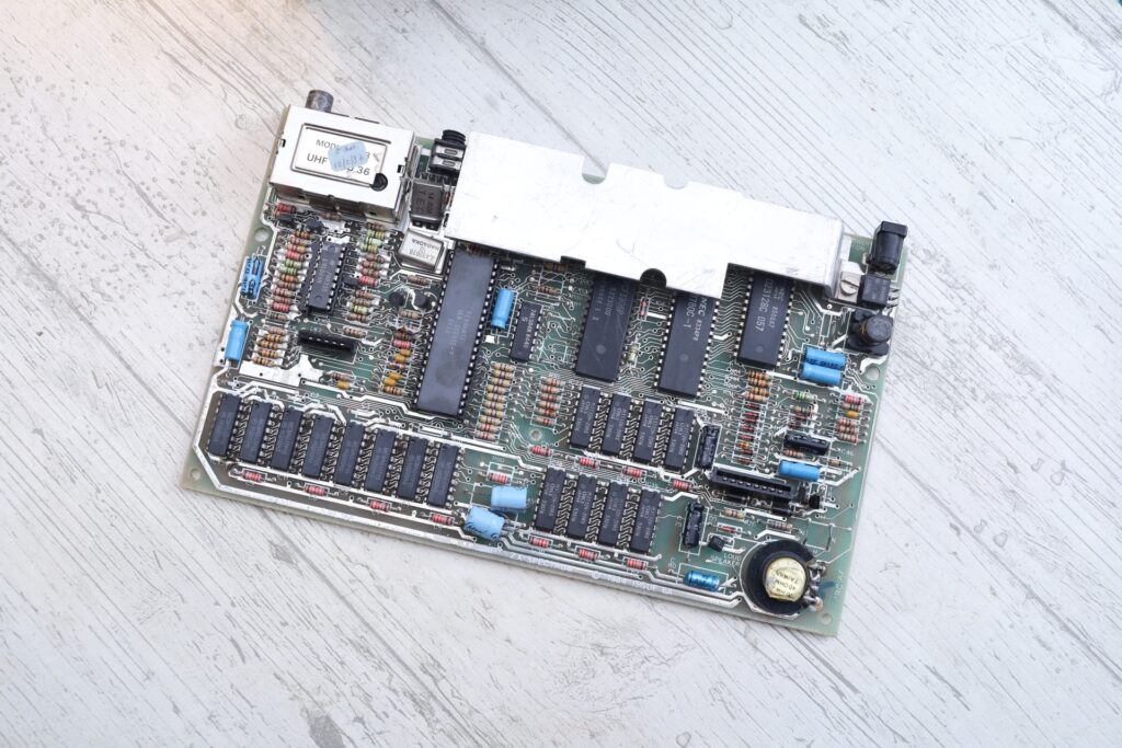
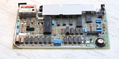
Here are some better photos I took:
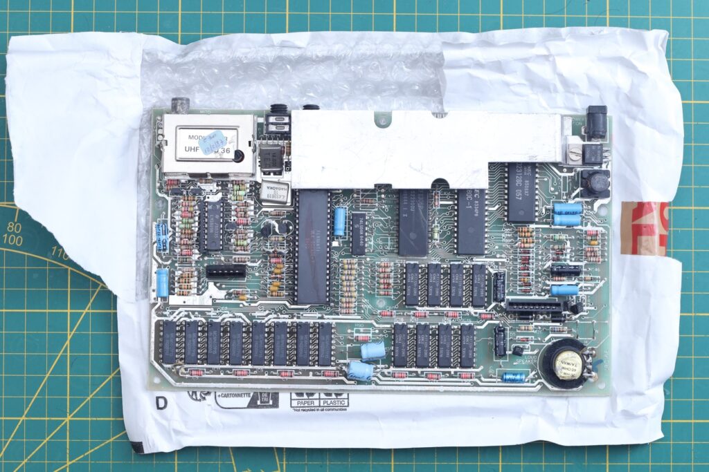

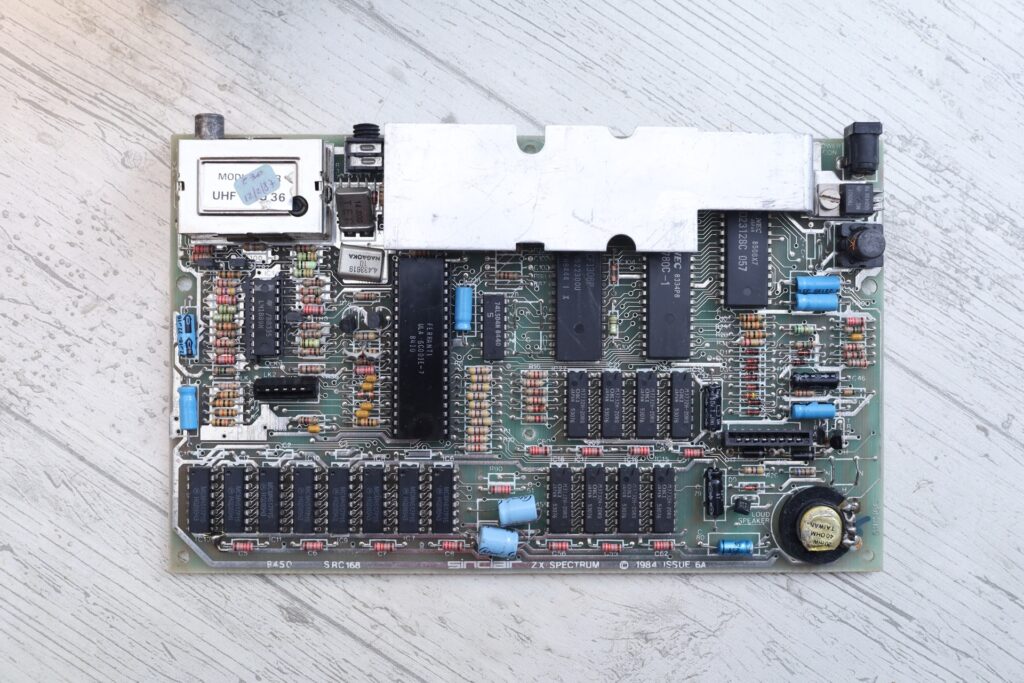
Long story short … the board works. I wanted this to be an article about a repair / diagnostic, but it ended up just a description of what I got.
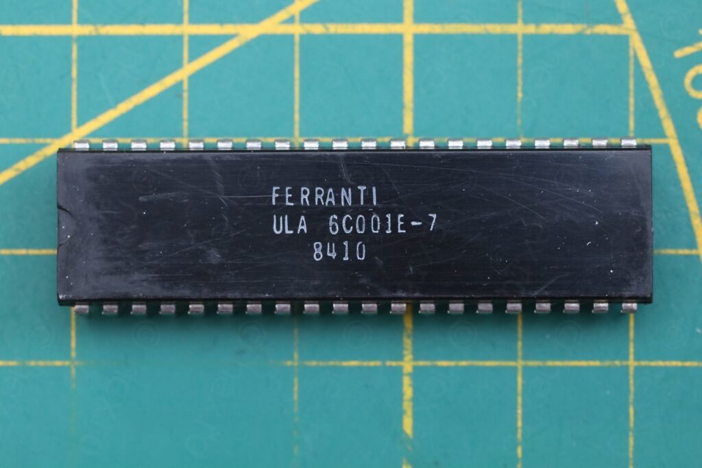
The ULA works but is cracked. Although it stays at low temperatures, I am not convinced about its longevity. The board price was good for spares, better than ordering an original CPU, an original ROM, some other ICs and pay shipping prices for each of those sellers. Thus, a very pleasant surprise that ULA works, but with the bitterness that its plastic body as two transversal cracks.
Thus, below, descriptions below about the repairs I saw on the board. Some of them were puzzling, but hey, board works, so they are fine.
TR4 / TR5
The two transistors TR4 and TR5 are the original ones: TR4 is the ZTX650 and TR5 is the ZTX213. However, there are flux remains under TR4:
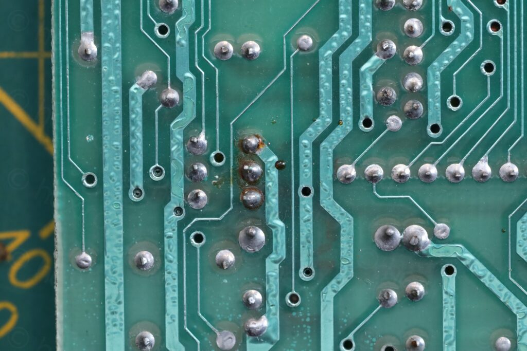
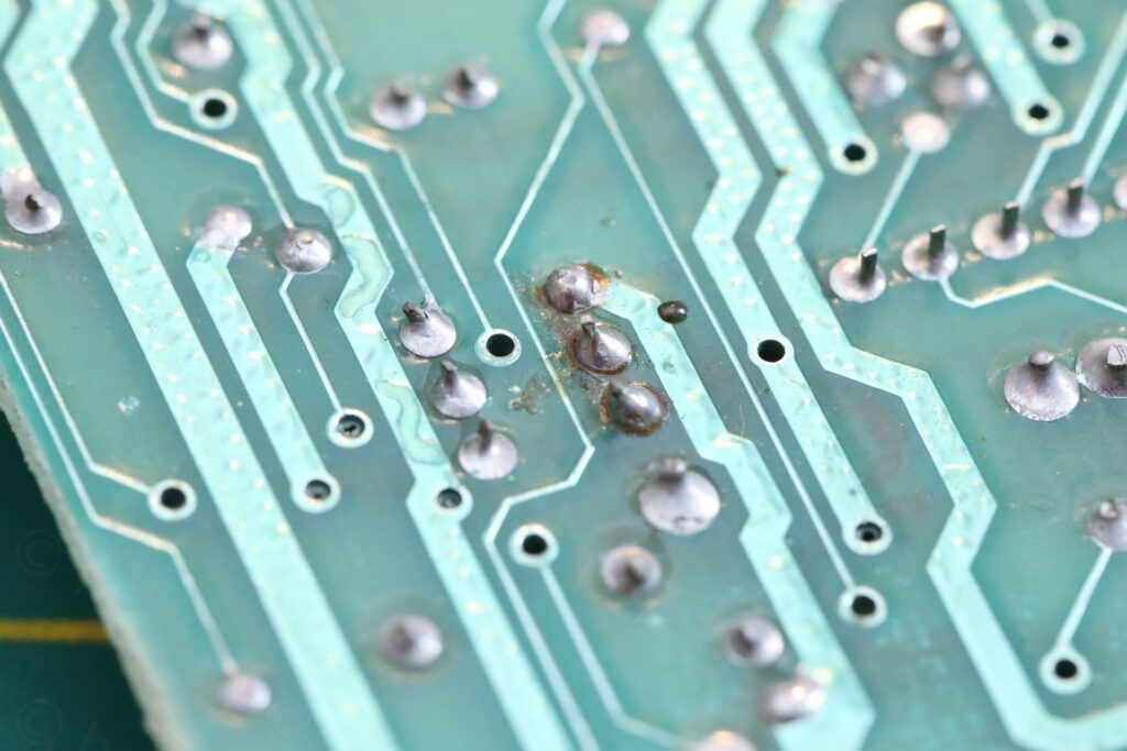
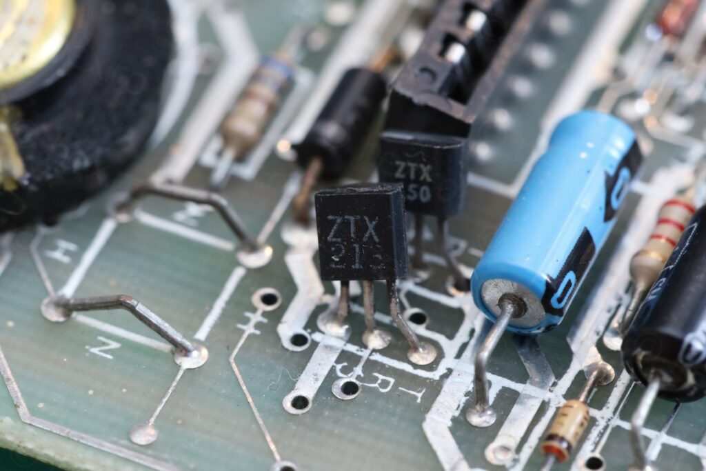
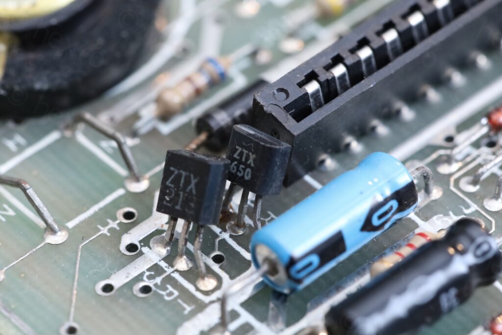
Weird that TR4 was just re-soldered.
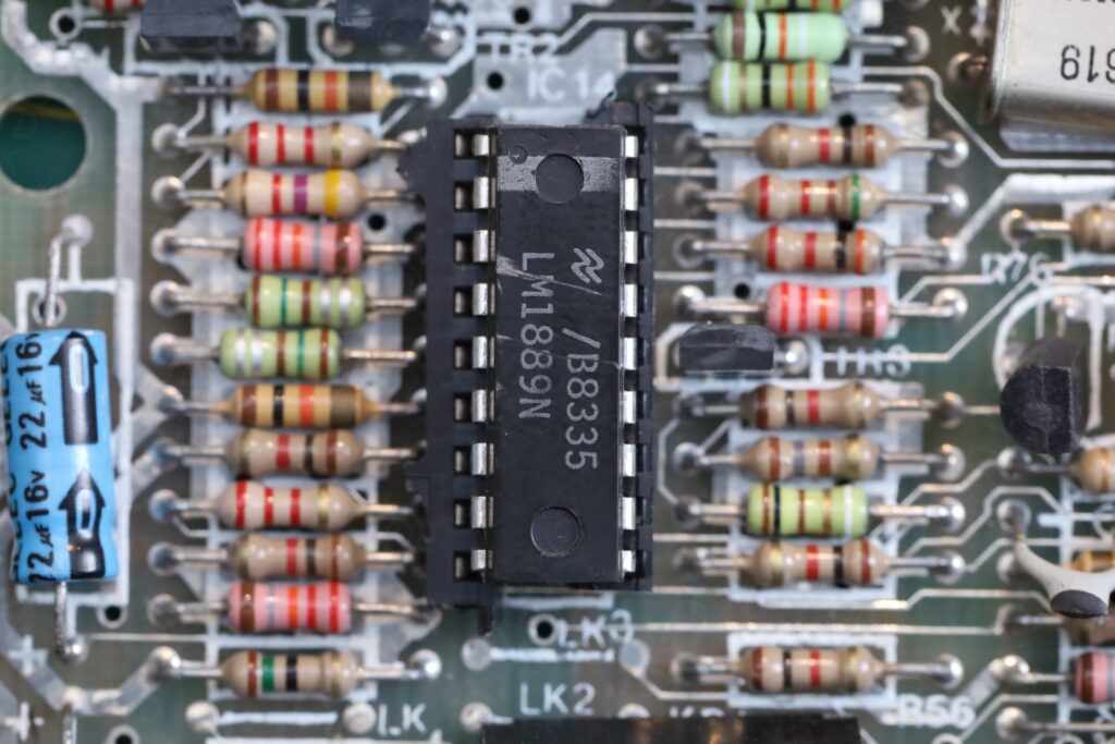
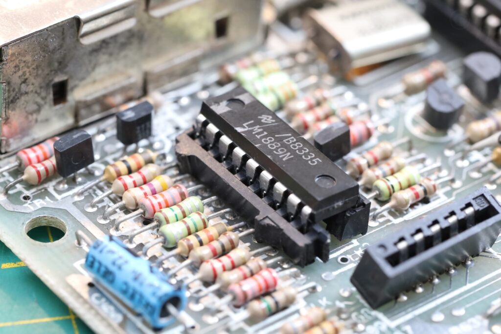
LM1889N – socketed ?
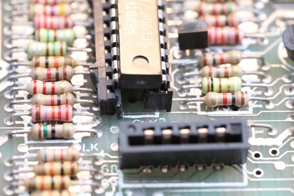
Another surprise was that LM1889N chip is socketed. I didn’t work on so many Sinclair Spectrum boards, but I never saw an LM1889N in a socket.
On closer inspection, the socket is improvised from what appears to be some pin rows torn from a larger socket. The poor IC does not sit horizontal. I really do not understand what went on here.
Capacitors
My attention was drawn to these Chton capacitors. Board is designed for axial capacitors, but somebody installed these radial ones:
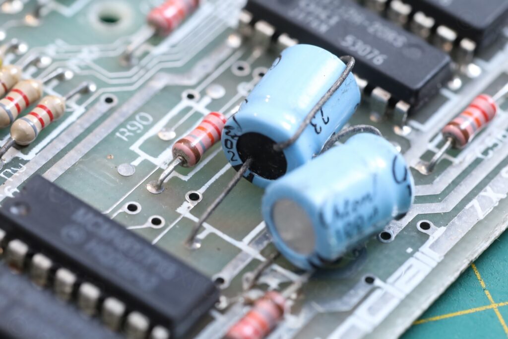
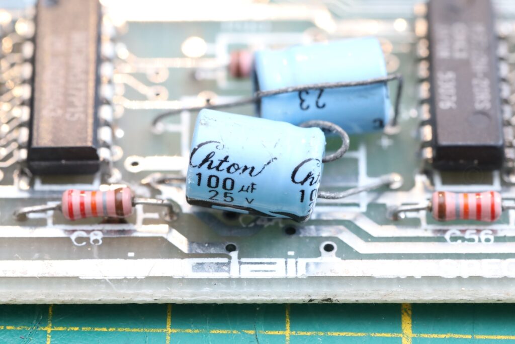
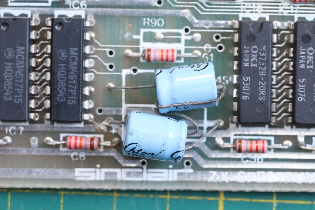
Capacitor do not seem factory (and their leads shows signs of corrosion). They do old too.
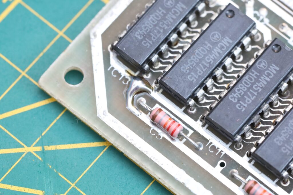
Lower RAM – all replaced ?
Except the large flux remains on the Lower RAM IC pins, there’s also a power track that was cut. Then fixed with a solder blob:
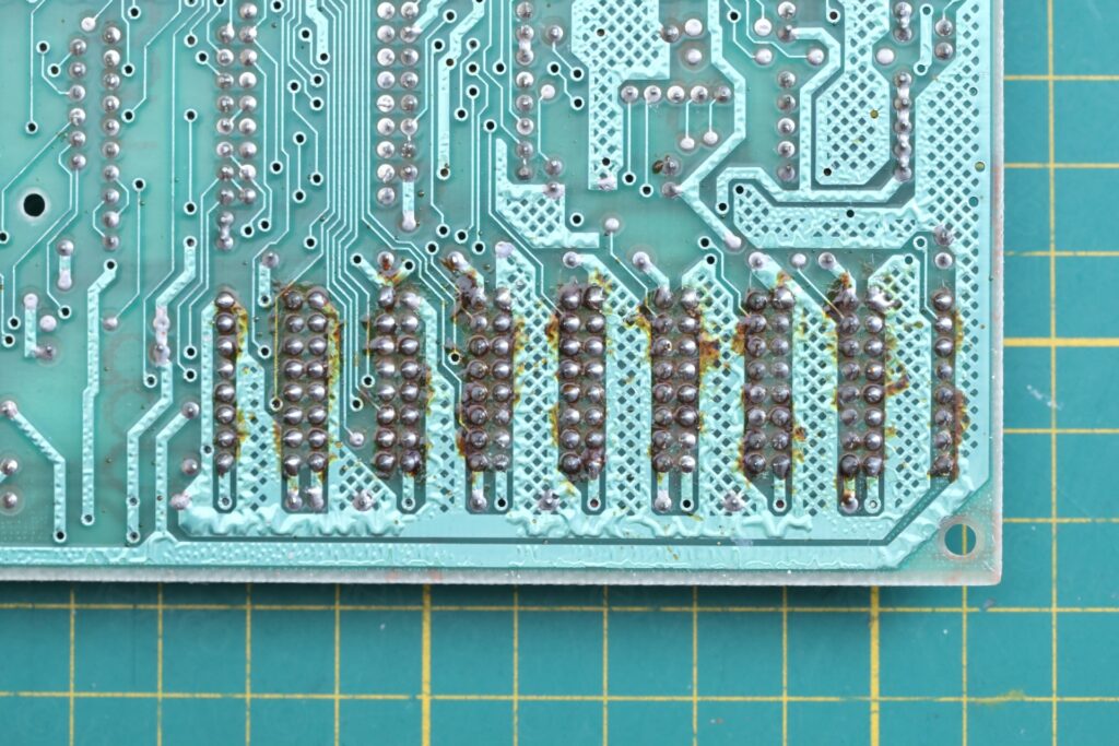
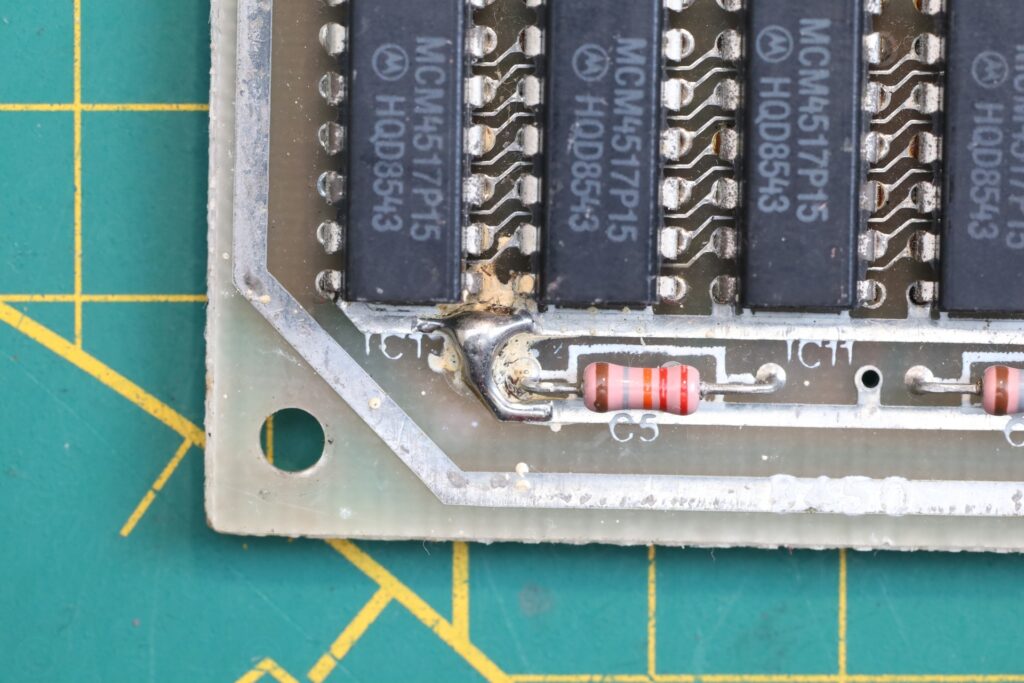
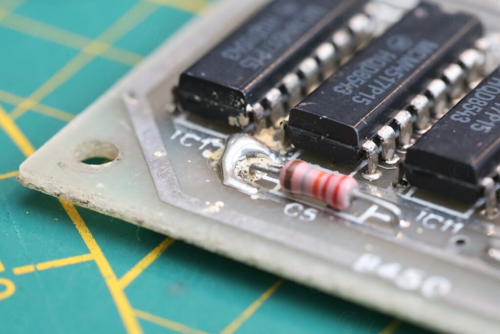
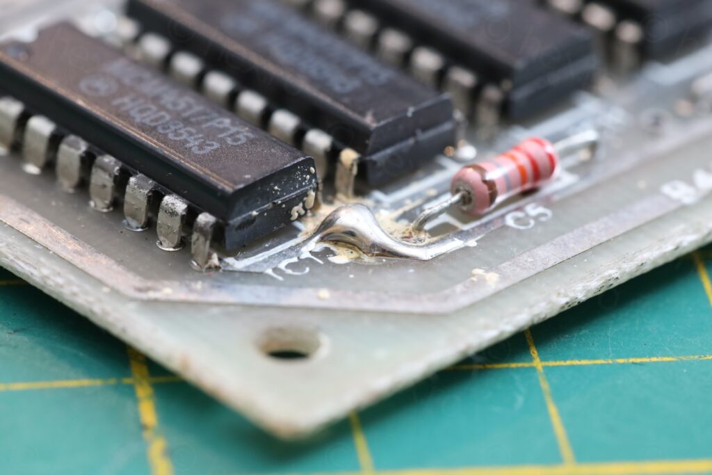
The board is populated with 8 MCM4517P15 Motorola ICs. Sinclair boards usually come populated with 4116 2N memory chips, thus, they look like replacements.
There was also this residue around the solder blob, it cleaned with IPA.
ULA – Cracked
There are two transversal cracks on the top of the ULA:
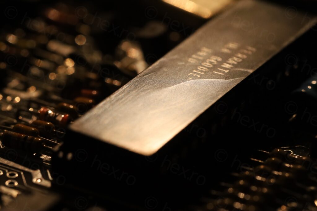
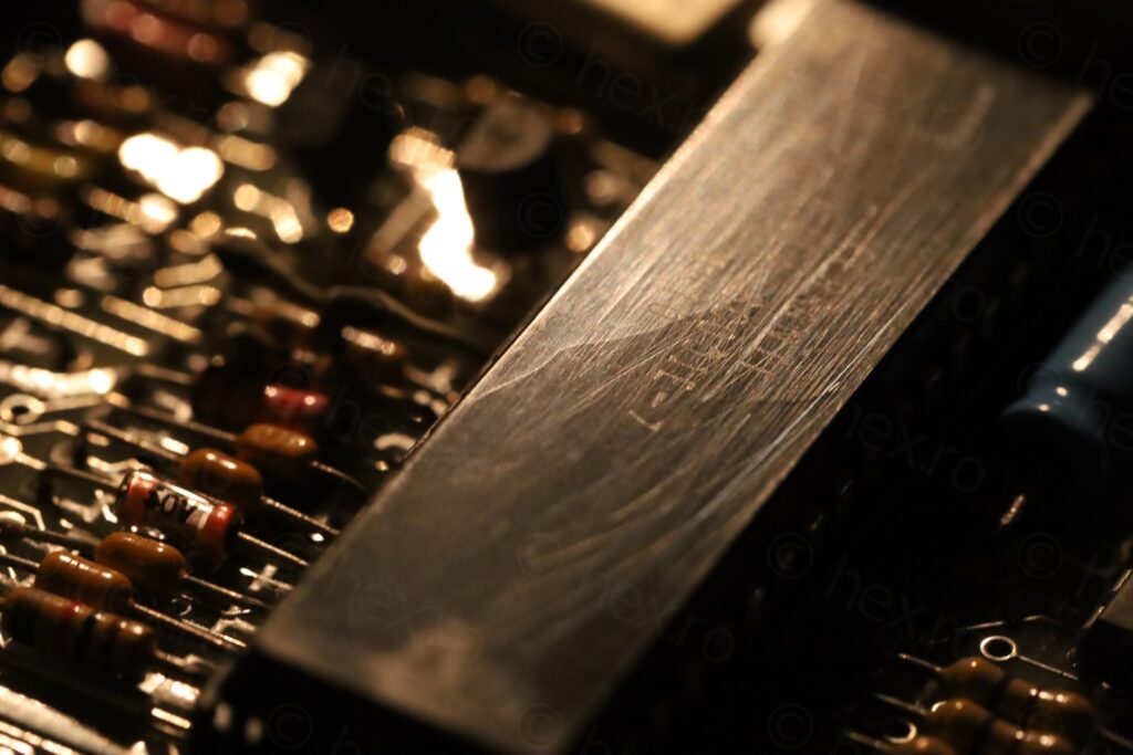
The ULA also has lots of signs of scratches (as if being scrubbed longitudinally with an abrasive material), but the real plastic cracks are transversal. They are obvious as they change the light direction:
I wanted to see the cracks under the microscope and was worried that removing the ULA could make the cracks worse. But if this ULA is now captive to this board, then … is not very useful. So I may as well take it out.
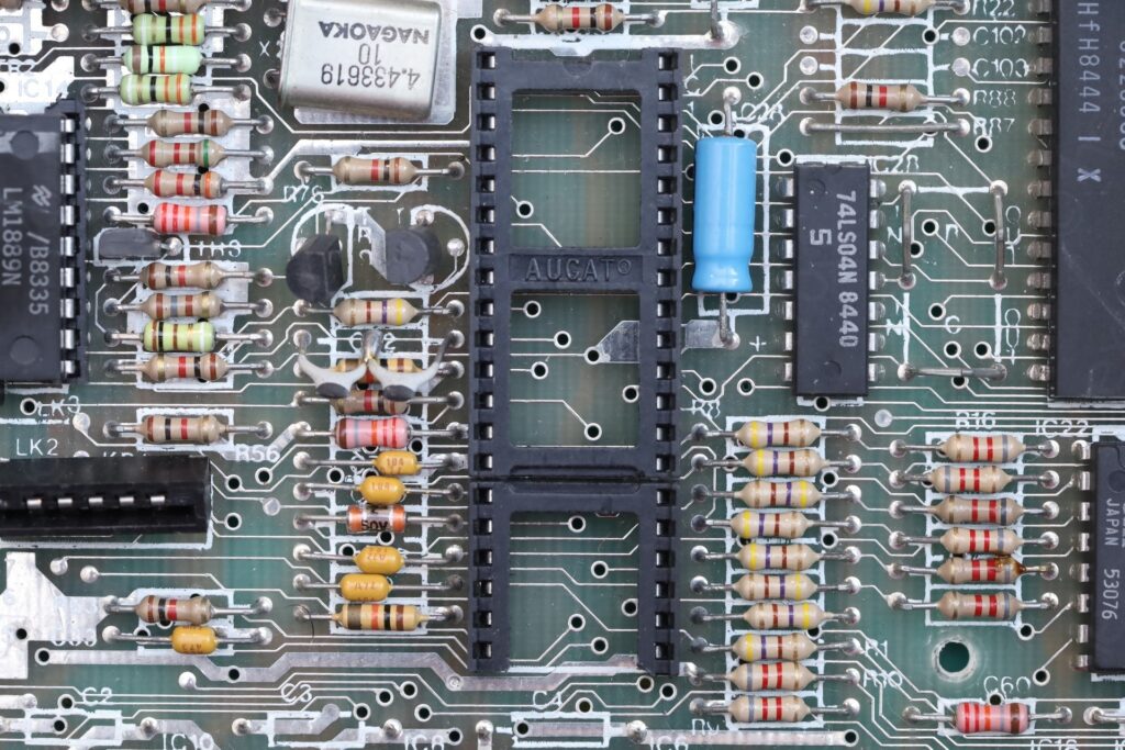
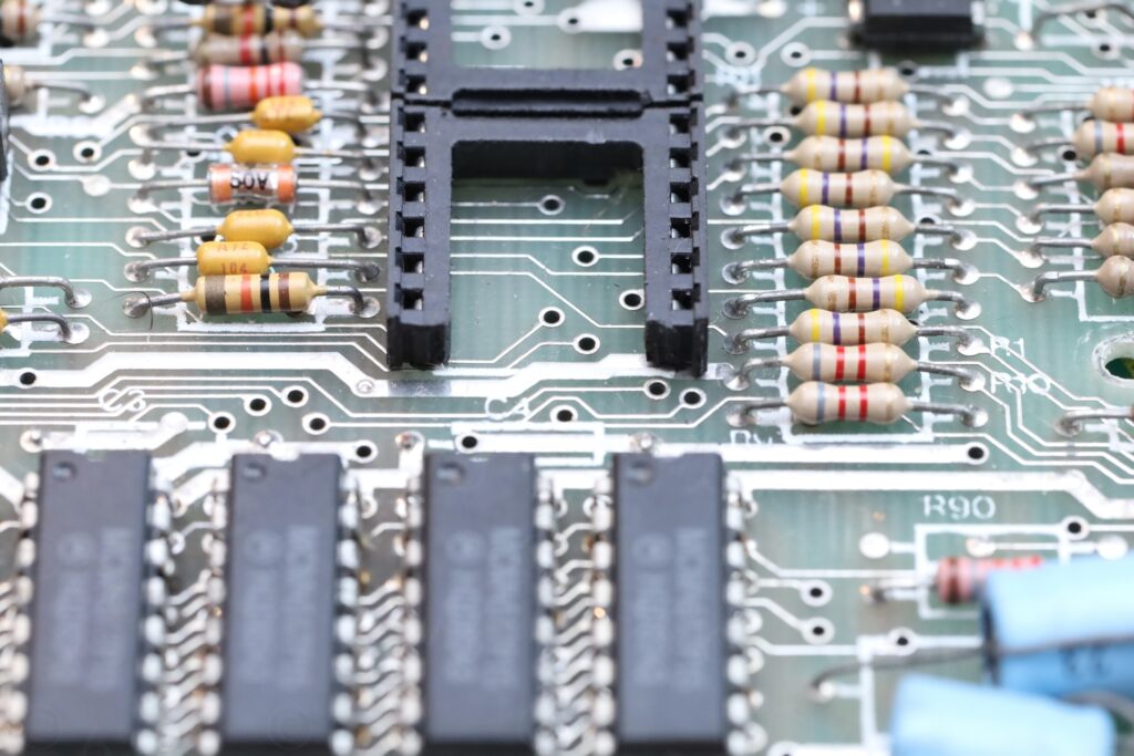
Surprise. its socket also is not factory, but a DIY job – assembled by a shorter sockets, one ‘cut’ to fit:
Anyway, here is video. I don’t remember the magnification I took the video out (was it 200x ?) but what I can see is that the crack is old. There are other scratches that look “newer” (that cross it):
RF Modulator label
Usually the RF Modulators have a flat lid, with a label having a Red (followed by a Black) band on top. This one is seems to be different. Lid is not flat and the word “Astec” is missing, and it consists in “Modulator UHF” and 36 written on a gray label:
Conclusion
This computer had a major repair, but done long time ago. Somebody desoldered TR4, lifted the LM1889 chip and ULA (most likely the ULA socket did not survive that operation, an improvised one is in its place), cut a trace to the lower RAM ICs and decided to just replace the lower RAM ICs. The ULA has also some cracks but it seems that are still tight.
Few more photos below:
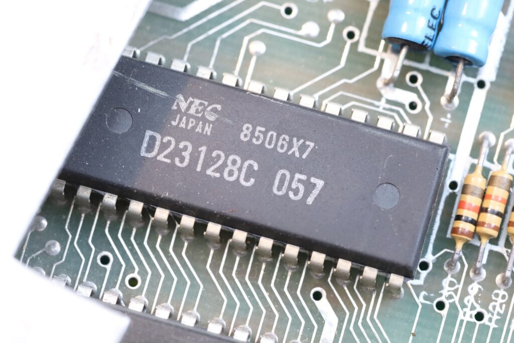
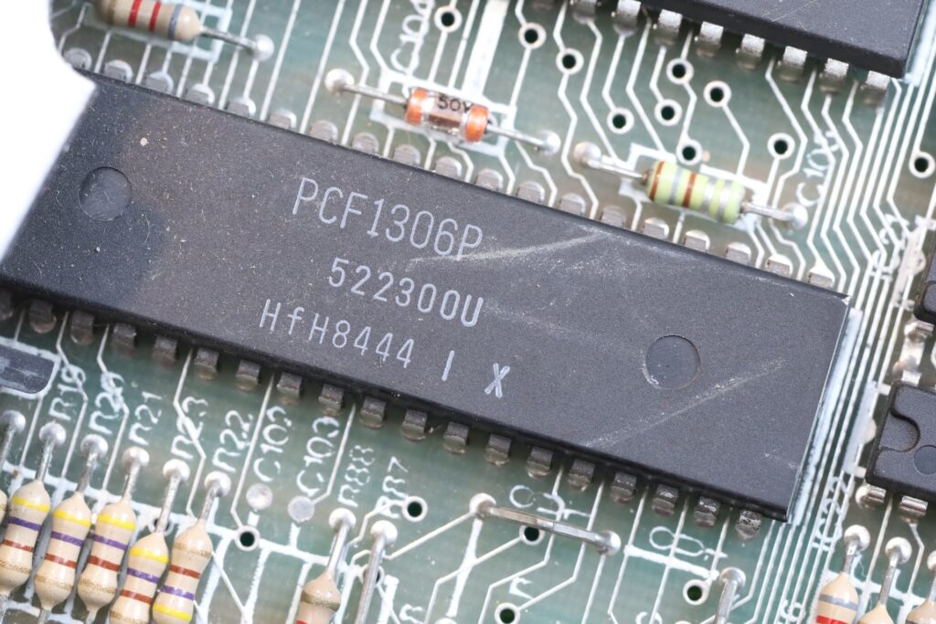
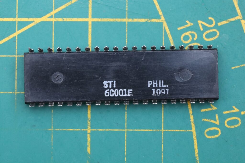
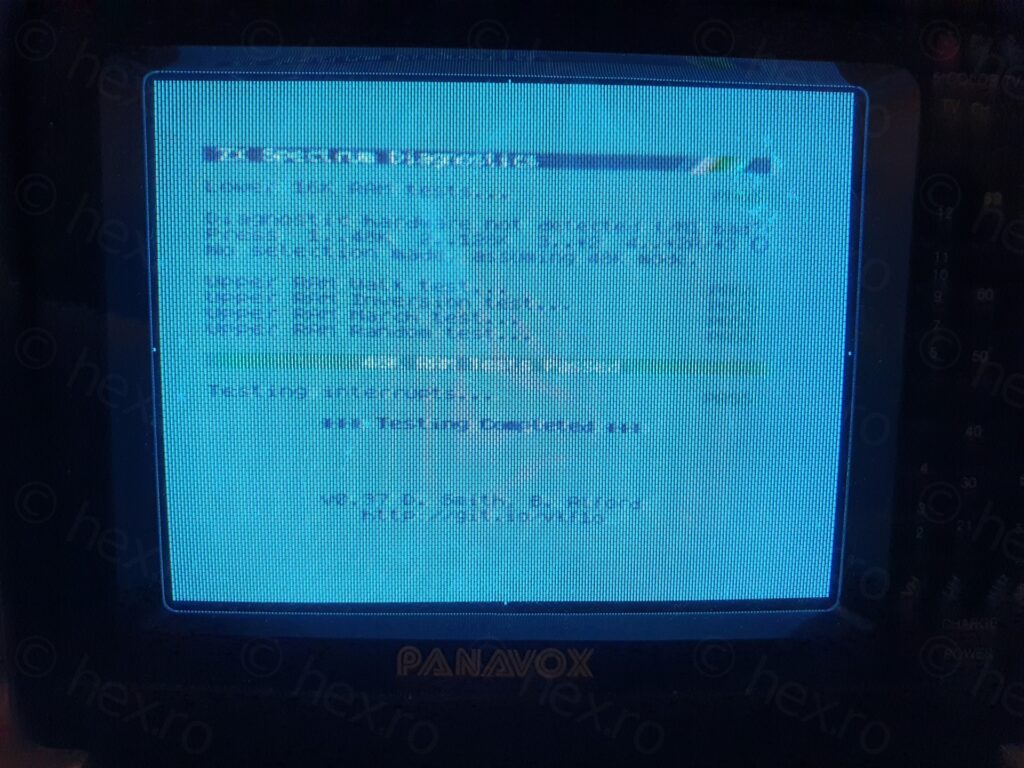
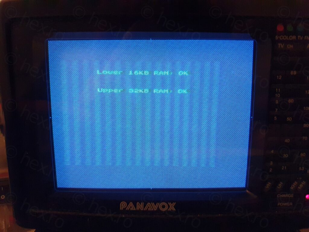
I also have no idea why the seller said it doesn’t work, maybe a cold solder joint or some other issues with his test setup ? Or he absolutely wanted to make sure there is no reason to try to return the board ? I have no idea.
I appreciate the work of the old tech though, he was able to repair the computer and this is the most important. It may be that ULA was cracked during that repair, but it still works.

Leave a Reply