One evening I stumbled on a Sinclair ZX Spectrum motherboard listing on ebay. It was sold as “not working, for parts or spares” with an affordable price. I do have some Sinclair ZX Spectrums that I have bought throughout the years – original box and accessories – but what if something would stop working on them ? Will I know how to fix ?
Thus, decided to embark on a new journey, fixing Sinclair ZX Spectrum motherboards. And it started with this one.
Table of Contents
Evaluation
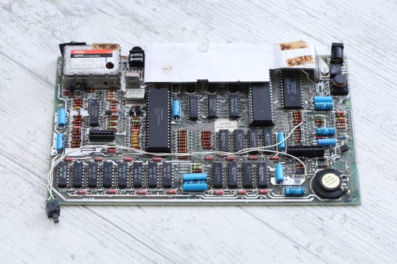
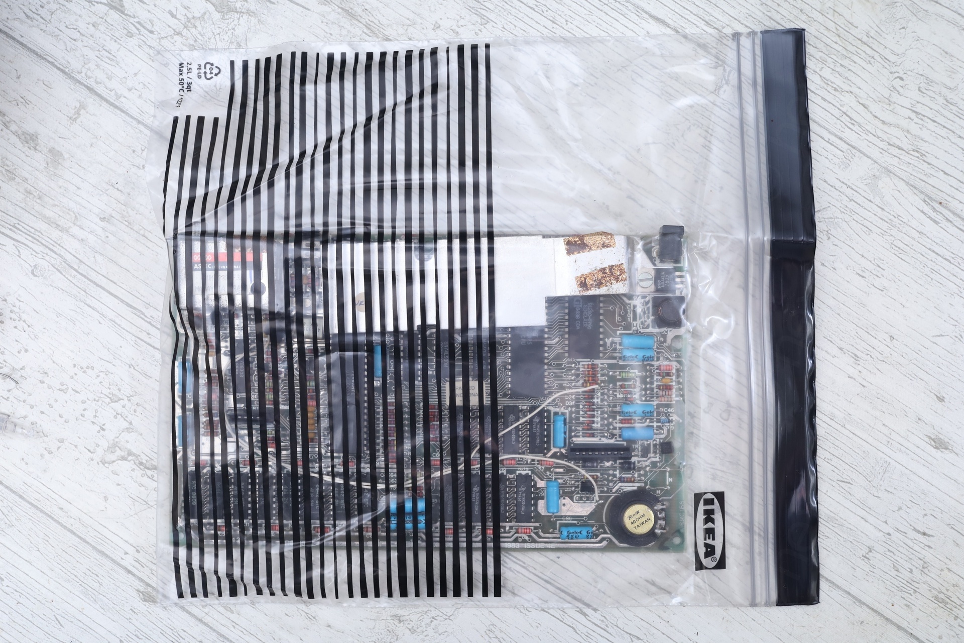
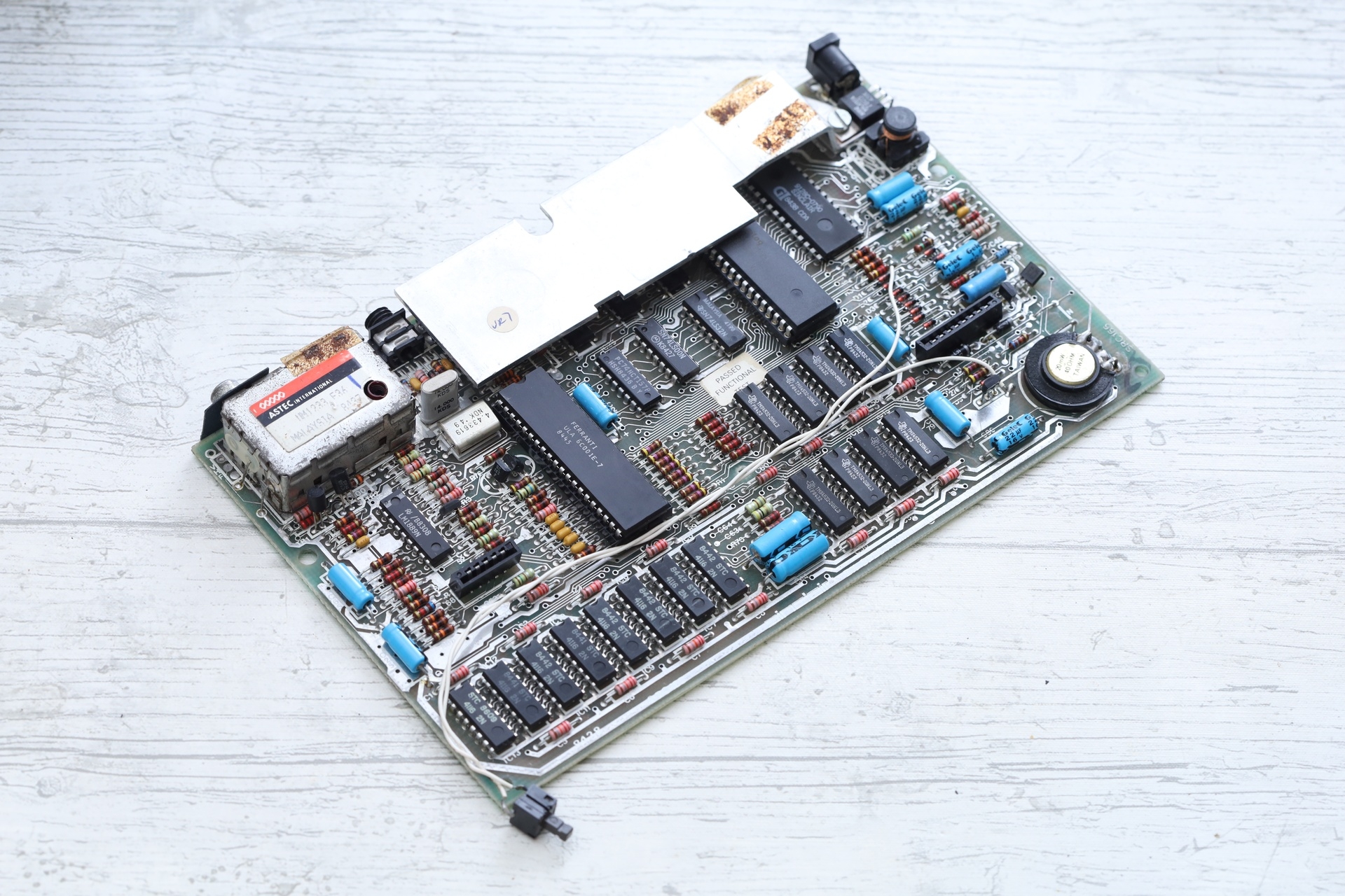
I received the board in a very weird packaging. Although padded in some bubble wrap, it arrived in a Perfume Shop carton bag, the board itself being slipped inside an Ikea resealable bag. I appreciated the reuse 🙂
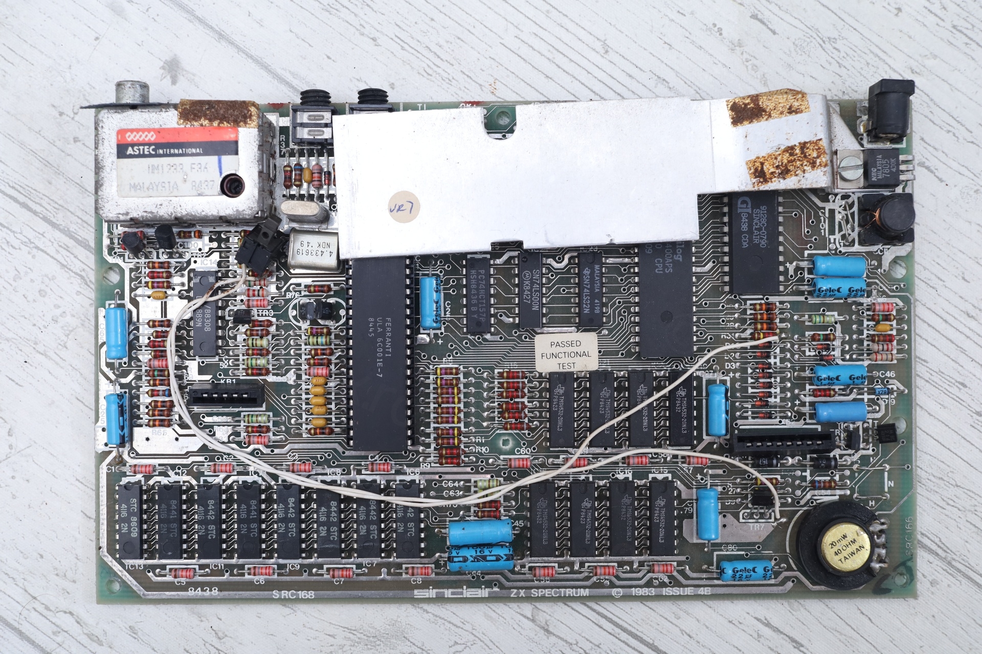
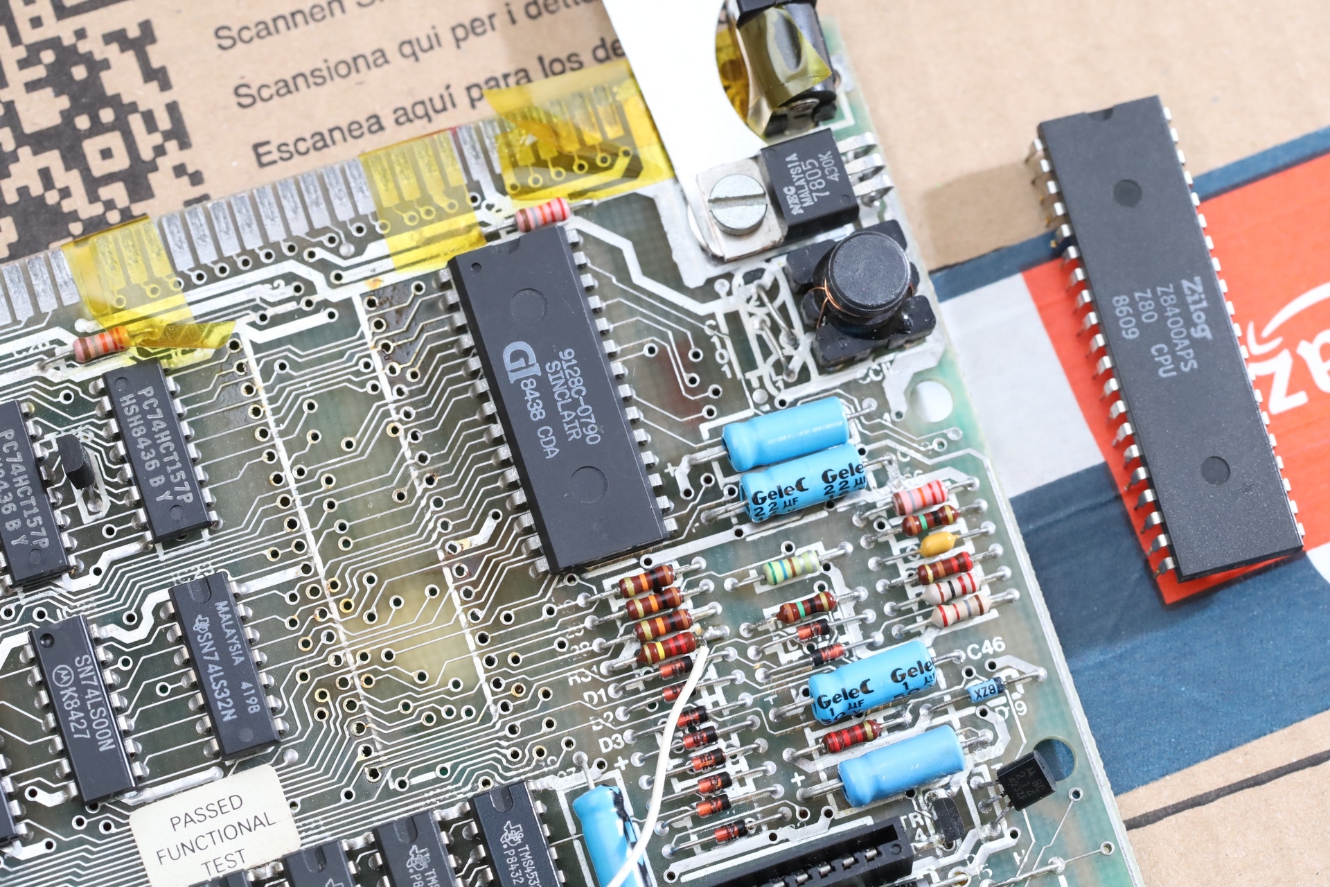
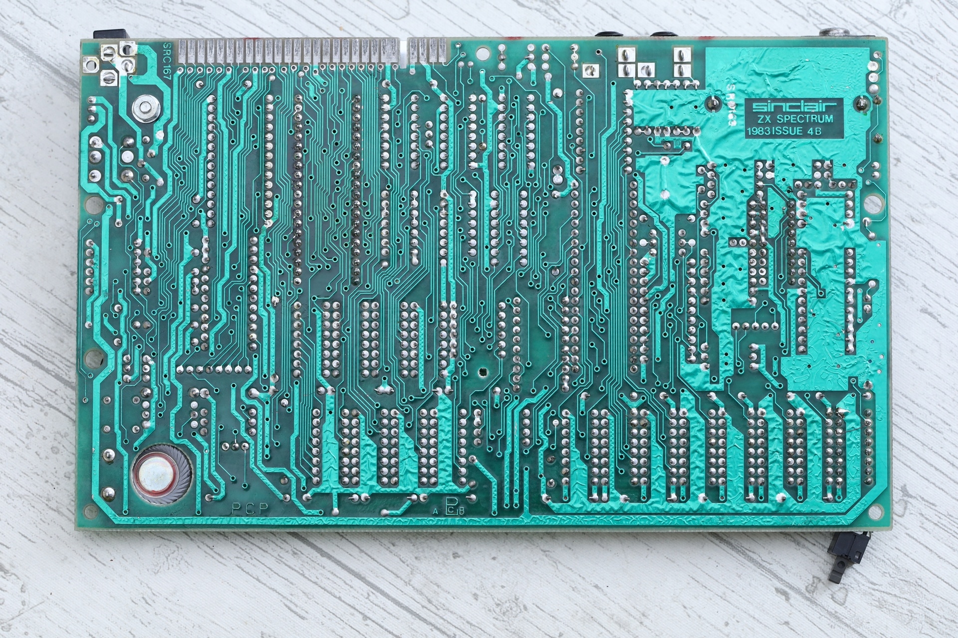
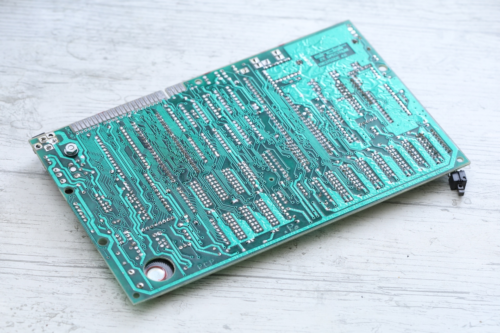
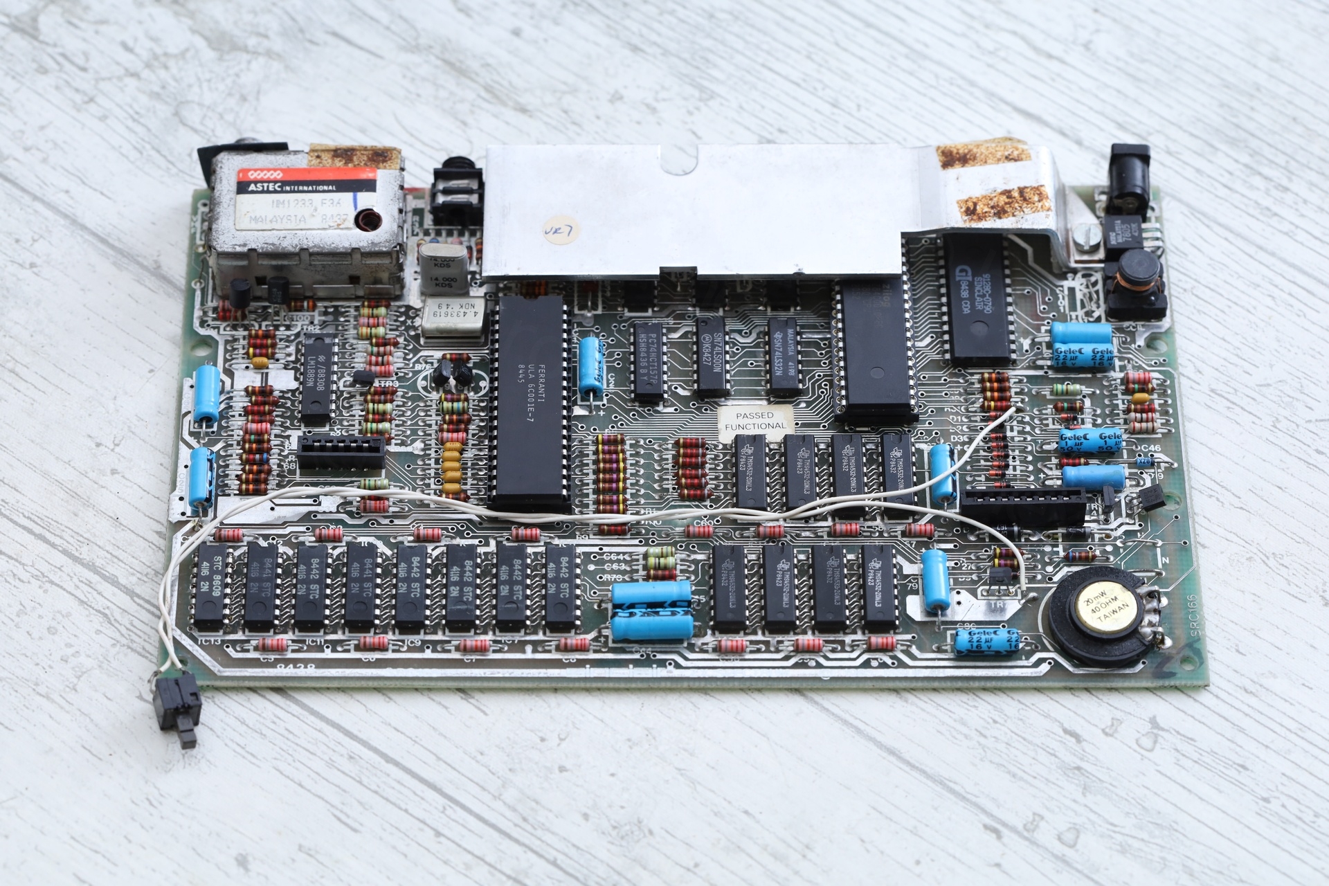
Having a closer look, I discovered that a lot of work has already been done to it. Being already in uncharted territories since it was my first fix attempt and now more uncertainties ? Effort already put in and still doesn’t work ? Oops.
Previous repair attempts
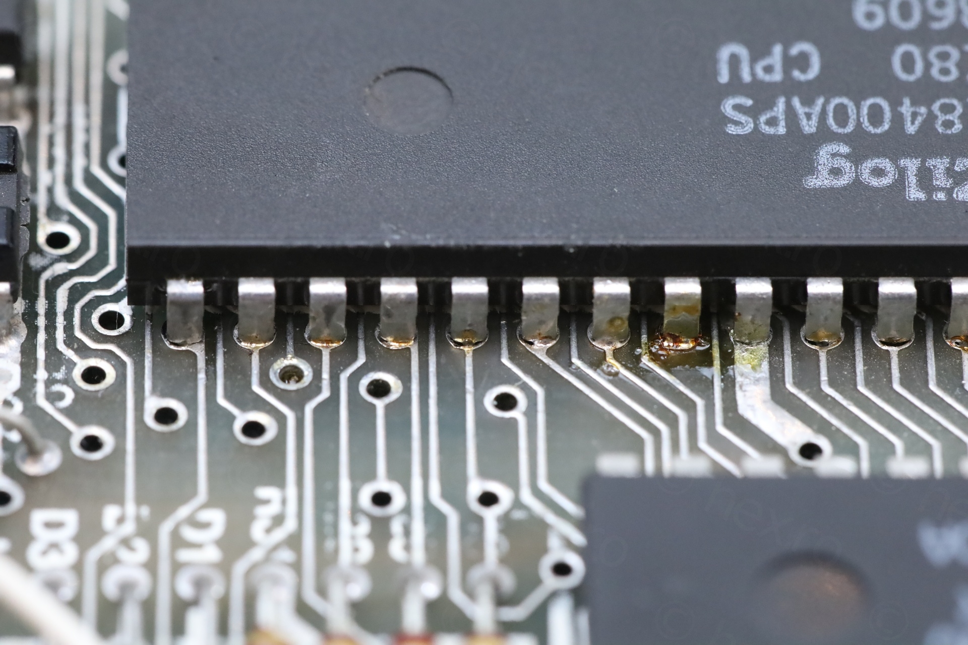
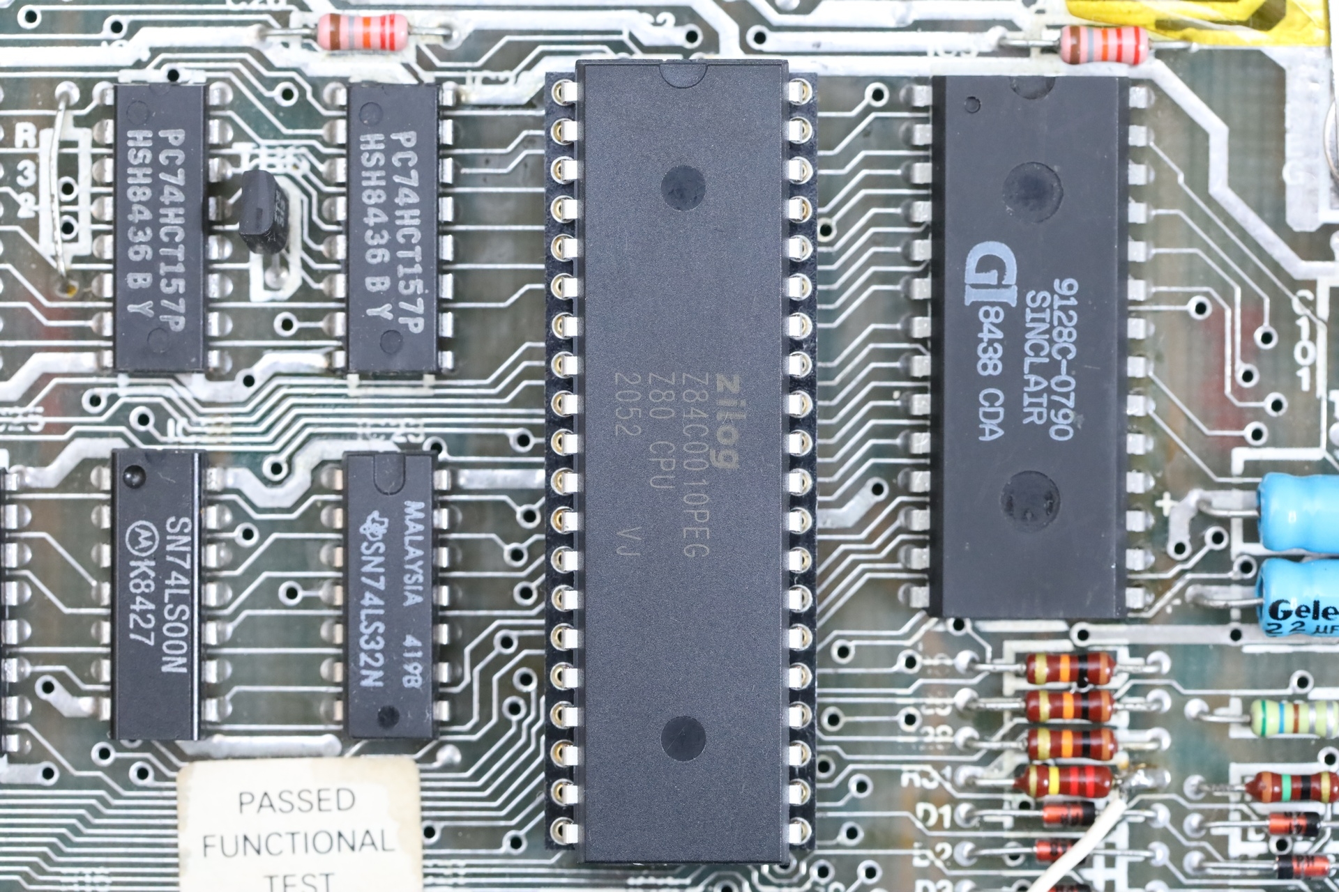
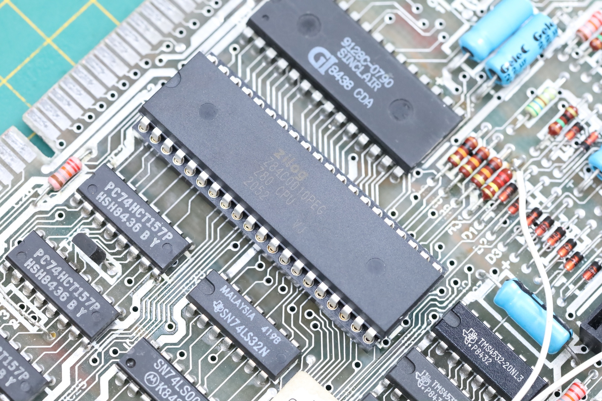
CPU re-soldered
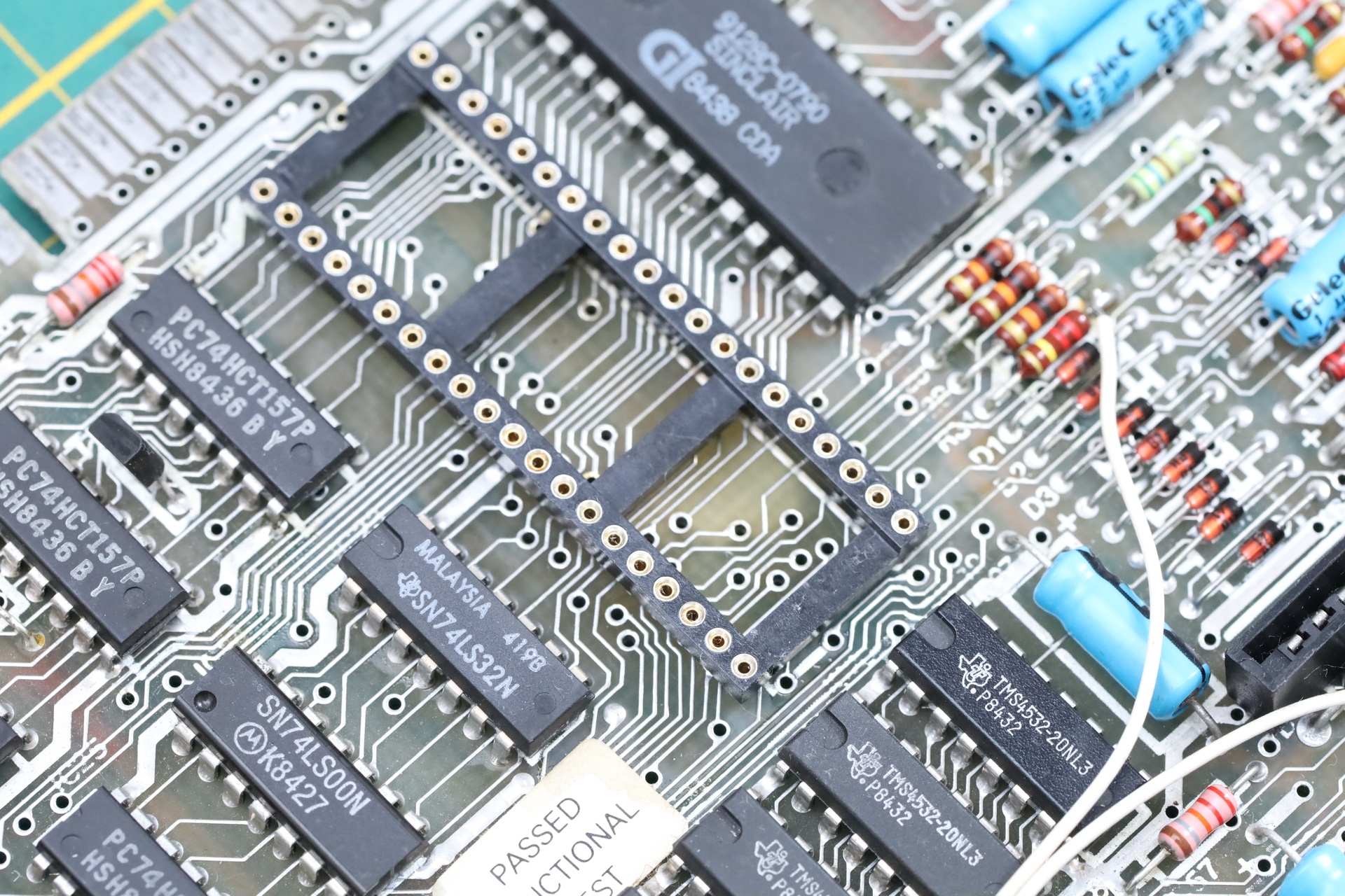
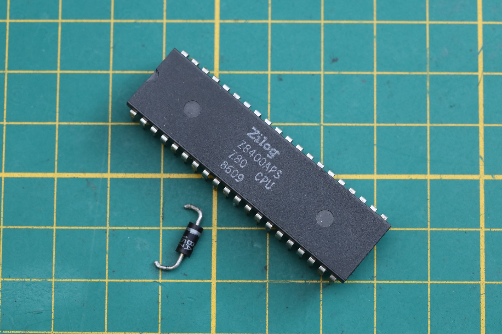
The top view of the CPU did not show any work done, so most likely the CPU was not taken out.
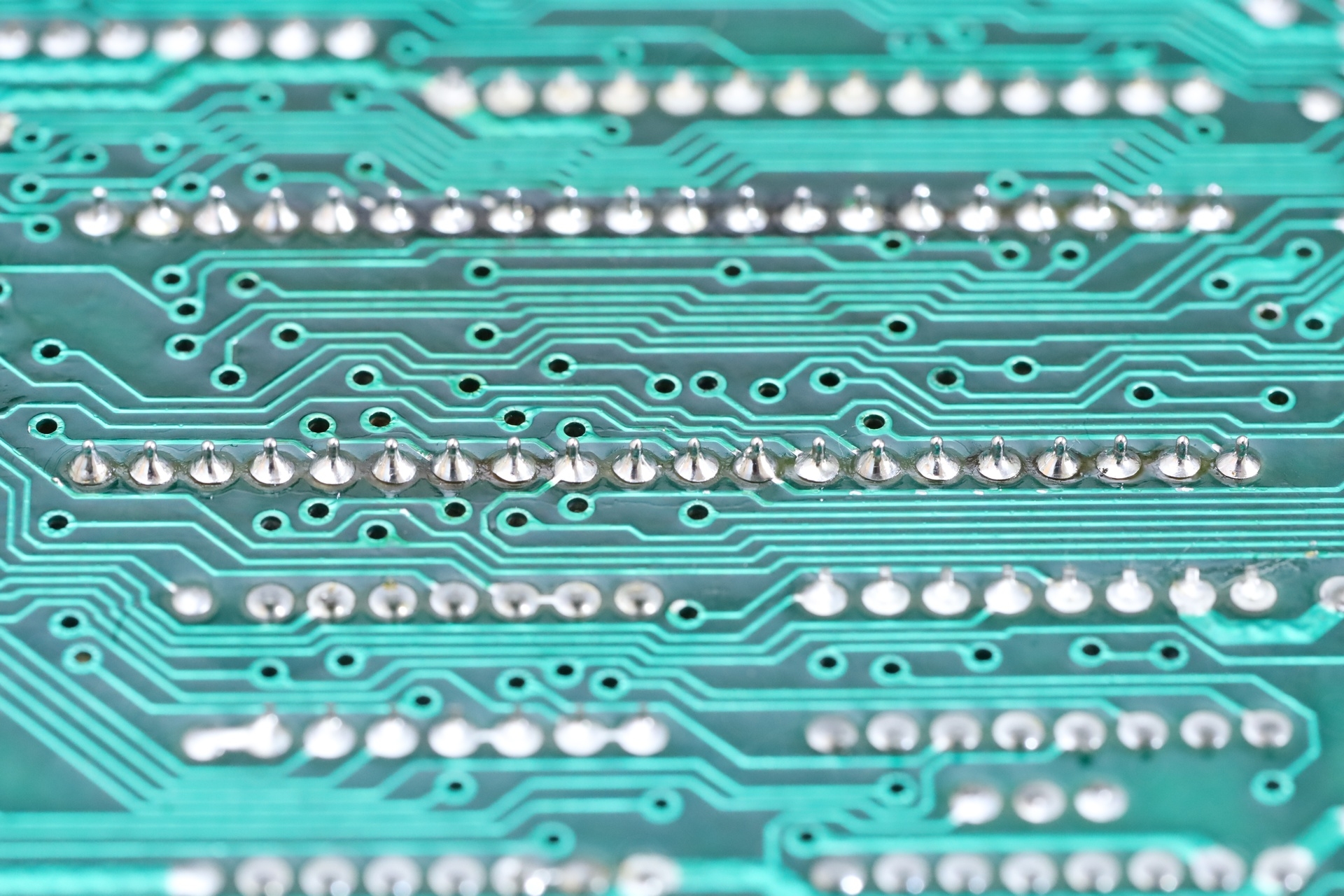
The solder blob looked like it would short across few lines, but it was easy to remove with the fingernail. It did not melt the green coating, thus I doubt it was causing shorts.
TR4 (ZTX650) re-soldered
The TR4 transistor was most likely taken out, measured and put back in, as it was still the original ZTX650 and not some newer replacement.
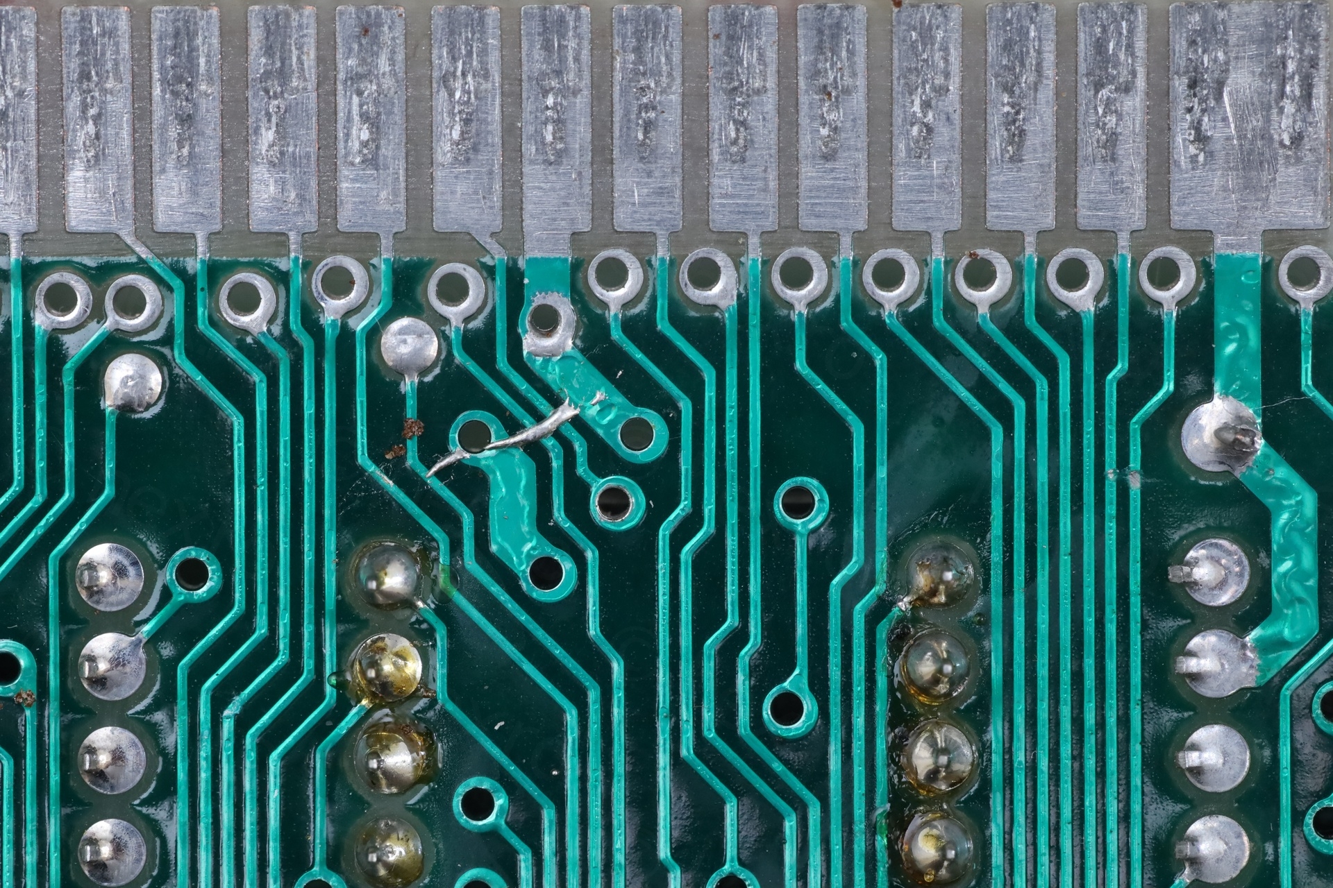
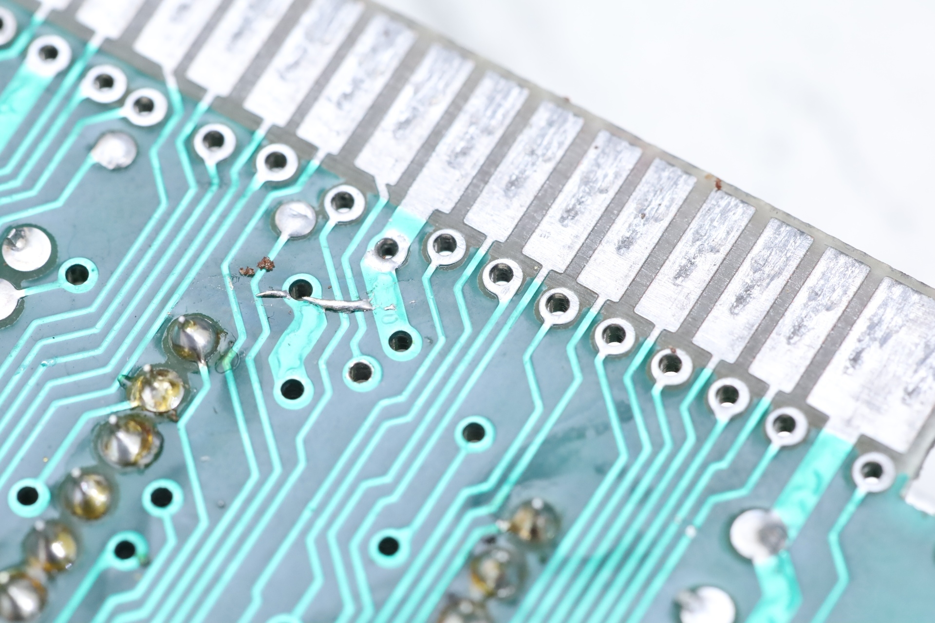
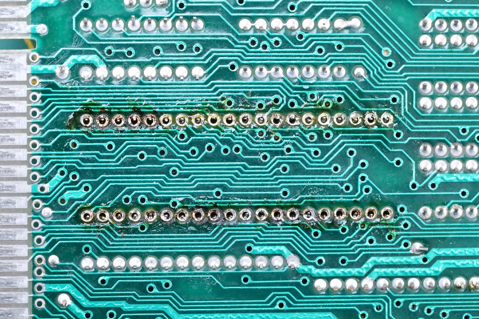
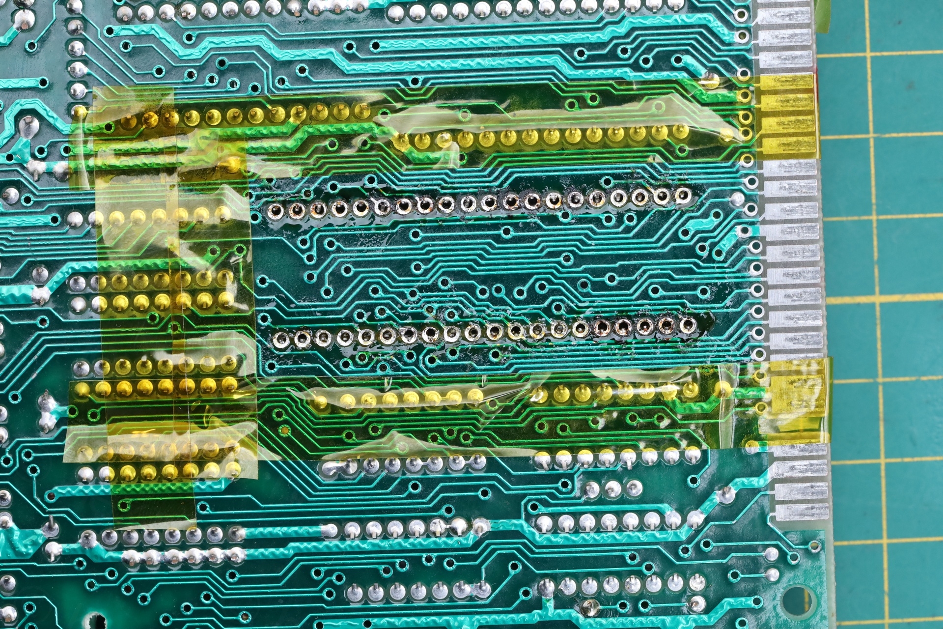
IC13 has broken traces
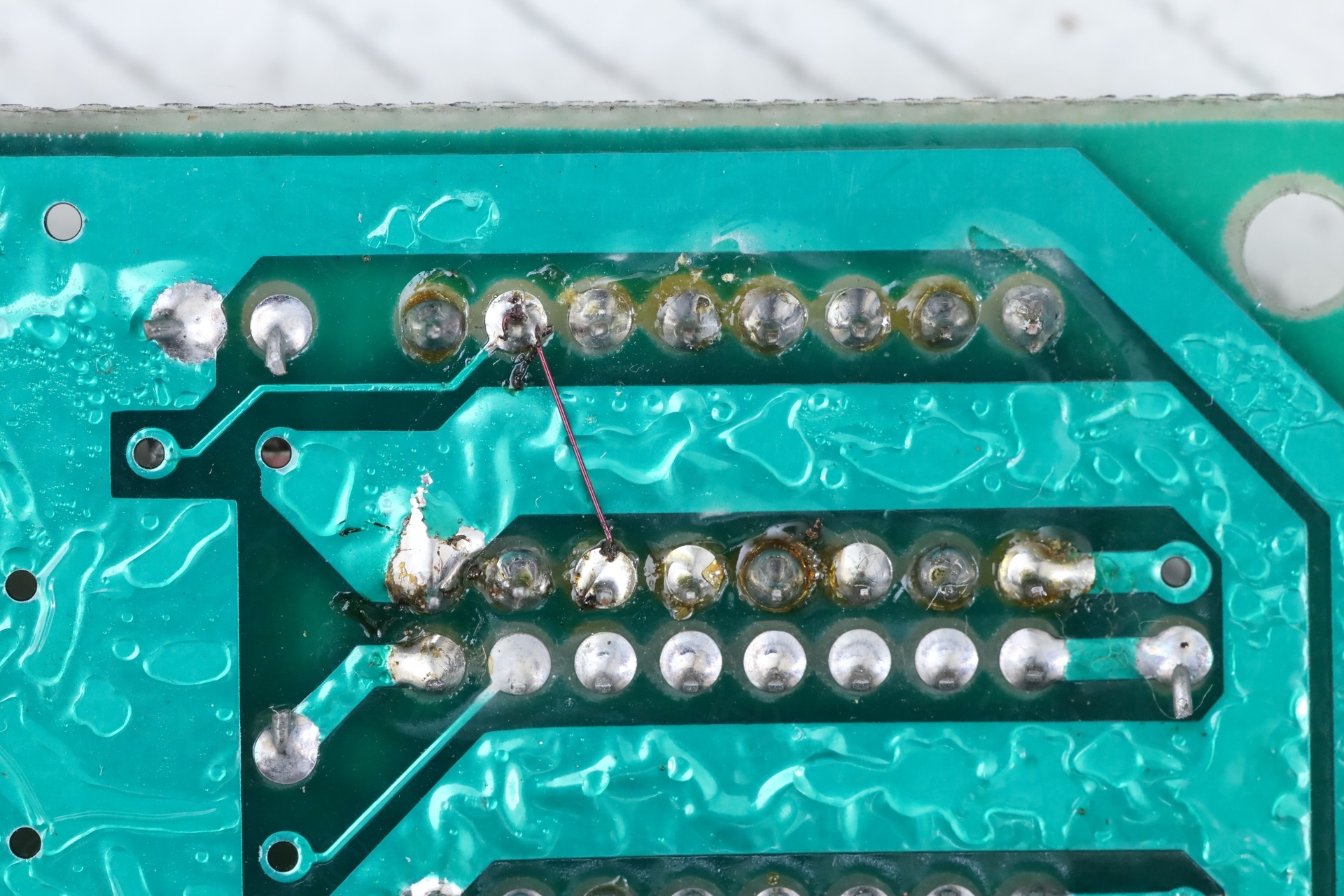
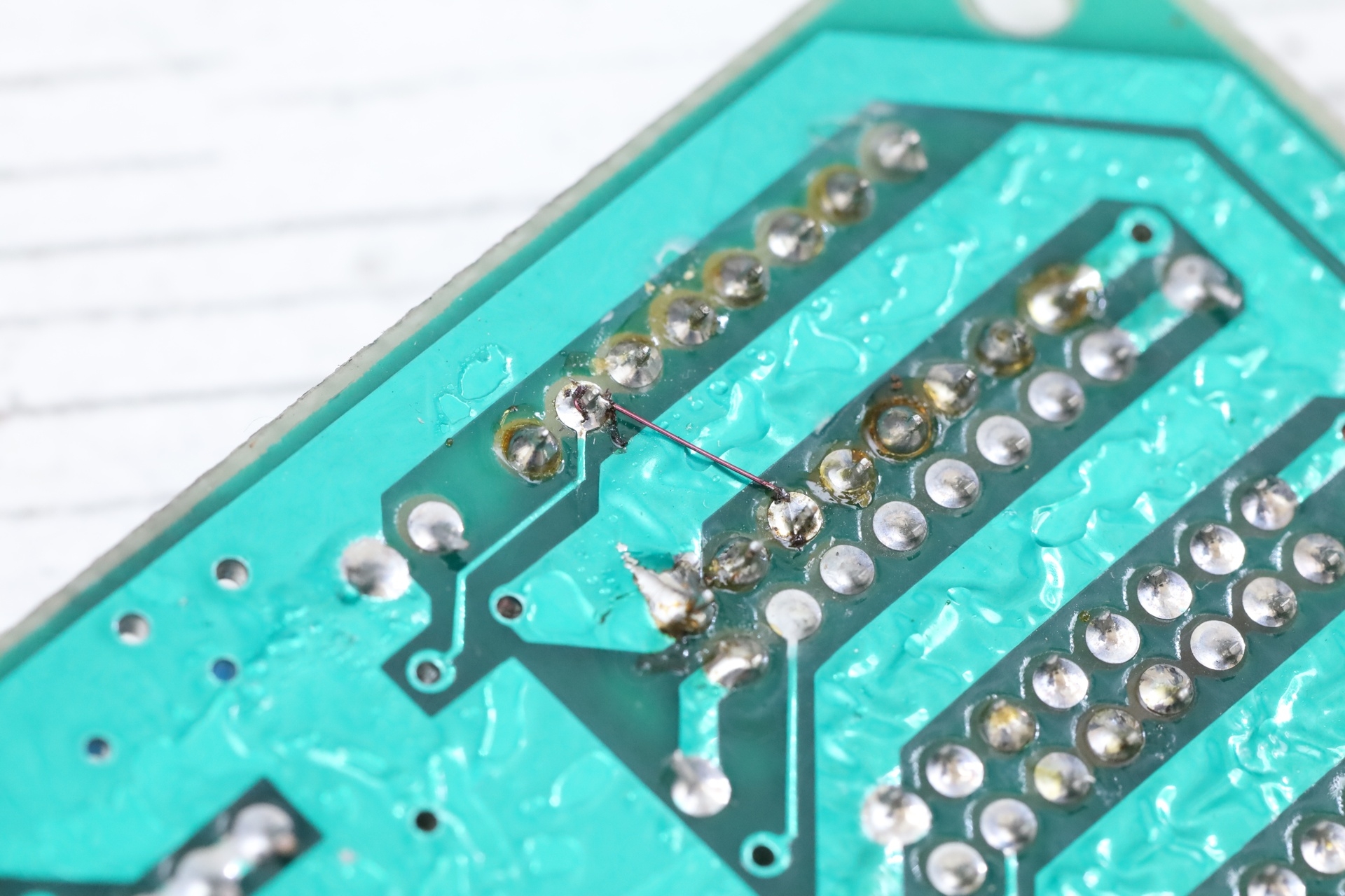
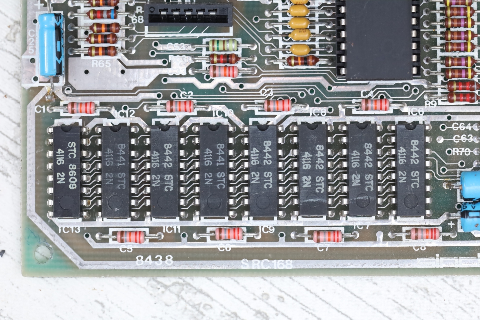
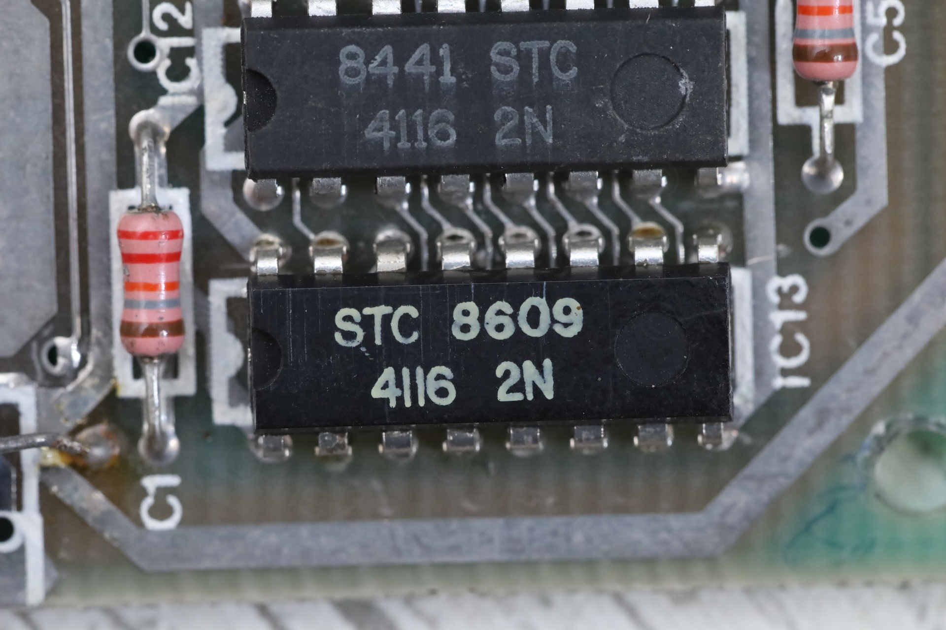
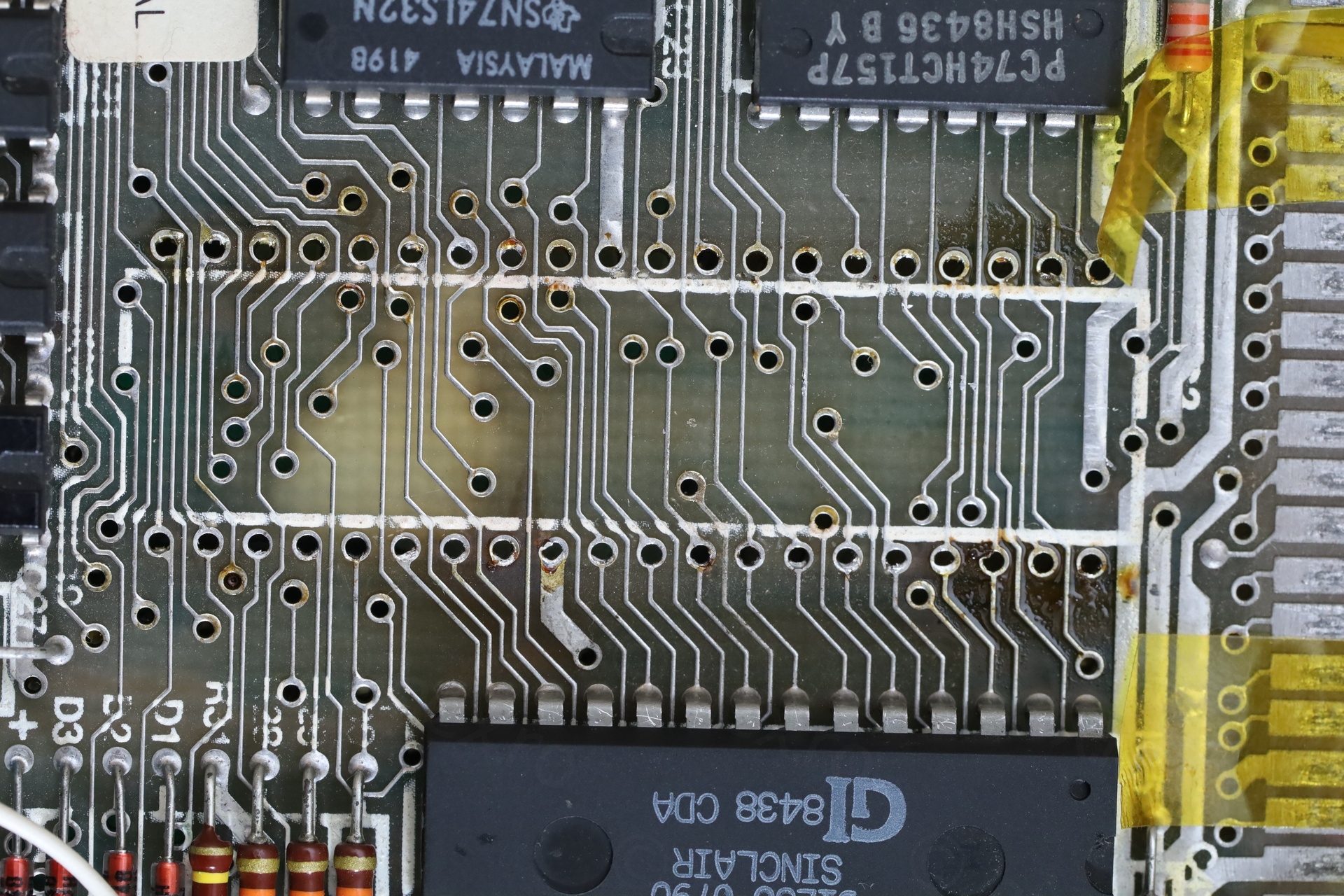
IC13 (first IC on the left corner) has a different date code than all the rest and looks much newer than the others. Its pin 2 and 14 were reconnected on the underside of the board which means that the previous technician broke the trace when trying to replace the old one.
There were no shorts, so I left that wire in place.
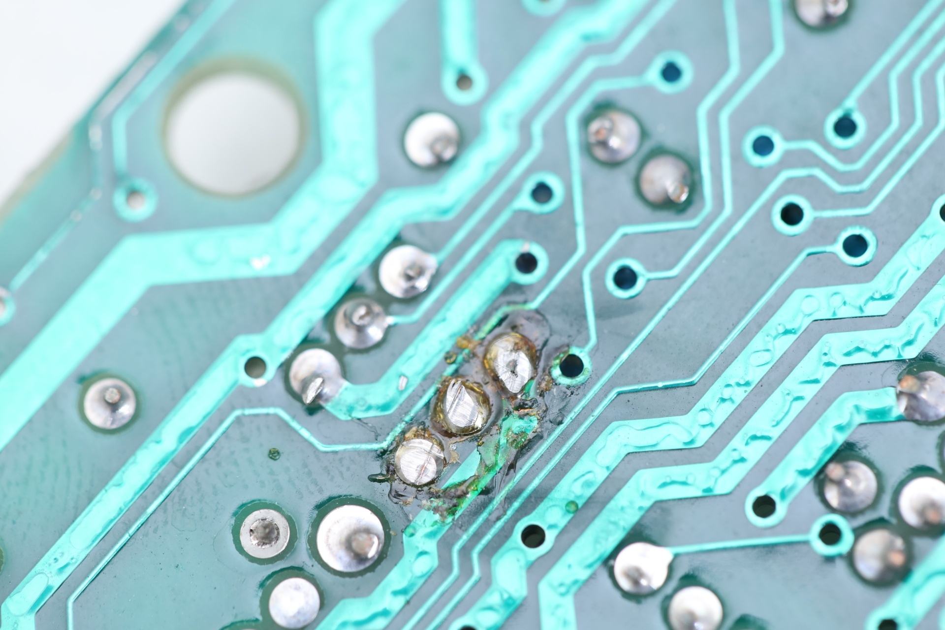
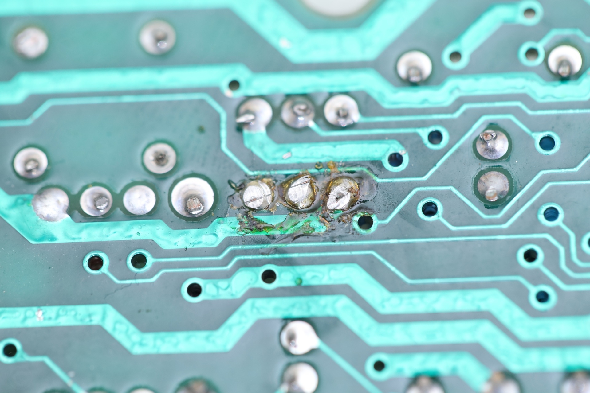
Messy spot
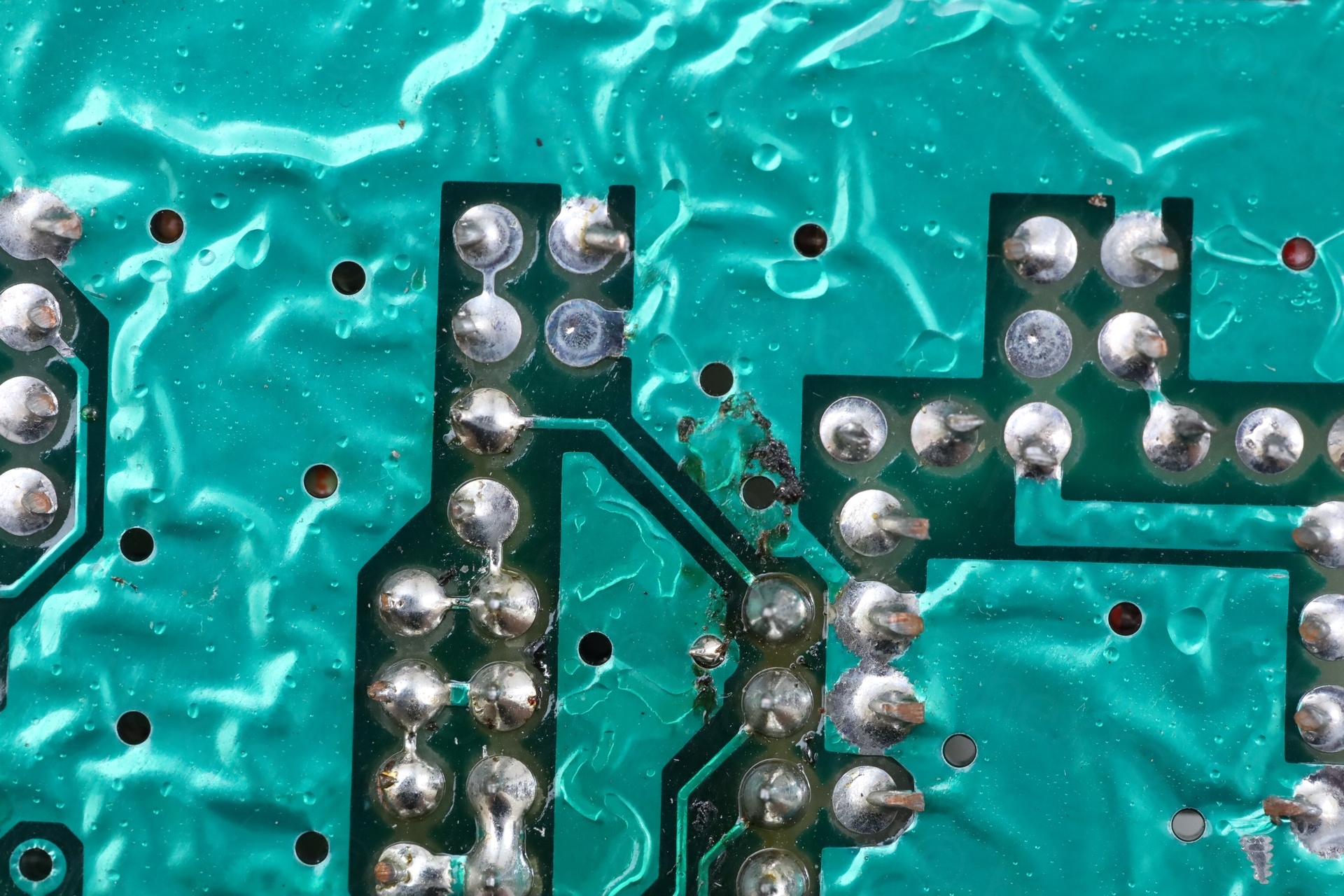
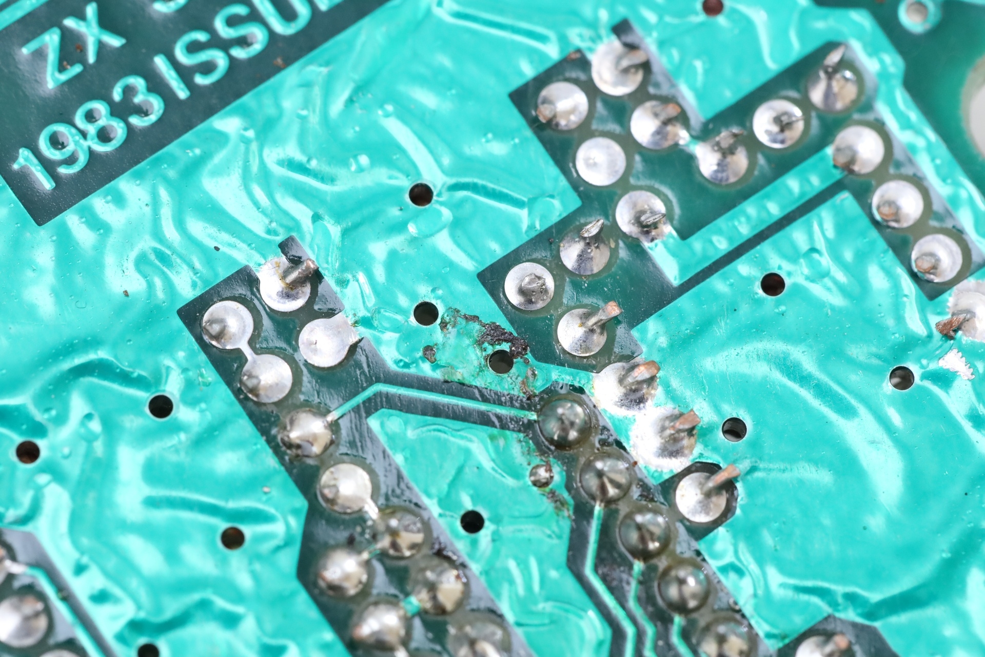
This was easily cleaned with Isopropyl alcohol.
Heatsink with crocodile teeth marks
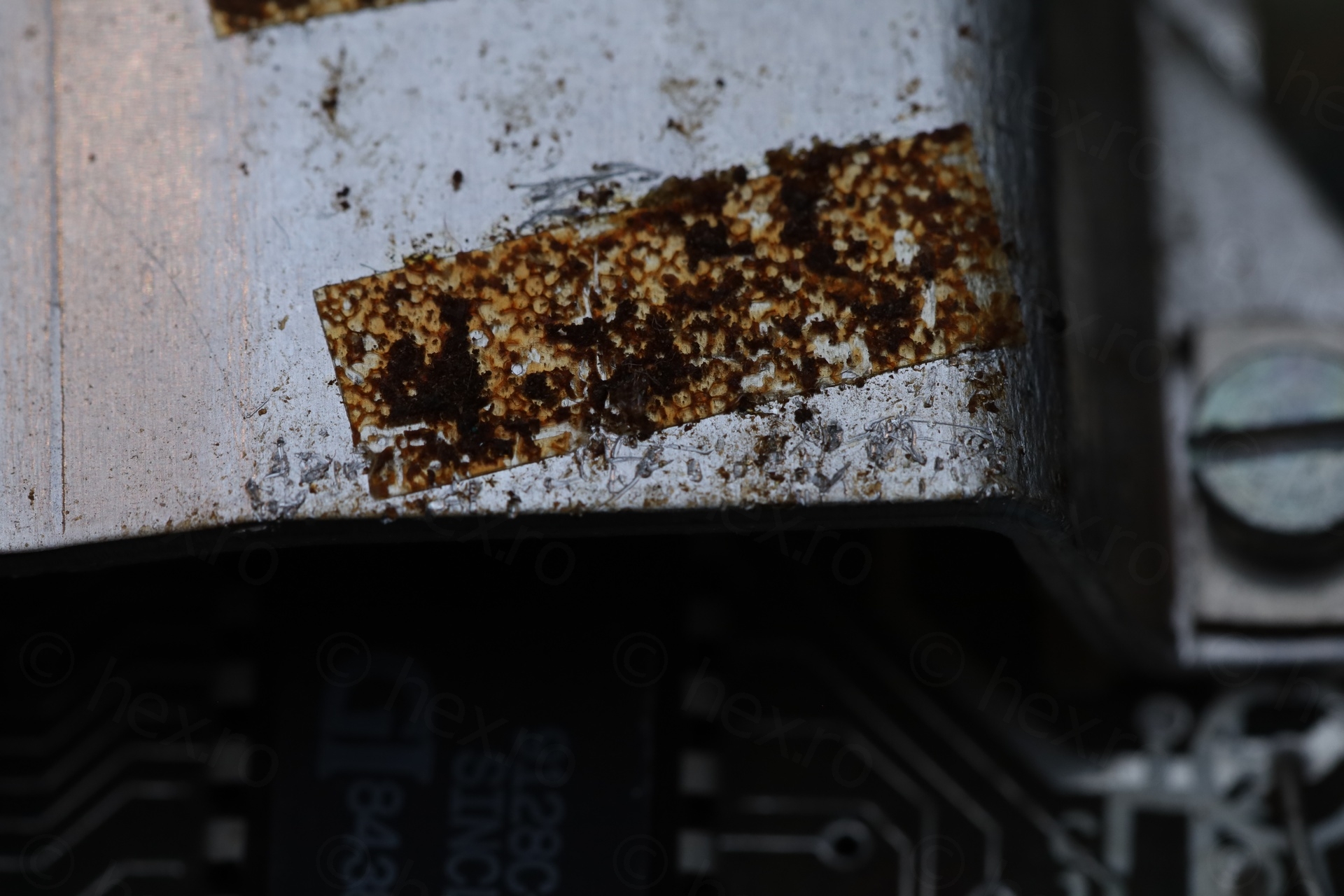
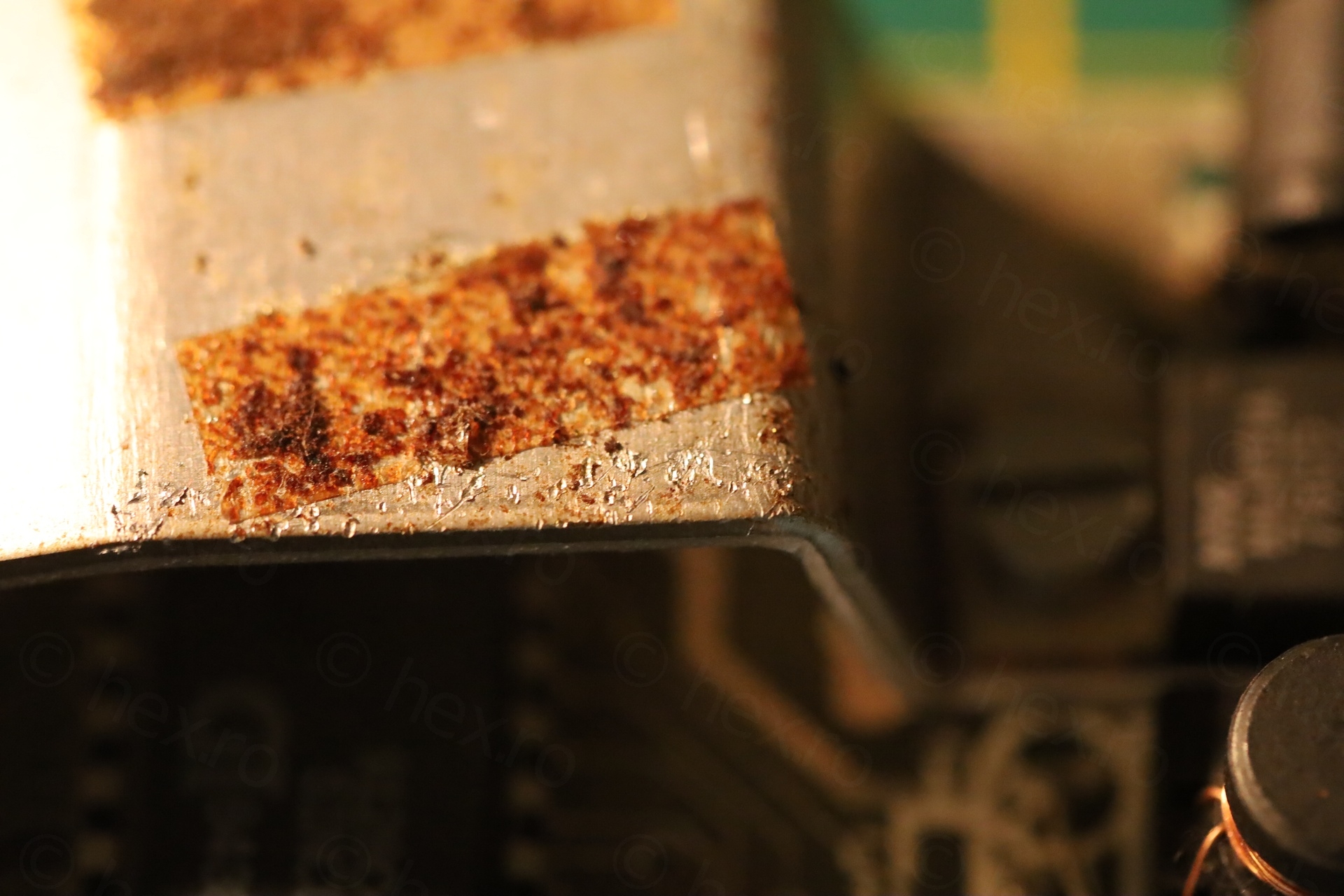
The oscilloscope’s probe ground alligator clip teeth left deep scratches on the heat-sink. Hmmmmmm. What did I get myself into ?
Coil re-soldered
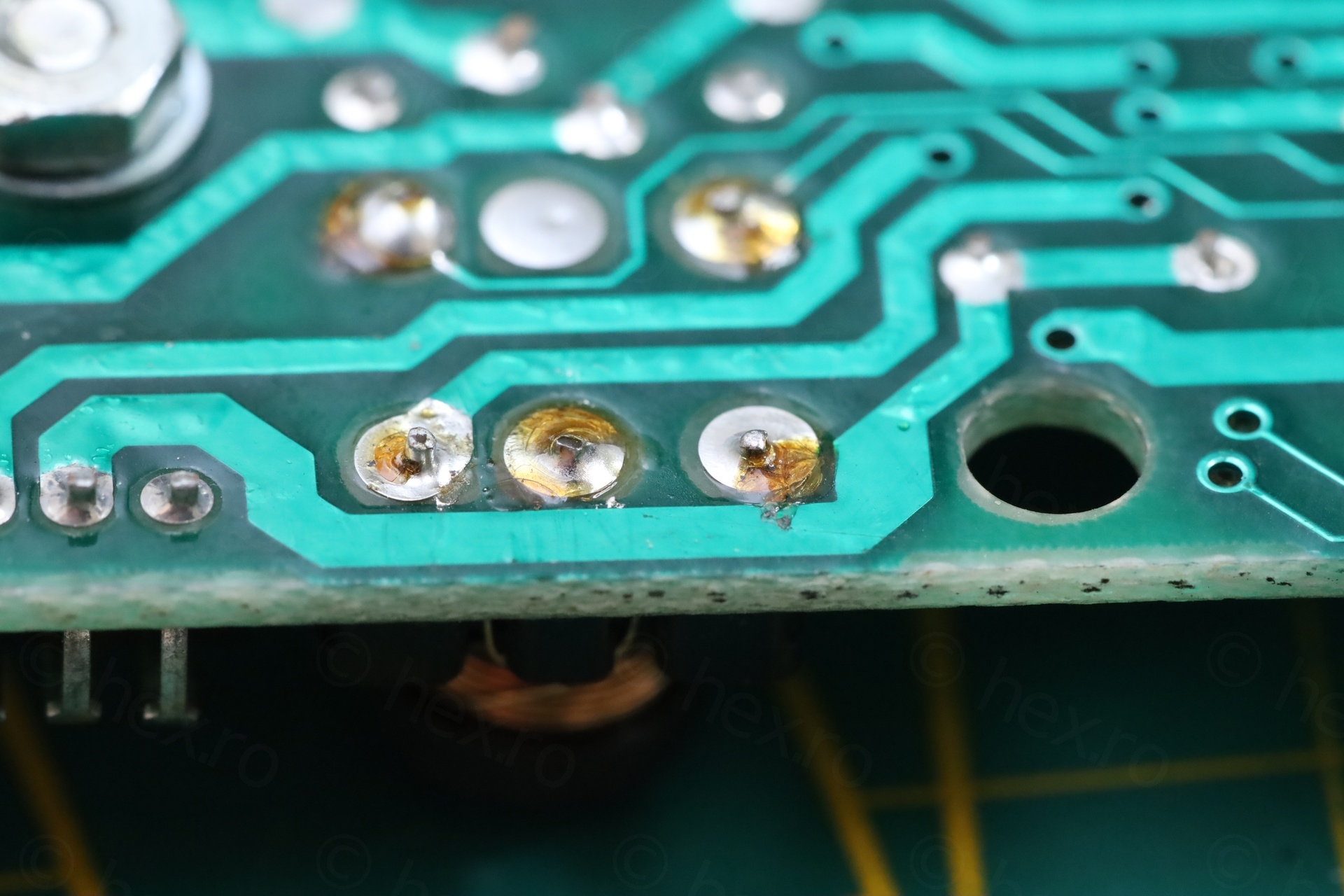
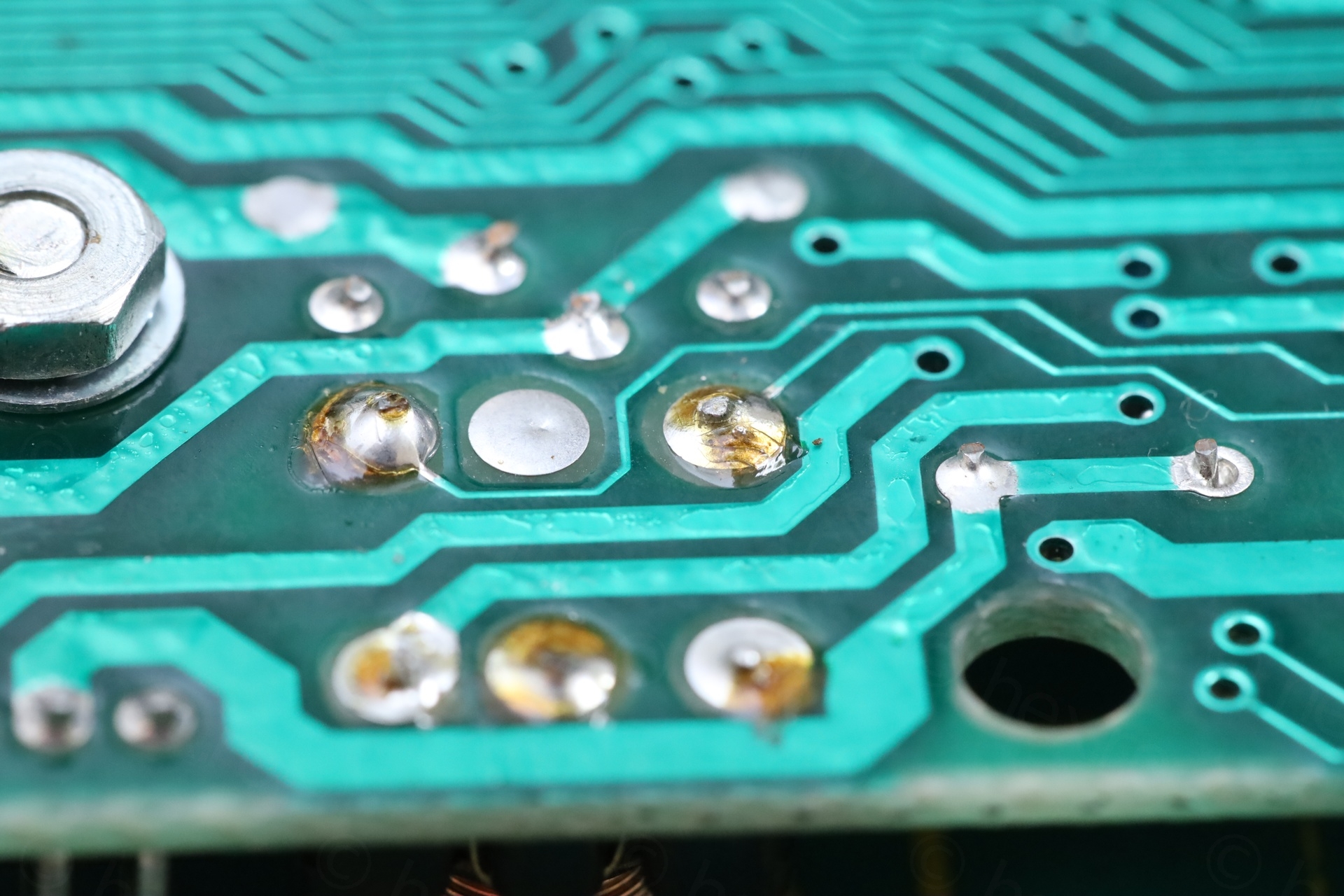
It just never ends ..
Initial tests
Measured voltages on an 4116, they are in spec.
4.998V
12.05V
-5.3V
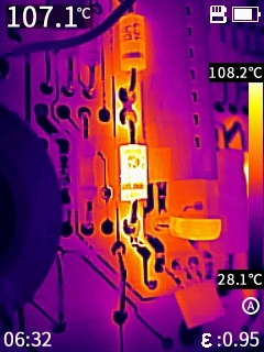
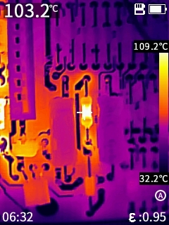
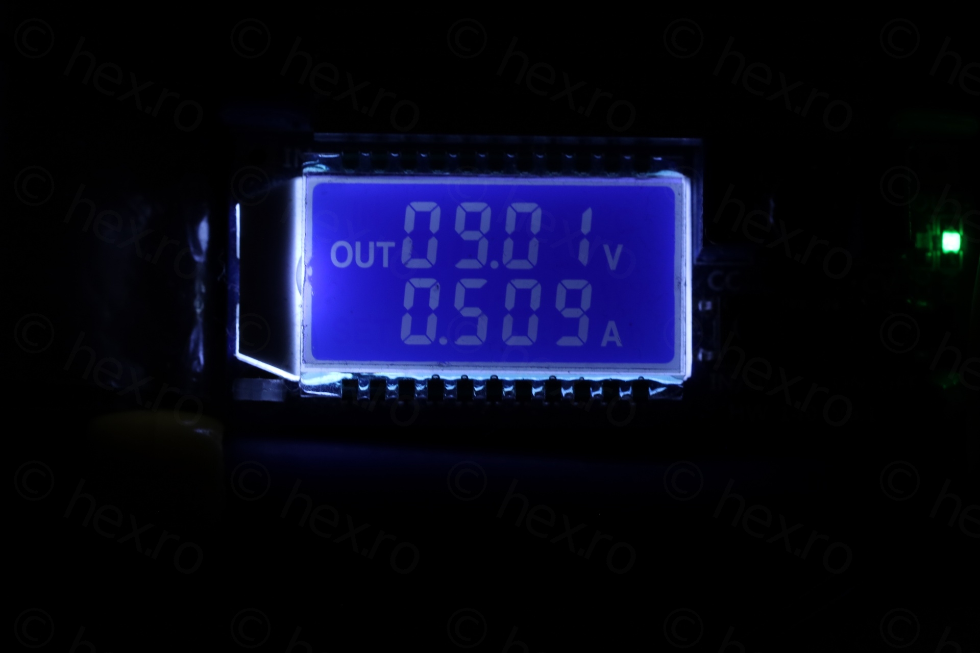
Soon it was obvious the board is indeed defect. Diode D15 was getting very hot, as well as R79 (>100C). Power consumption was erratic. Sometimes drawing 0.65mA, sometimes >1A, without an obvious reason.
It also exhibited a weird startup routine. 10% of the time I was powering it up, it would either keep rebooting, make weird noises, or phantom key presses all by itself:
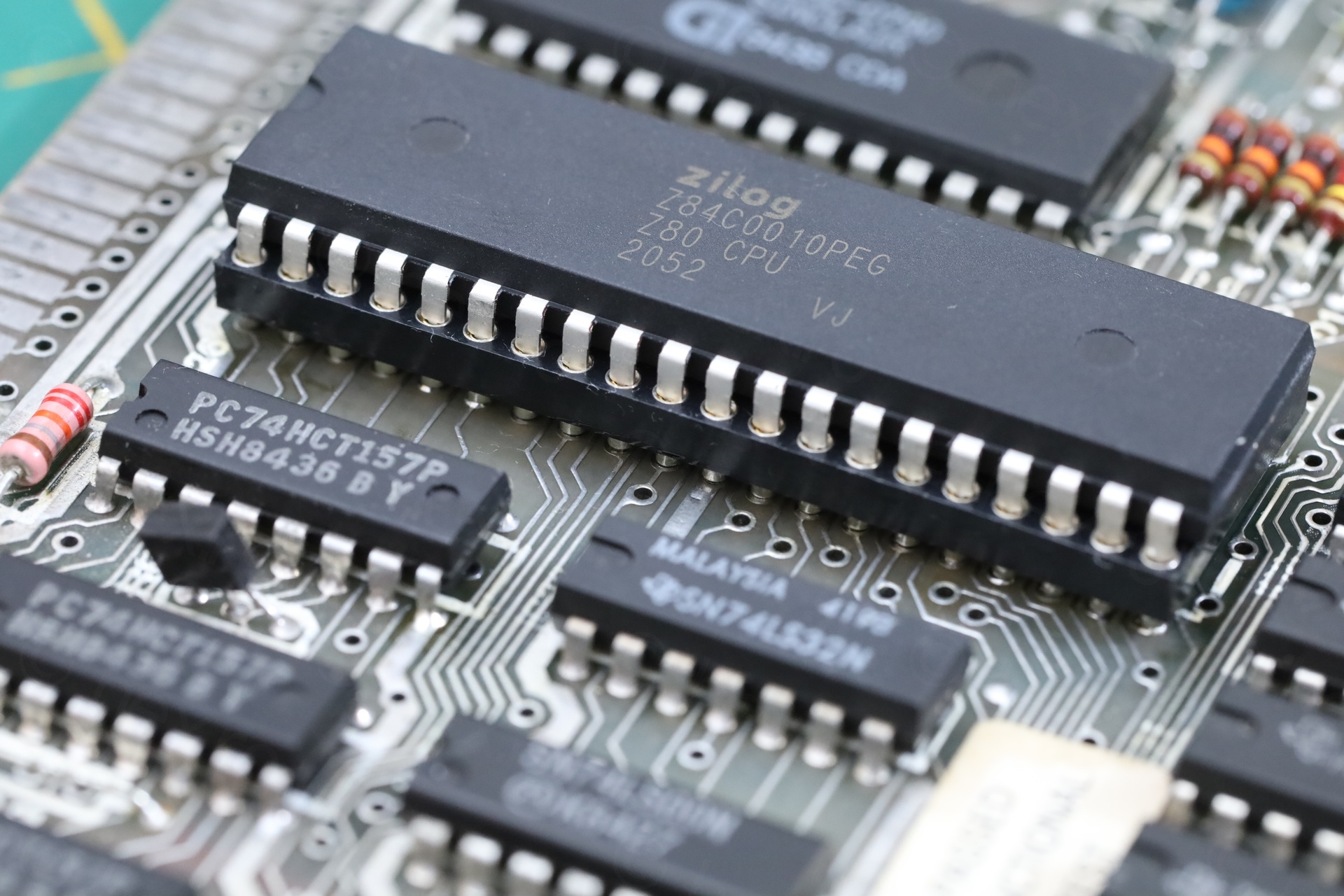
Trouble was that re-plugging the power very often fixed the issues; it was hard to capture it on video as above. And when it finally powered, the diagnostic ROMs were passing with flying colors.
To make it more challenging, the CPU and ROM were also getting hot …
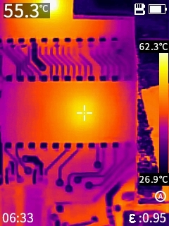
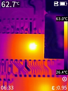
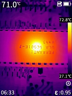
… but a lot of forum posts on the internet were saying that except ULA, the other two, CPU and ROM, they should run cold. So which one is it ?!
Diagnostics
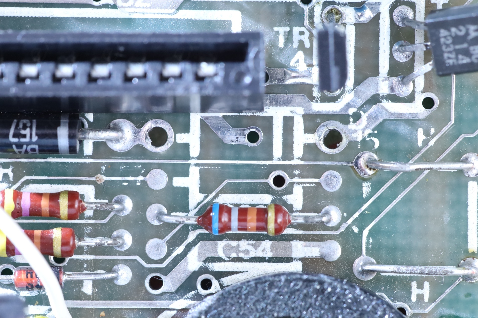
D15
I dislike the shotgun approach, swapping parts hoping to get it to work. I kept measuring, thinking and searching the web. The ESR of the capacitors were a little high for my taste, but I doubt capacitors could cause these issues. So I left them in place.
One more weird thing was that a diode test over TR4 (with red lead on collector and black lead on emitter) was showing a voltage drop of 1.7V. I took the TR4 out to measure it, but it measured fine outside the circuit, so I put it back in.
Searching Google more for “R79” hot or “D15” hot, I ended up on two websites, one where somebody was stating that replacing capacitors fixed the temperatures and second one was from the repair manual here https://k1.spdns.de/Vintage/Sinclair/82/Sinclair ZX Spectrum/Repair/ZX 48k repair guide (ian worsley)/rep_spec.html , where it is mysteriously said that: “You may also visually check , to see that R79 2k2 (Issue 6) or R62 15R (Issue 6) or R55 56R (Issue 4 and less) are not discoloured. If any of the 55R resistors are badly discoloured, change D15 BA137 on all models.” (emphasis mine).
If R79 runs so hot that that it can get discolored, change D15 ?! Where did this come from ?
But with no other smarter choices, I decided to pull D15 out, since both my R79 as well as D15 were getting very hot. The diode was measuring fine in circuit (no shorts, and open one way). However, the interesting thing is that after I measured it outside the circuit, it said 0.745V voltage drop on the DCA75 meter. One more test, 0.8V. However, a good BA157 replacement shows 0.600mA. It seems to also be very temperature sensitive. A quick spritz of CO2 spray makes the forward voltage be 4.5V.
Still very puzzling although I would be happy if this is the culprit.
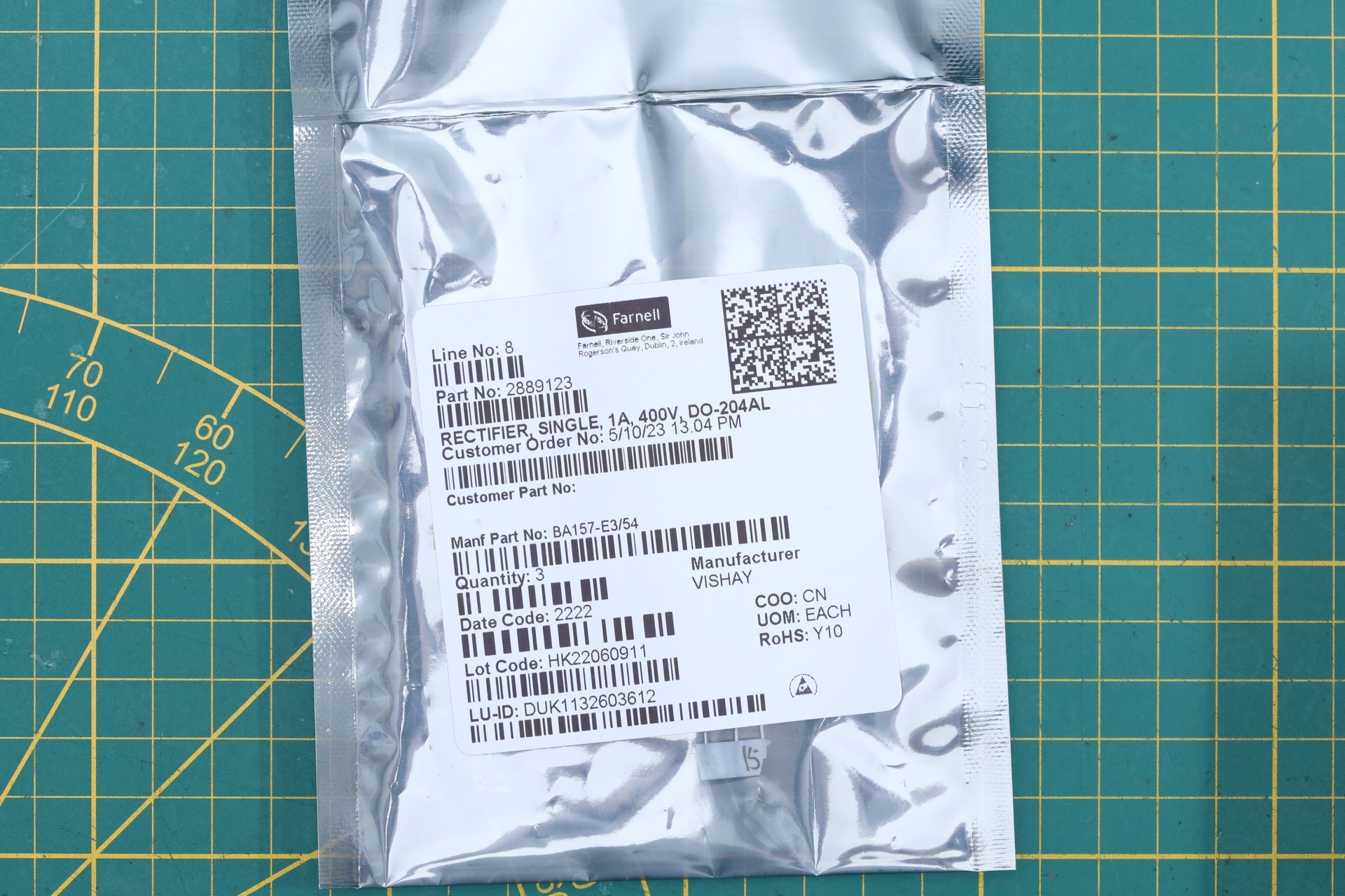
I have ordered the exact replacement, BA157 but even if Farnell does do next day delivery to Belgium, all my past orders were stuck in customs with UPS. Which meant I have no spare for the weekend. Oh well… eventually, they arrived.
I cleaned the board and proceeded to install the new diode.
The replacement:
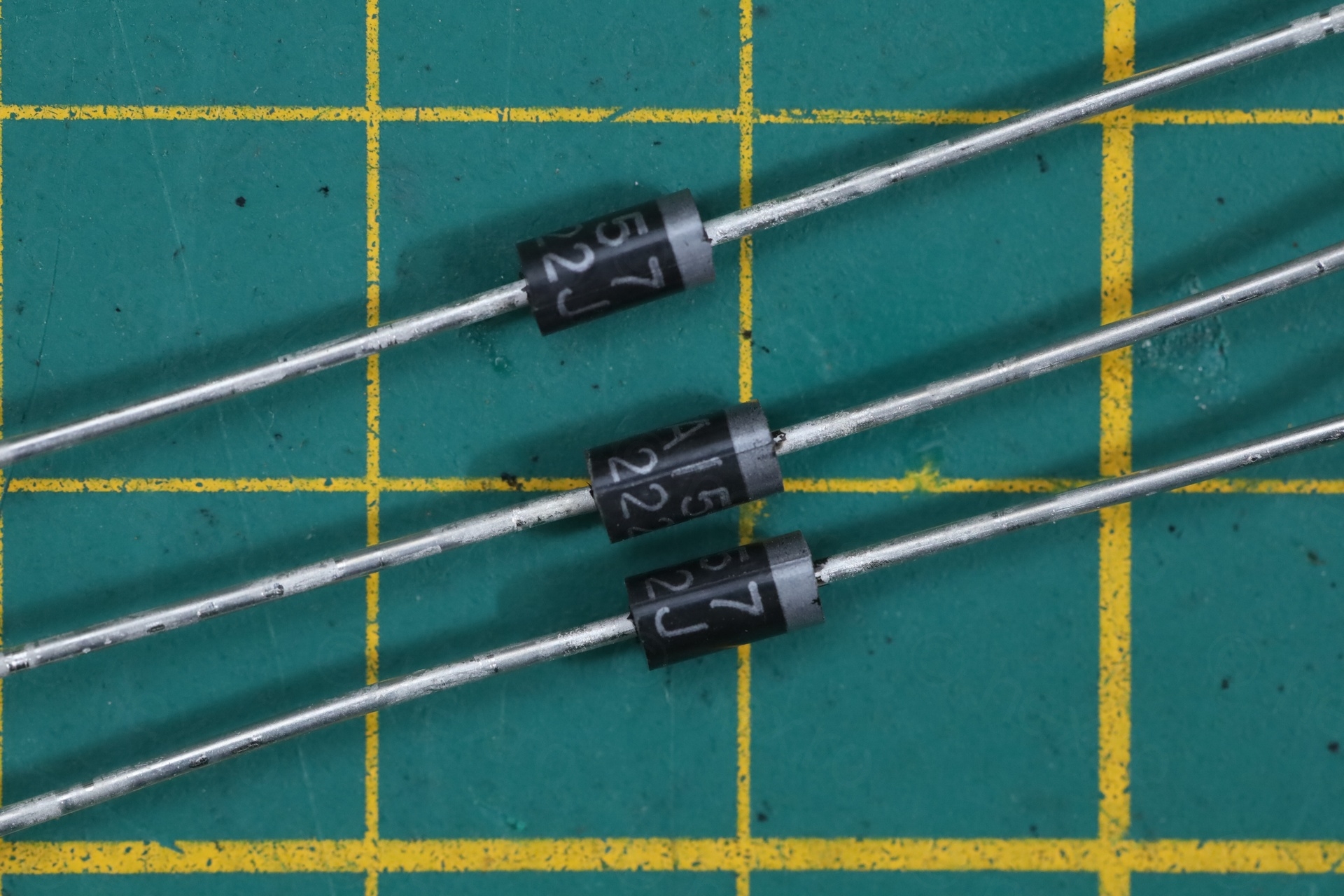
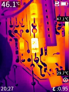
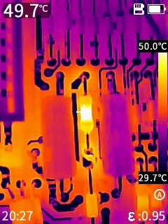
The replacement did change things exactly as the manual said. I first checked voltages, and they stayed similar (0.1V less for the both the 5V and 12V line, and 0.1V more for the -5V line which now was at -5.2V). Neither the new diode, nor the old resistor were getting hotter than 50C (while they were running at >100C before):
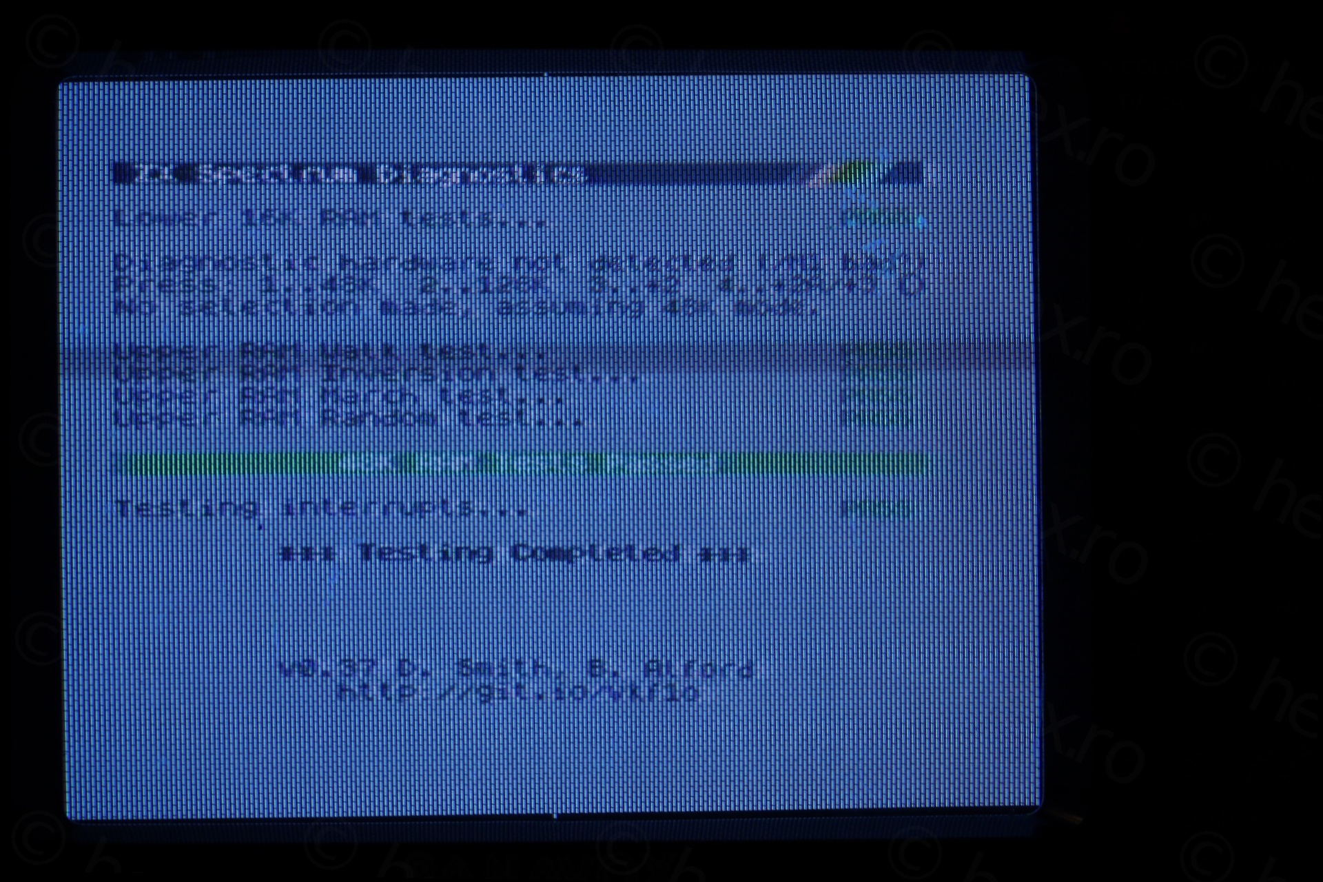
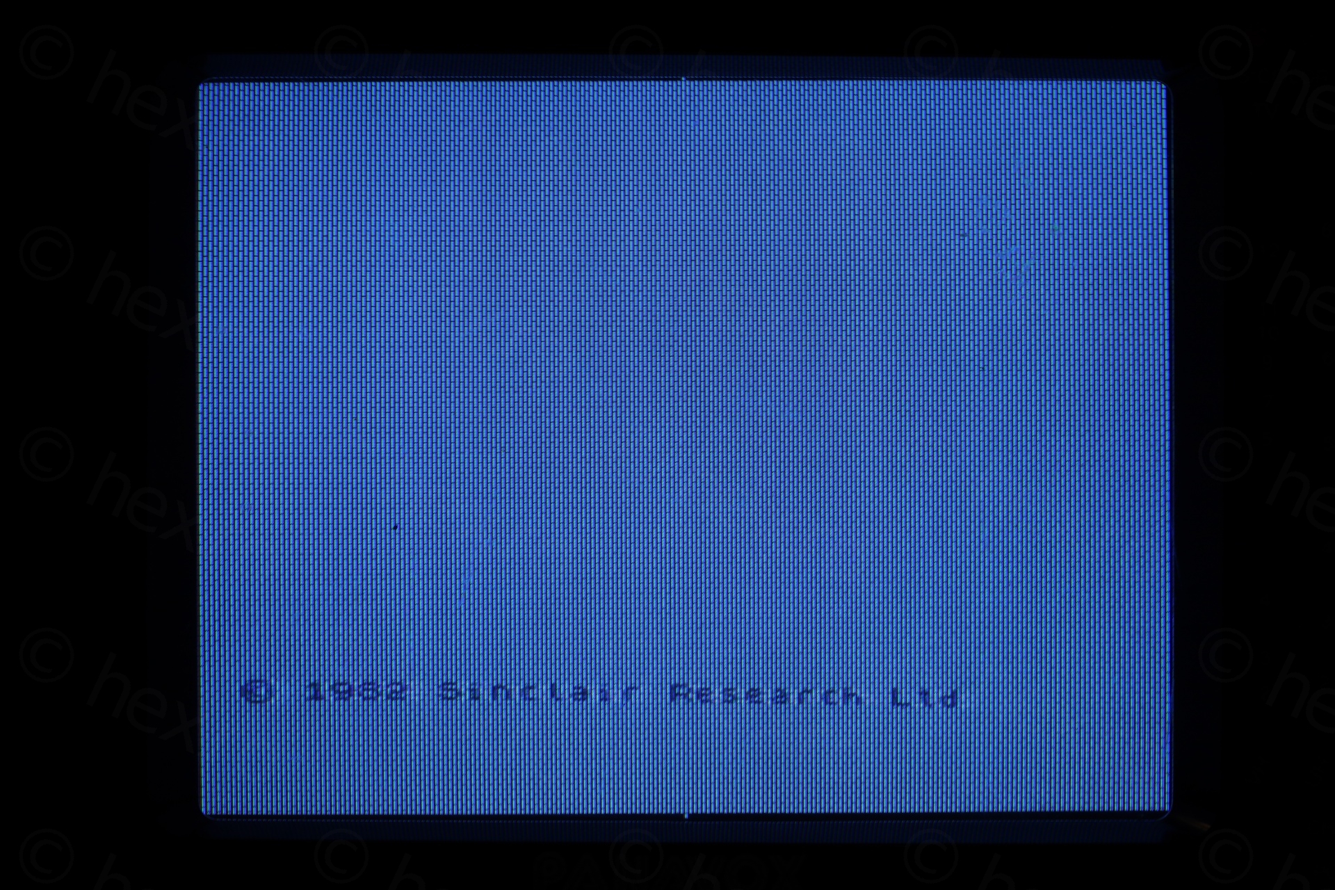
But some things got worse. The computer did not boot anymore. The Sinclair ZX Spectrum board was stuck with black vertical bars – sometimes with random squares appearing:
CPU
The new ULAs replacement vLA82 have arrived – and swapping the ULA chip did not improve anything. ULA is the first thing to check, the manual insists.
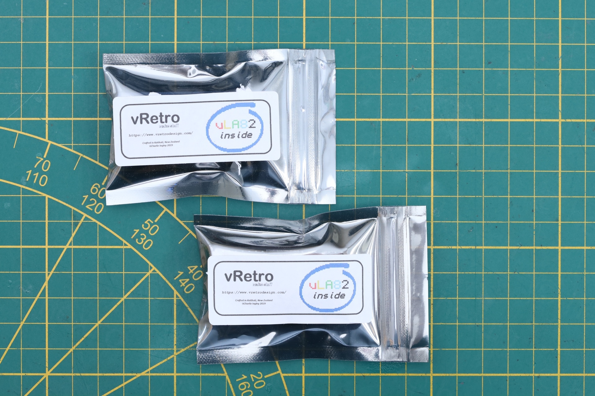
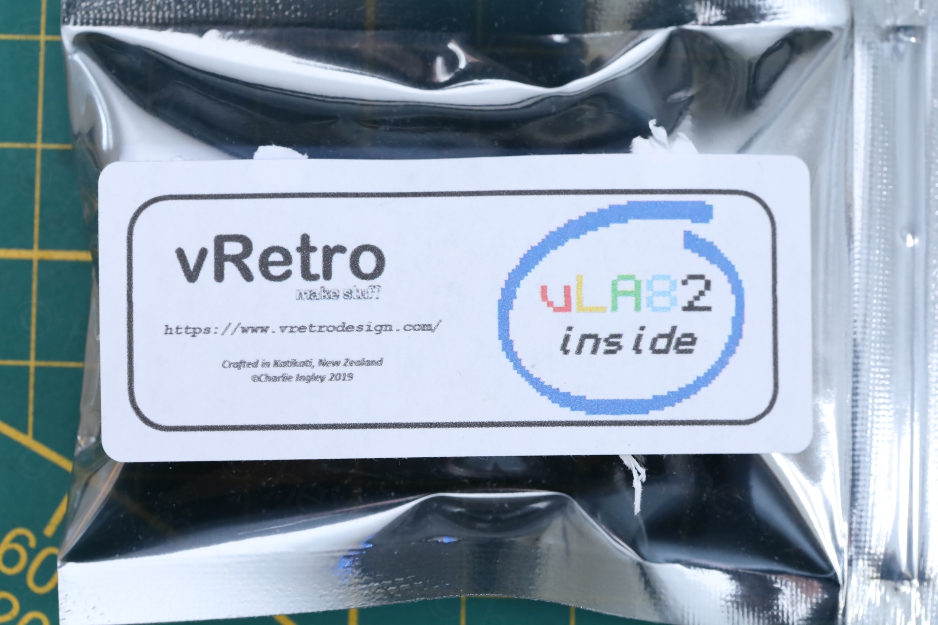
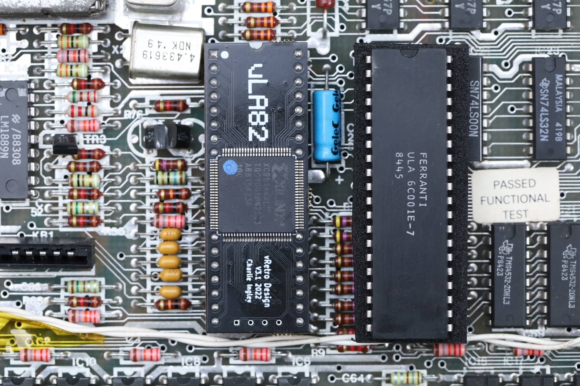
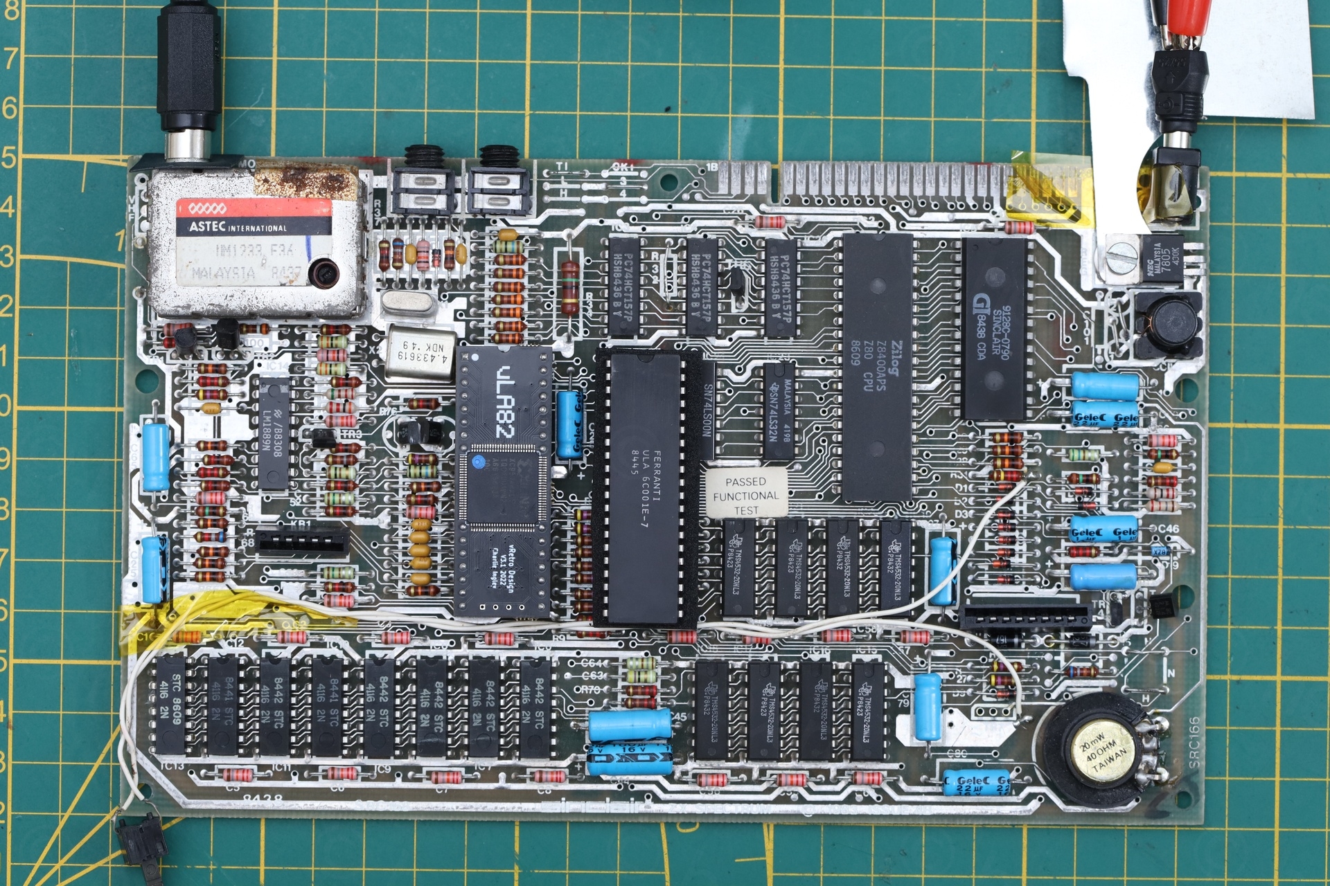
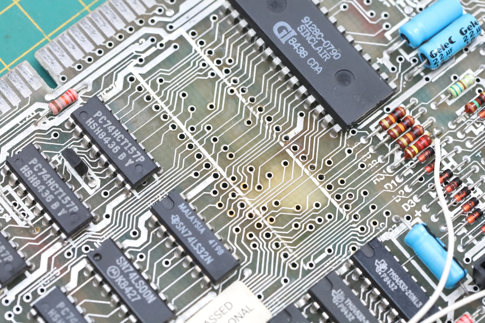
I am very happy I have bought the vLA82 boards, which are drop-in replacements for the original ULA. I can protect the irreplaceable ULA by using a modern replaceable board. I continued debugging the motherboard using the new replacement. On the top right you may notice my adhoc heat sink, allowing the 7805 to stay around 60C at least, while I was probing around the CPU / ROM area.
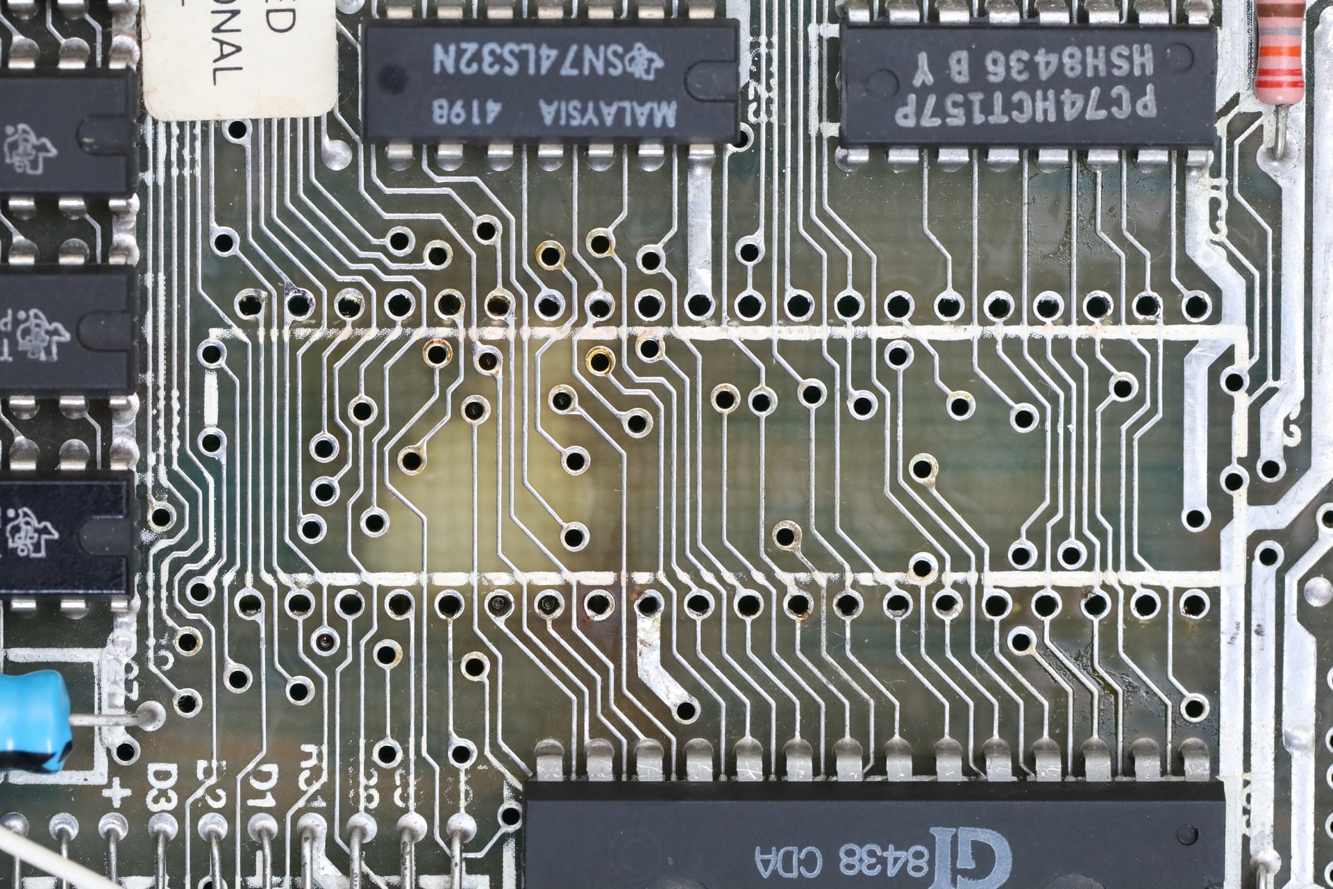
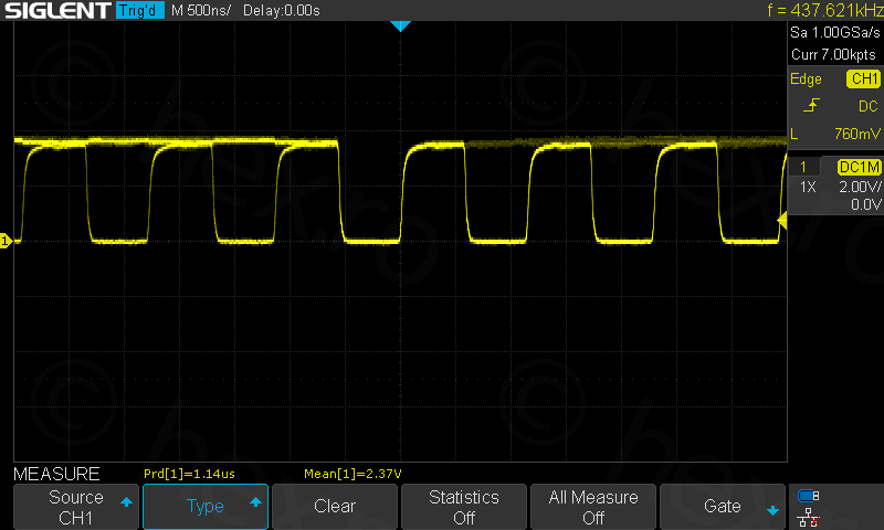
Looking around with the oscilloscope, I spotted that on IC25, while all signals bounce up and down to 5V, the signal on pin 11 was only going up to ~1.8V:
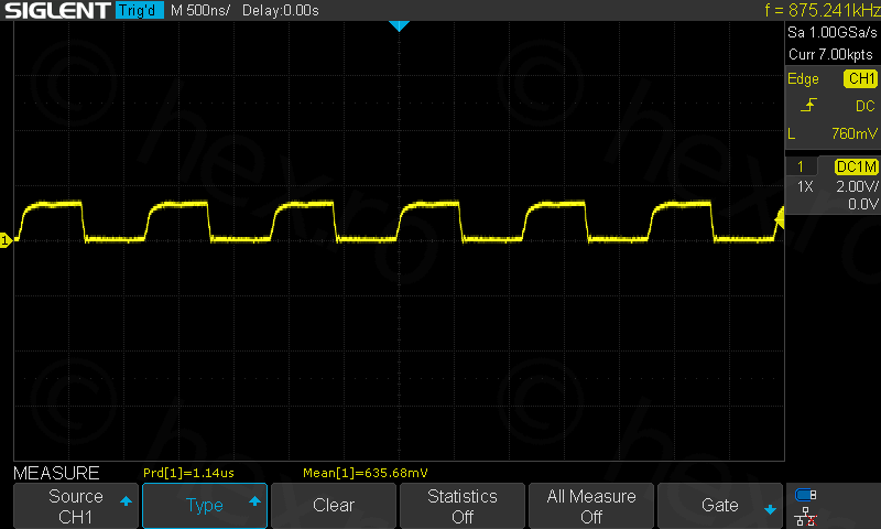
Checked D2 (linked with IC25::11) in circuit, it was fine. It is also connected to IC3::11, IC5(ROM)::21 and IC2(CPU)::40 – the faulty address line is the A10 line. There is some de-soldering to do to isolate which chip keeps it at 1.8V instead of 0 🙁 since all these ICs are connected in a loop.
I still abstained to start de-soldering – it is very easy to do it, but I this is not the board that a customer waits for me to fix… thus I forced myself to reflect – was it the CPU or the ROM ? A sign that it was probably not the ROM was that the board freezes even with a diagnostic ROM connected to the expansion slot. But it may also be that a faulty ROM would keep the A10 low enough, right ? Hmmm.
CPU is getting hot; it seems capable of limiting the A10 line to 1.8V just like the ROM could, but it also seems to freeze after executing few instructions (sometimes border is white, sometimes it has vertical lines, etc). ULA also freezes, sometimes keeping the sound pin HIGH, overflowing the poor TR7 sound transistor which gets hot quickly. But sometimes ULA freezes with having the sound pin LOW. But I know it is not the ULA, since I tried with both – original ULA as well as the vLA82 replacement.
I decided to pull the CPU. It seemed to me the most logical step to start with, although it was the biggest to de-solder.
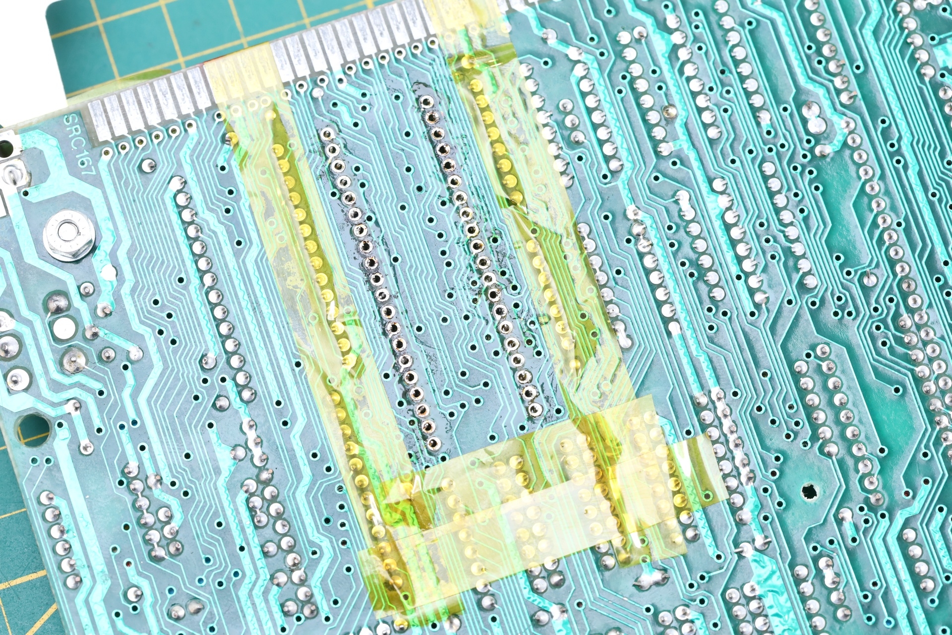
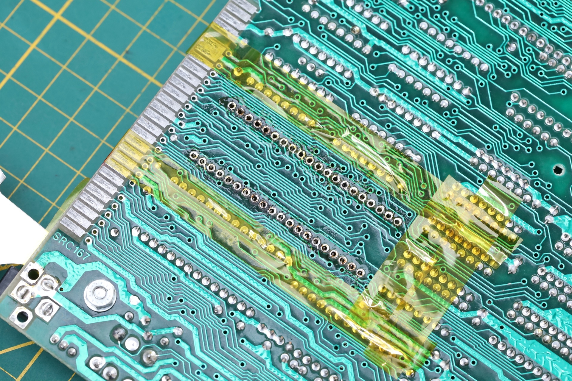
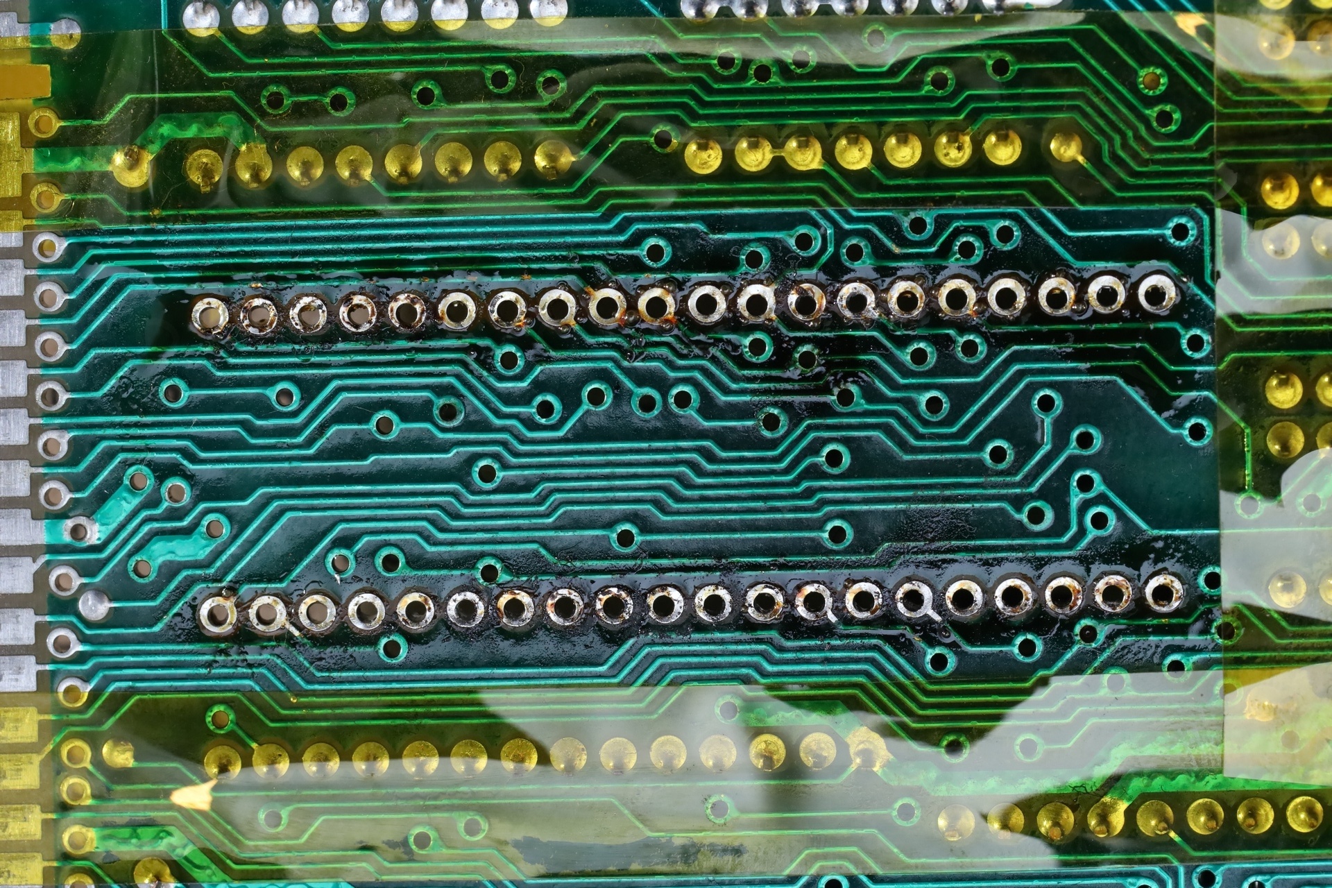
The extraction was not easy, I threw everything I had at the board. Started off with a vacuum pump, but there were still little bits of solder squeezed between the CPU pins and the through-holes walls, keeping the pins captive, and the CPU impossible to release without tearing something down. I could not clean that solder even with de-soldering braid + lots of flux. The last remaining attempt was with the heat gun.
At 350C with medium nozzle and air flow, starting from afar then getting closer, I was finally able to dislodge the CPU without putting pressure, saving the pads and not breaking any traces:
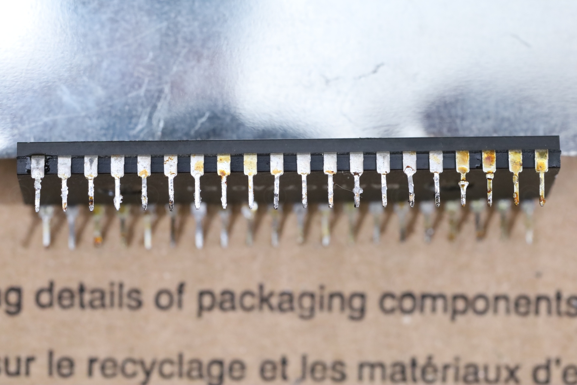
I also found that some pads on the top had broken edges but under the CPU, meaning, I was not the one causing them since I never reached there. Maybe the CPU was swapped by the previous person also ?
I touched up the edges of the pads on top, installed a socket and one new CPU that I ordered from rs-online:
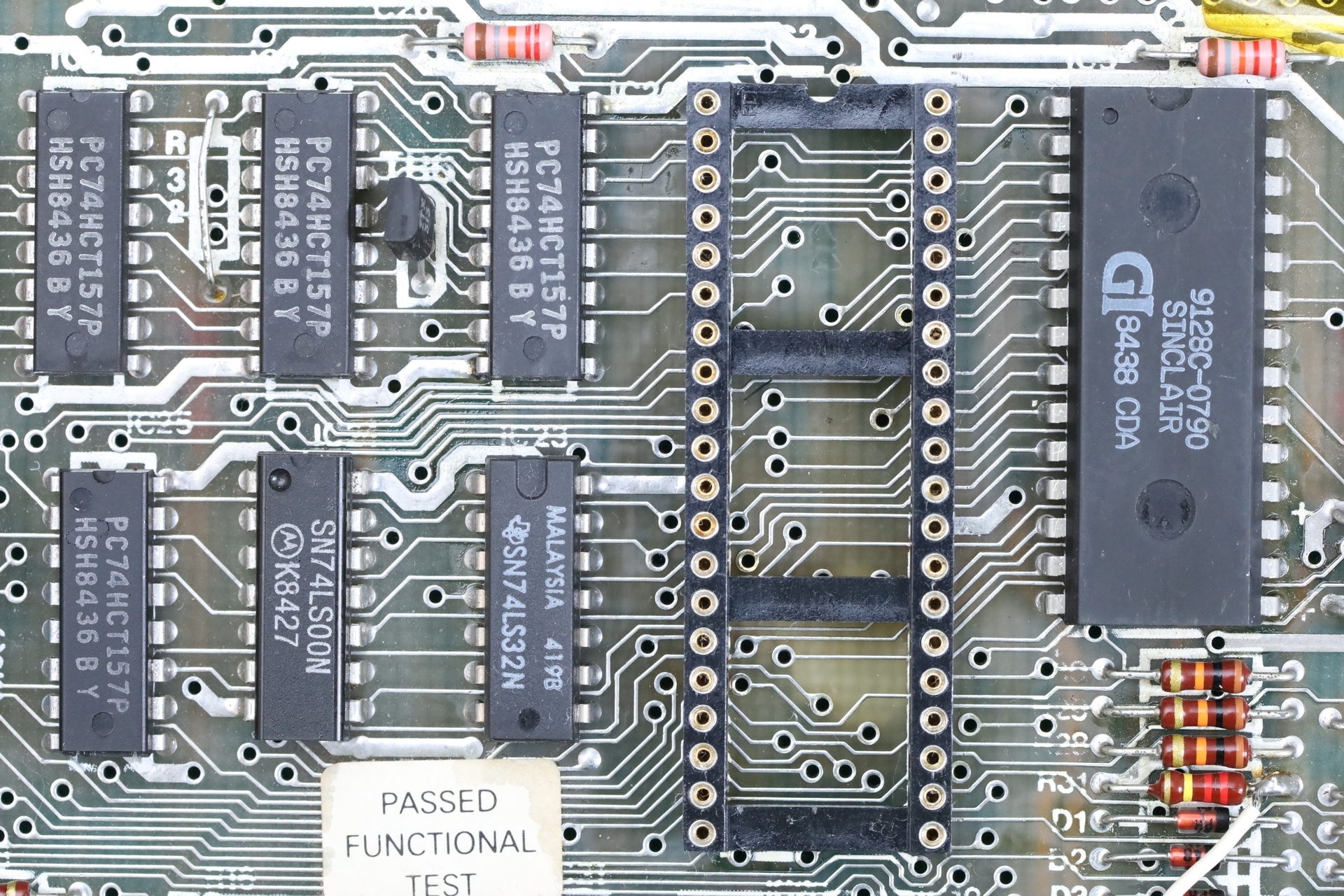
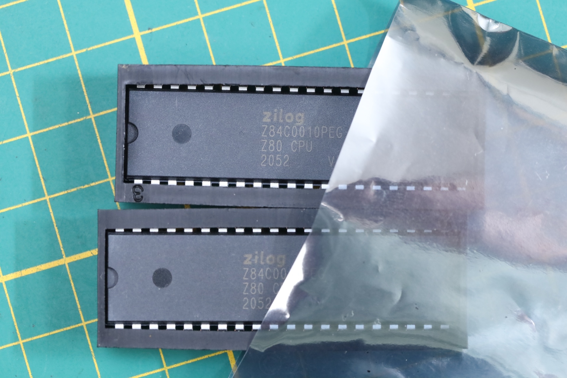
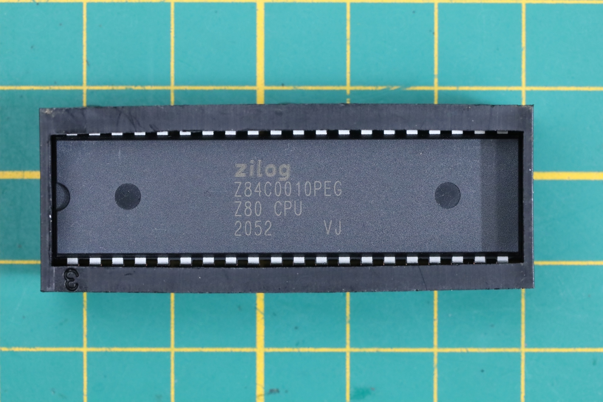
This fixed the board :)! The choice to swap the CPU turned out to be the good one.
Results
With D15 and the CPU replaced, the board is now running fine. No more erratic boots, smaller current consumption due to newer technology CPU and stable operation. TR7 is also cold.
The A10 Address line looks fine on the oscilloscope:
In conclusion, I had to swap the D15 and the CPU to get the situation under control, while learning some new things about the Sinclair Spectrum.
Very weird the way the D15 (BA157) failed. With a simple diode check on the meter, it tests fine. Without that clear message in the repair manual, it would have taken a lot of trial and errors to get to it. I don’t understand the DC-DC circuit and I am impressed how somebody could have figured this out, especially when D15 is not in a direct circuit with R79 ?
The CPU failure was also weird. It mostly worked in the beginning, but then it just stopped working, executing few instructions and freezing the whole system.
I have now put back the old ULA. The only sad thing is that I had the heat gun temperature set too high. The board is now slightly darker under the CPU, where I had to heat up a lot to get those stubborn bits of solder to let go. I think I over heated it, but not too badly.
Few photos with the end result:
I have ordered few more boards, more articles to follow!
Leave a Reply