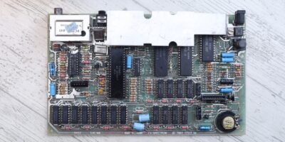
I spotted an ebay EU seller having few defective Sinclair Spectrum motherboards up for sale. And not long after, I had the three sick motherboards in front of me. This is the story of salvaging one of them.
They came like this:
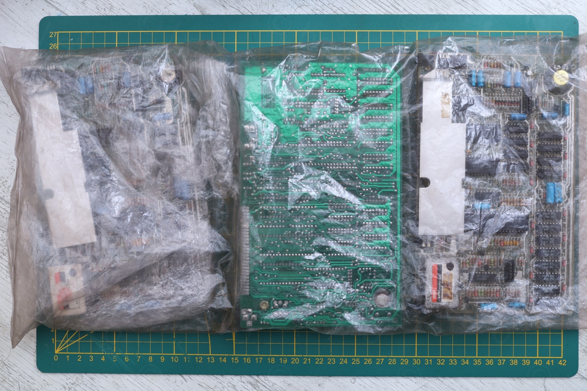
Table of Contents
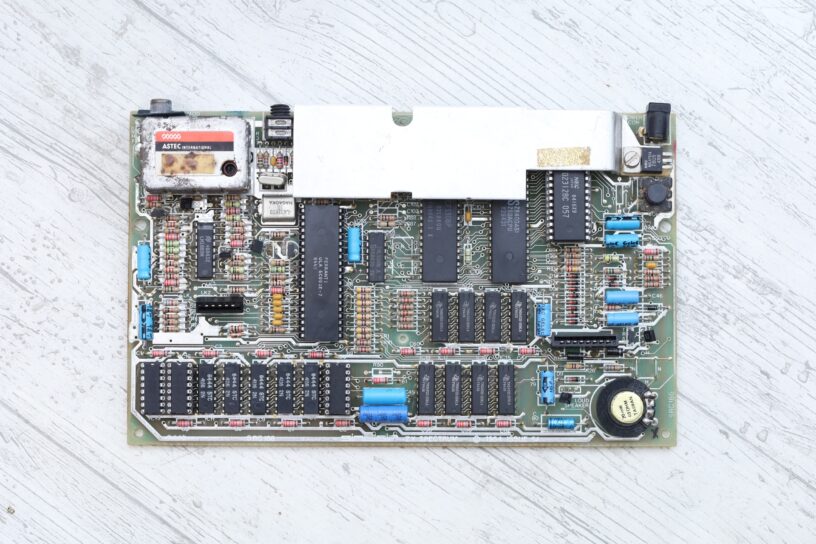
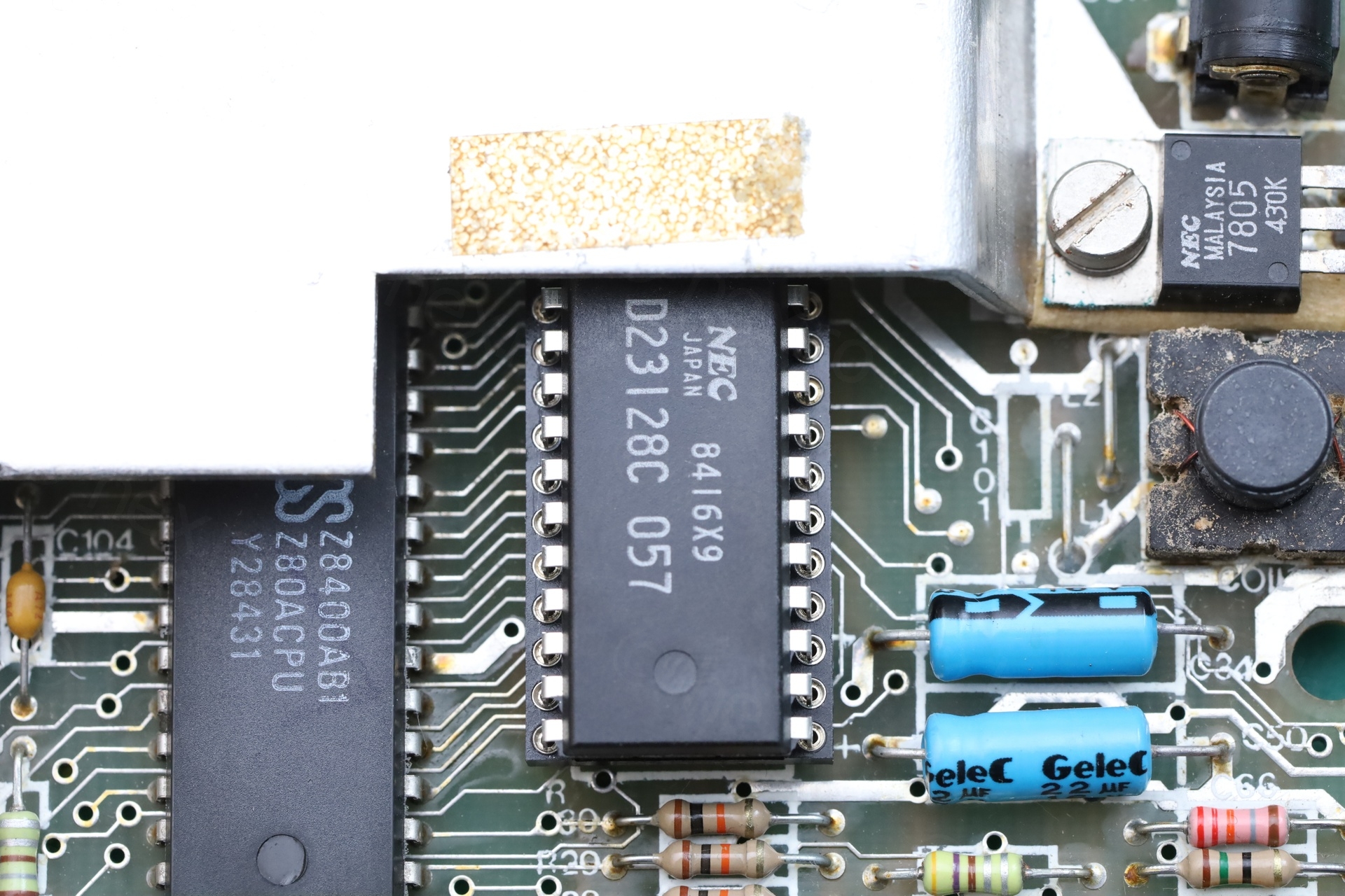
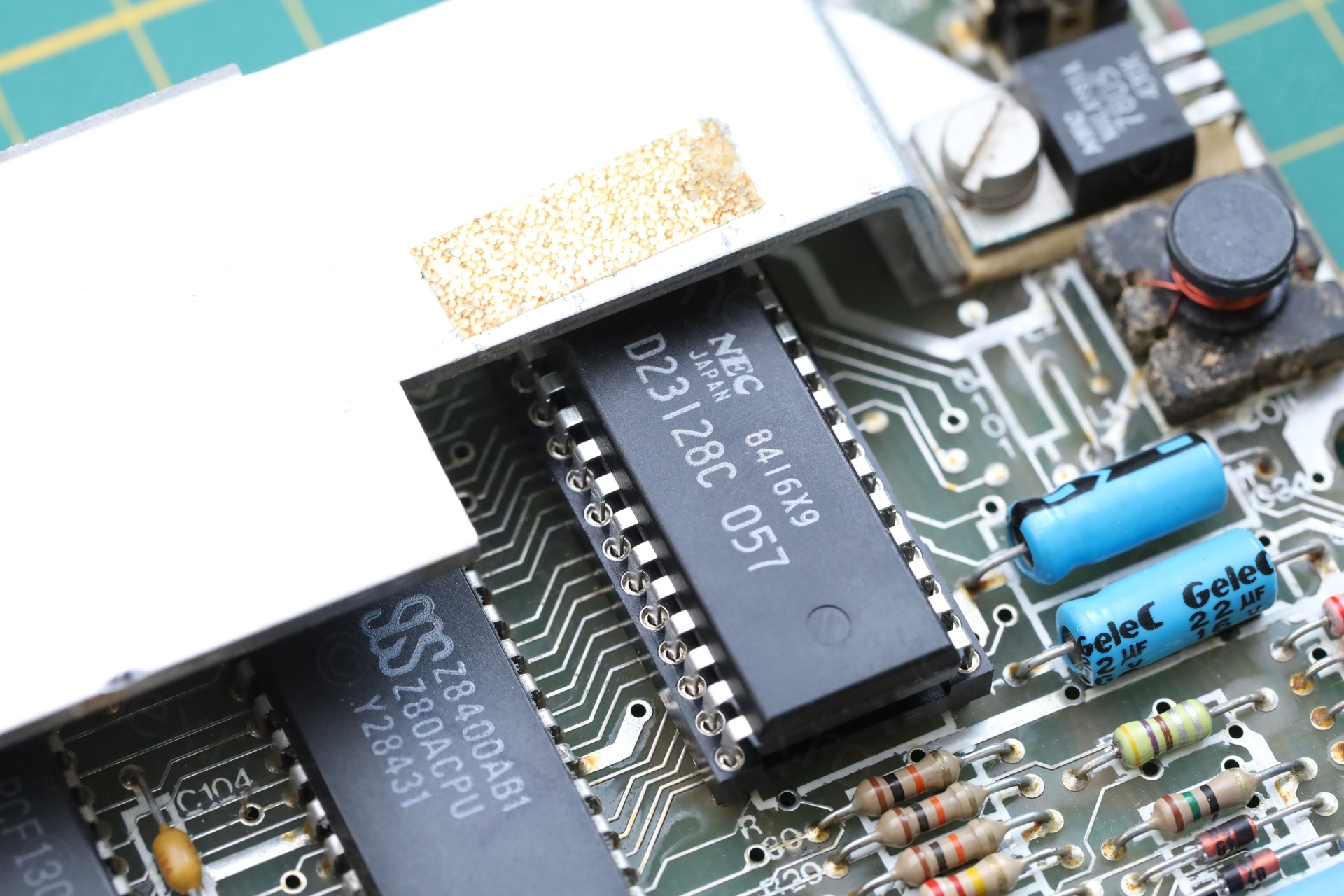
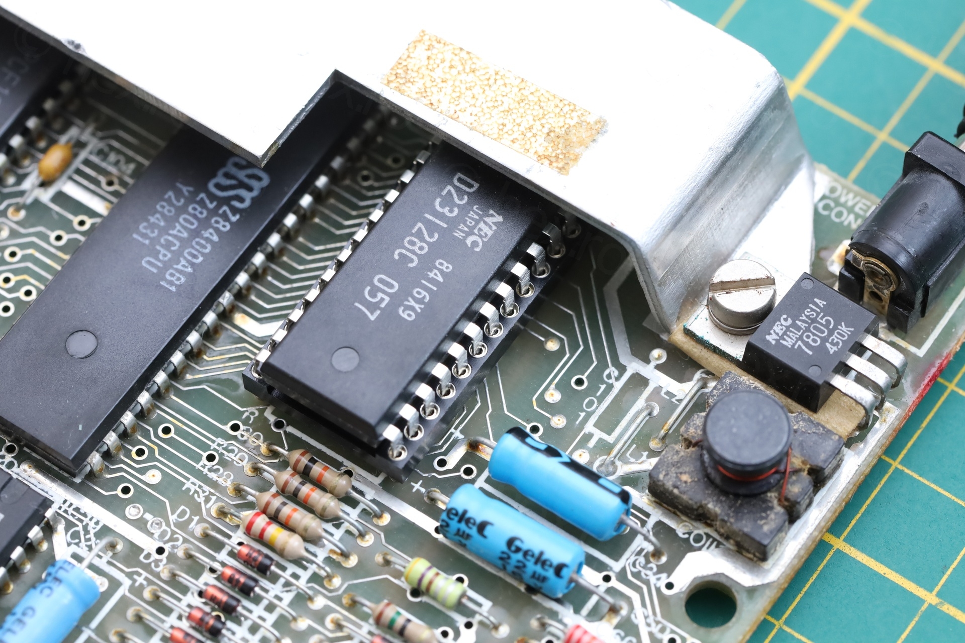
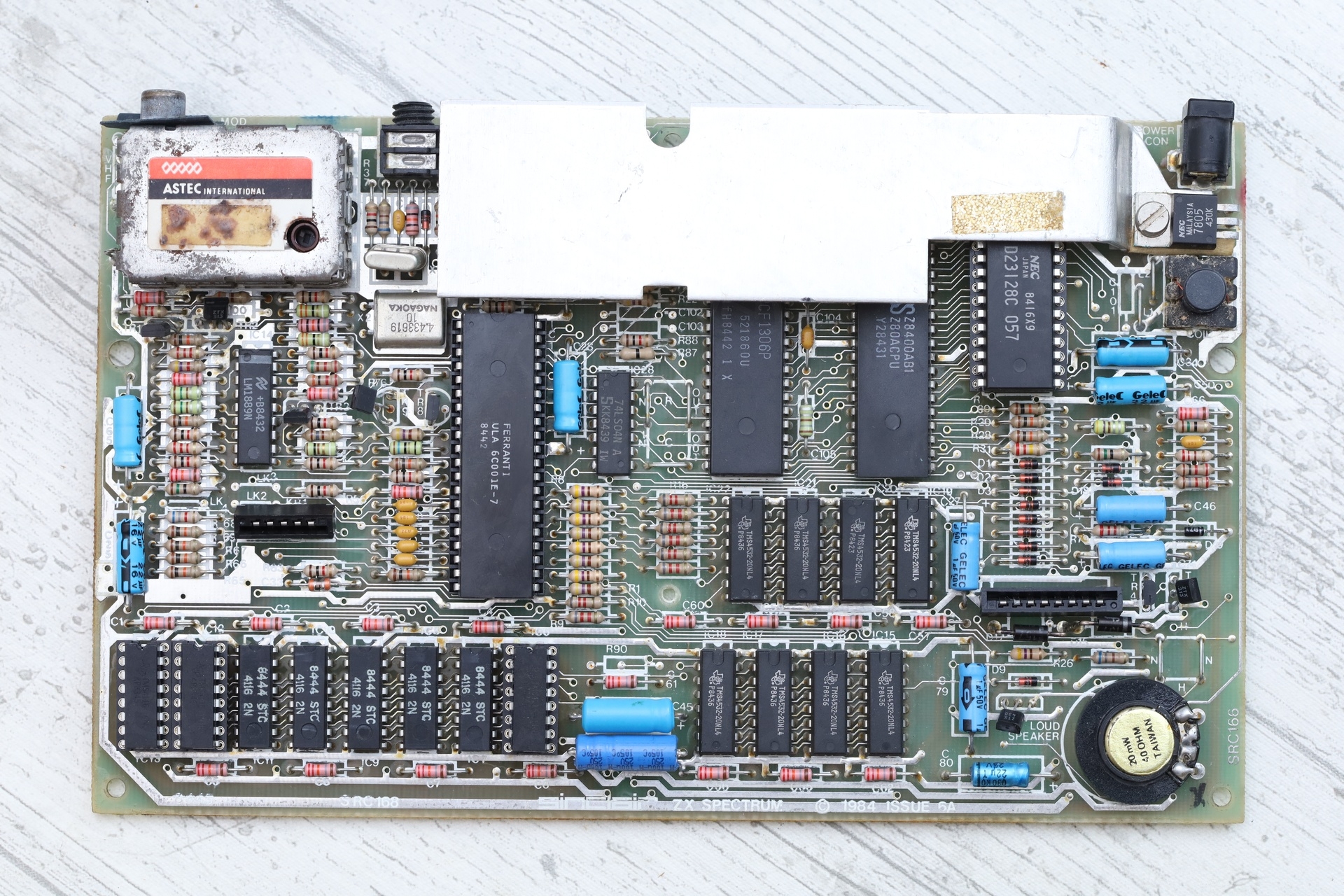
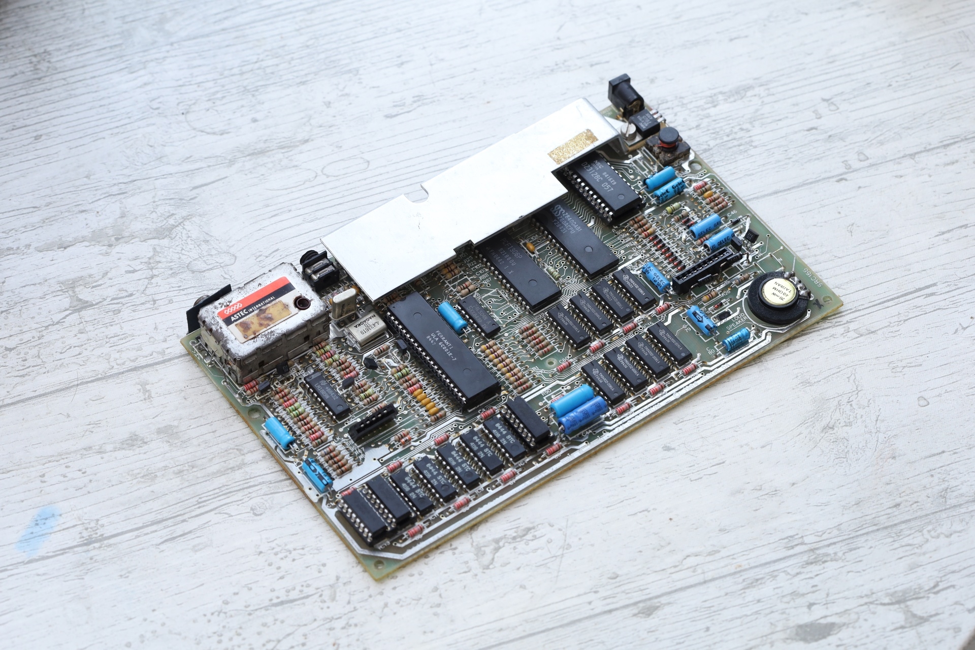
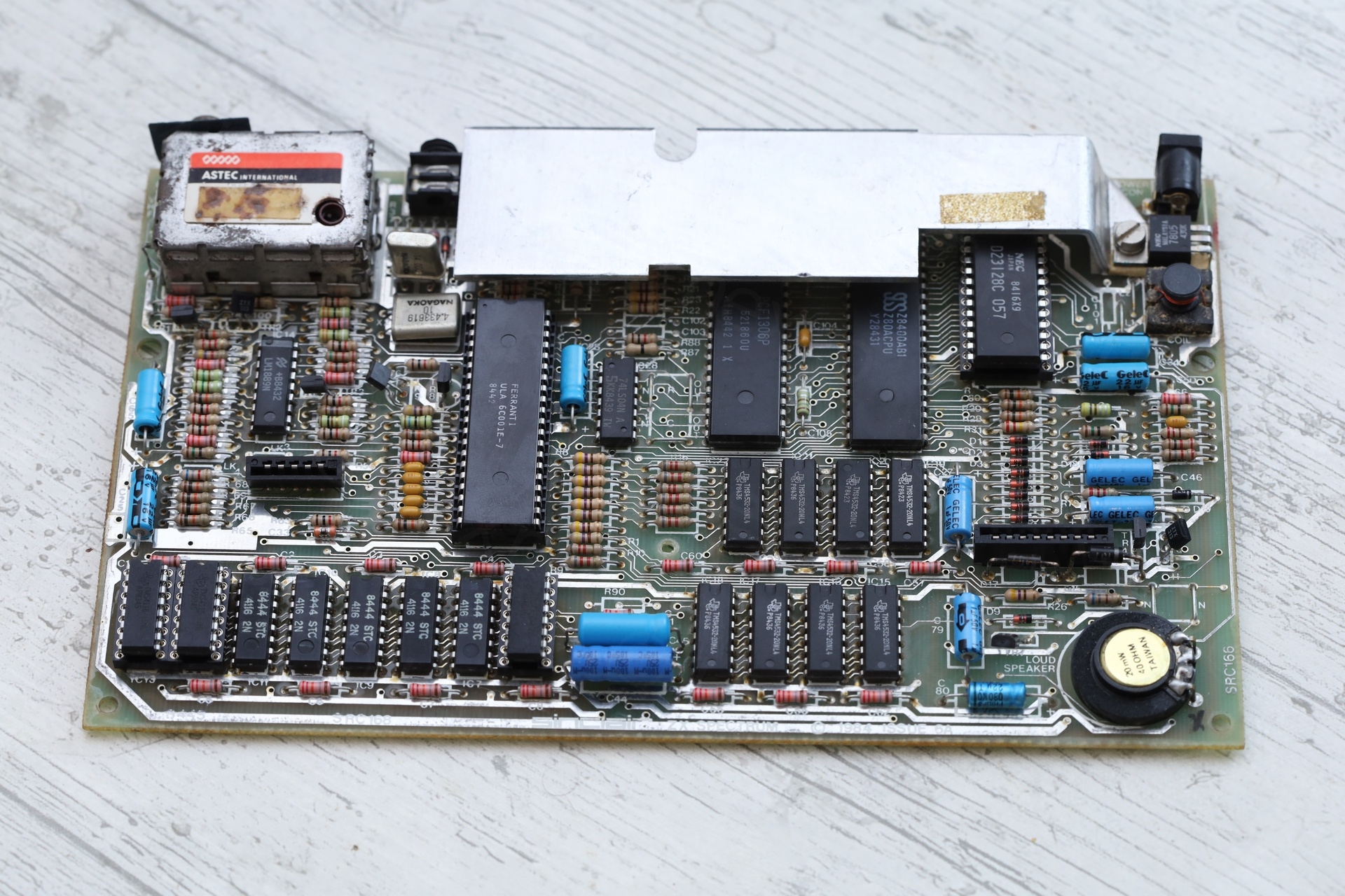
The board to check is the one on the right. An overview below:
Visual Inspection
Since the boards were listed as defective (one of them was even missing the ROM chip), I figured these are failed attempts and somebody has already powered them. Freedom to skip pre-checks! As if there’s anything that could blow by applying power, it already did.
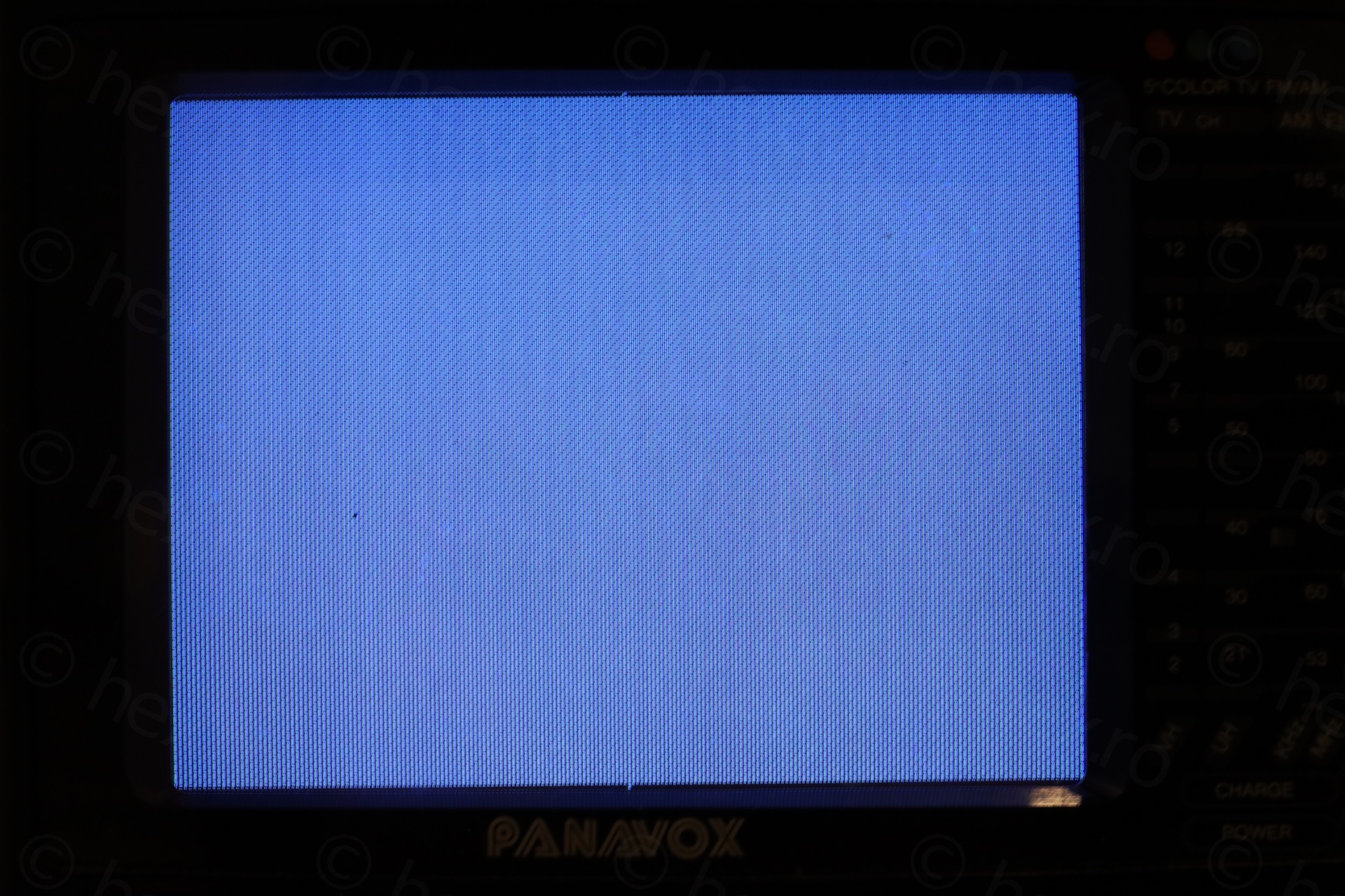
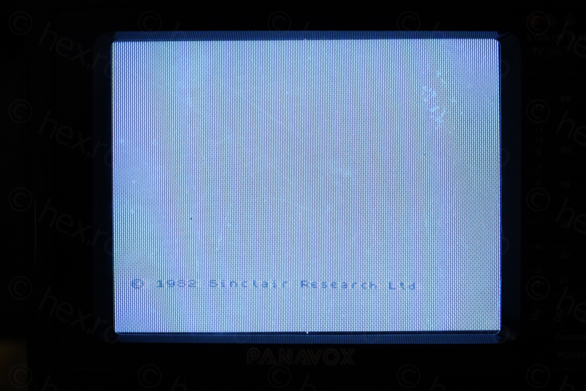
And … it doesn’t work – screen is black and ROM chip gets hot very quickly:
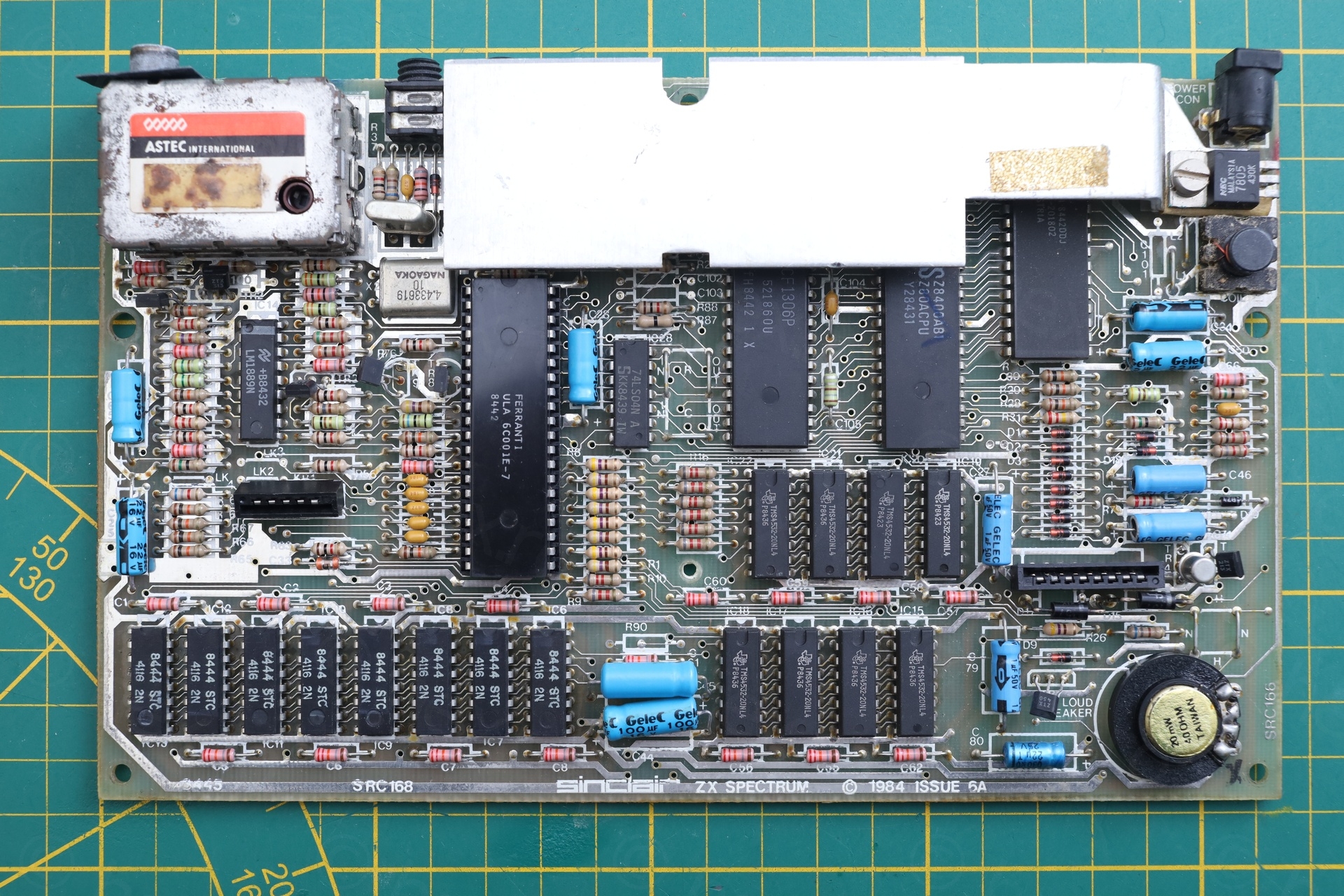
Let’s see what was touched on the board.
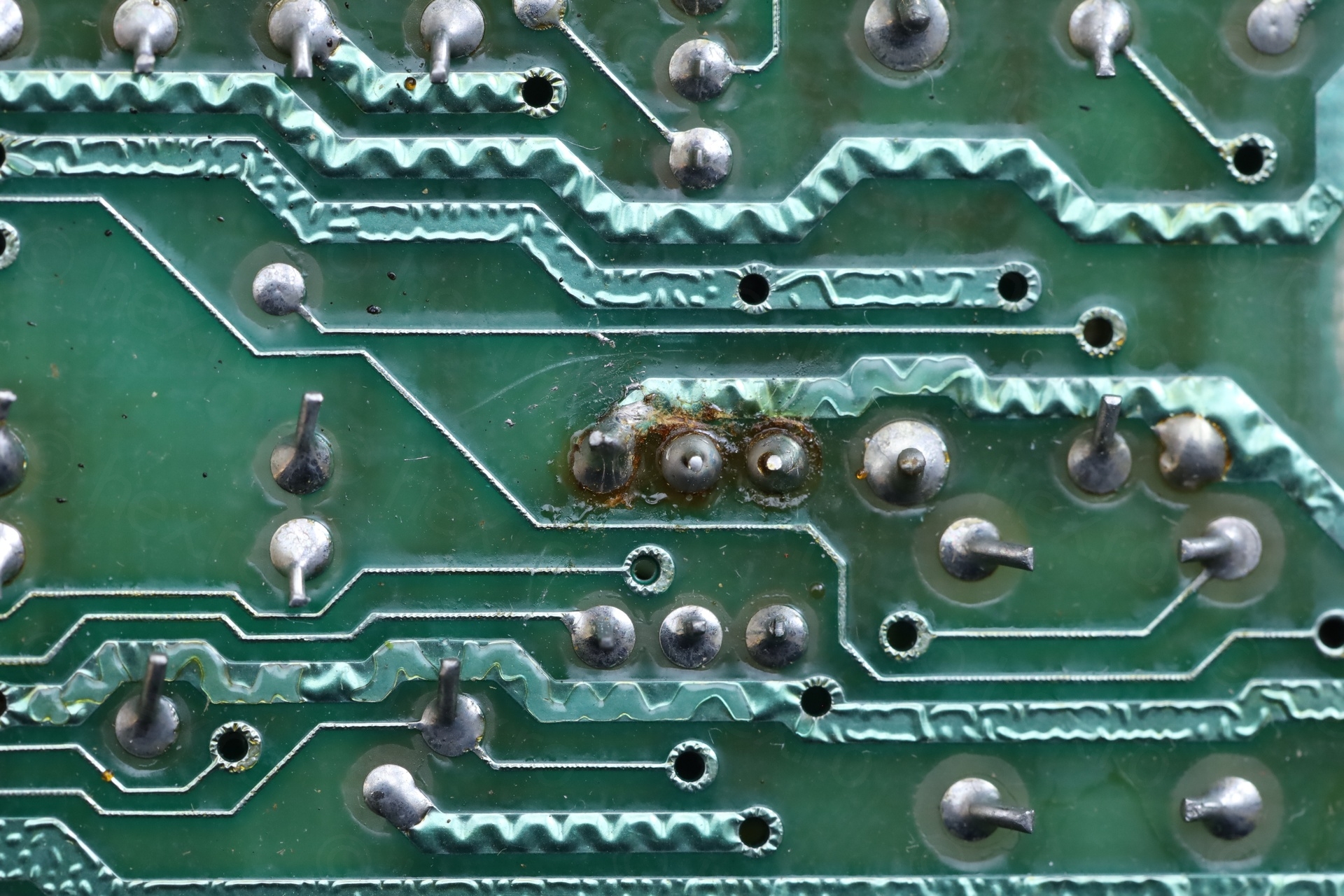
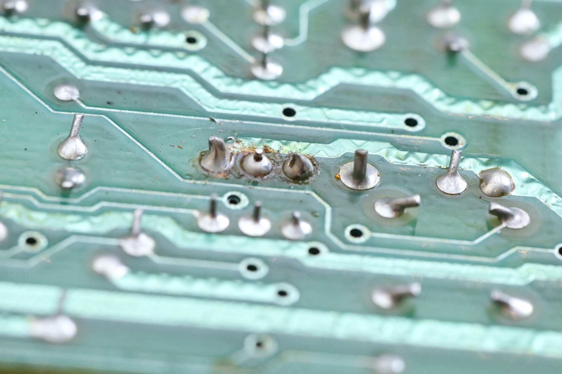
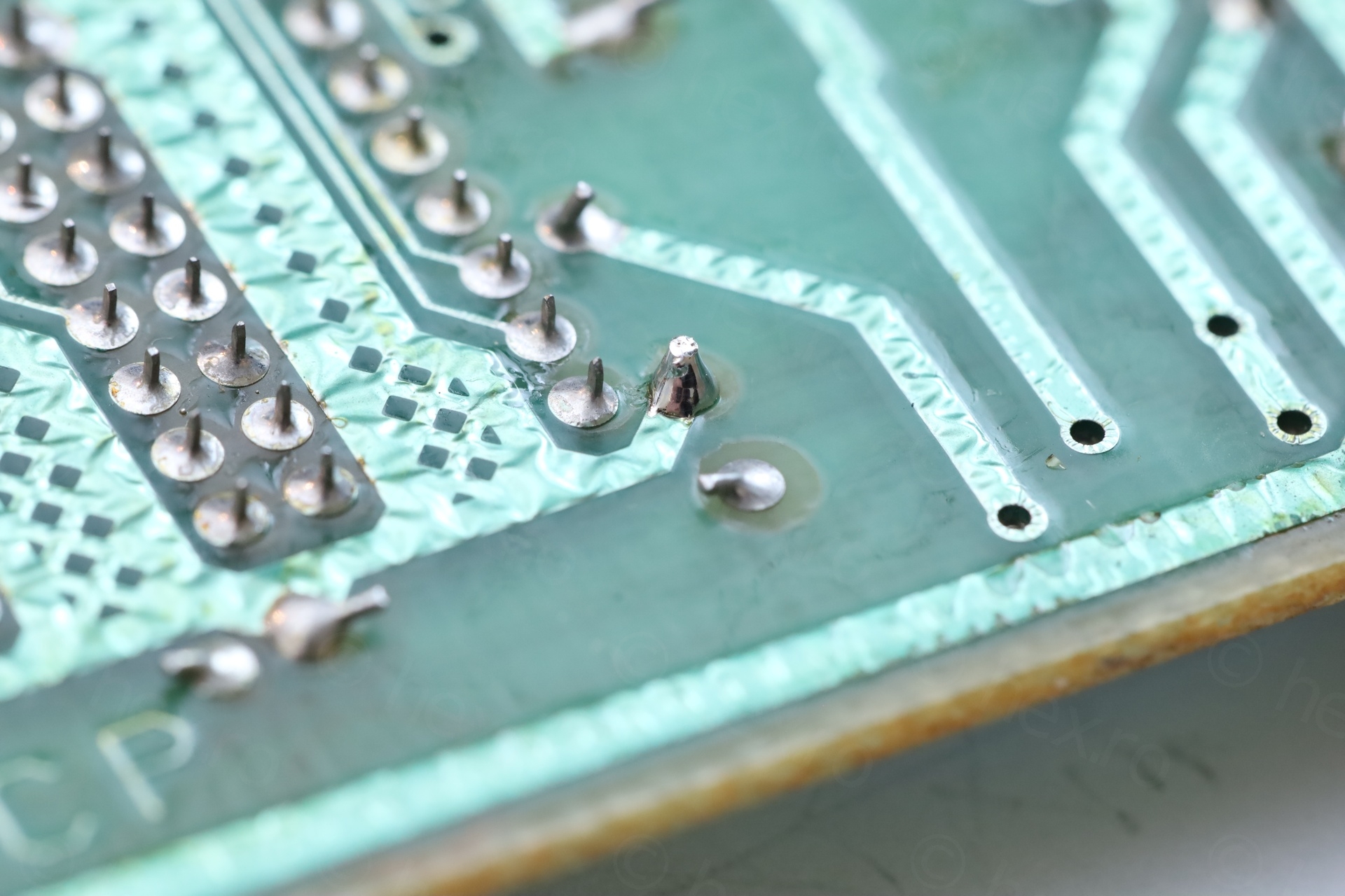
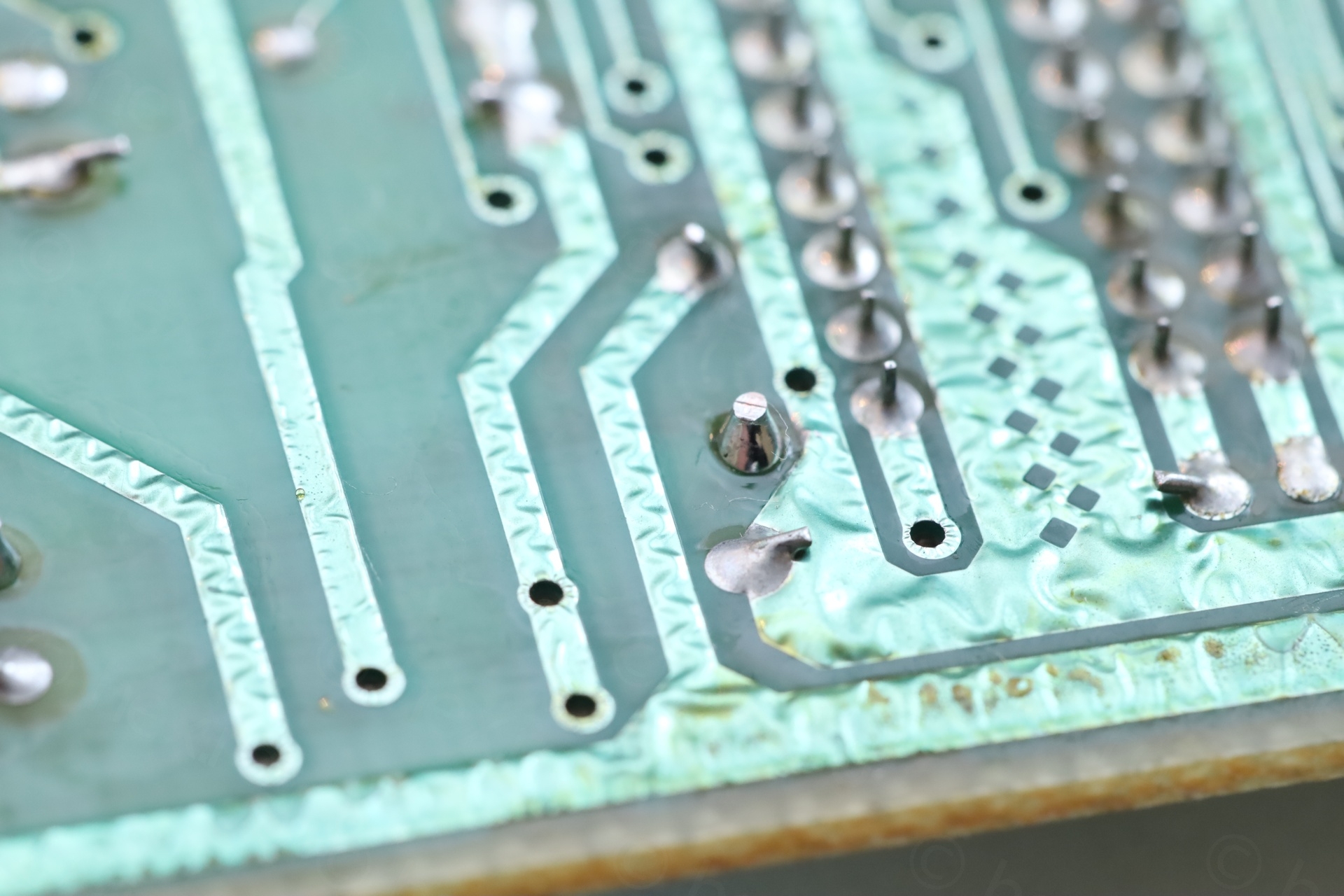
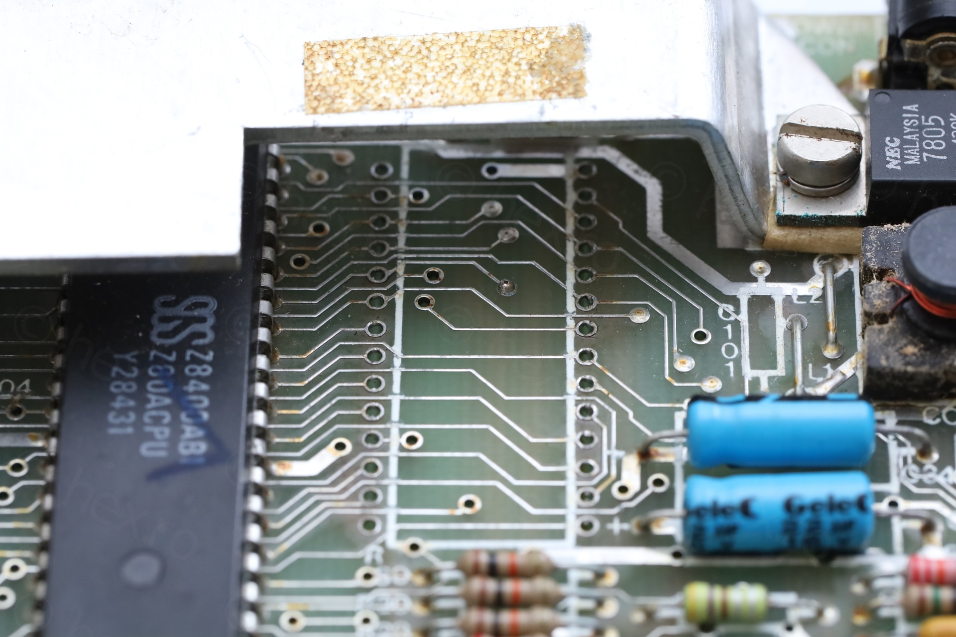
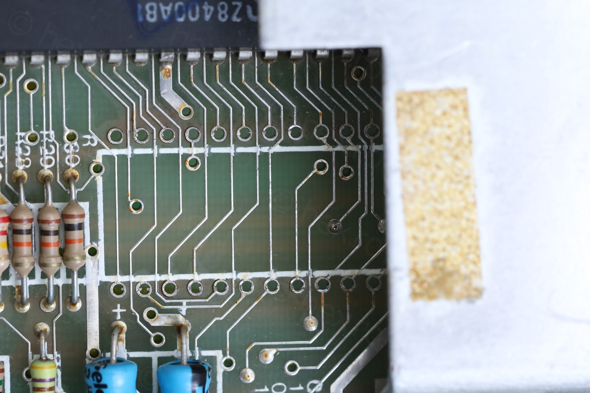
RF Modulator is disconnected
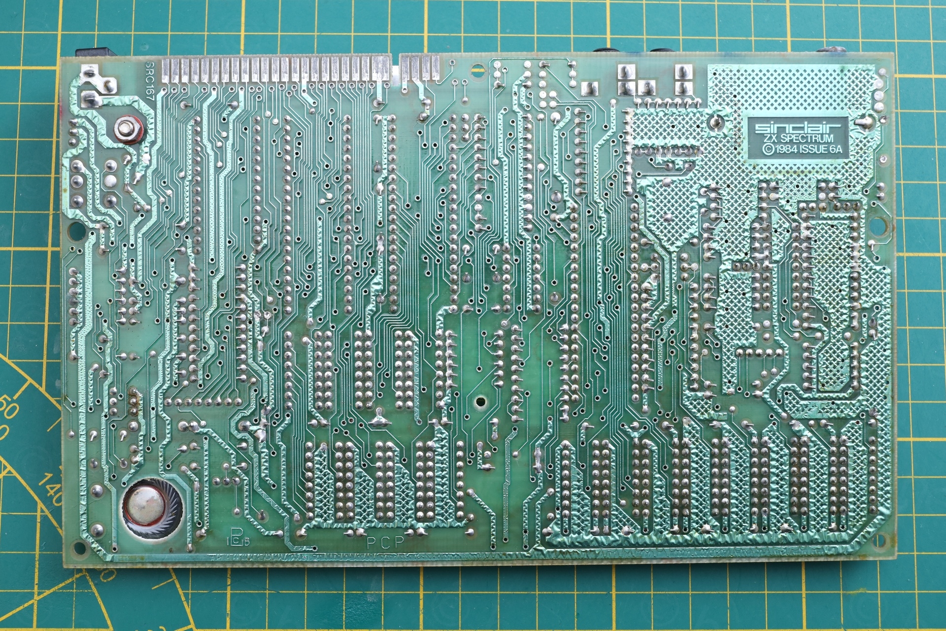
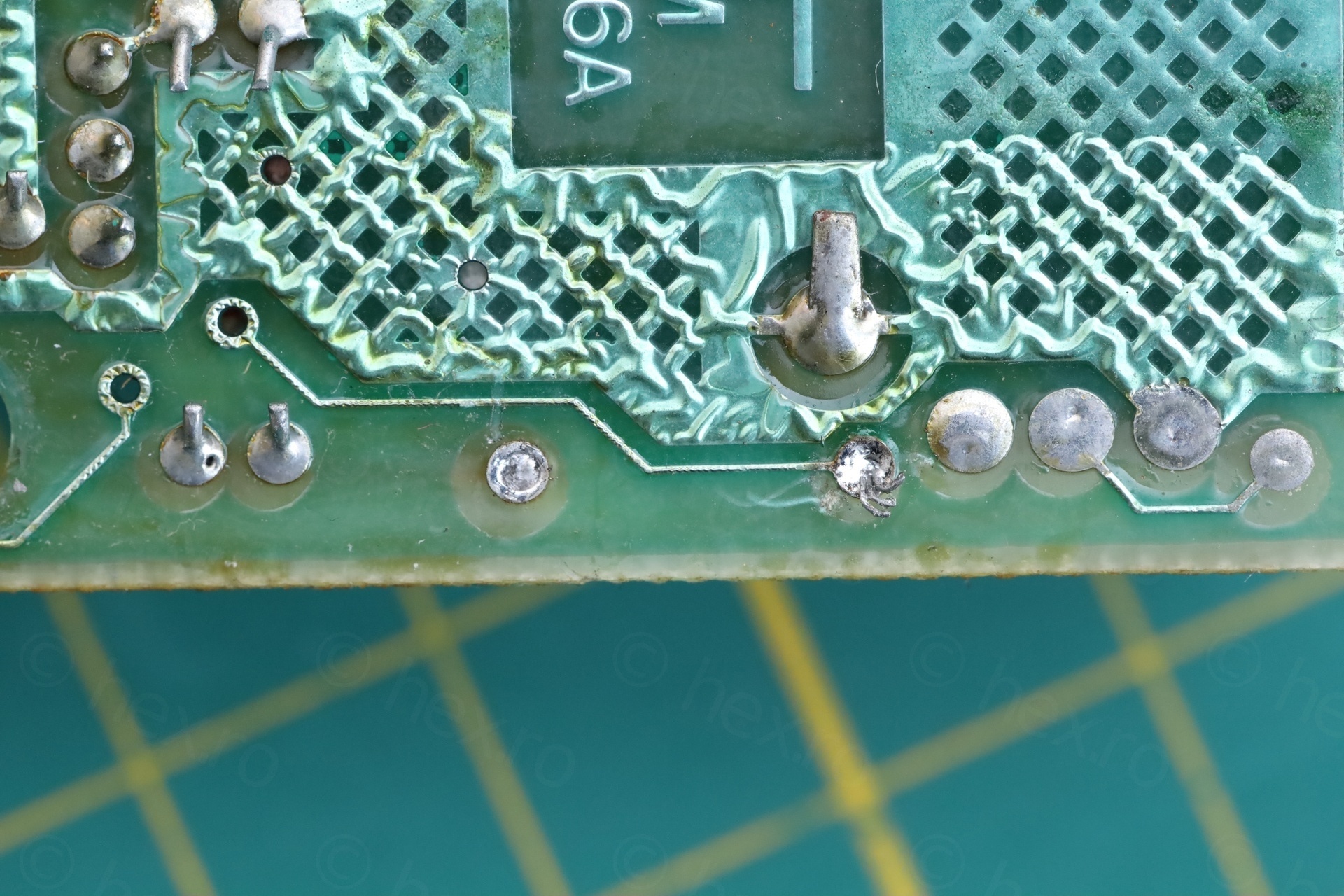
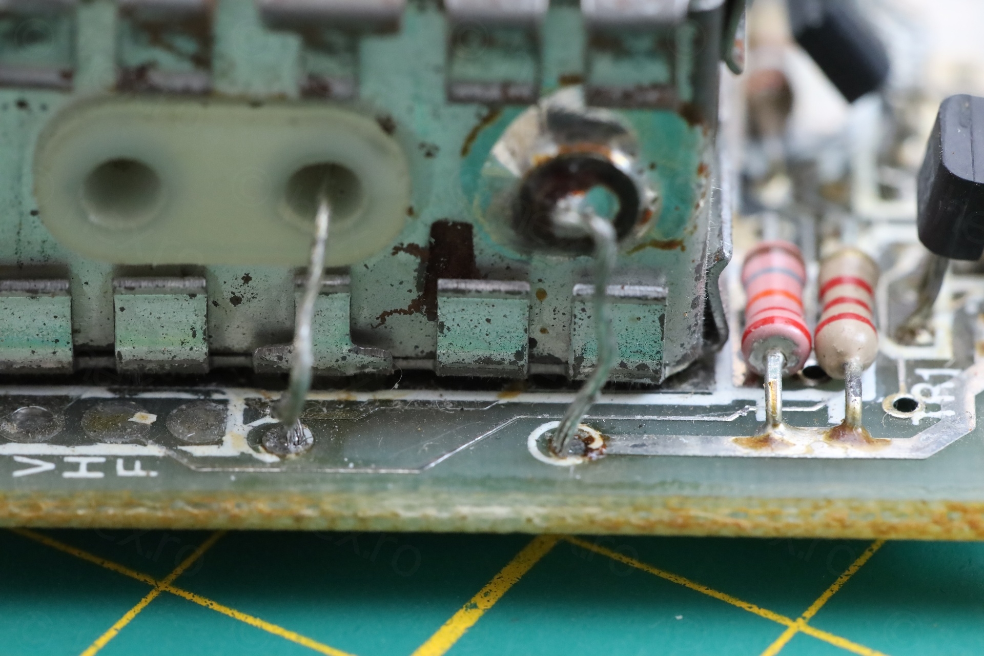
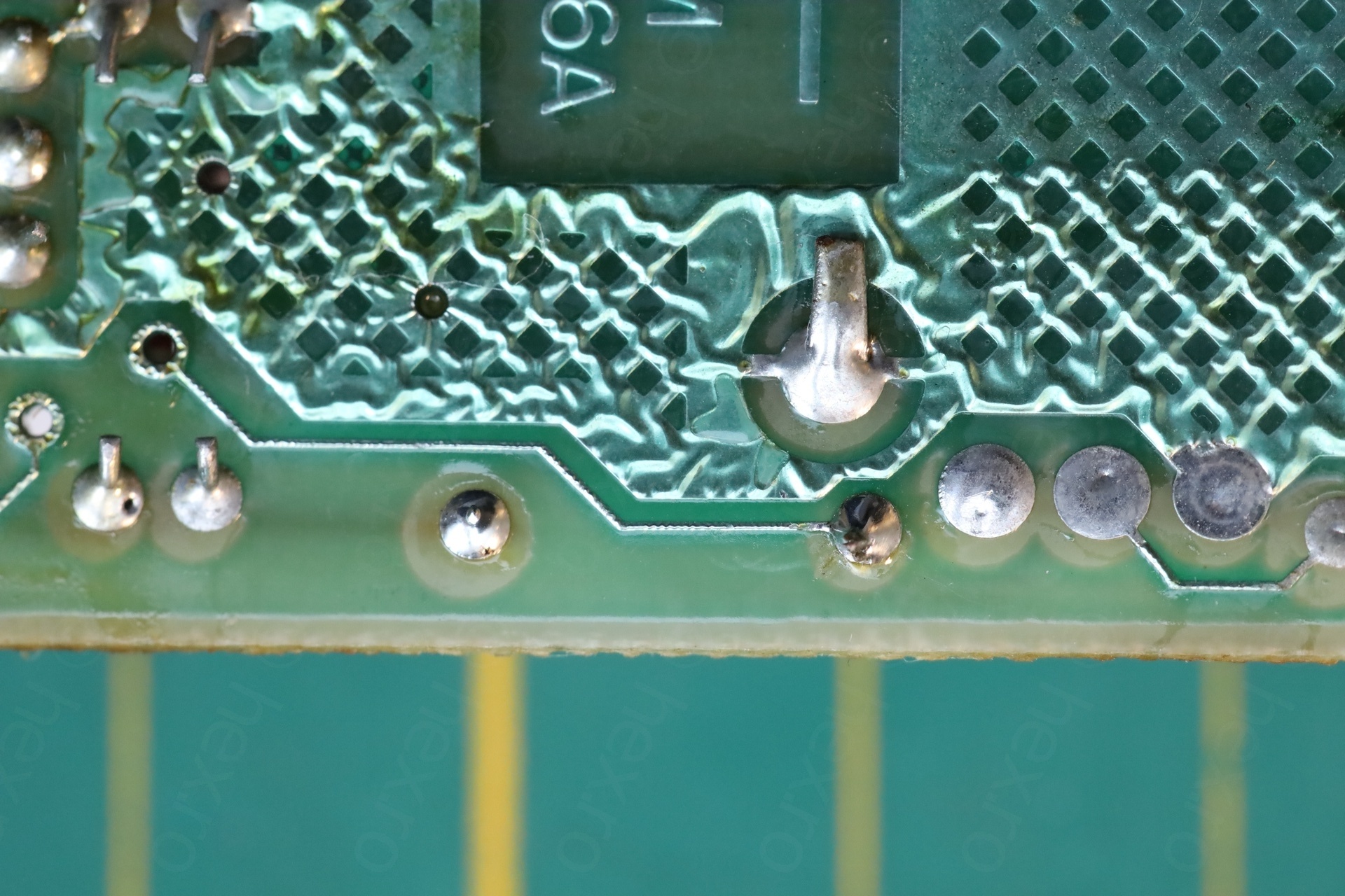
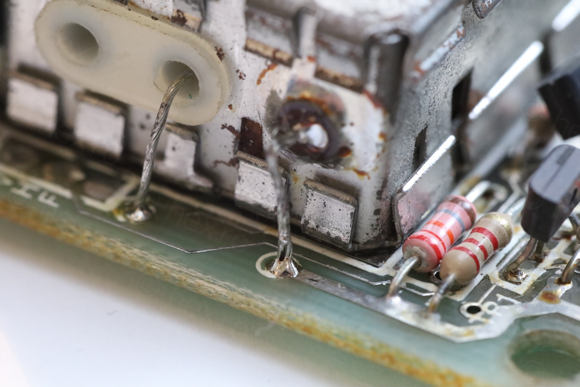
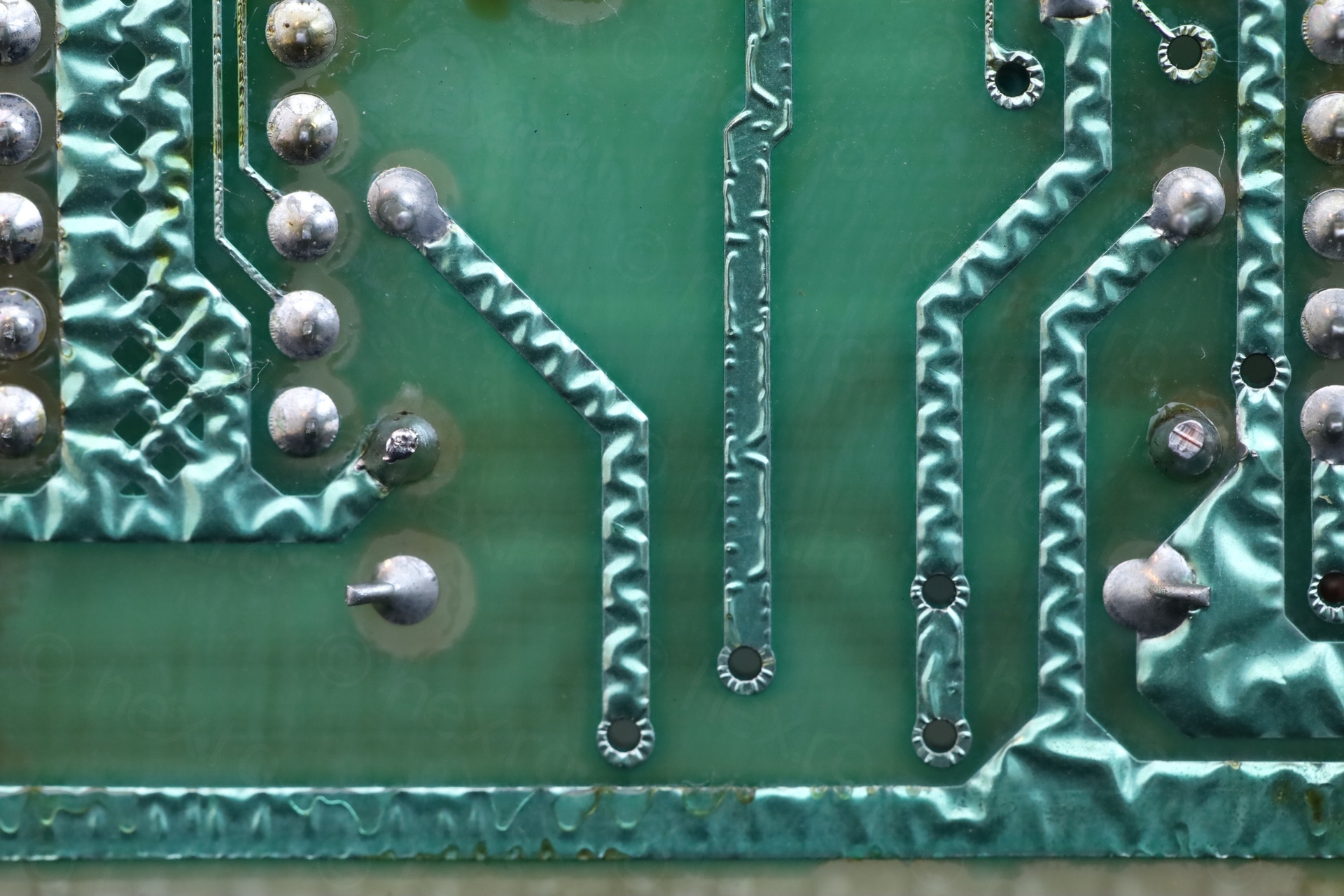
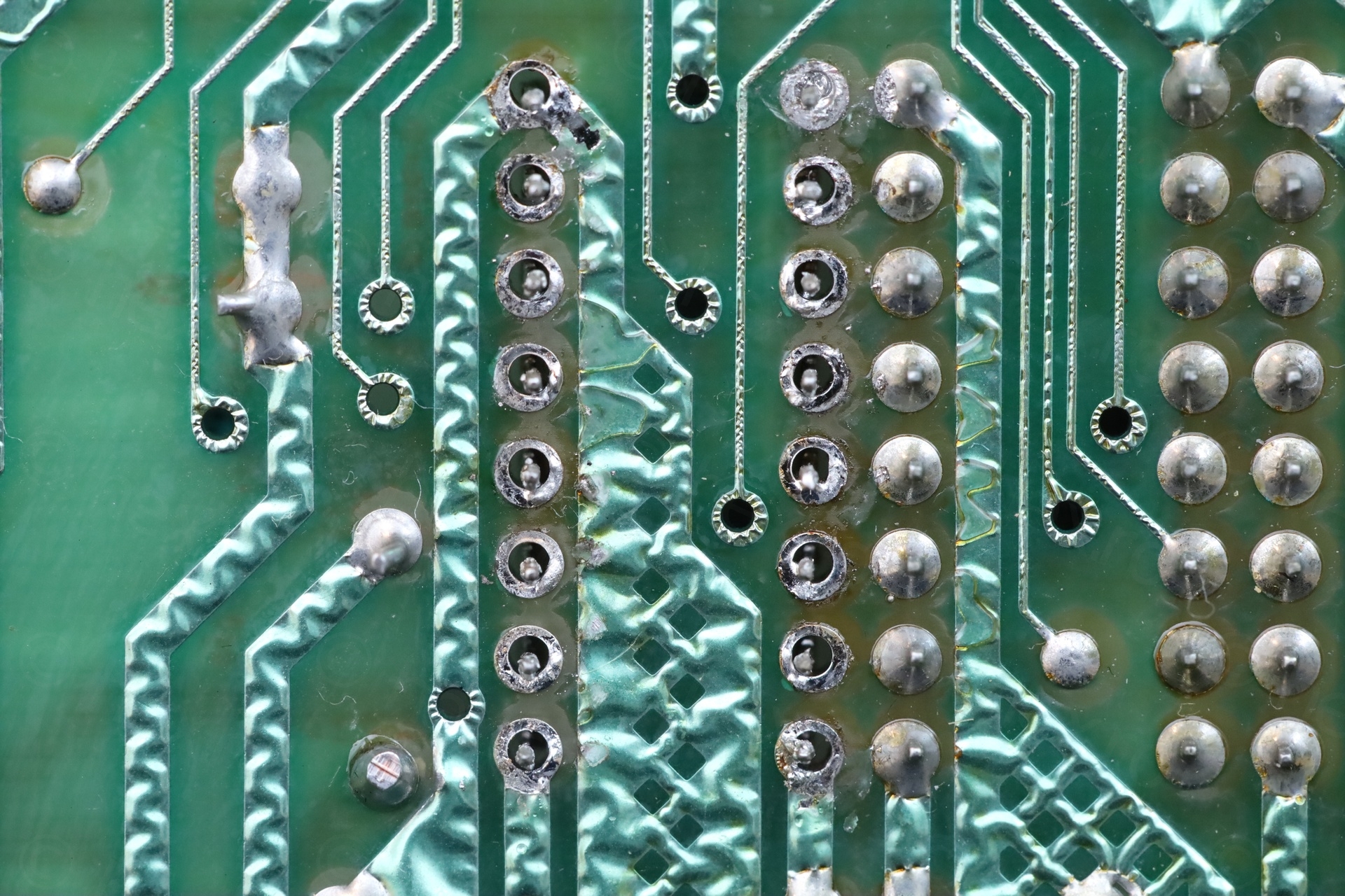
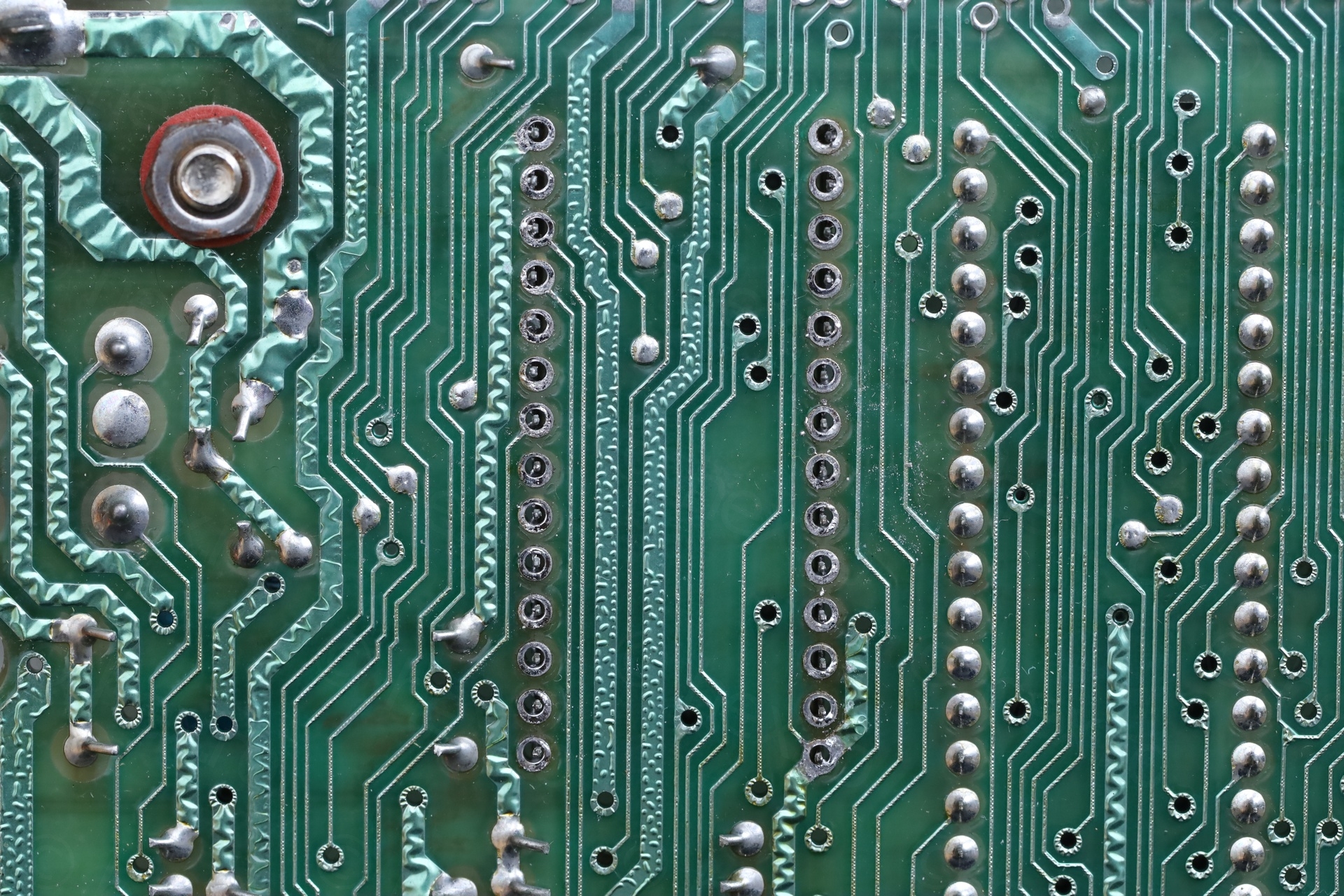
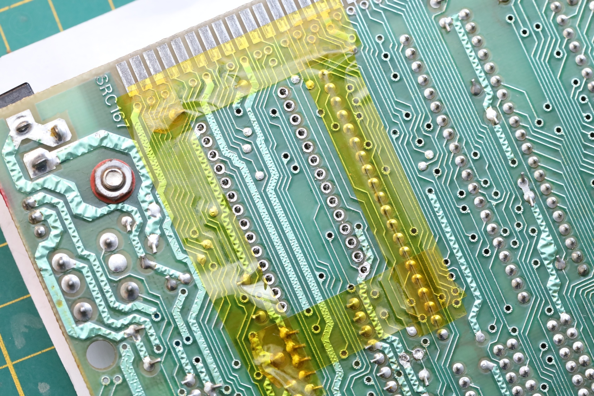
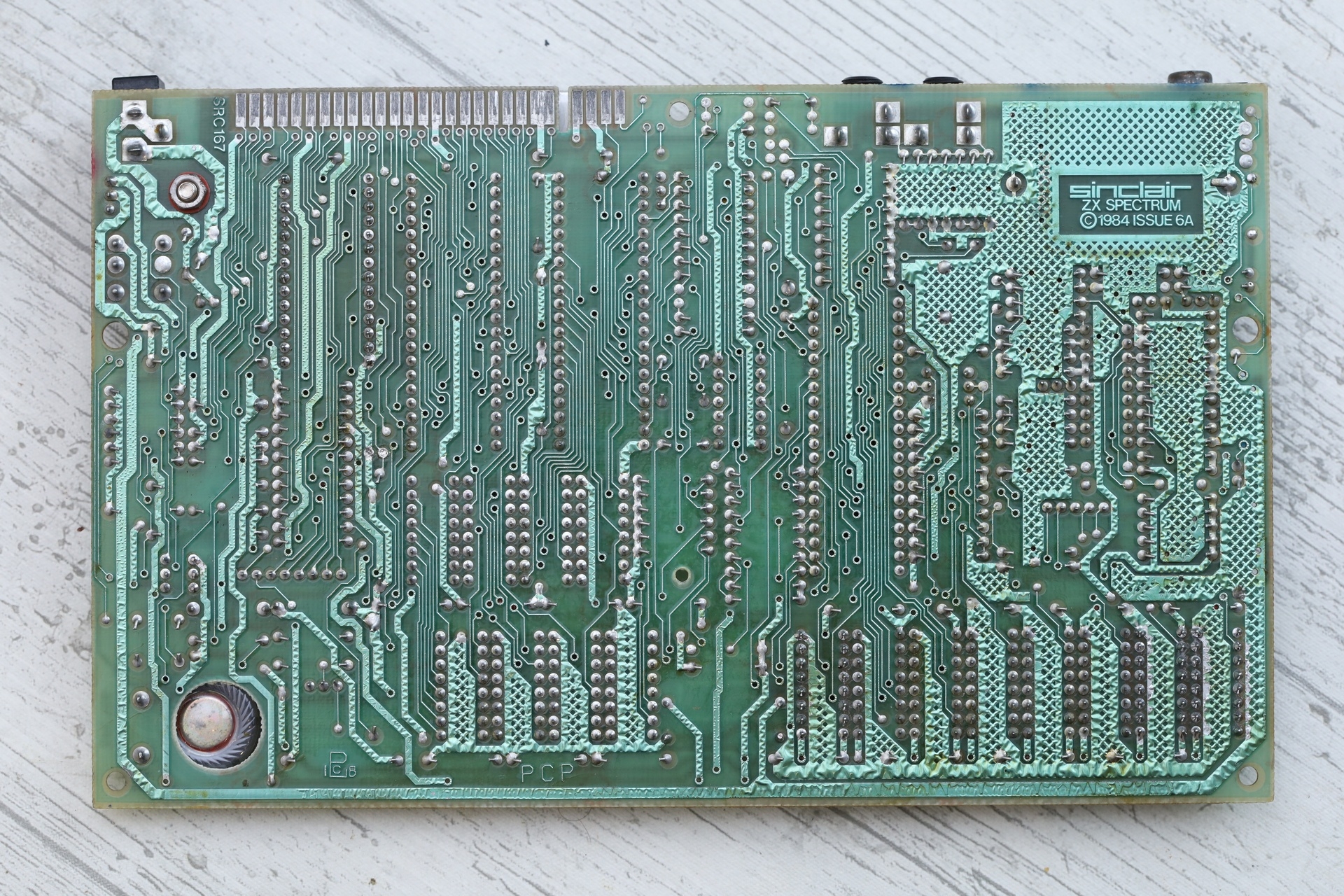
Although I didn’t notice it first, while checking the beautiful Sinclair logo on the back of the board, I spotted missing solder on the two connections going to the RF Modulator. And looking closer, the RF Modulator connections were severed at the board level:
RF Modulator – Severed connections
Was this a botched Composite Video Mod ?
I appreciate that the video mod exists and people were smart enough to figure it out. It has its use. But If somebody wants a blocky looking Spectrum on HDMI Full HD or 4K, isn’t simpler to just use Raspberry PI and Fuse ? Old CRT TVs are affordable. Not online where sellers slap a “retrogaming” tag and ask 10 times more. But if one would take a stroll on the local flea market ?
And I don’t understand why this mod is pushed so much. Almost all Youtube channels show this mod off. Almost all pages mention it as a revelation. Does it make for more engagement to bridge modern with old – to sell it as, oh, let me open your eyes on what you have been missing so far, this is amazing ? While butchering these historical boards ?
I am not doing the Composite Video Mod to any of the motherboards / Spectrums. I use a simple Panavox PV-5500R portable CRT TV that I picked at the local flea market in Jeu De Balle. The picture is a little skewed, the colors bleed a bit, but it looks perfect to me. Old TVs weren’t perfect either. Manic Miner Magic.
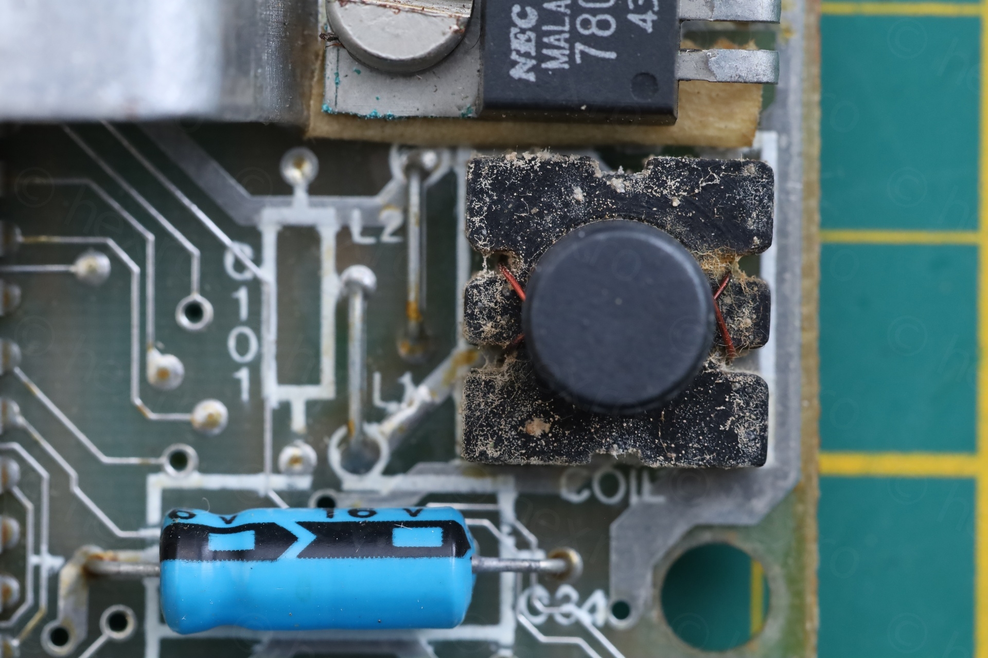
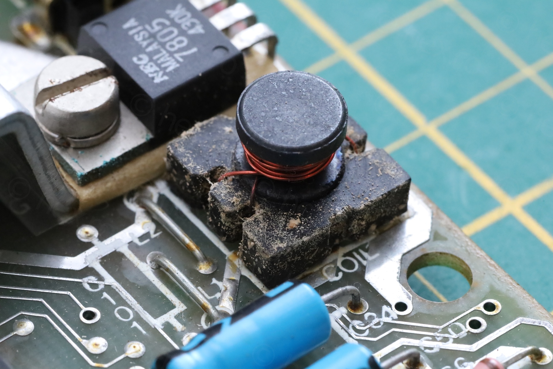
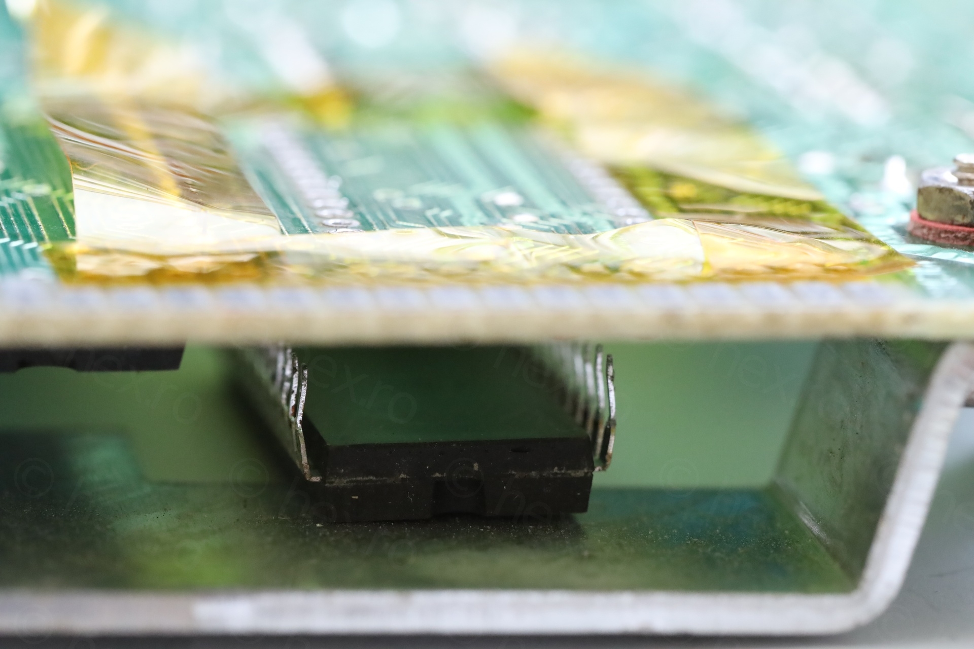
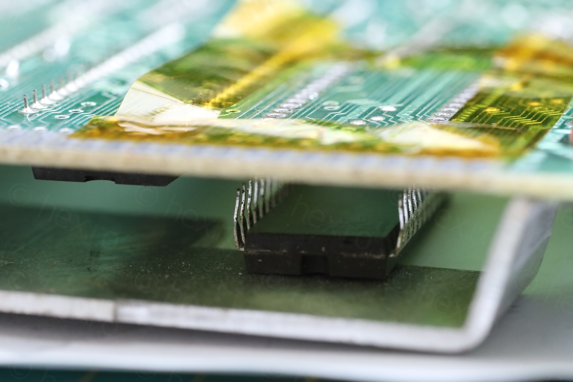
Mold on the Coil ?
Coil is good, except, I find it weird to see it dirty like this. Only the coil, nothing else around:
TR4 Transistor
The TR4 Transistor was obviously worked upon. The installed replacement for ZTX650 was something called KC 507:
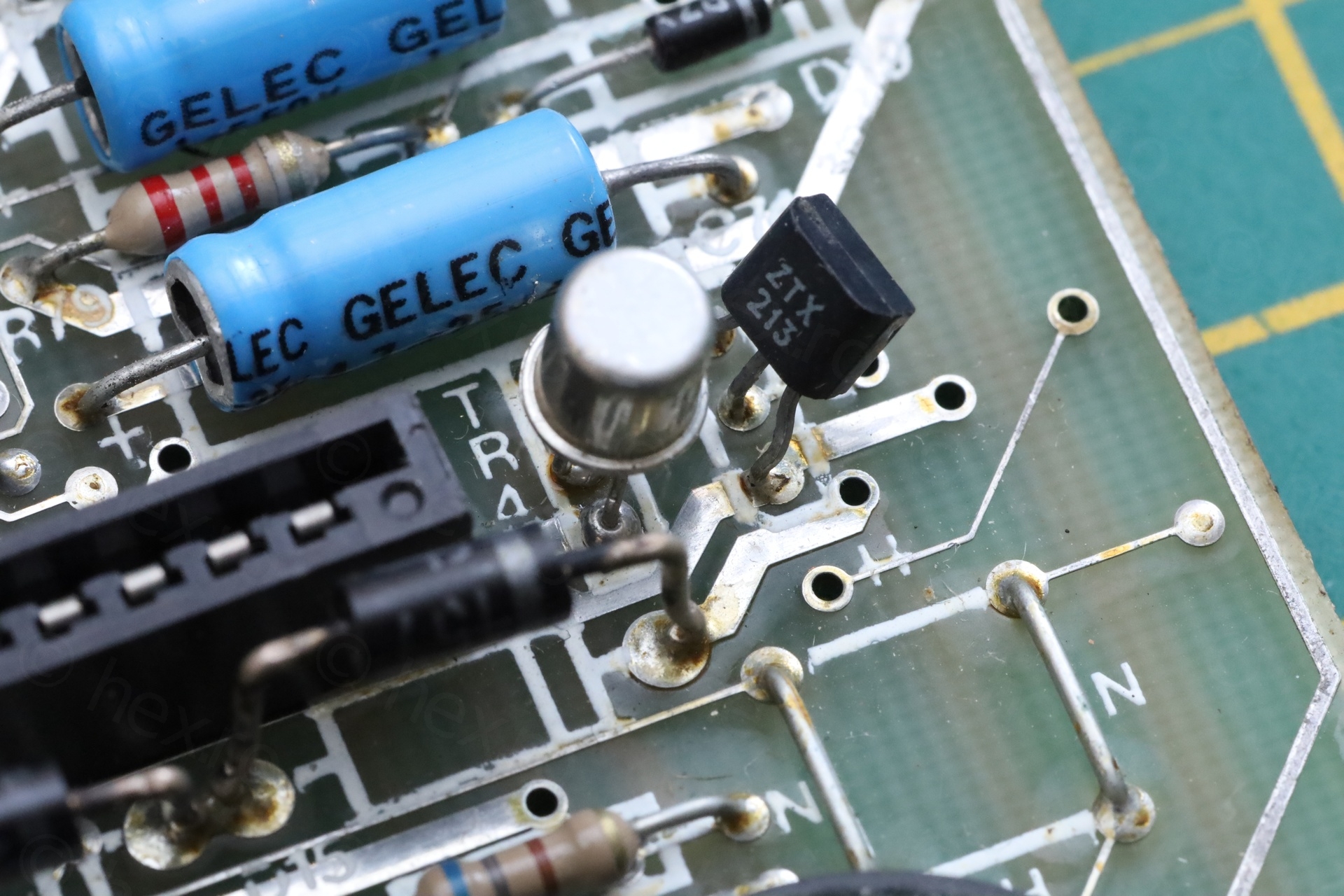
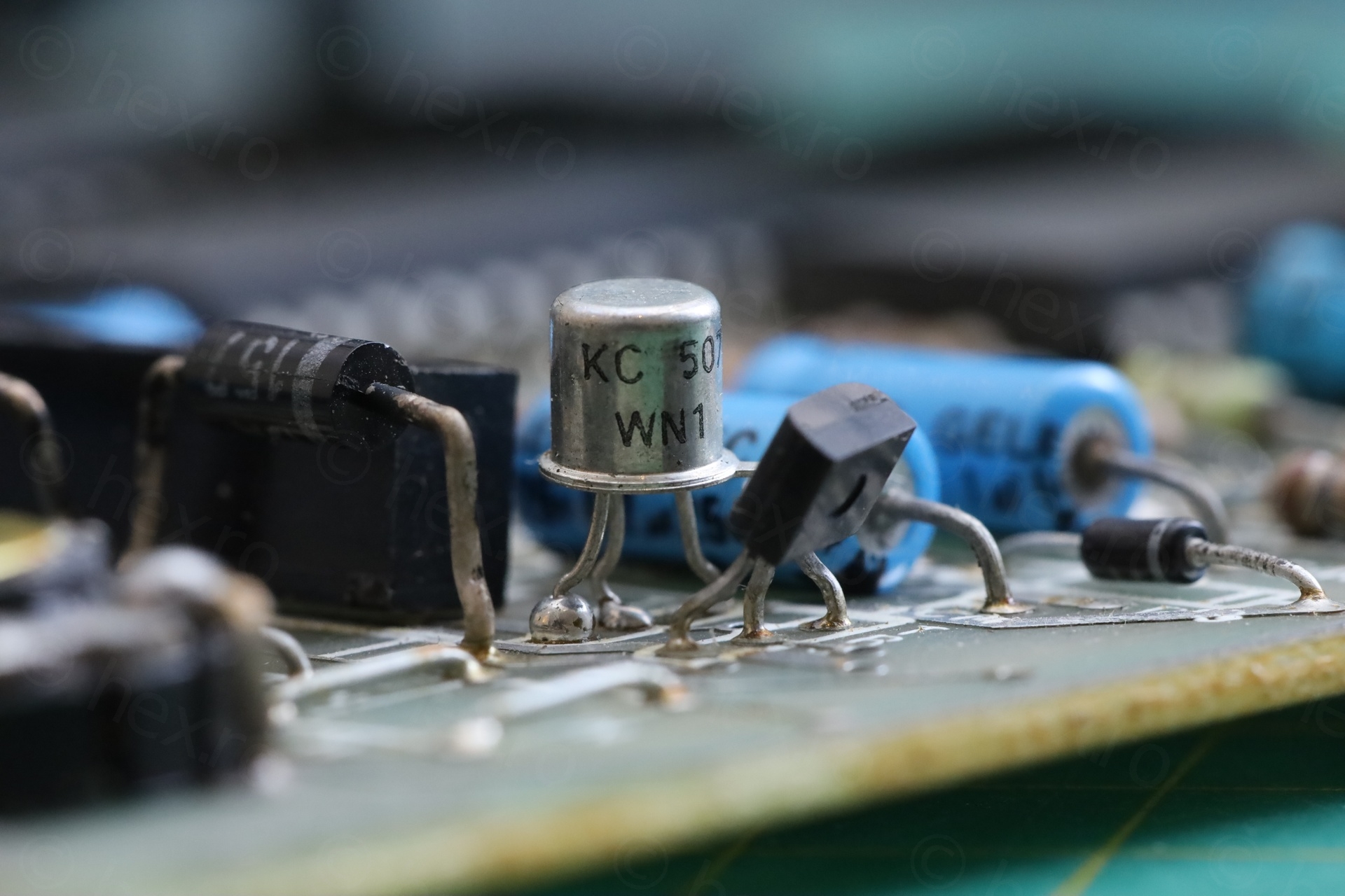
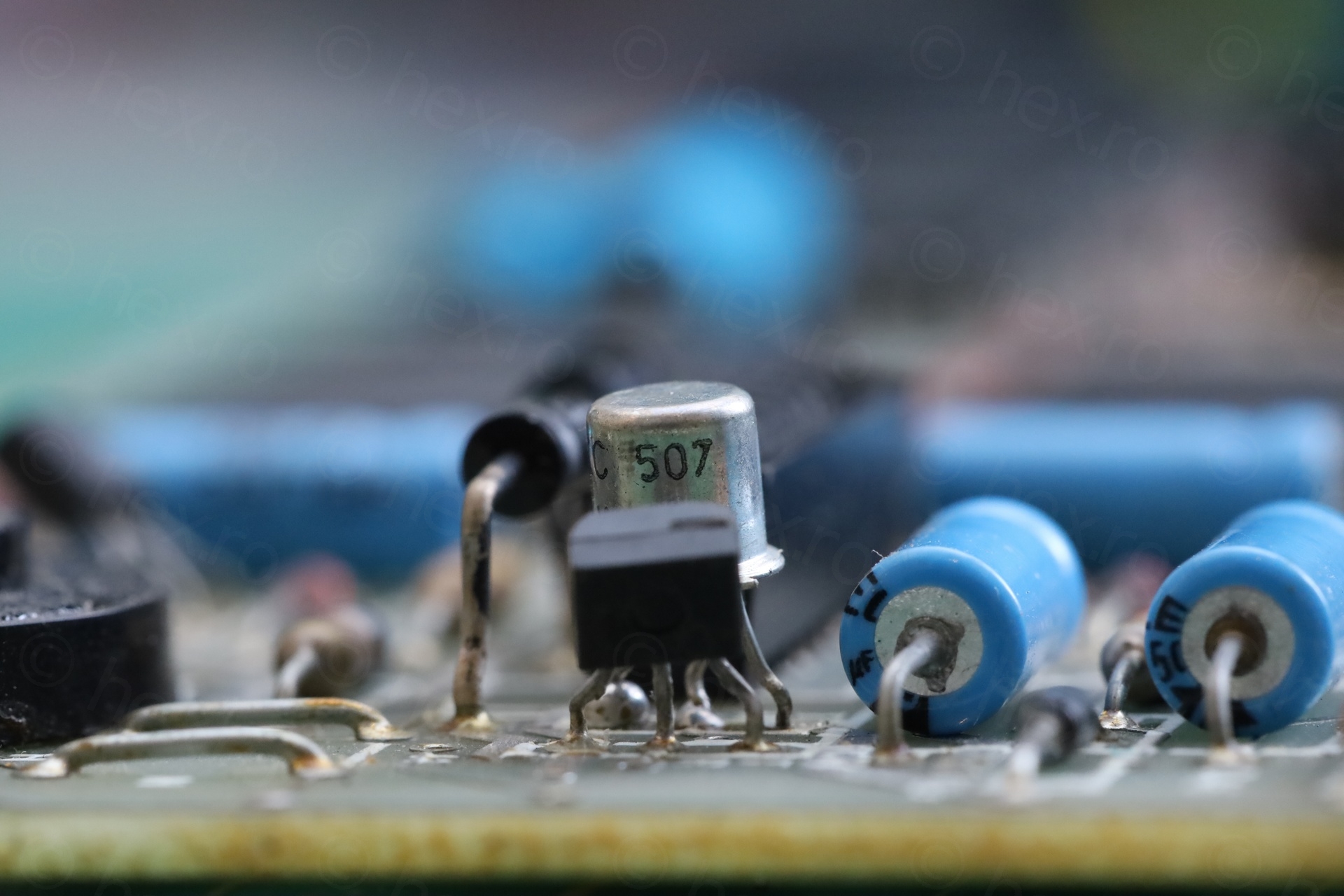
This got me curious, what is this KC 507 transistor ?
I too have been looking for a suitable replacement for the old ZTX650 transistor. A lot of people sell ZTX651 as a suitable replacement, but I like to buy from a reputable seller like Farnell / RS-Online which don’t have the ZTX651 in stock.
Back to this KC 507. Not hard to find out that it is a Tesla KC 507 transistor, rated for 100mA collector current and 300mW of power. The original ZTX650 is rated at 2000mA collector current and 2W of power.
I guess “If it looks like a transistor, it will do.” is not a valid approach. This will have to go away, even without checking it.
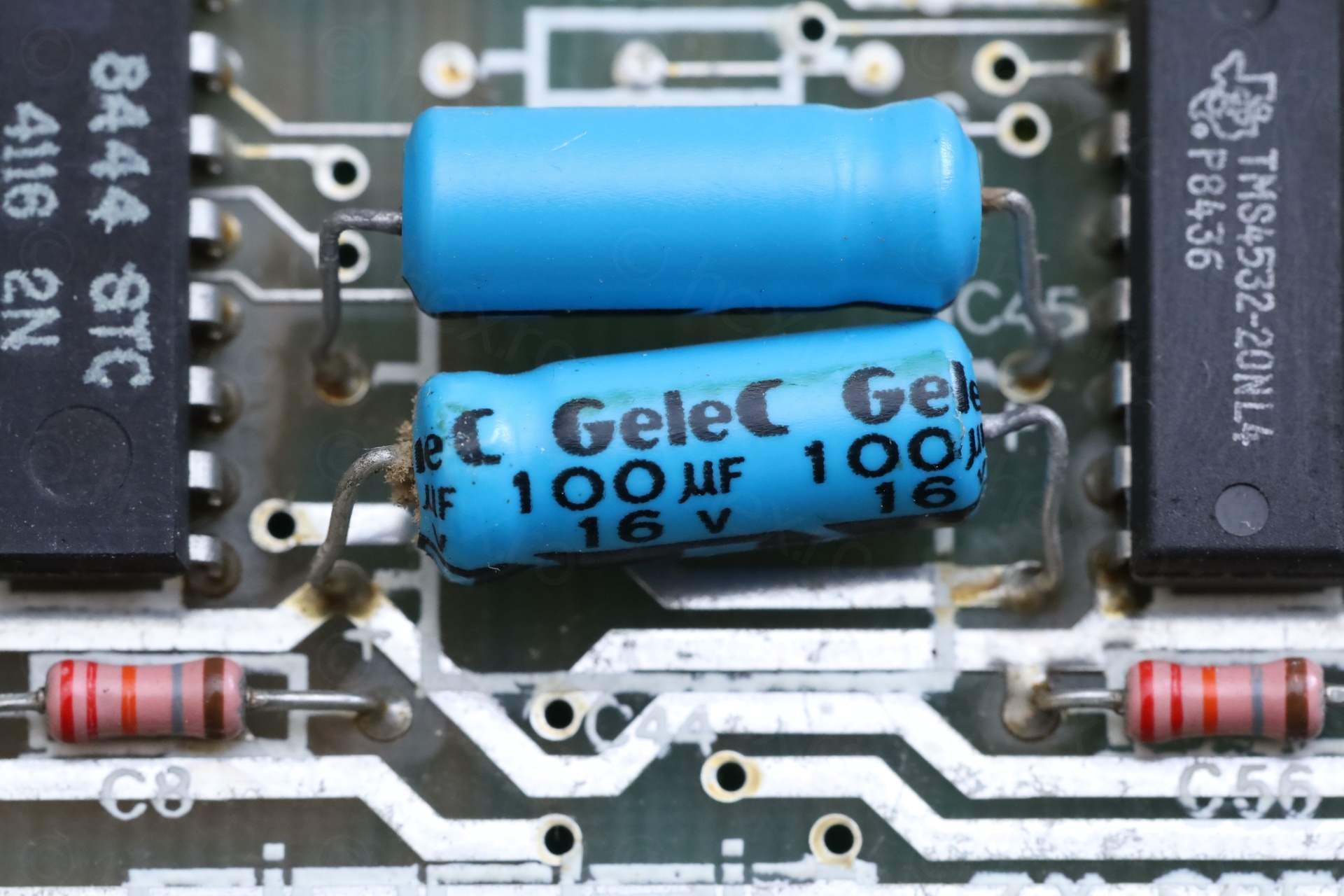
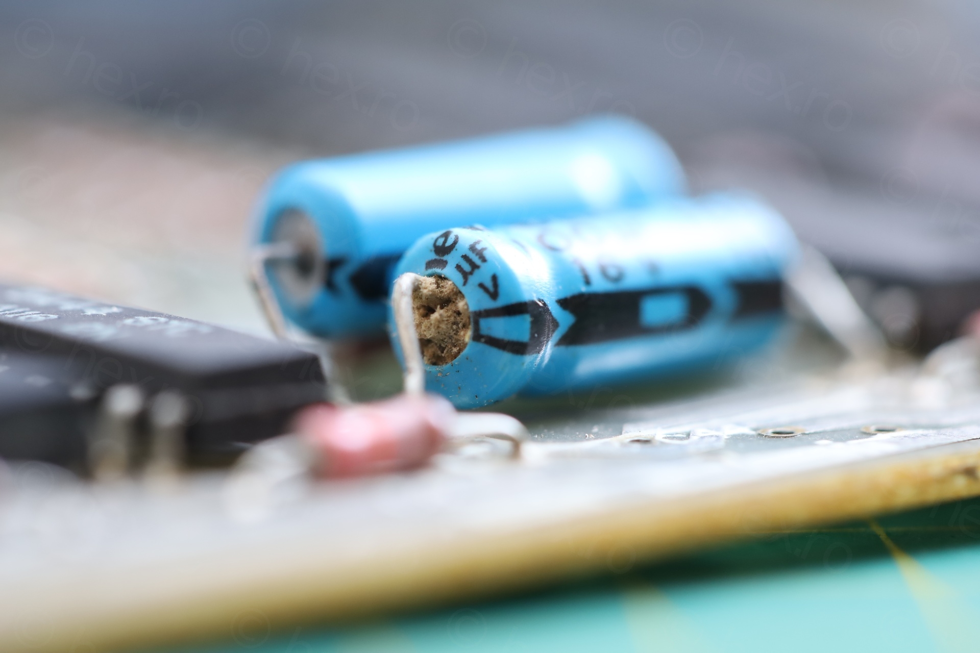
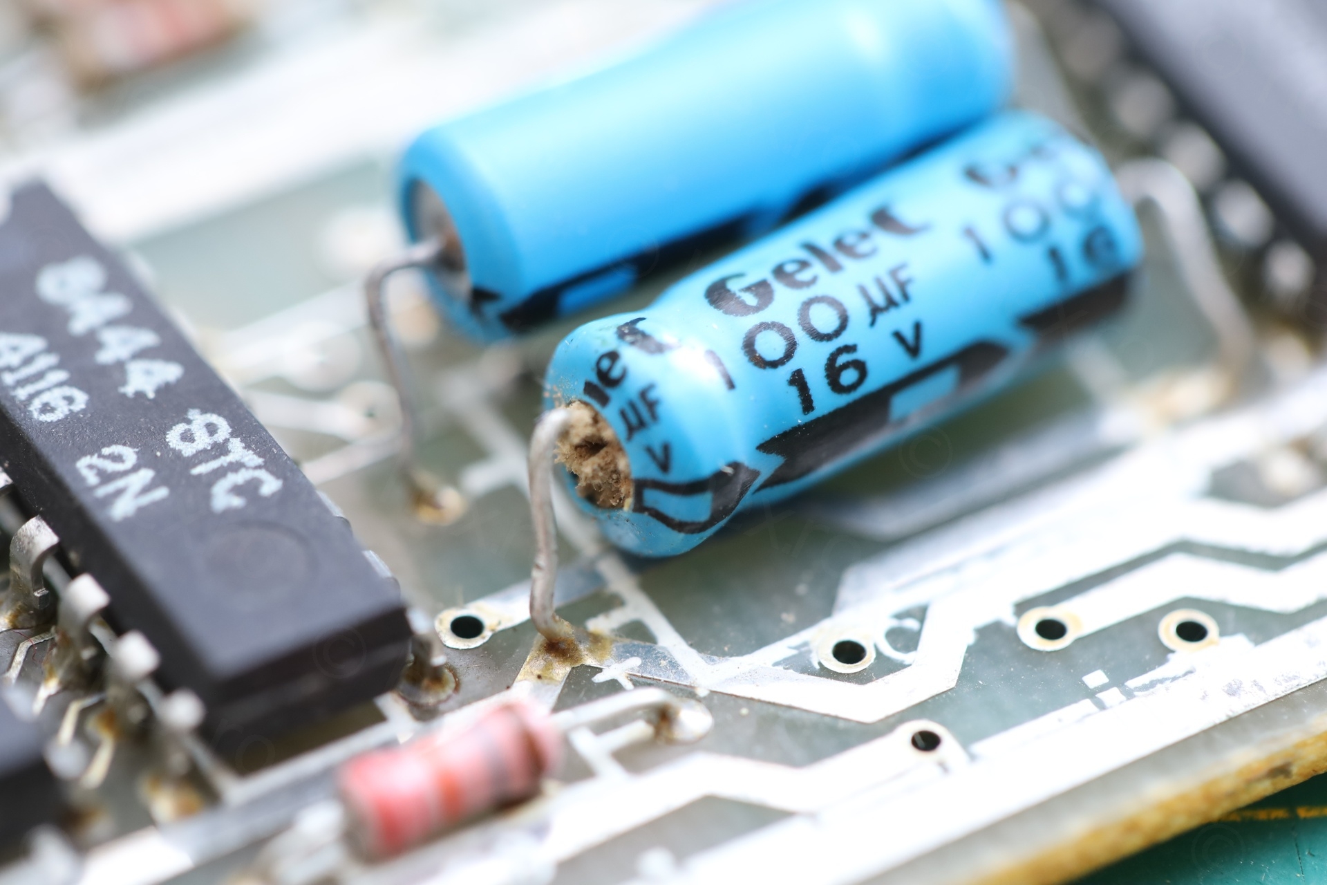
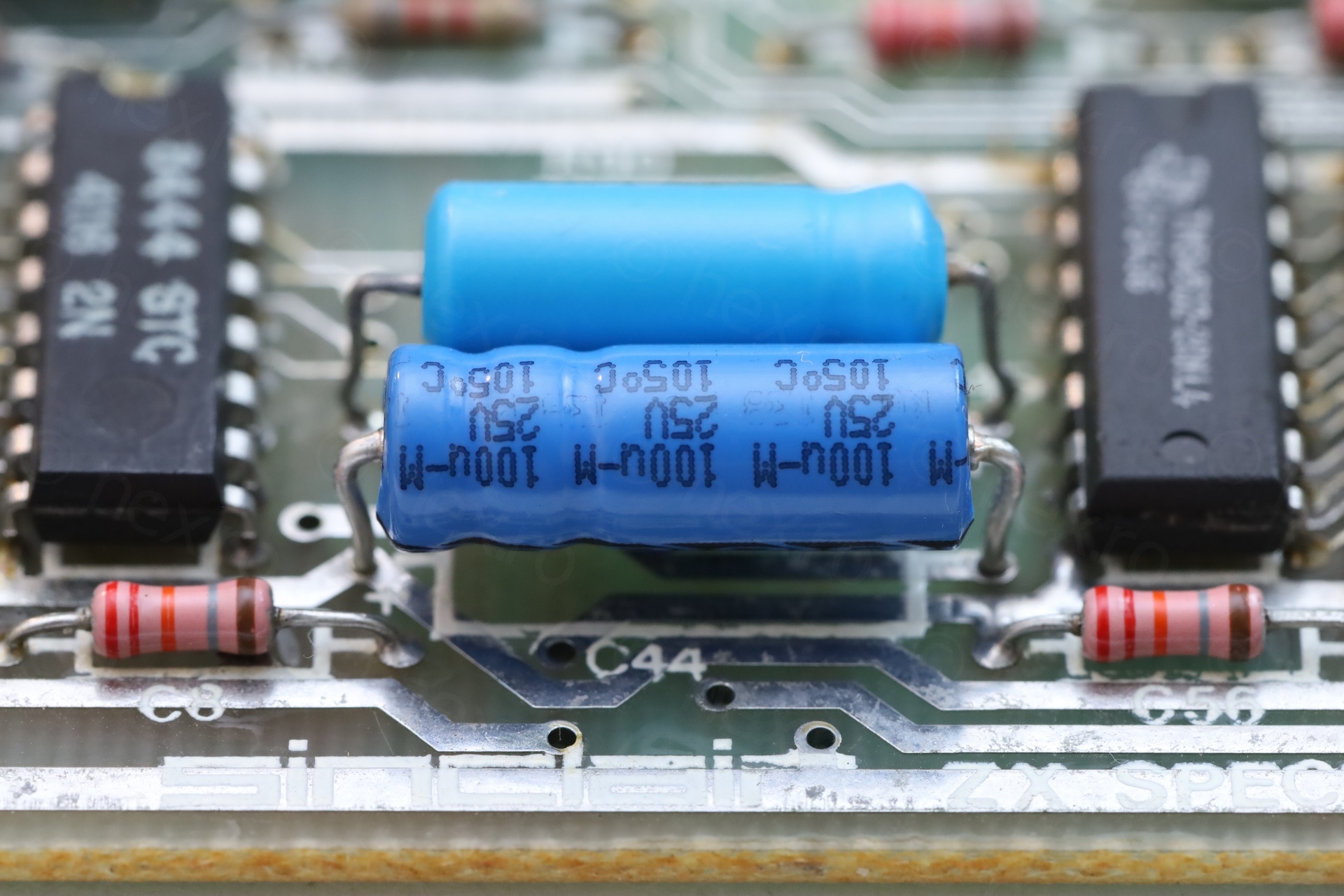
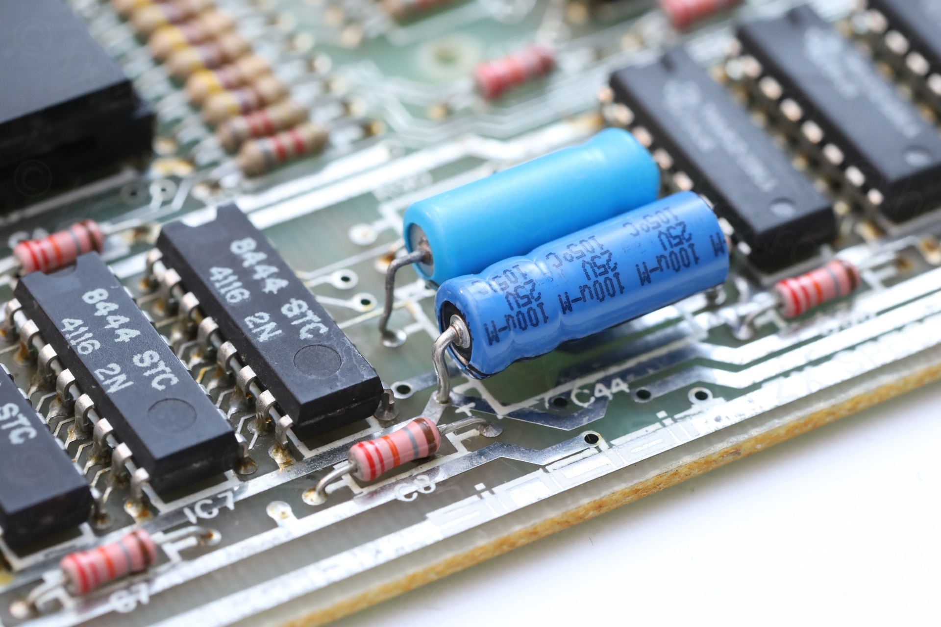
C44 is fluffy
C44 looked weird, a mix between being dangerous and a fluffy teddy bear that begins to show its filling.
The repair of this board took few iterations building up to fix. First iteration was fixing the obvious: reattaching the RF modulator and swapping C44 and TR4.
I did take some measurements beforehand – just to have something to compare to later on:
- 5V Line ✓
- +12V Line – reads as 0.75V
- -5V Line – reads as 0.45V
… and, at 10V, it draws 0.770mA.
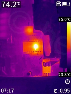
ROM gets hot very quickly, it reaches 75C in less than a minute:
Fixes
Iteration 1
RF Modulator reattached
I re-soldered the connections properly and “deleted” this mod attempt.
C44
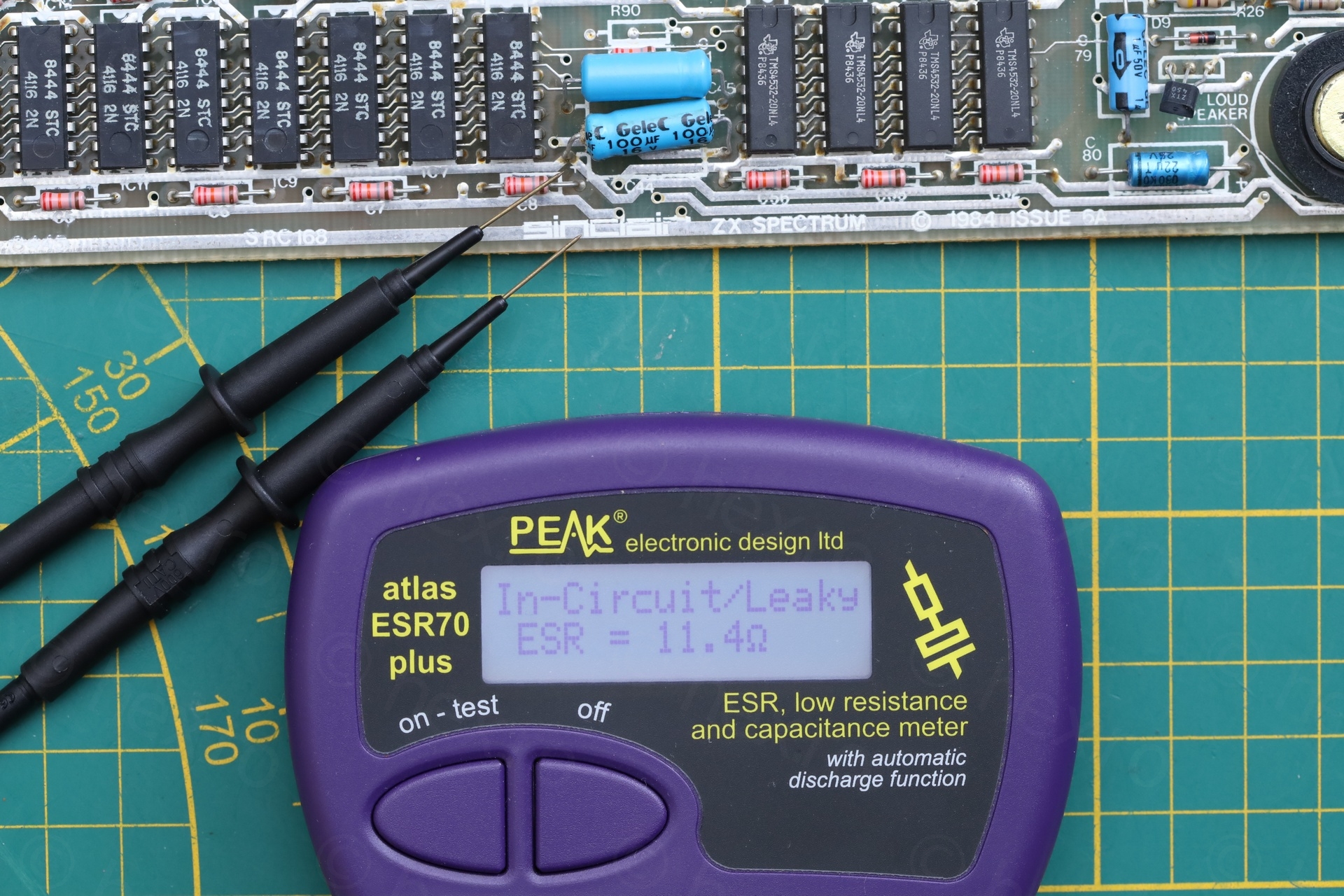
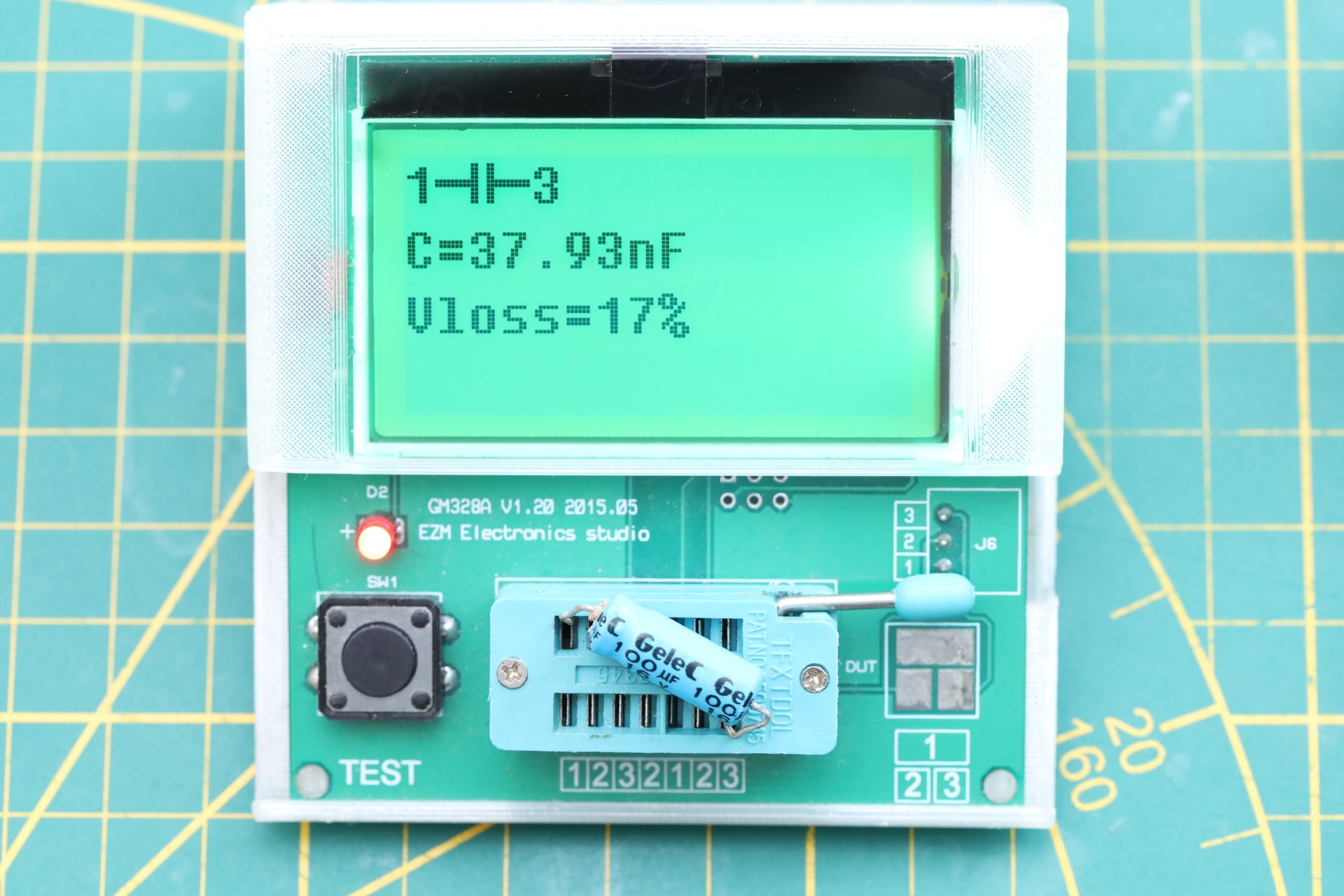
I measured it both in circuit and after removing it, it was obviously bad. I’m not keen on swapping capacitors without a proper diagnosis, but this one was too obvious:
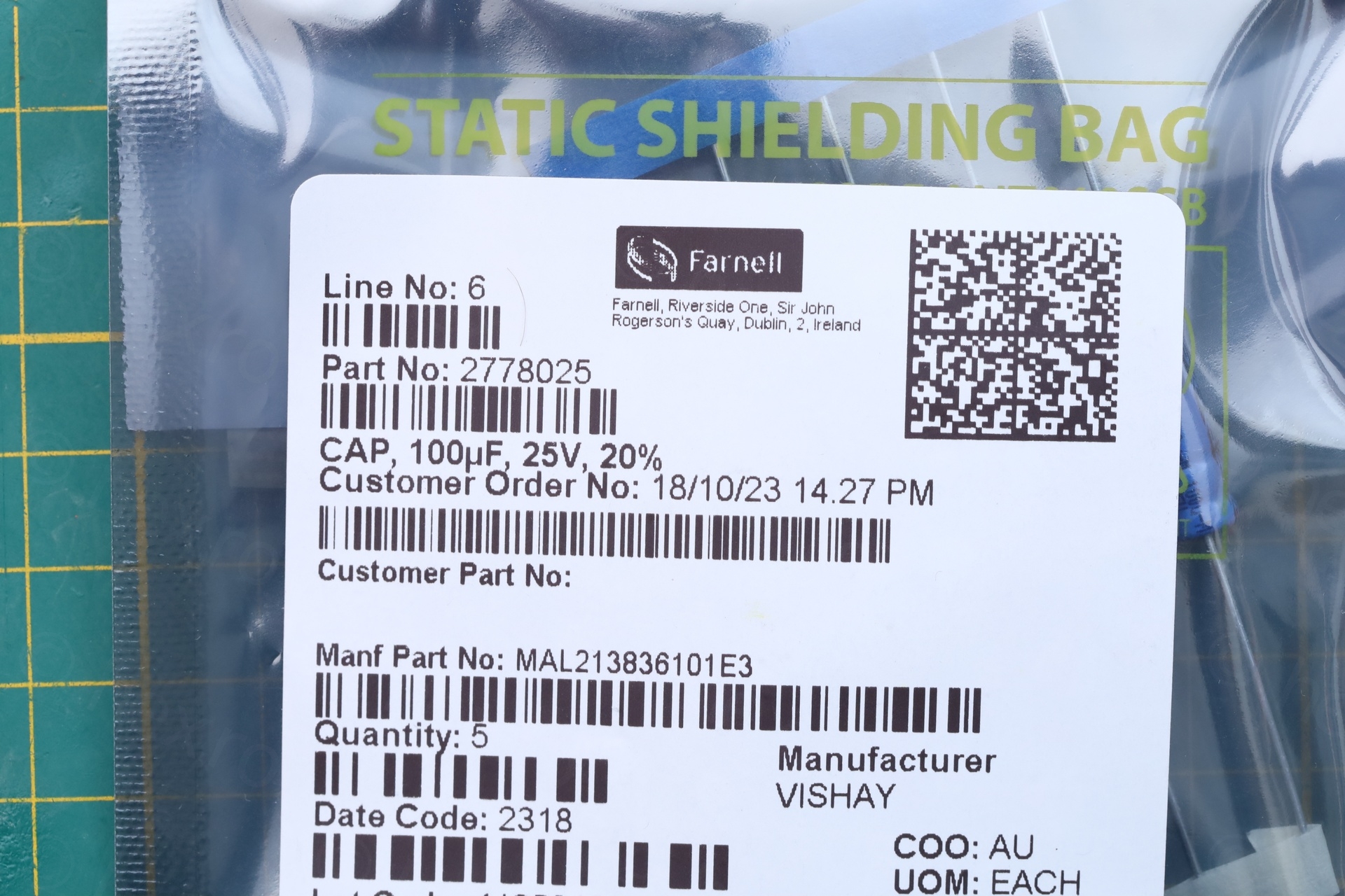
It got replaced by a Vishay 100µF @ 25V capacitor:
TR4
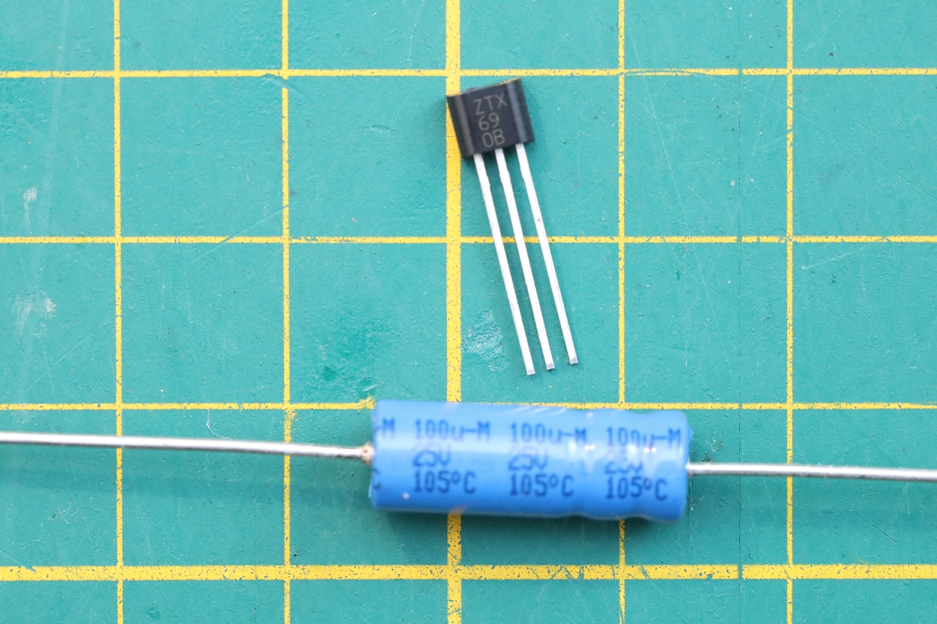
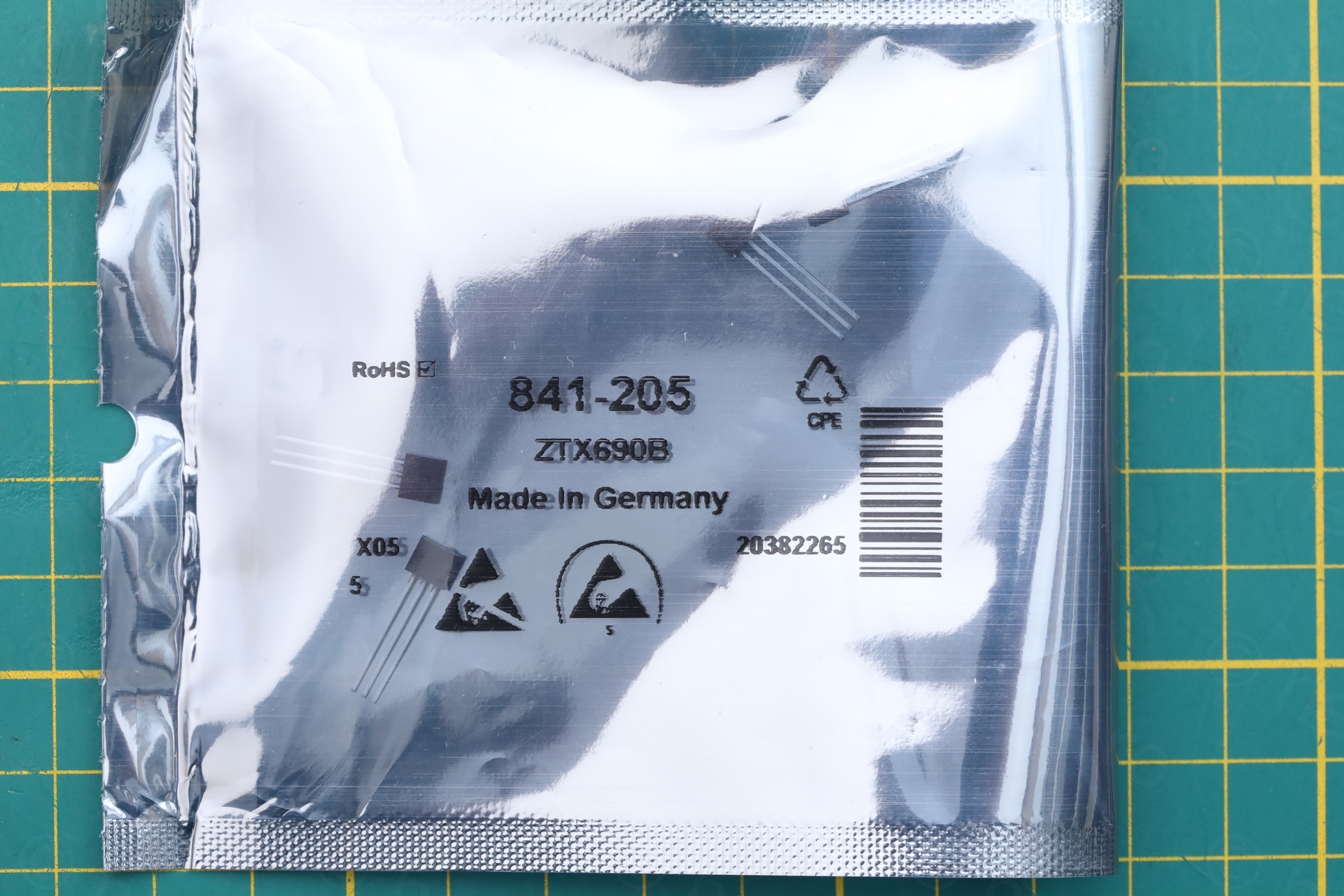
For TR4 (ZTX650 – NPN, VCE 45V / 2A / 1W / 175MHz) I will use this replacement: ZTX690B (NPN, VCE 45V / 2A / 1W / 150MHz):

Iteration 2
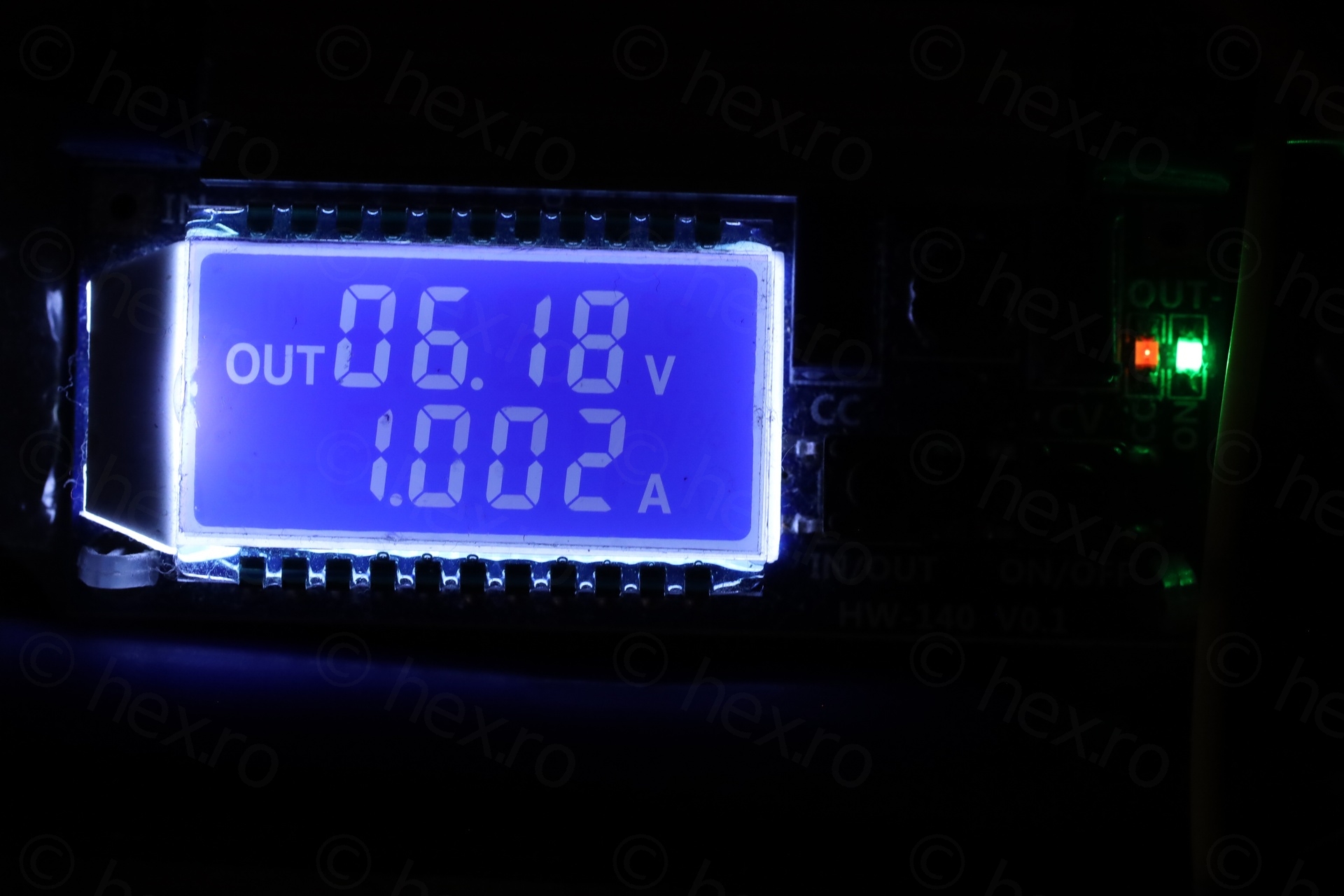
I was hoping for an easy fix and being anxious about the first power up after the swaps. But dissapointment. My desk bench power supply (sounds fancy, but is not) entered protection mode (lowering its output voltage to 6V to keep current limited to 1A):
Measuring voltages now would be useless plus running it like this is dangerous to the DC-DC circuit parts which will still try to make 12V happen.
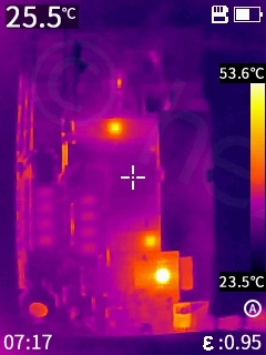
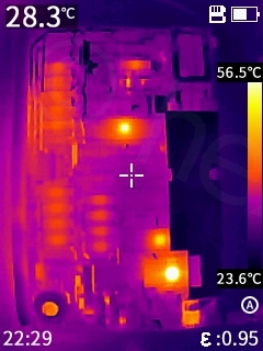
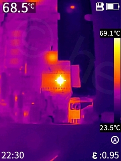
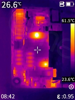
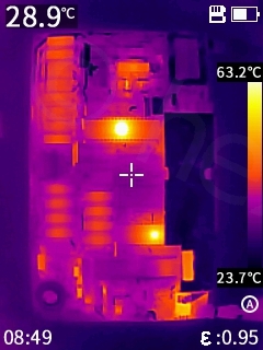
I quickly snapped some Infrared photos – in the hope to find clues for the next step.
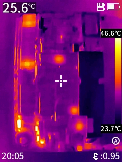
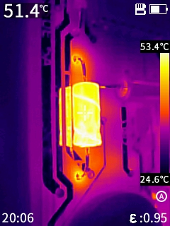
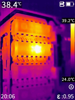
An interesting observation was that the ROM was not getting hot anymore! But, now C80 was getting hot (I assume due to increased frequency of the DC-DC converter trying to make 12V out of 6V at coil input). 3 lower RAM chips were also getting hot.
For good measure, I checked TR5 and due to some weird readings, I decided to check the LM7805 -> it measured 31.6Ω between OUT and GND. On a working Issue 3B board, it measures around 1k1 thus 31.6Ω is way too low.
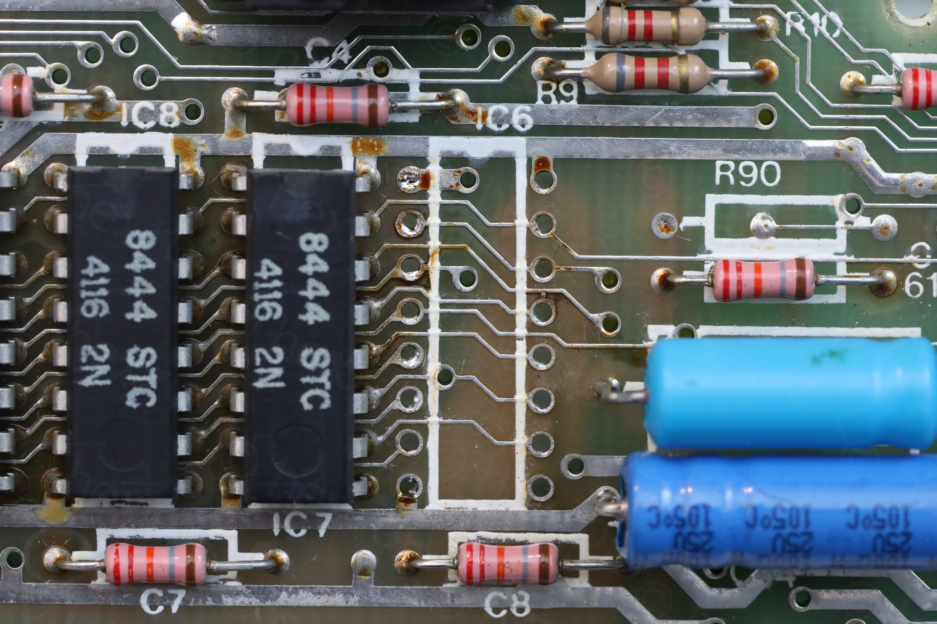
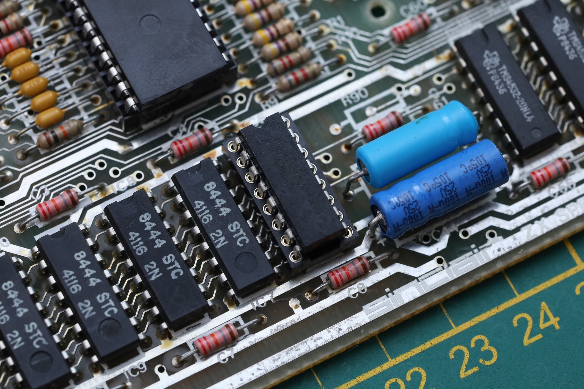
At this point I decided to remove the 3 lower RAM ICs, install sockets and good replacements. I could not tell if the lower RAM ICs are bad, or maybe a short in the ROM may cause them to act up ? I have no clue if this is possible, but ROM was initially getting very hot, when the 5V line was there.
Removing IC6
I proceeded to first remove IC6 and see how the Spectrum reacts.
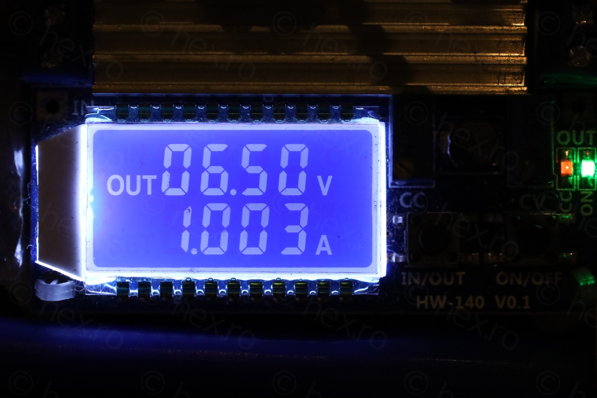
The results were encouraging, the power supply voltage climbed from 6.18V to 6.5V while keeping the current limited to 1A – as you can see below.
I was curious to test the IC in a separate memory tester. I found that the IC is so shorted, it even messes up the voltages on the tester. Have a look, once I clamp it down, flashing lights everywhere:
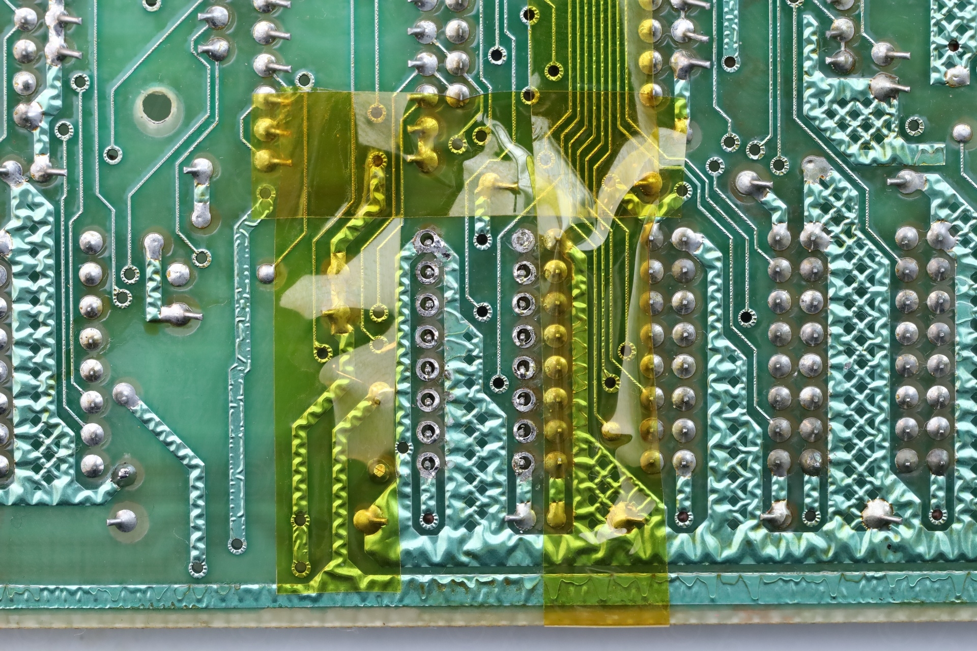
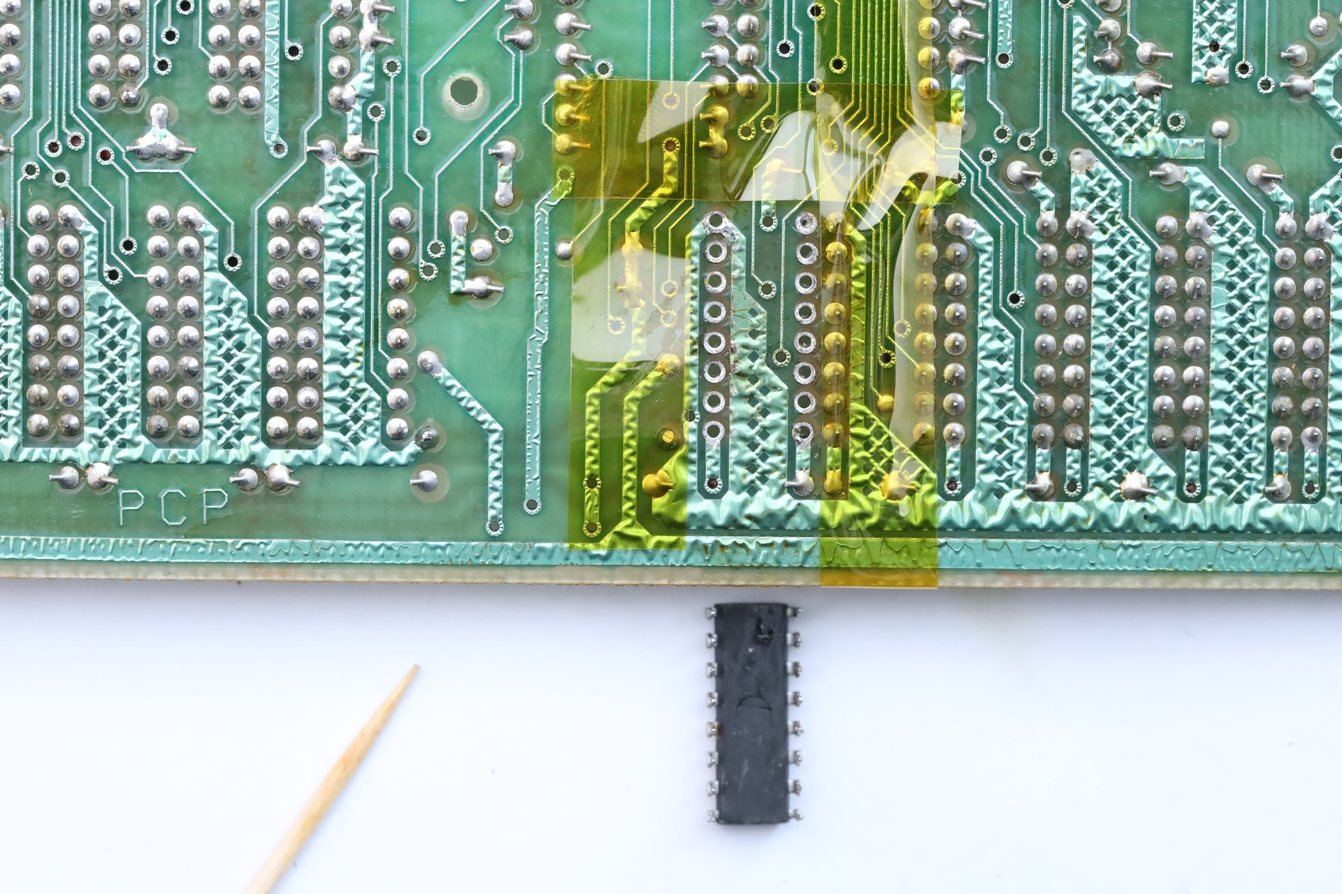
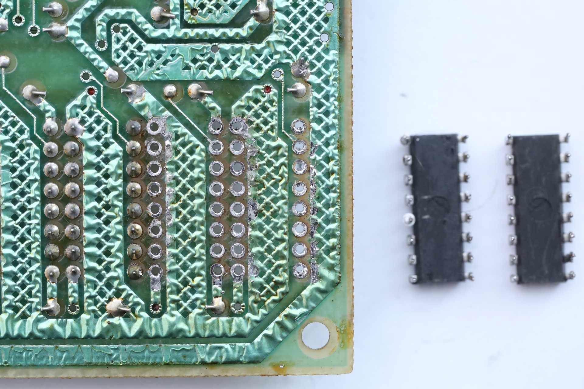
Removing IC12 and IC13
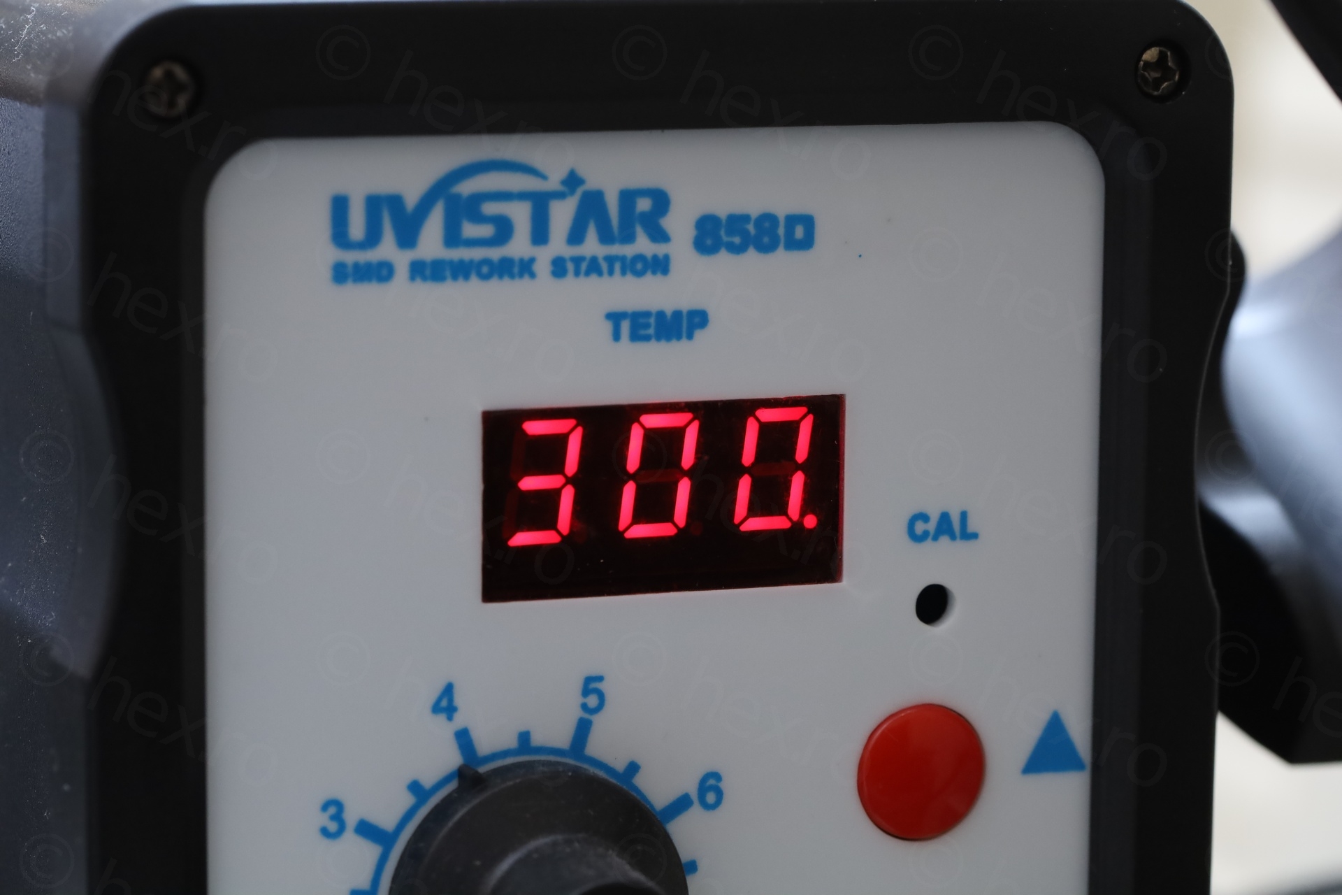
Same procedure: first, remove as much solder as possible with the solder sucker (I use a PN-998 Electric Vacuum double pump); then, using the hot air gun at 300C and some patience, try to gently press on the pins of the ICs until they start to slide and the IC now distanced itself from the board; continue with heat gun but, reach underneath the board and gently pull down on the IC using a toothpick.
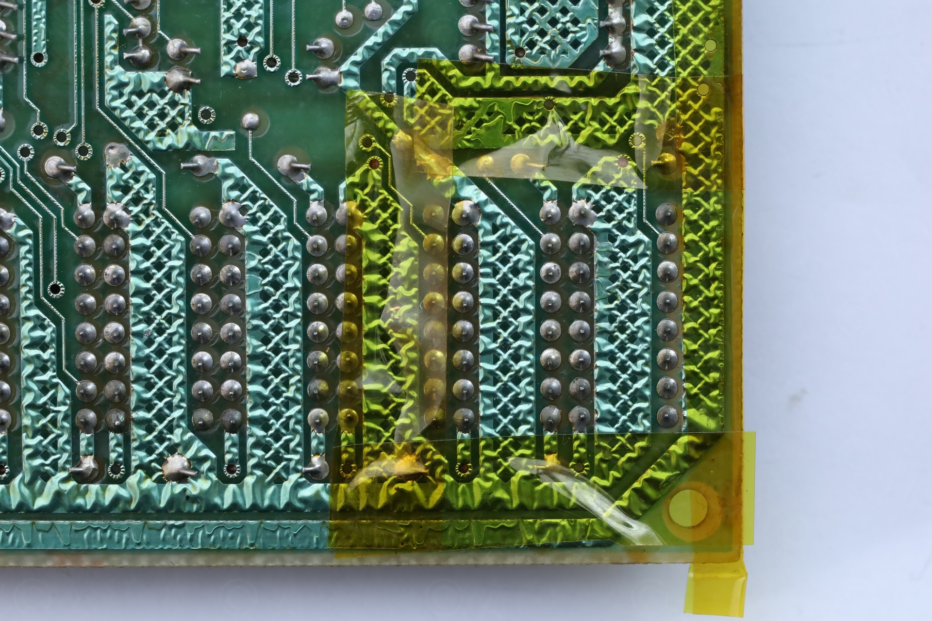
I have made a bit of a mess unfortunately. I was always using the 1.5mm tip of the solder sucker. But it is too wide – I touched the solder (and melted the solder mask) of the nearby connections 🙁 I never used the solder sucker so much and felt confident with 1.5mm. But, uf, lesson learned now. I switched to the 1mm wide tip after this.
But what about the computer ?
Without the 3 ICs, desk bench power supply was finally able to provide the 10V and current draw was just shy under 1A. But, the ROM was again getting hot! Pffff. It just never ends.
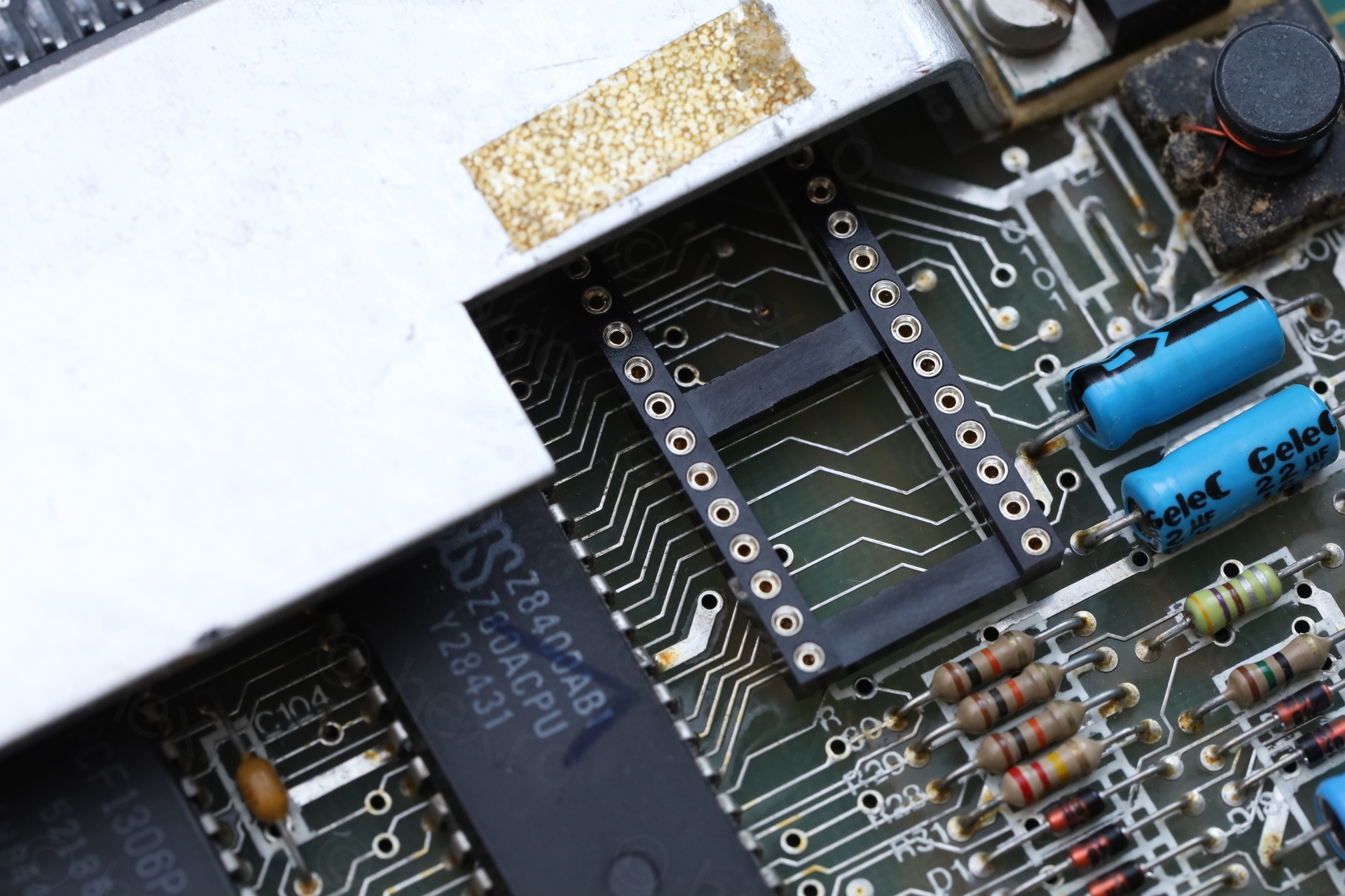
Removing the ROM
It was time to also remove the ROM. Using the proper 1mm tip for the electric solder sucker, no more damage to the nearby solder mask:
Finally, the computer was now only drawing ~0.6A – which is much better:
It was now time to run it with an external diagnostic ROM cartridge. To confirm that at least the ULA and CPU are working. And they do! The RAM FAIL message is normal, I was running it without the three memory ICs. It is a confirmation that the others remaining are still good:
Completing the repair
Reflections
The essence of the Sinclair ZX Spectrum is the ULA and the ROM, without either of them, it feels less Spectrum to me … Shall I invest more time in the board, or just use it for spares later ? On one way, it was frustrating the ROM is bad. On the other way, I reached that far and not to finish it ?
The breakthrough came when I figured that I could fix the board and use it as a reference board for other Spectrums in the future. It is the first Issue 6a motherboard that I fixed so it would be nice to know it is complete.
I do own two spare original Sinclair Spectrum ROMs. By using a socket, I could later drop in an alternative ROM (I see two models, one from Retroleum and another seller but those are out of stock) which don’t require PCB modding.
Iteration 3
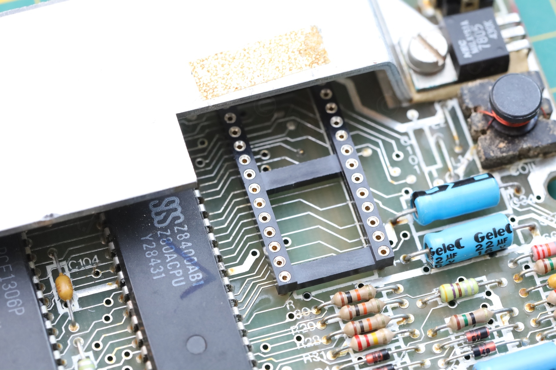
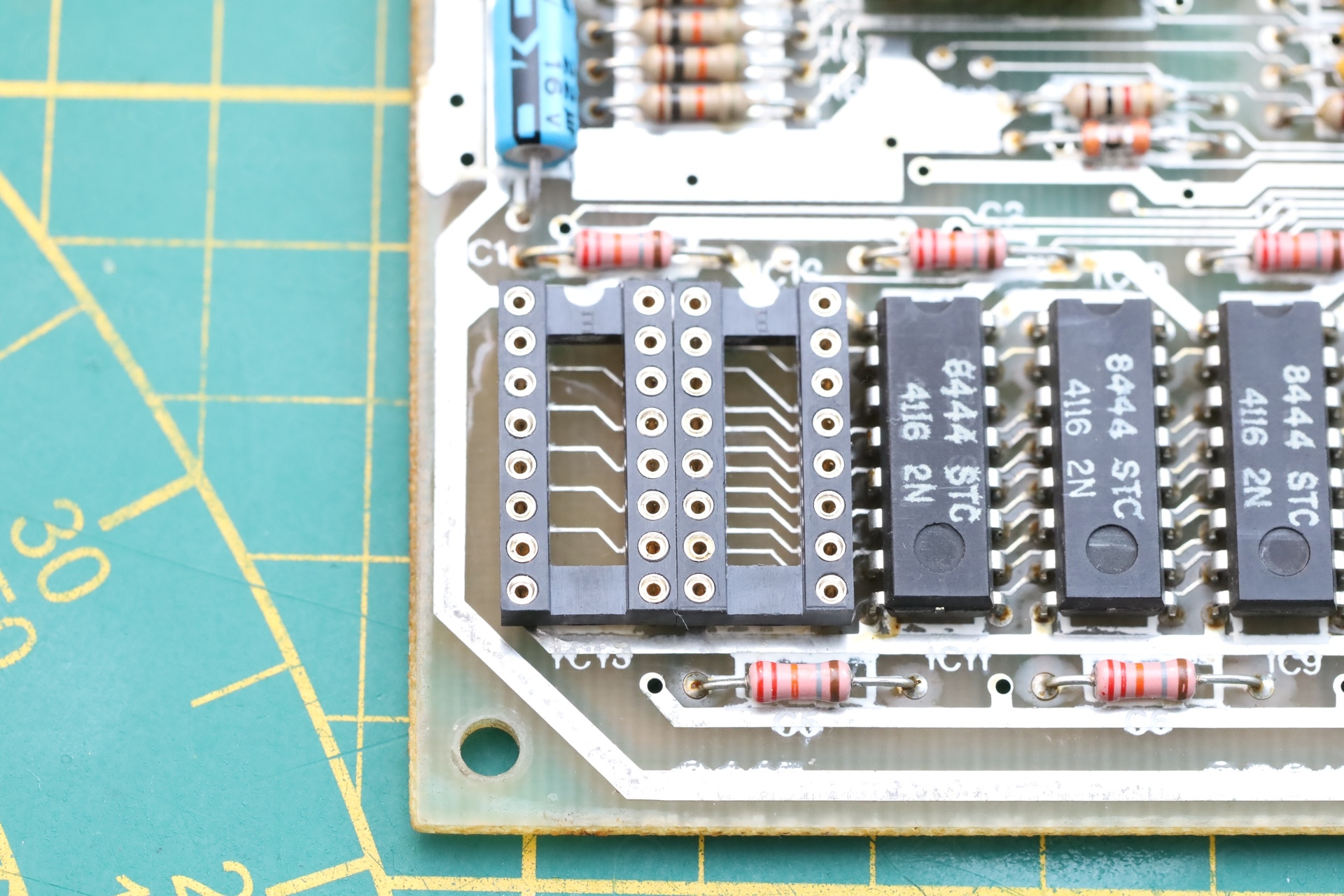
I started by soldering the 4 sockets, 3 for the bad memory ICs and 1 for the ROM:
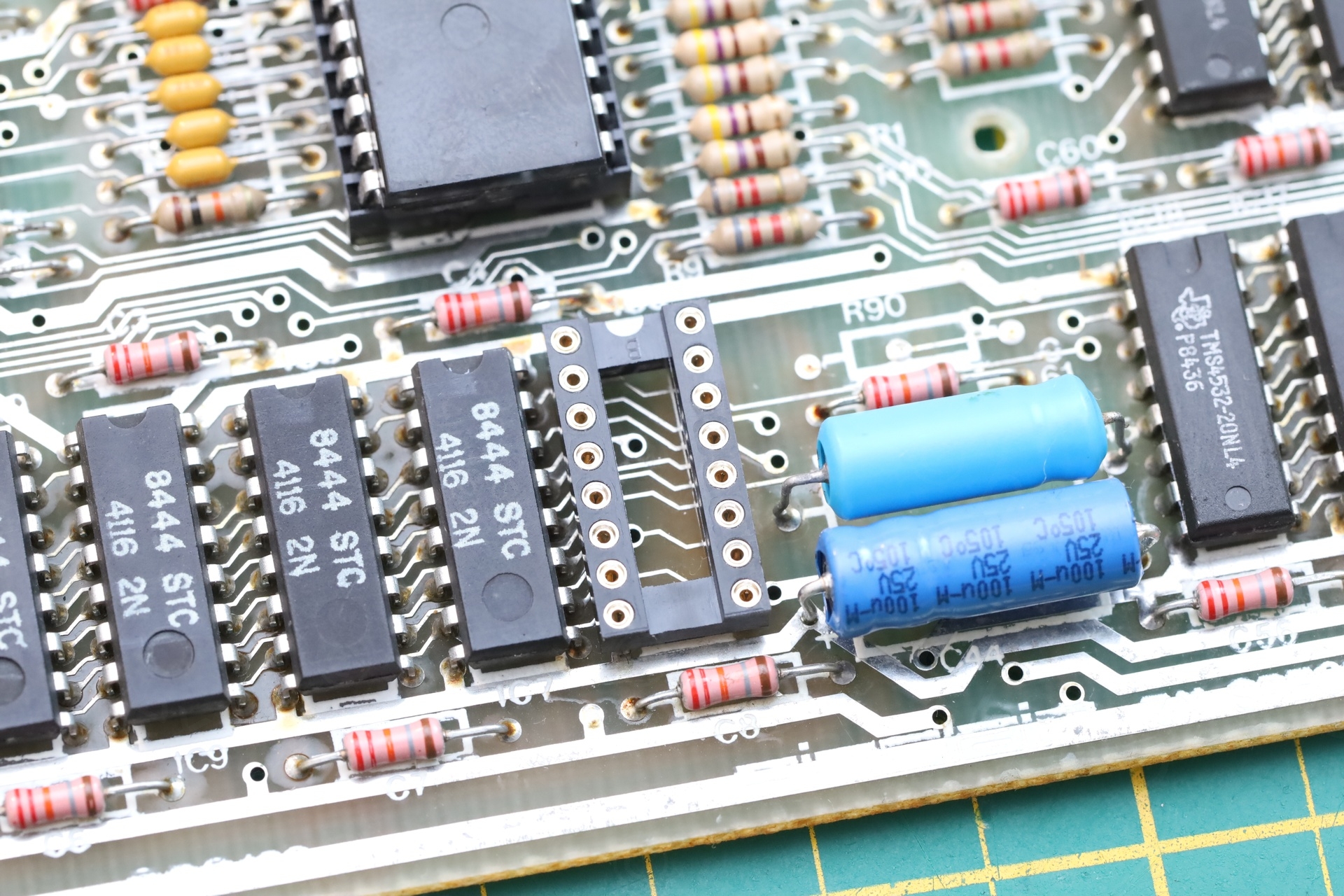
When taking the 3 hot memory ICs out, one of them was still testing good in the tester (while the other two were shorted, messing with the voltages of the testing board). But how would this IC get hot inside the Spectrum, but working in the tester ? Was there something on the board causing it get hot ? I decided to keep it and prepared it to be reinstalled by cleaned its pins of solder.
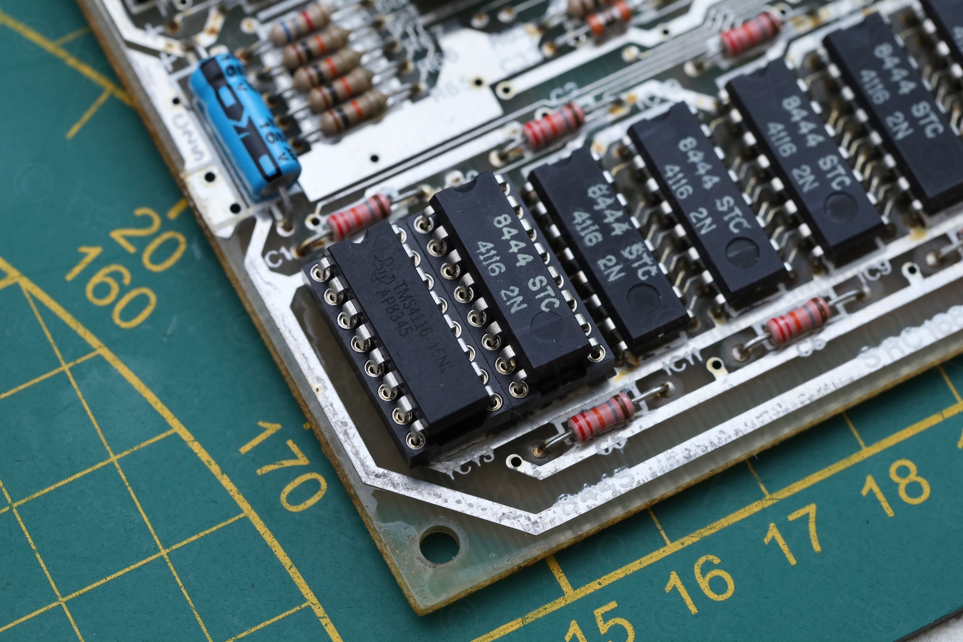
I also proceeded to install a socket for the ROM, and an original Spectrum ROM inside it:
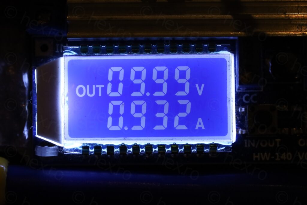
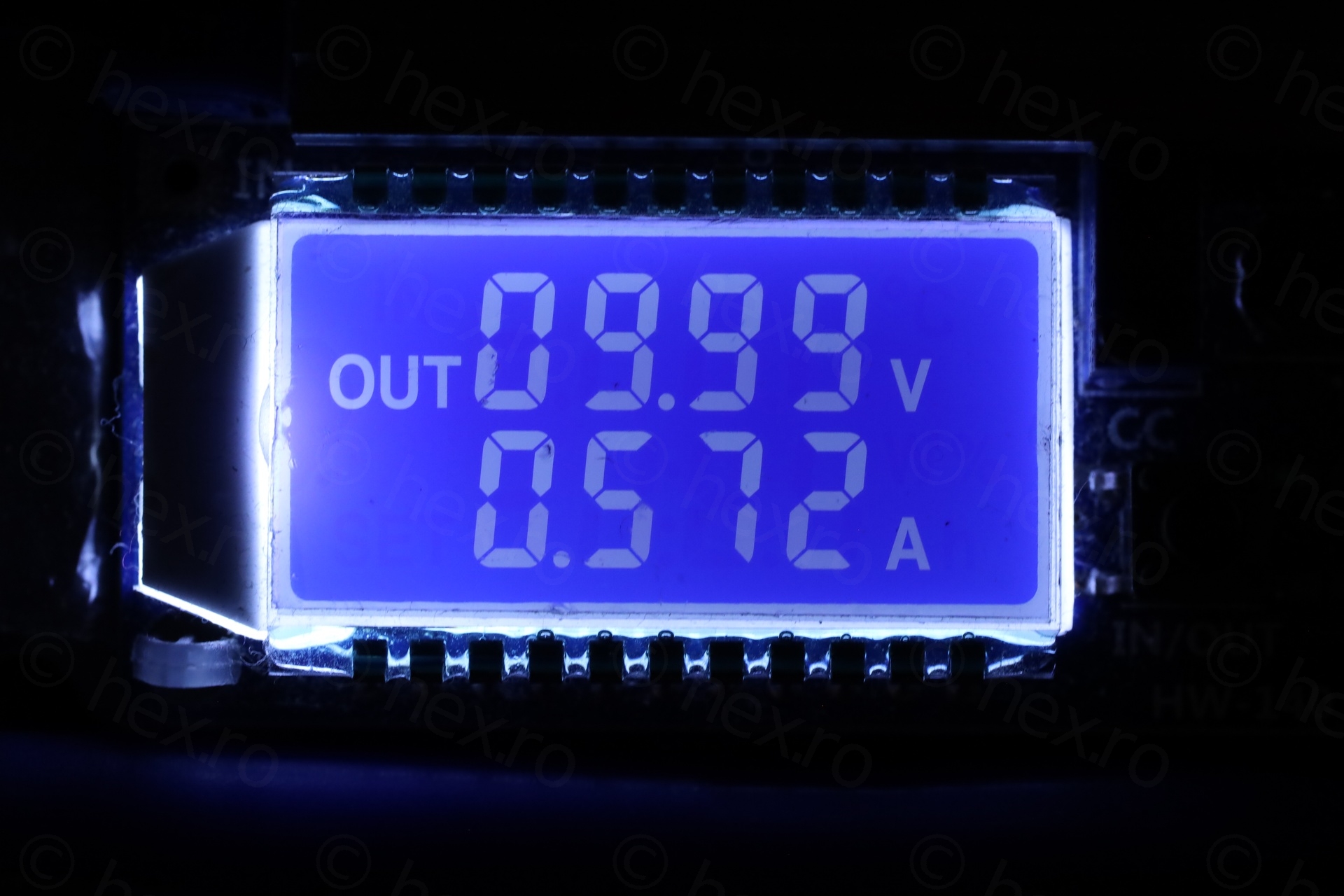
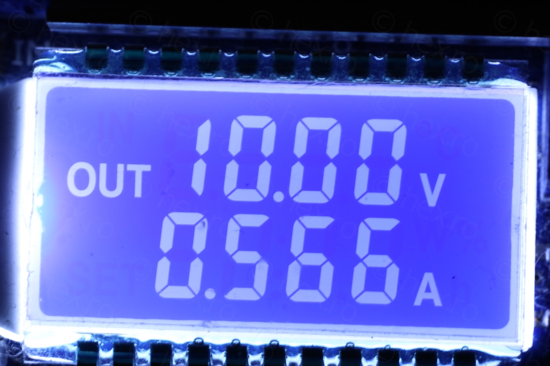
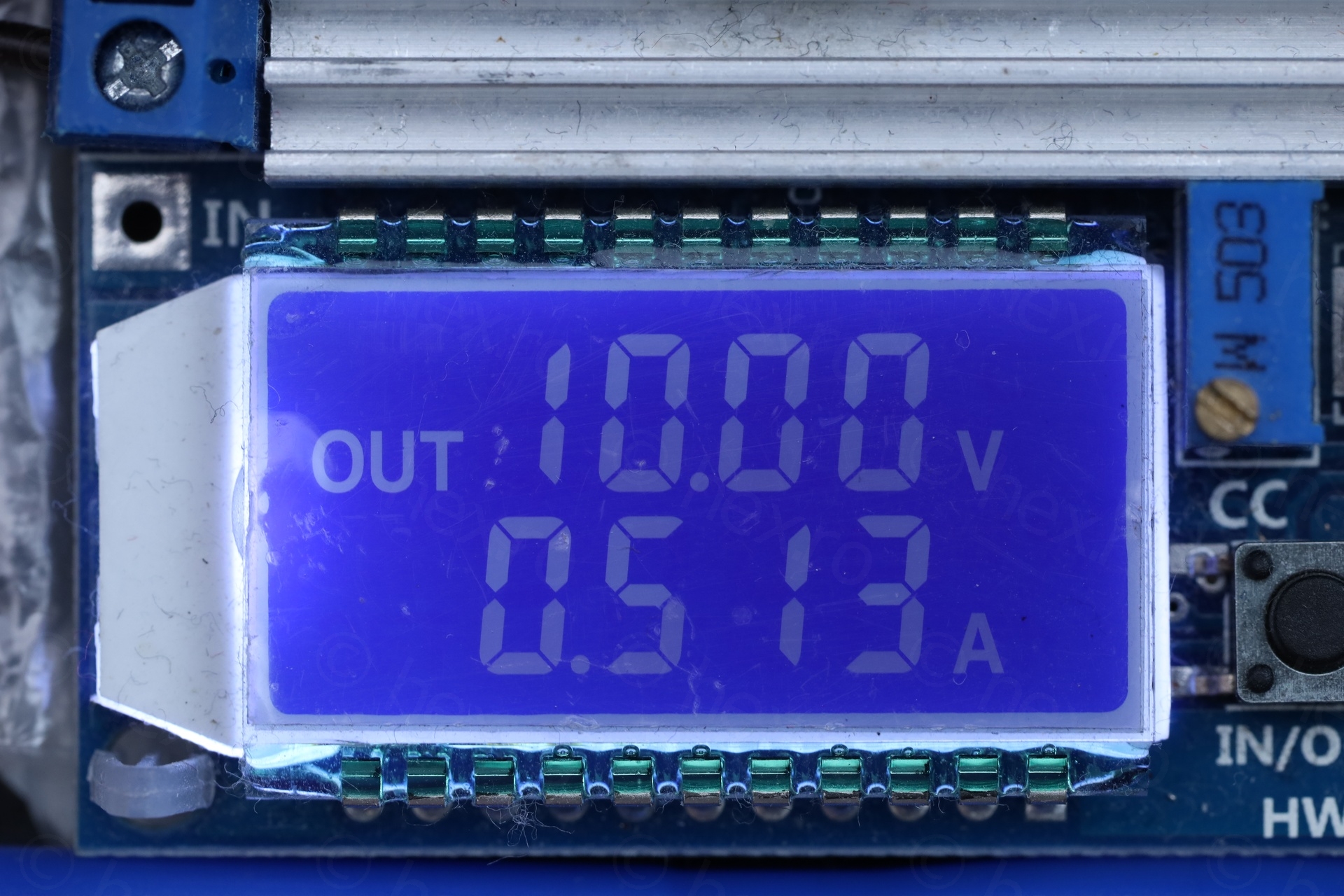
The motherboard is finally working, drawing 566mA at 10V:
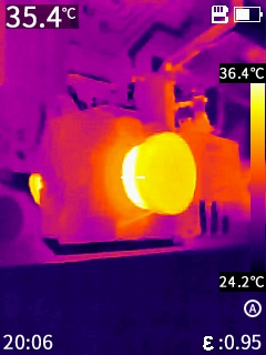
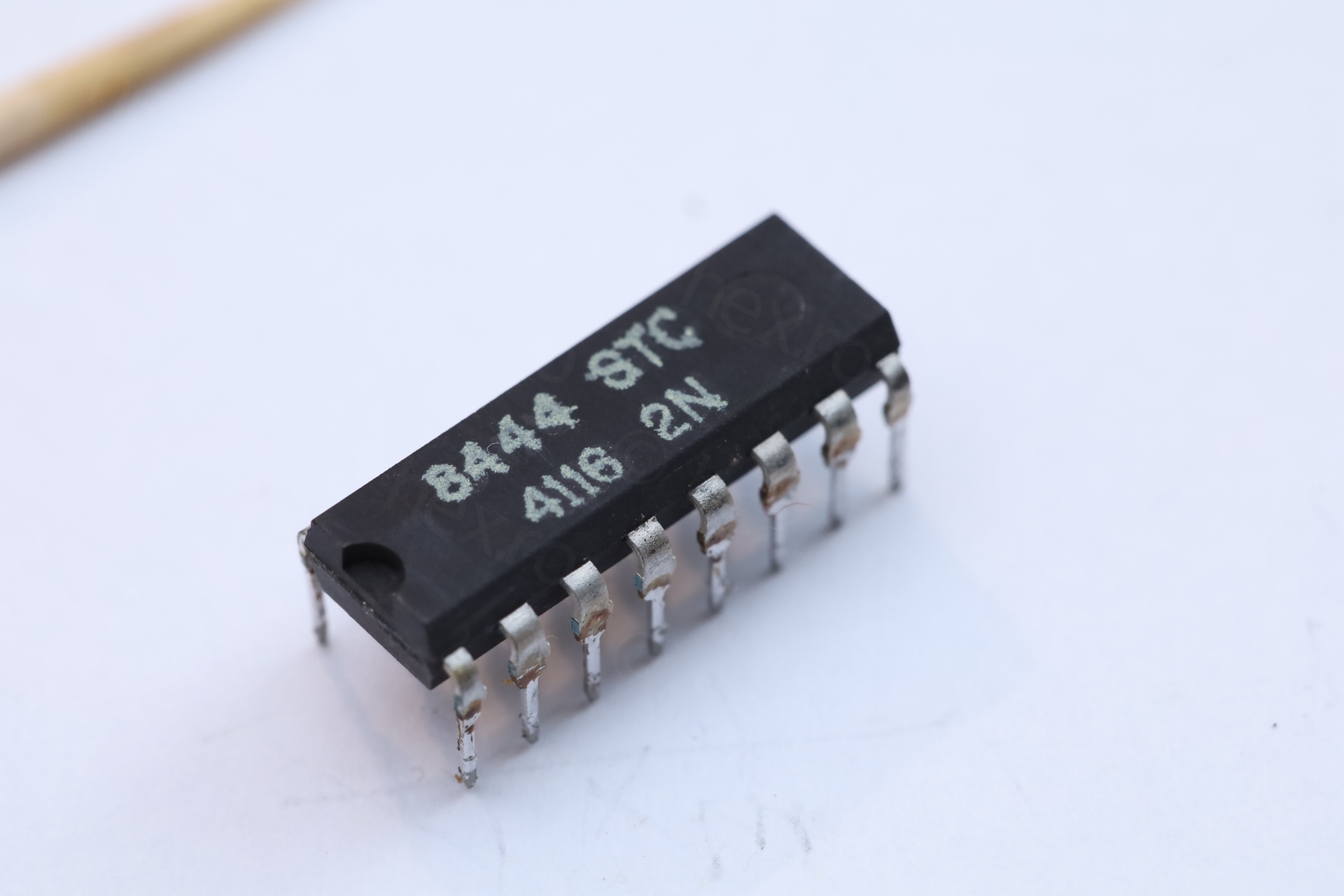
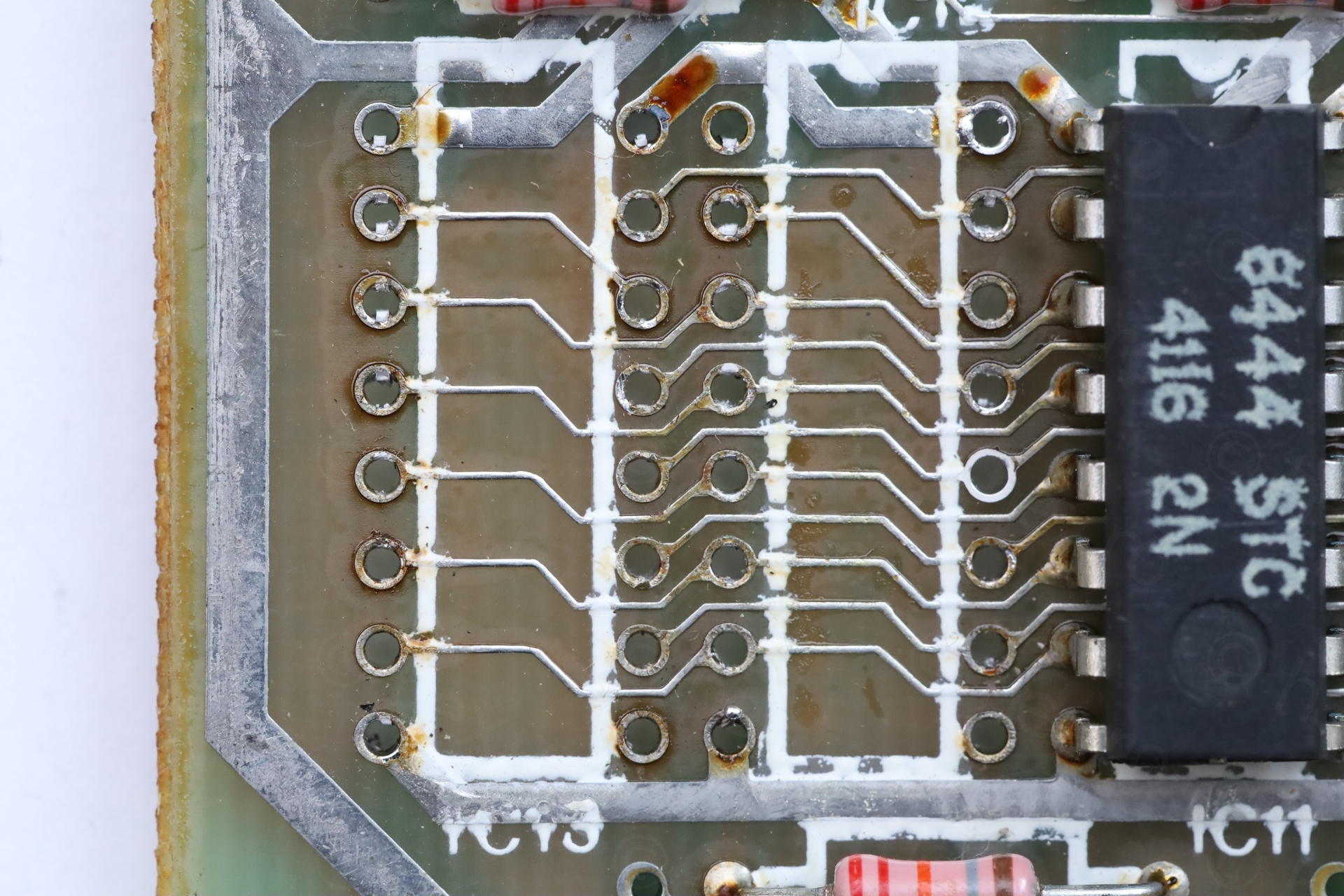
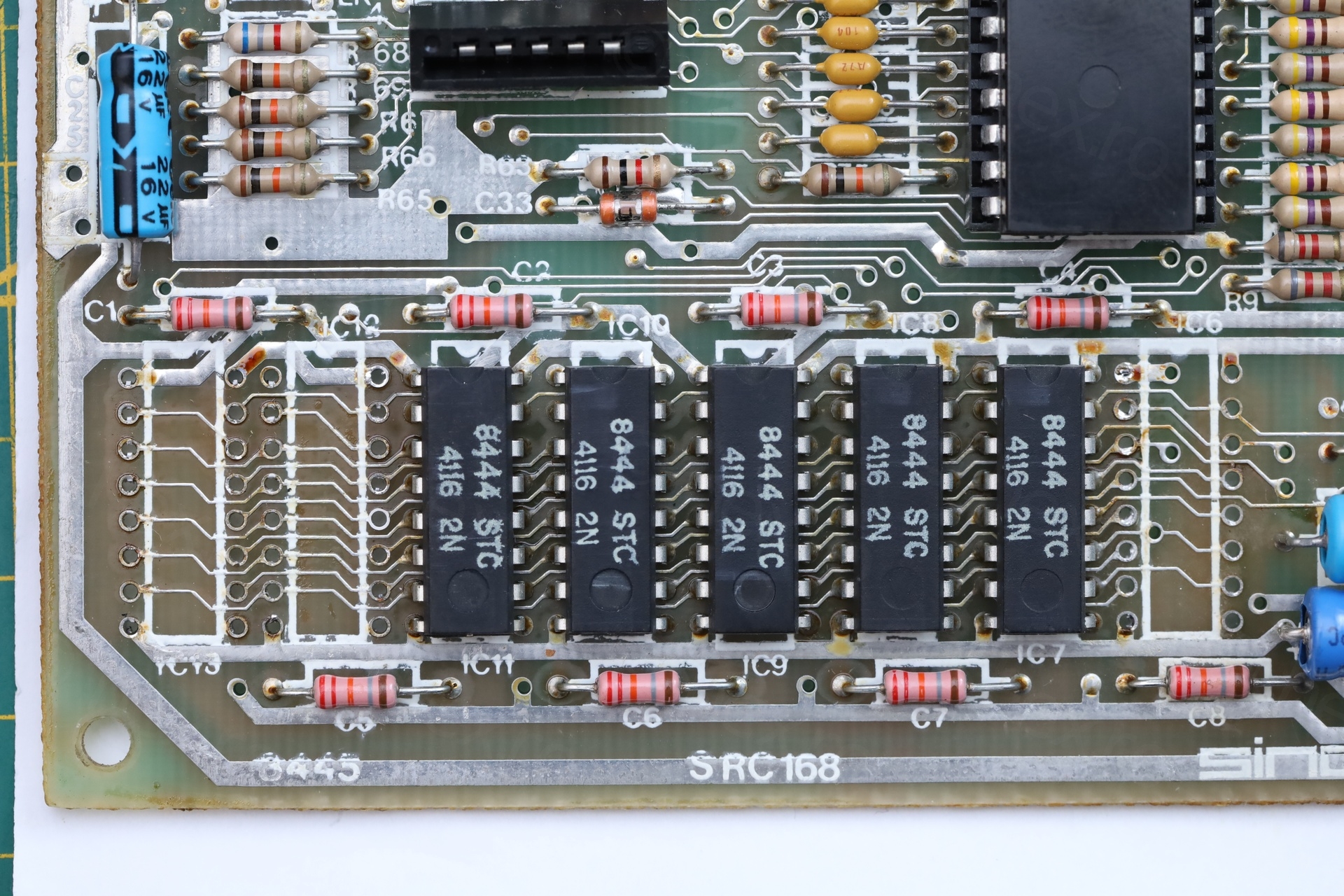
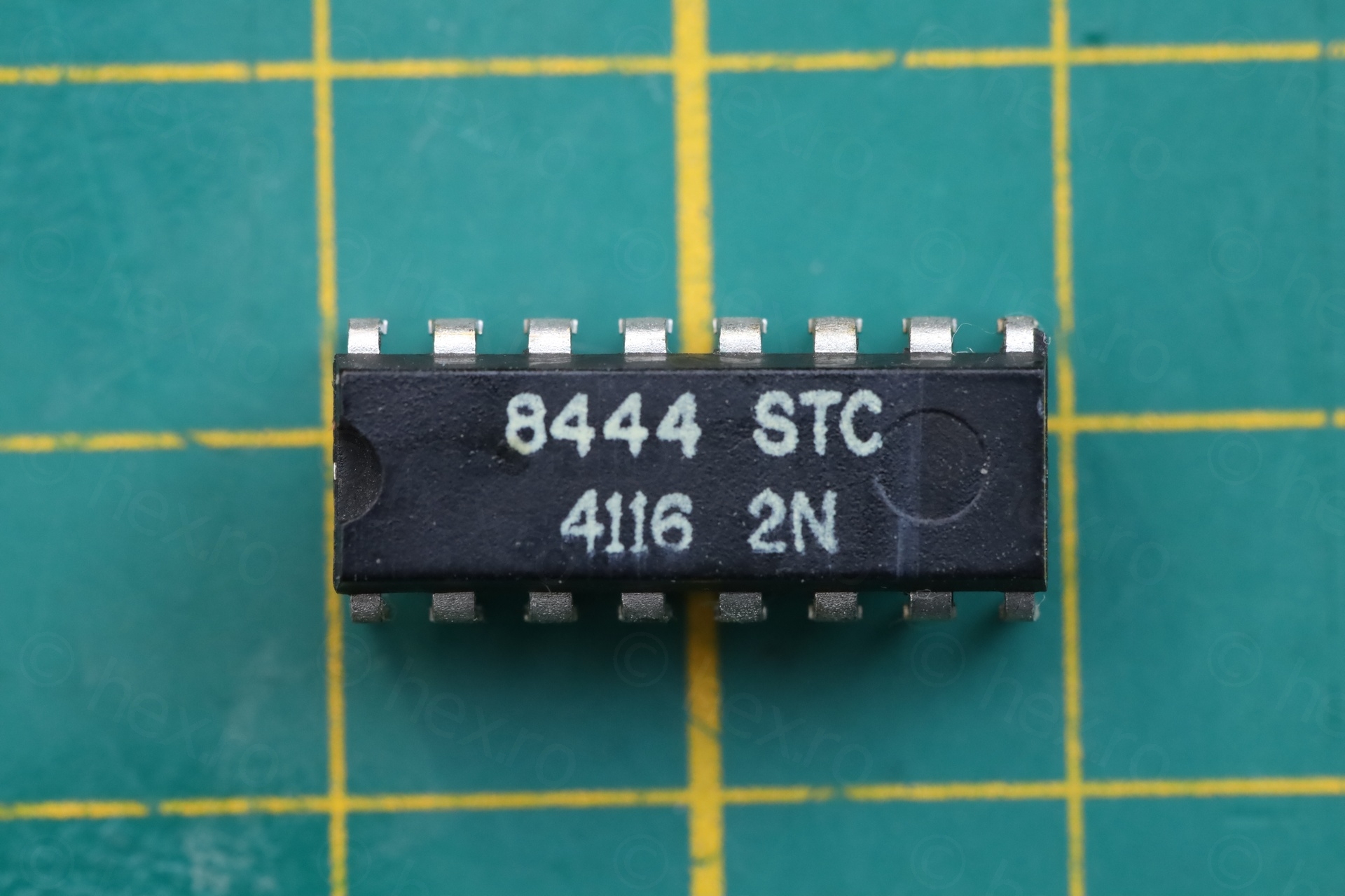
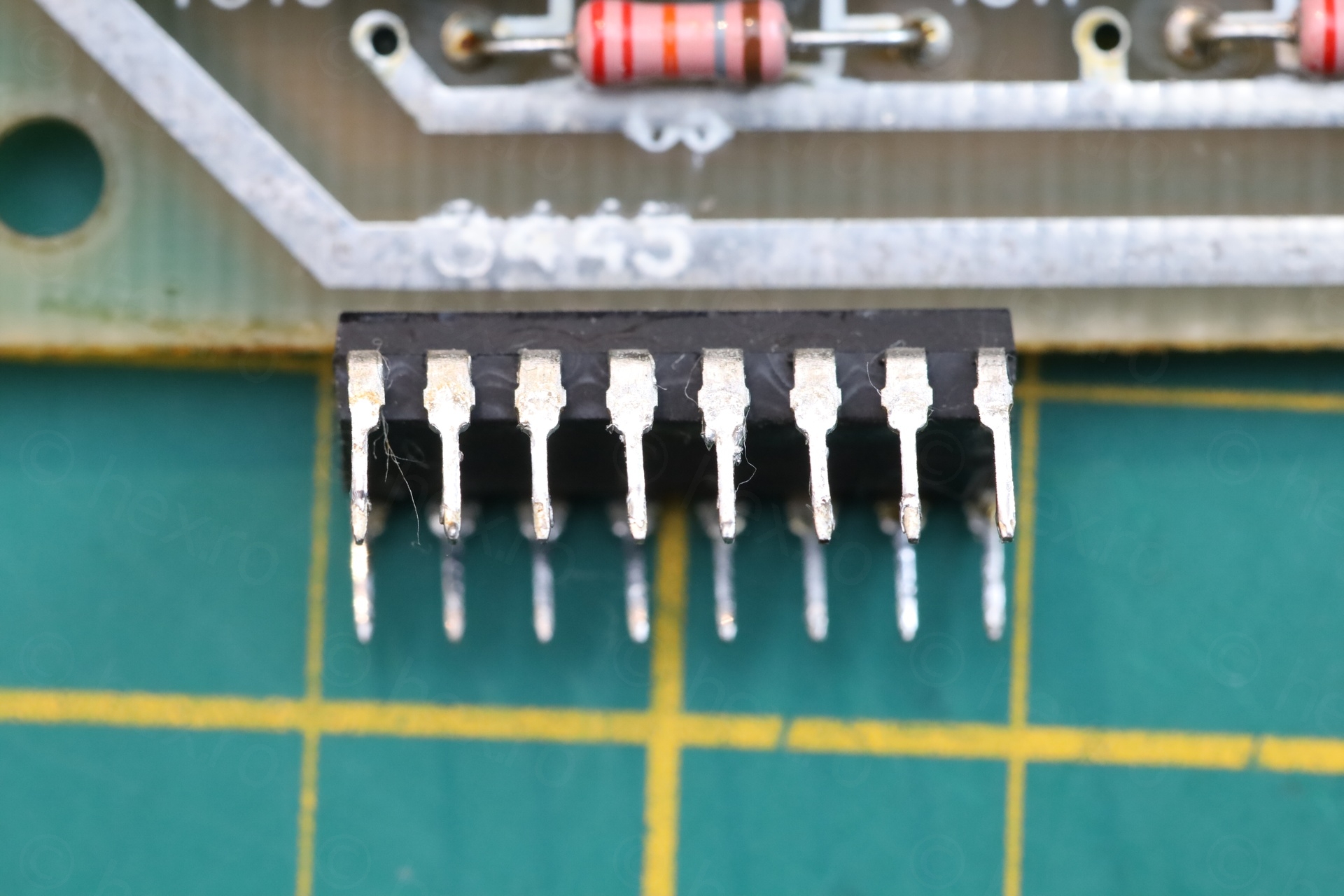
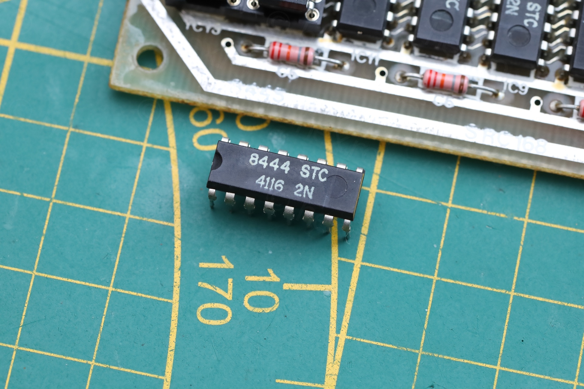
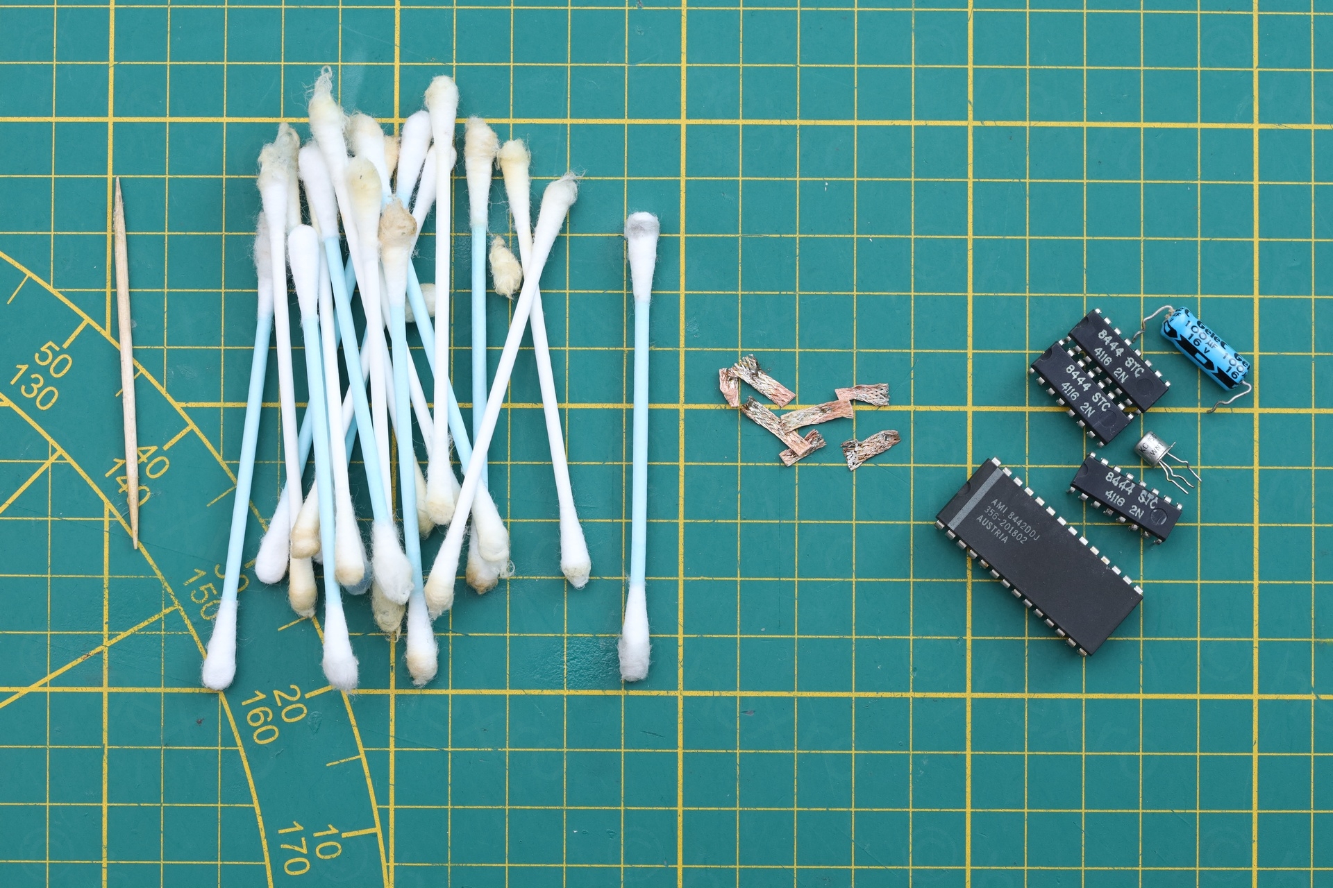
Out of curiosity, I figured, I should take one more infrared photo to document this repair. Hehee .. the board had one last trick up its sleeve – the original STC 4116 chip was still getting hot!
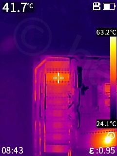
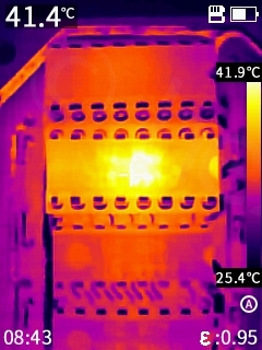
My mistake was to assume that if it works, then it must also be cold. Incorrect.
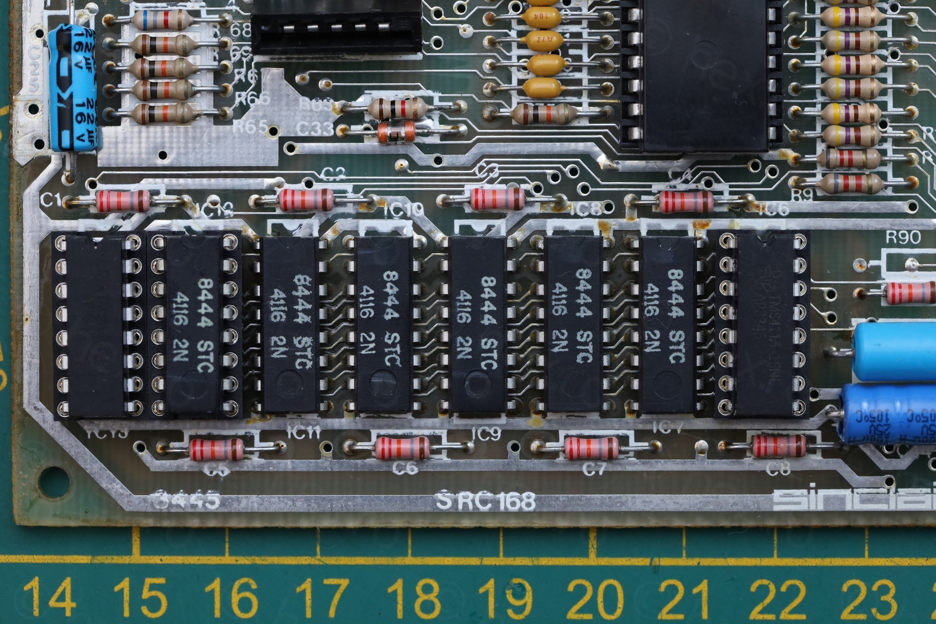
After swapping it, the board consumption dropped with 50mA. Now, all was fine:
I checked the LM7805 resistance between GND and OUT: 1082Ω.
Summary
This was a tedious repair, given the amount of de-soldering / soldering I had to do.
The board needed:
- TR4 Transistor
- C44 Capacitor
- 3 lower RAM memory ICs
- ROM
- RF Connector reattached
Few more photos with the completed repair:
It is pretty 🙂
Ivan
BC637 is a good replacement for TR4. You just need to cross the legs of a base and collector as it is B-C-E pinout. 1A 60V hFE 40-160