
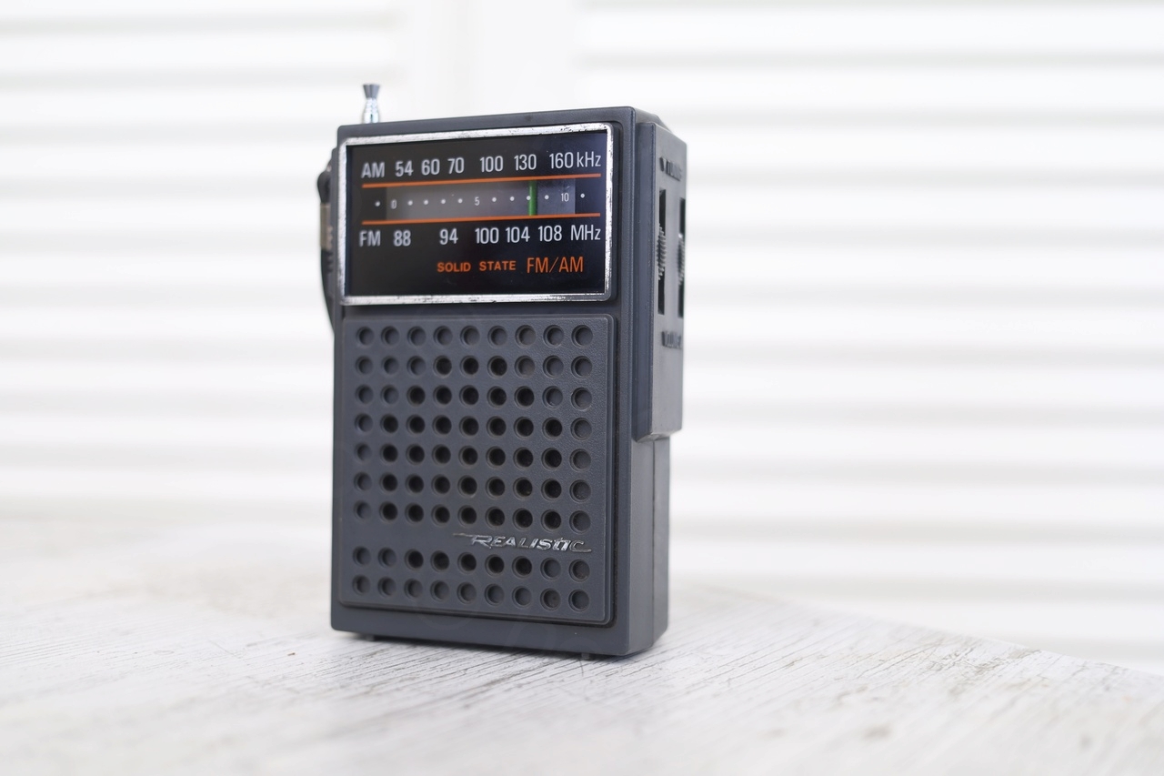
I got this radio from an old lady at a “garage sale”. She was very old but dressed well, thus, I think I chose to believe that this somehow extended to the radio, old and well maintained. I remember leaving very content of my acquisition, only to discover later how wrong I was. Pffff…
Overview
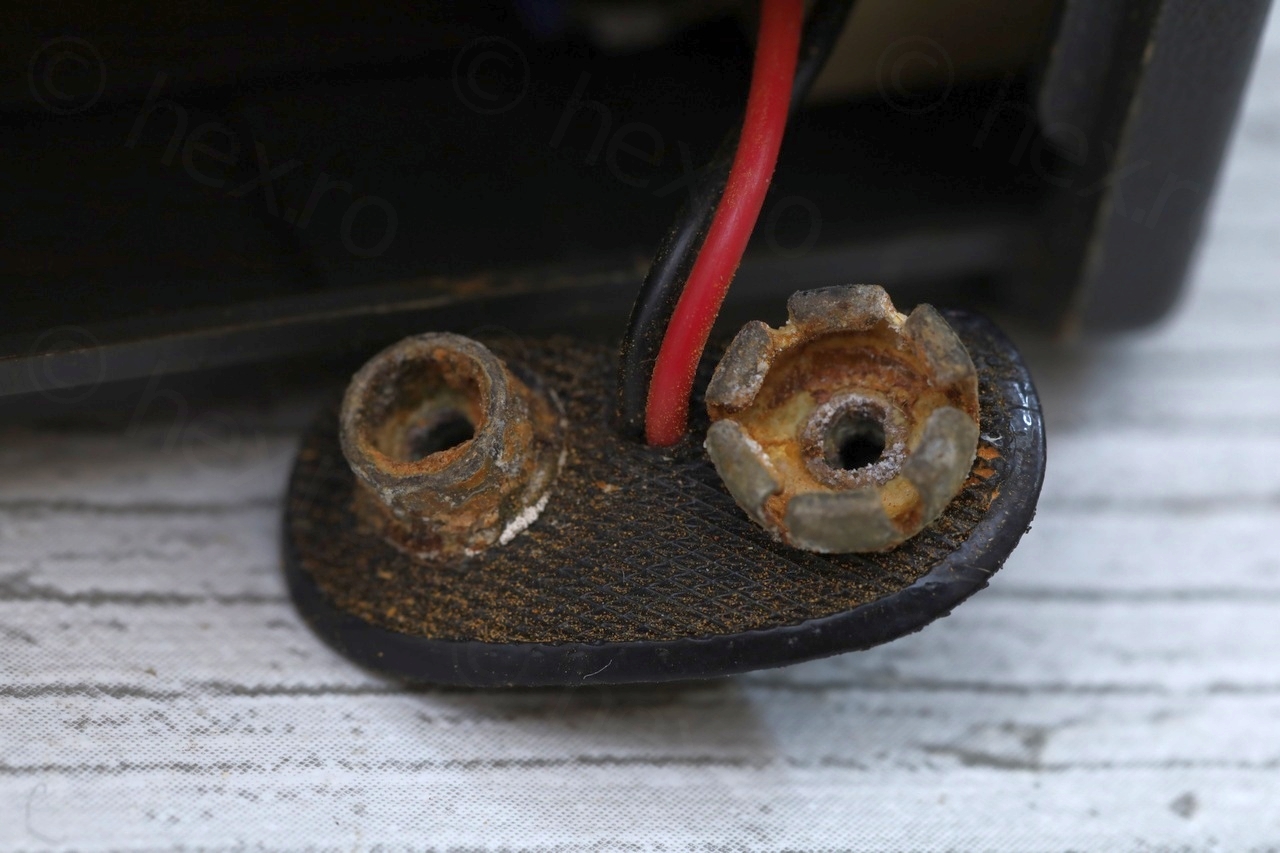

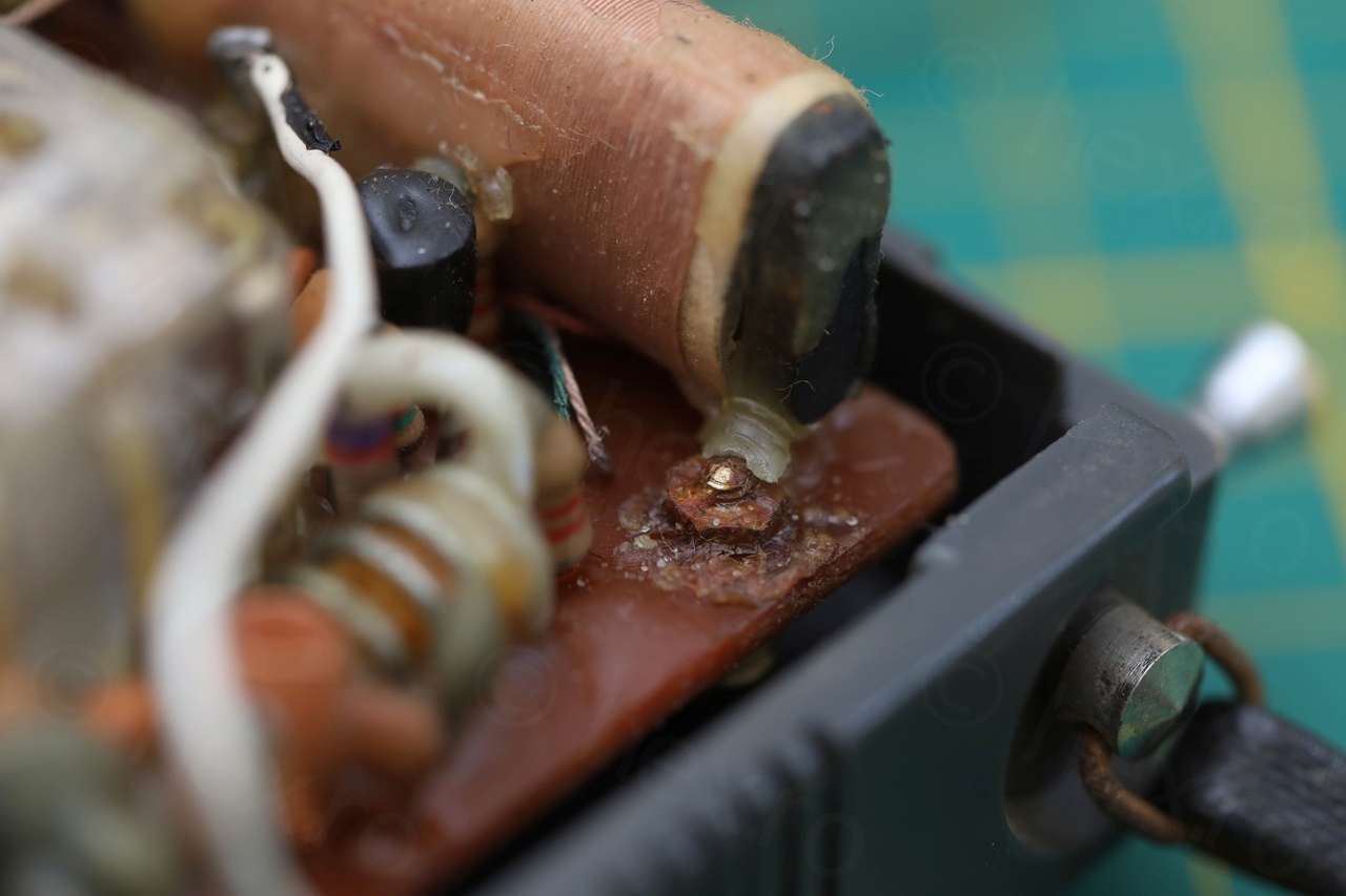
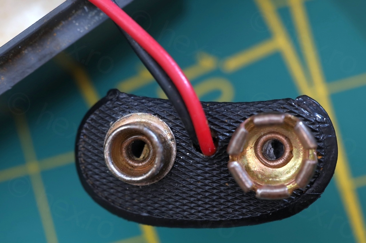
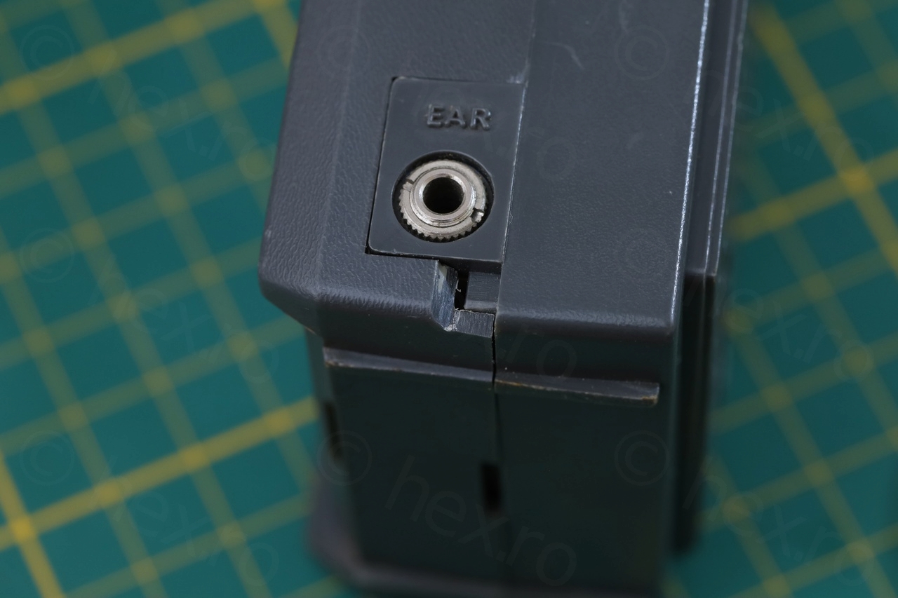
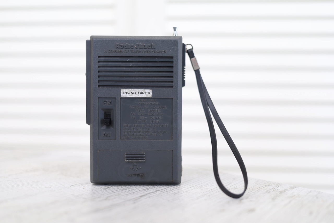
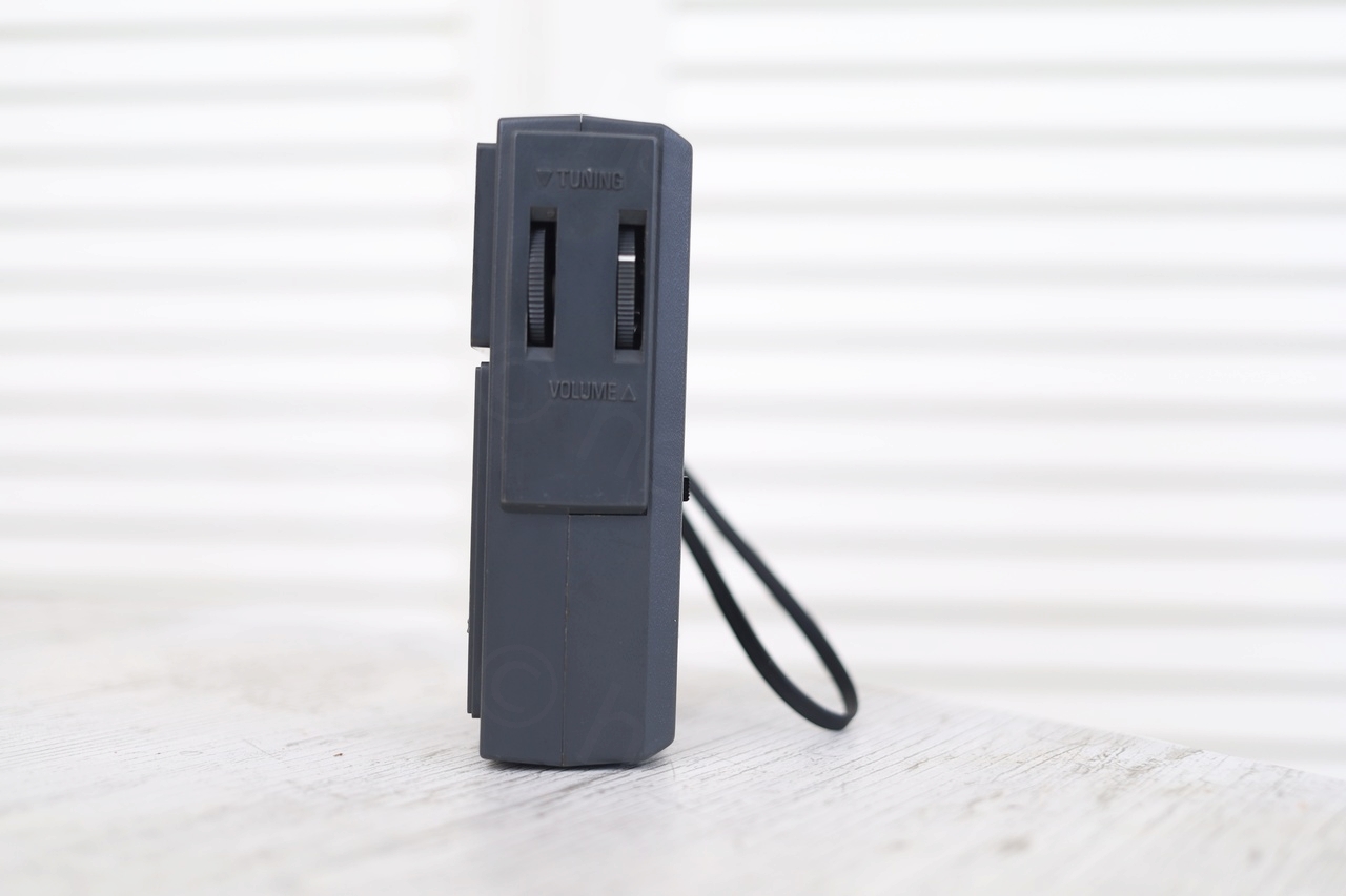
Inspecting it visually, the first to stand out was the battery holder being extremely corroded. Then one corner of the back case was cracked and missing. Also, the Tuning Knob was slipping. And in use, the Volume pot was acting in a very weird way: it was quiet the first quarter of the turn, then very loud and lots of crackling.
The most concerning was AM sensitivity though. It sounded like the radio tries to receive (sensitive and loud to the electromagnetic noise around) but the stations would come through very faint even with the volume to the maximum:
Opening up the radio
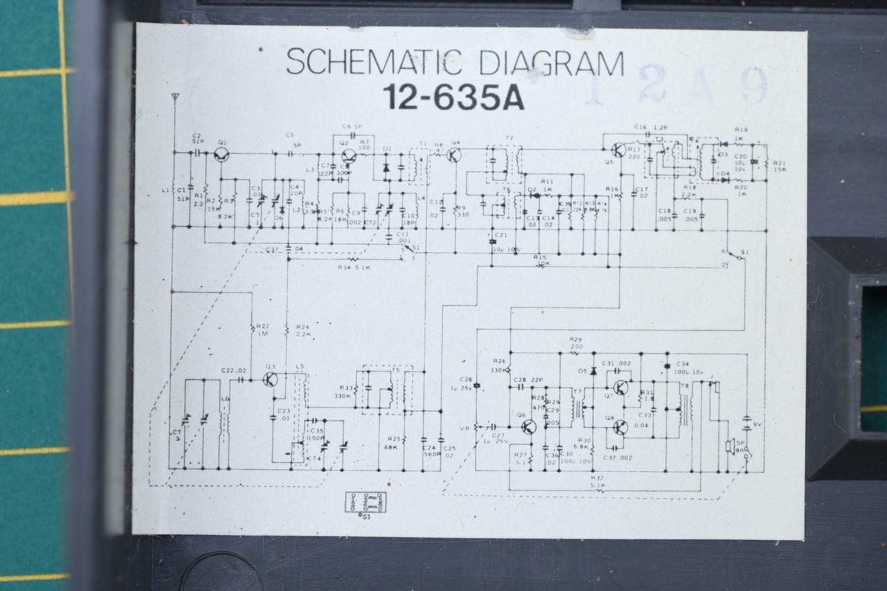
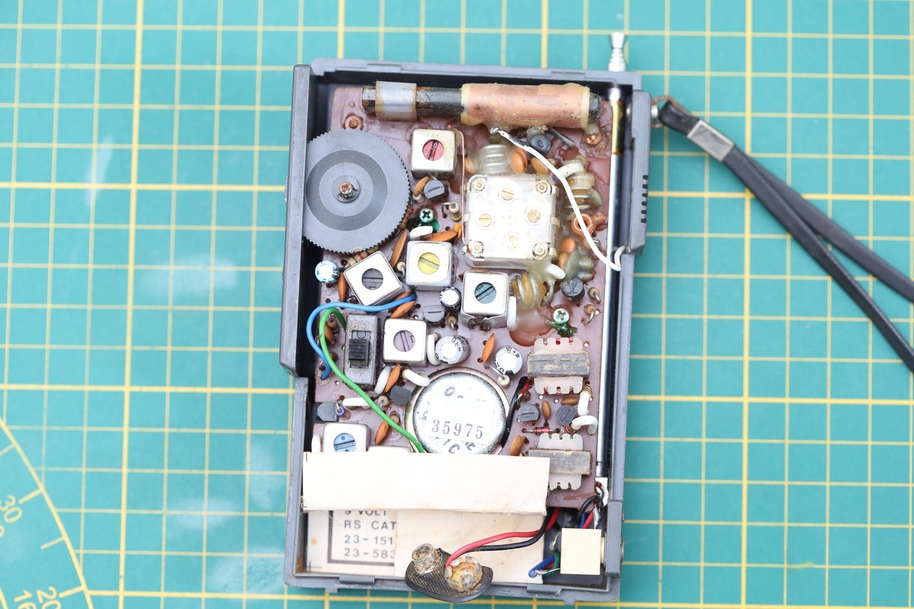
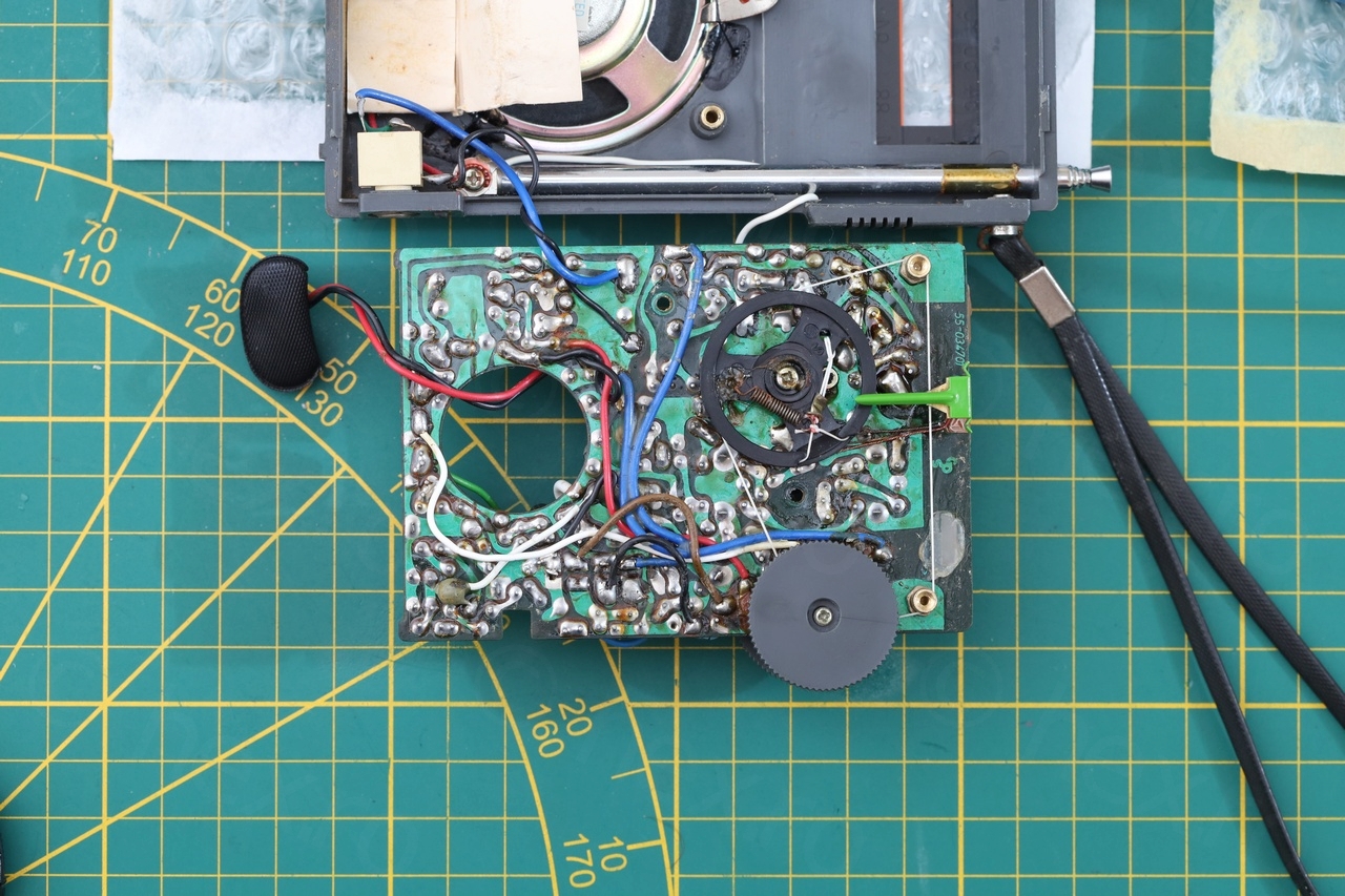
Inside I found more surprises – more corrosion, a piece of copper wire that just fell off and the schematic diagram!

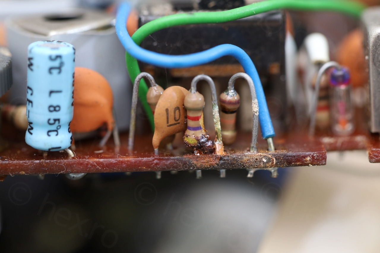
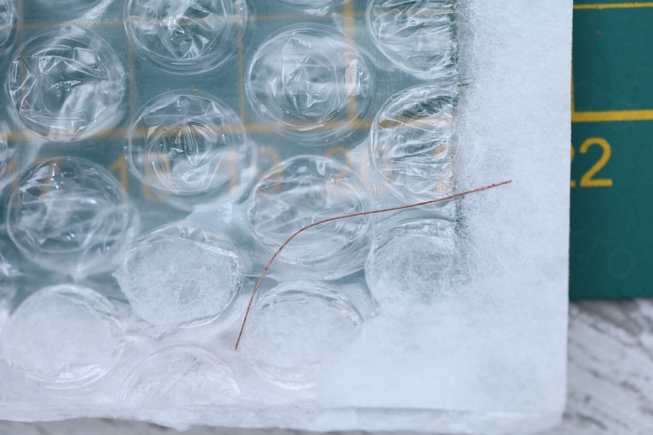
The piece of wire was puzzling. I couldn’t tell where it was from, it had no solder at either ends and the more I looked, the less it seemed that it was from the radio itself. I started suspecting that somebody else was inside the radio before ?
Volume Potentiometer
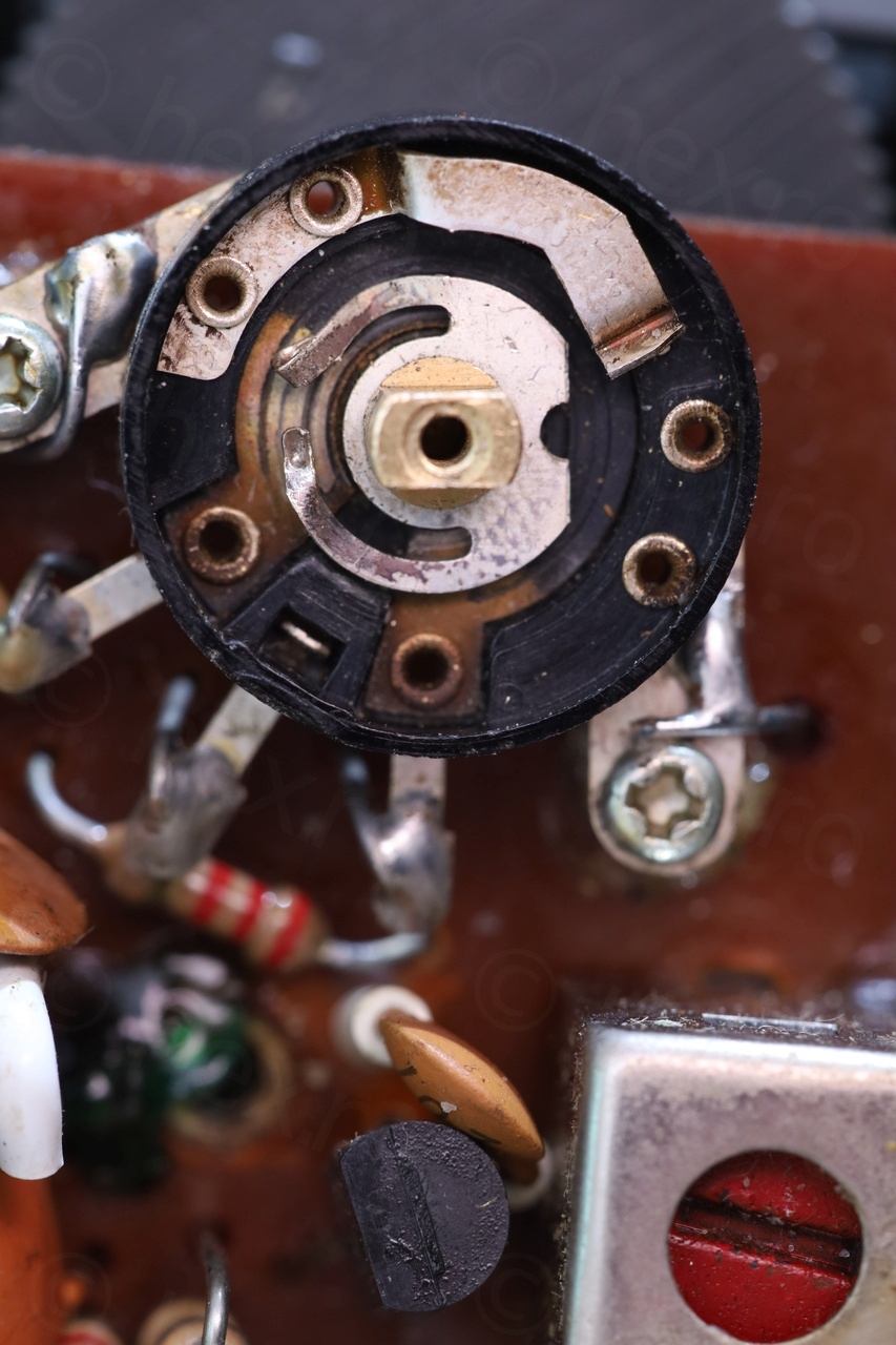
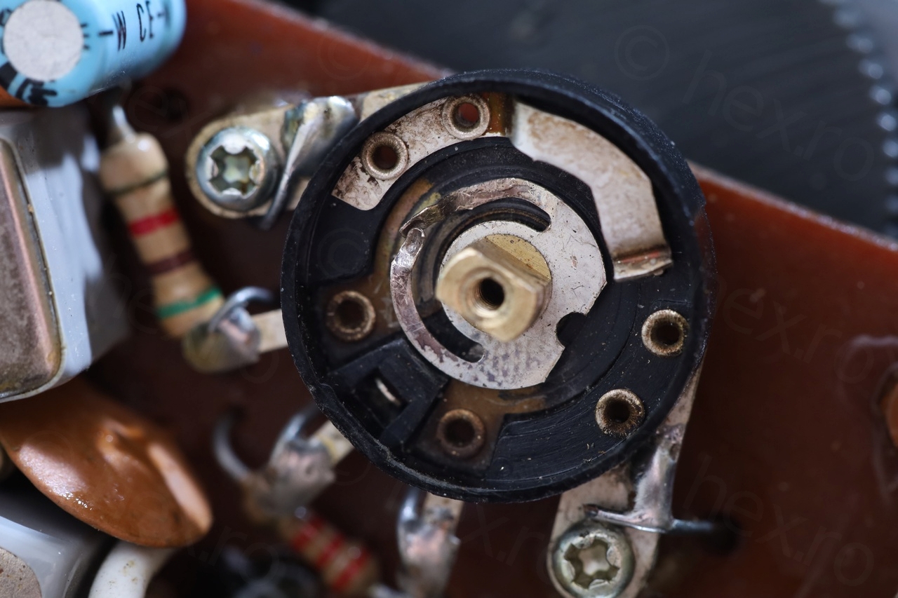
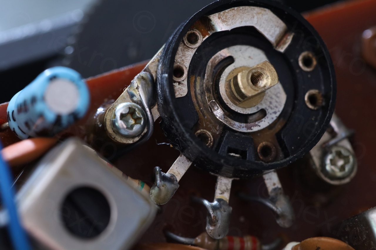
I focused on the Volume pot first. It was very annoying: either quiet one quarter / one third of the way – but then extremely loud. It was also cracking very badly, and no amount of drenching it with contact cleaner would have an impact. I decided to open it up just to check, something didn’t feel right and I had to have a look. Aha!

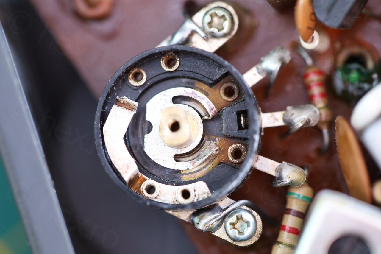


Somebody has managed to bend backwards both ends of the wiper assembly to the point where the assembly was rotated from what should have been the correct position (meaning, from lowest resistance just after turning on). The bent leads were now rubbing on the resistive element, leaving groves and chipping away at its ends as the Volume Pot was turning. This explained both the crackling as well as the loudness…
I managed to unbend the leads as best as I could, cleaned it more, and rotated the wiper assembly back into its correct position to have low volume just after turning on:
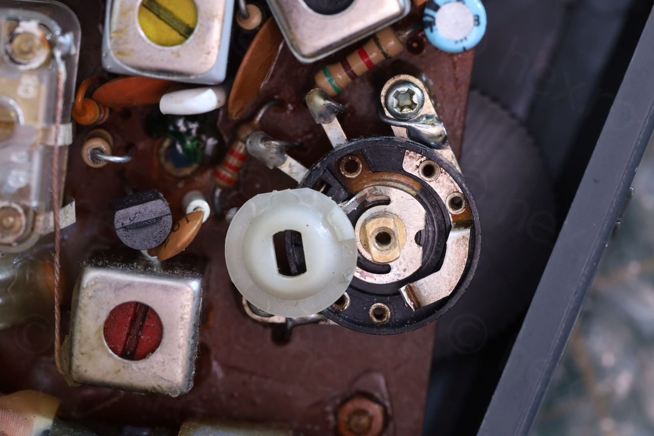
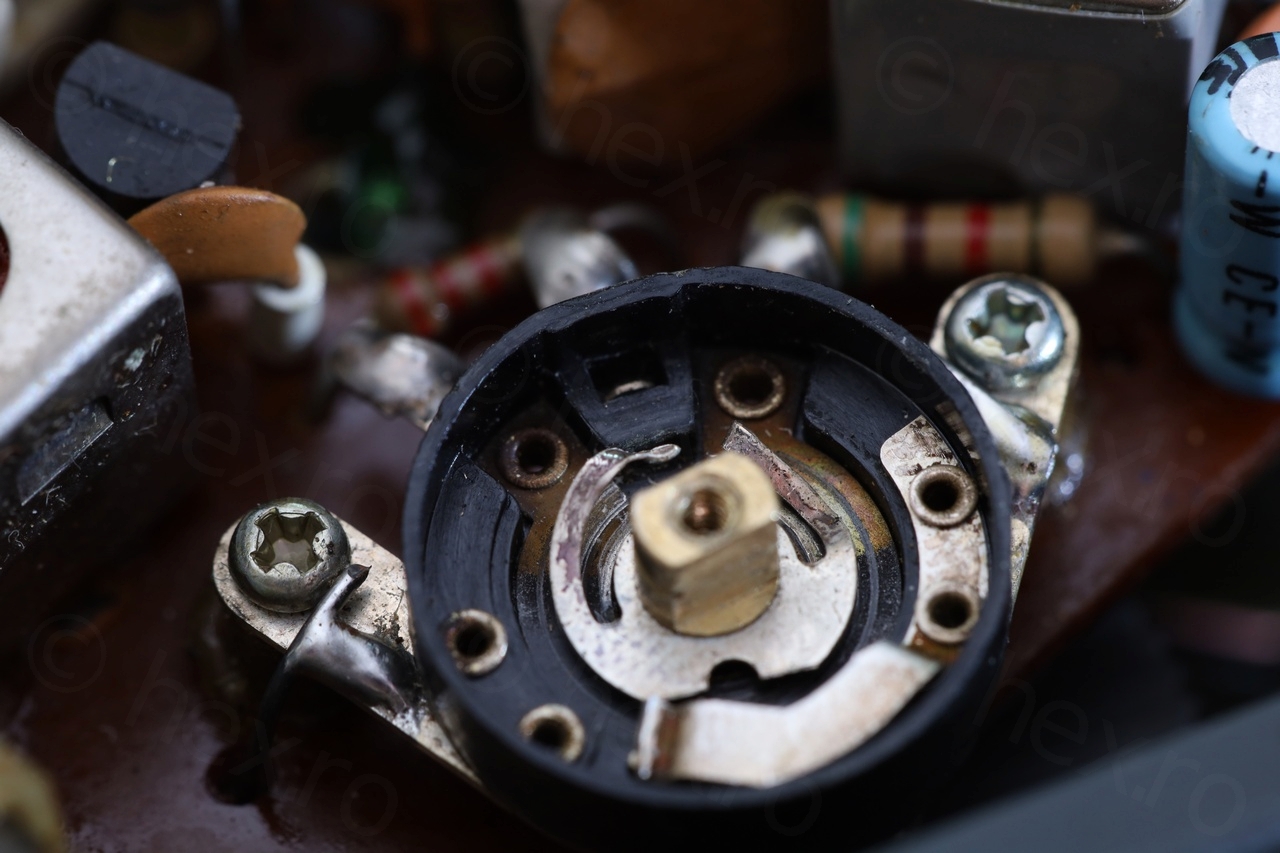

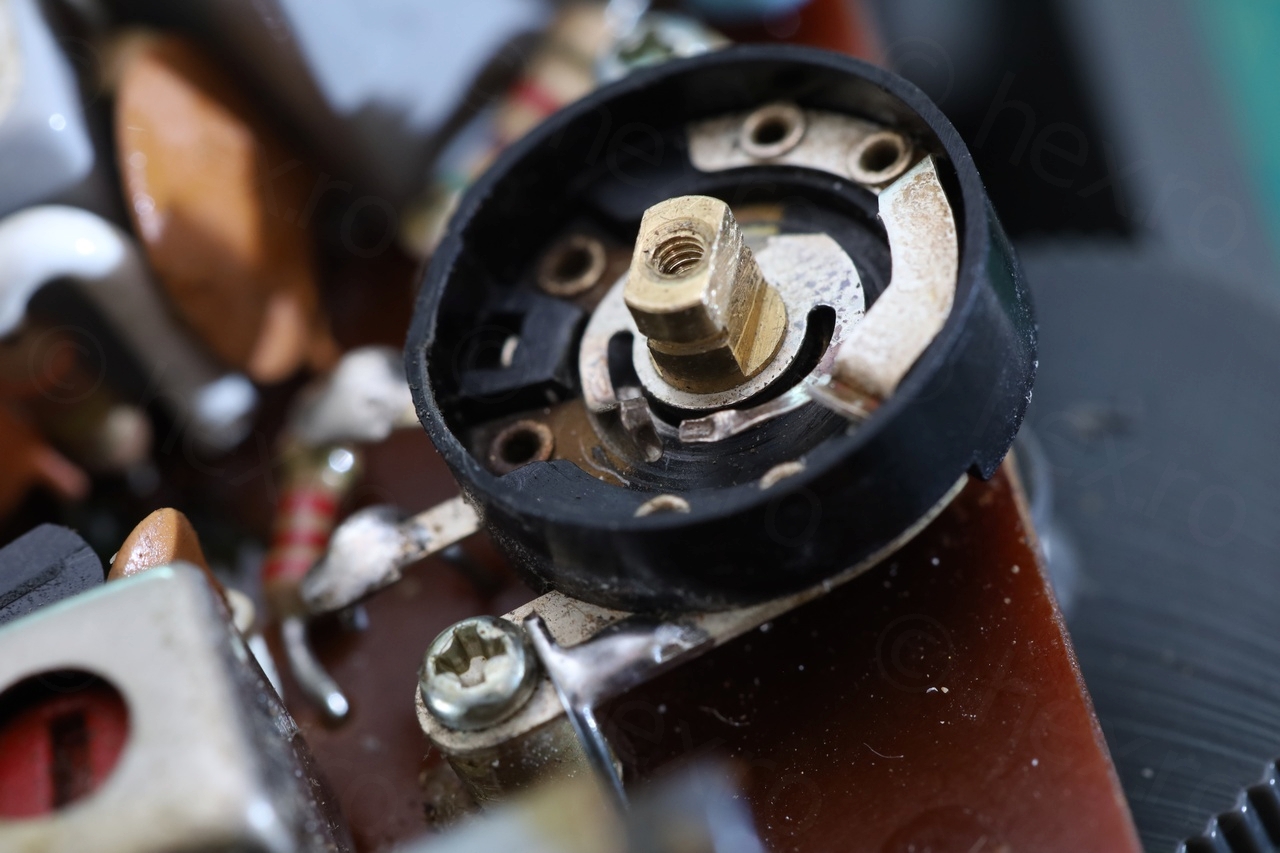

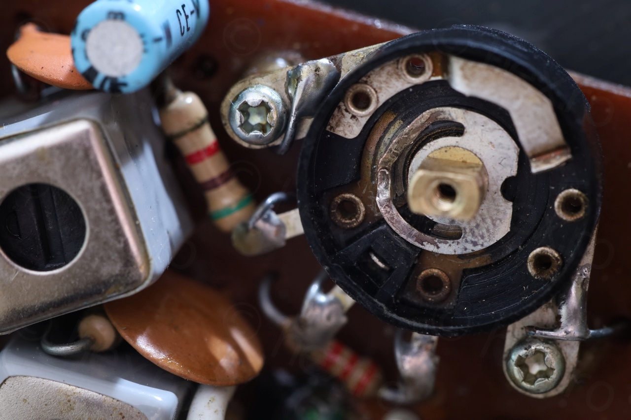
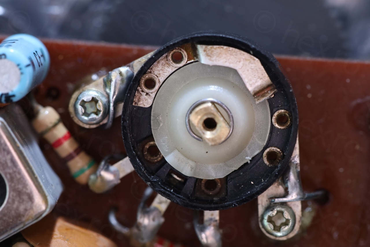

The Volume now behaves sanely but there are still cracklings due to the grooves in the resistive element. And since the ends of the wiper assembly were bent, they were actually jamming against the ends of the resistive element, which now were almost missing. So as you reach almost the maximum volume, the audio cuts away in fact.
However, I was able to salvage the potentiometer and keep the original. The restoration made it quite usable.
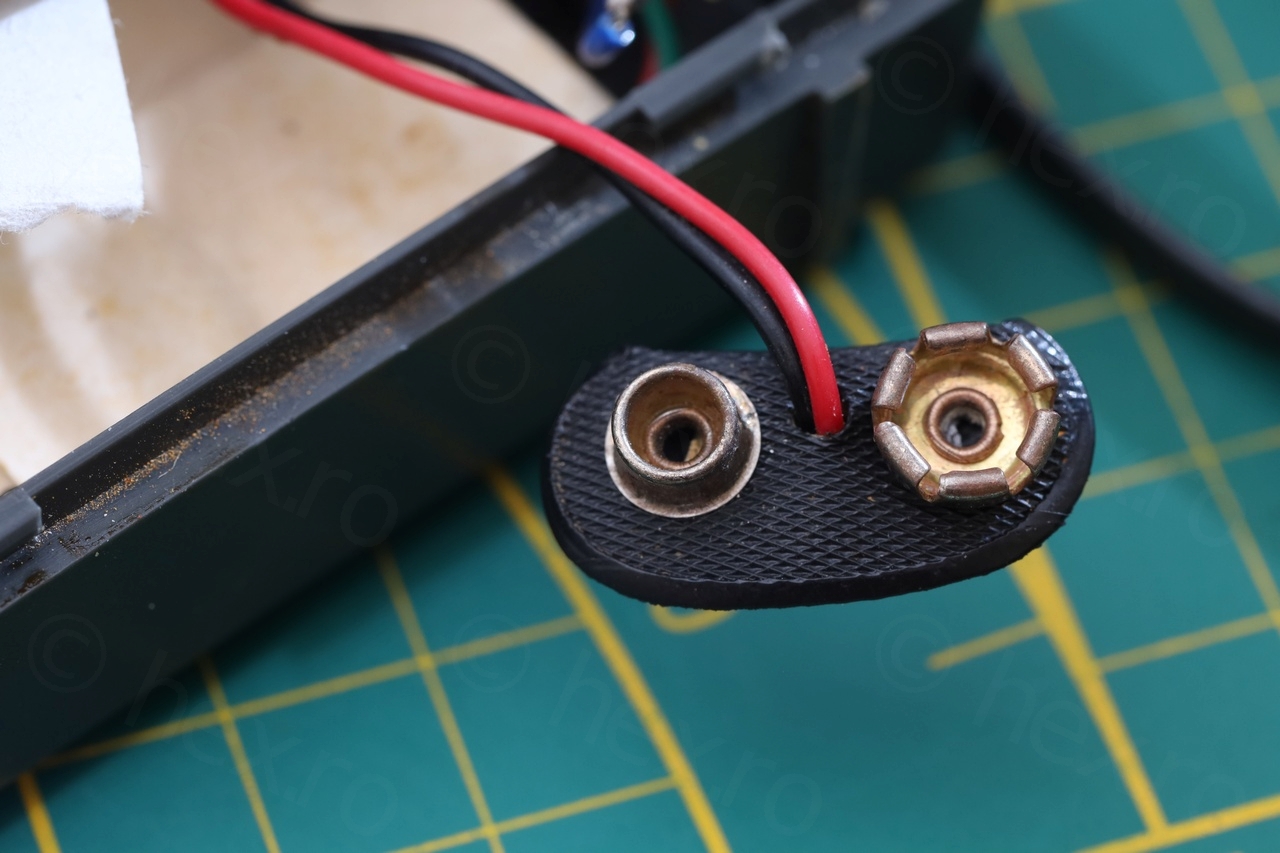
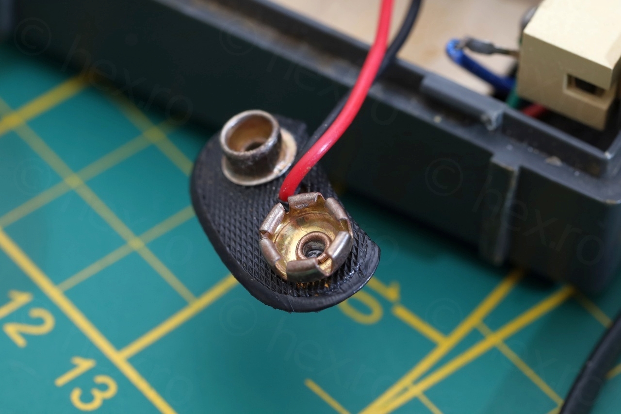
Cleaning up the rust from the battery holder
I filled a small plastic cup with vinegar and submerged the battery holder inside. It came out beautiful:
Weak AM reception
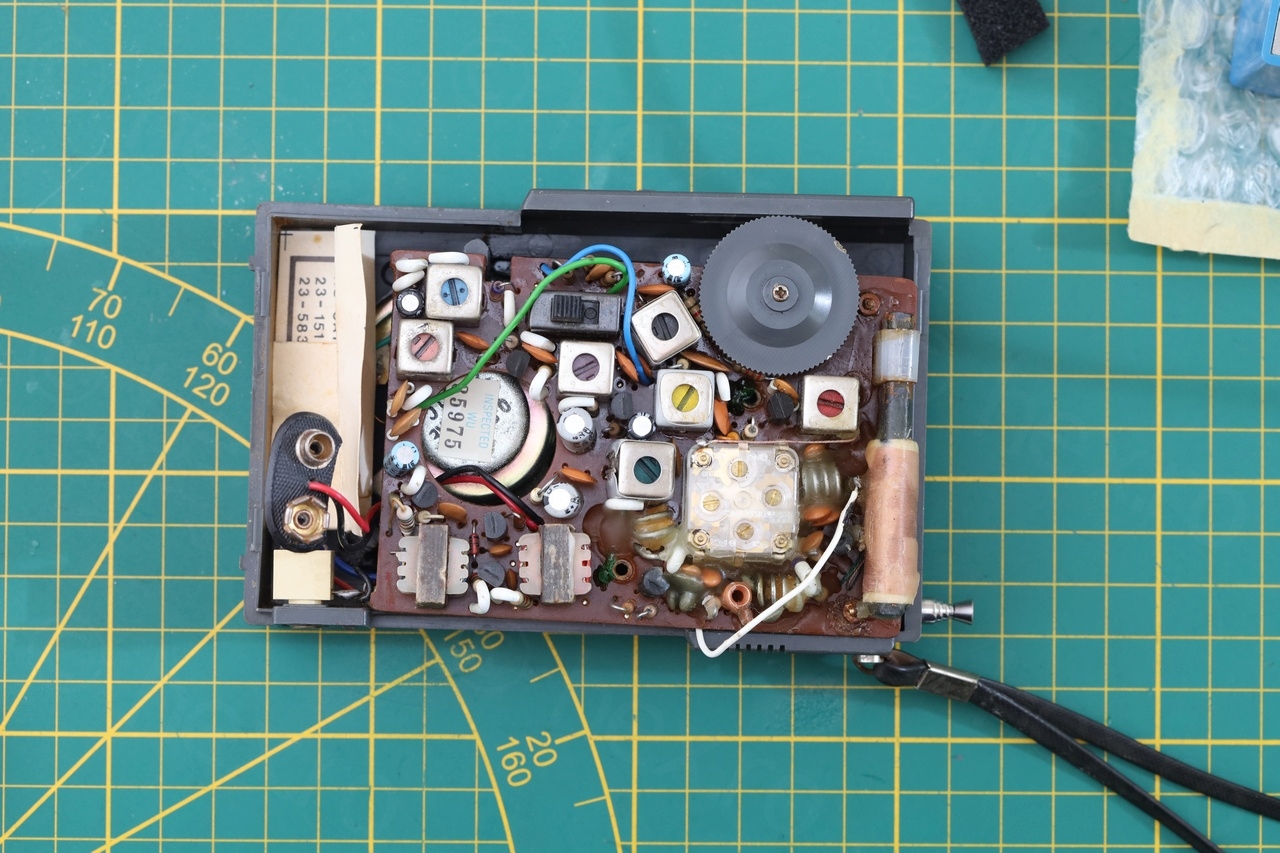
This got me stuck for a while suspecting a transistor or a capacitor. However, which one is which ? I had a hard time flipping the boards around and I am always afraid the old wires would break (battery, headphone, antenna). So I took two photos, one of the back of the board and one of the top, and aligned them in Gimp. Then, flipping the board around was just a matter of hiding a layer.
And cross checking with the schematic, I was able to identify the key components in the circuit, including the AM part. I didn’t try to identify all though, and I hope is correct:
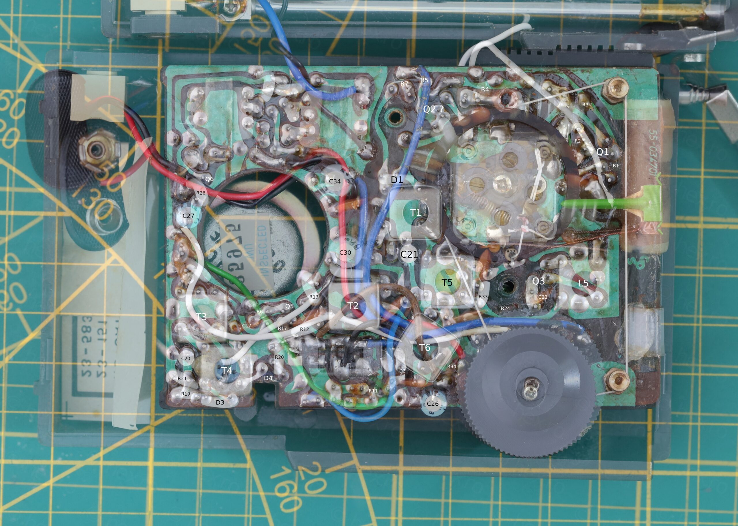
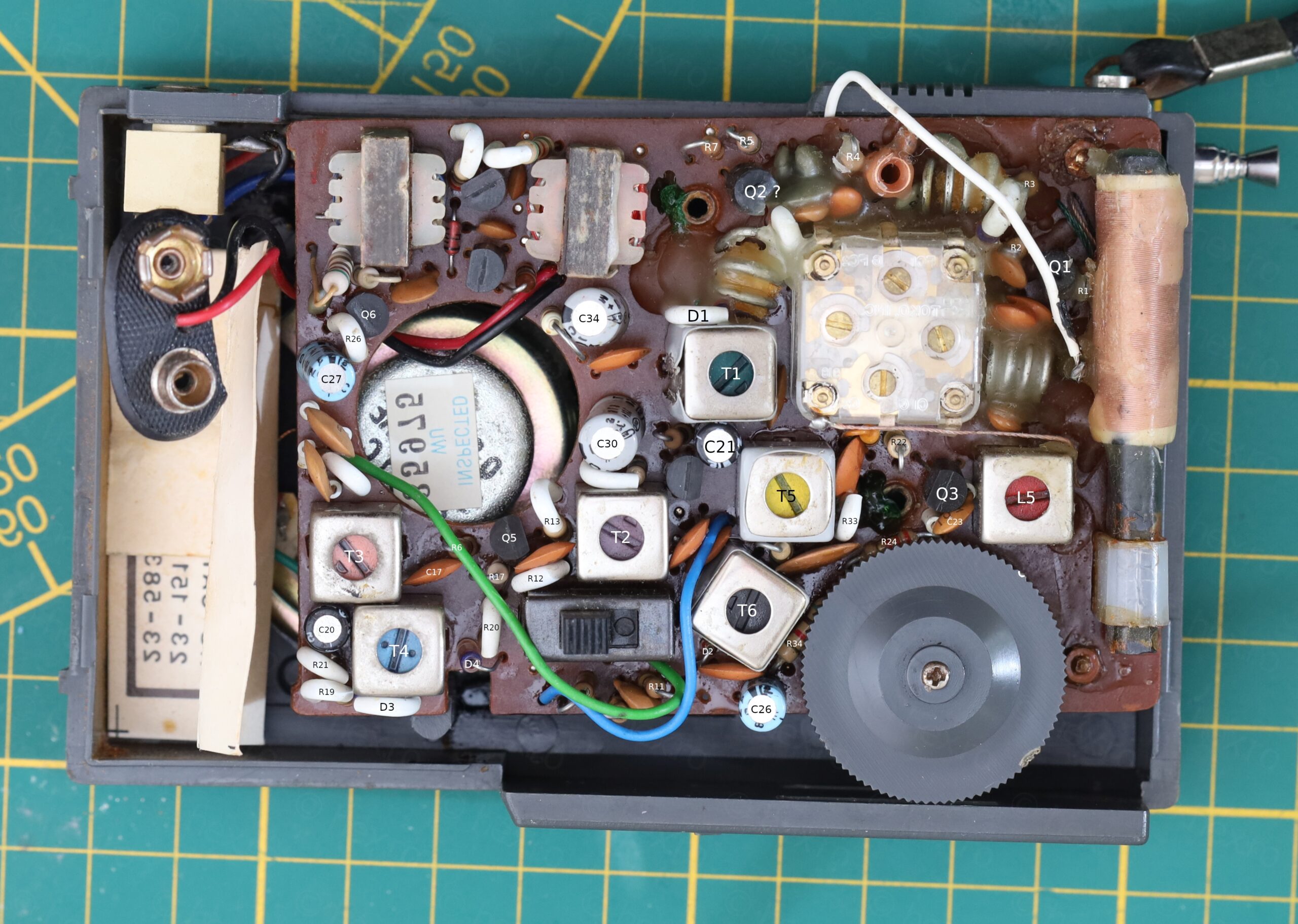
While trying to come up with the layouts, I discovered some inadvertences in the small tiny schematic compared to the real board:
R1 = 2.2K (by color) but is 2.2 in schematic
R2 = 820K (by color), marked 330K in schematic
R22 = 680K (by color), marked 1MΩ in schematic
Voltages on Q3 were right:
Q3 is NPN, Vb = 5.18, Ve = 4.76, Vc = 9.13 (AM)
Vb = 8.53, Ve = 8.53, Vc = 9.05 (FM)
Q3 is an EBC NPN.
After cross checking all capacitors (by paralleling a good known one) the only remaining thing was to try to align the radio. And I discovered it was actually very badly aligned, T6 was way off. This restored the radio’s AM sensitivity.
And what about the broken corner ?
I decided to 3D print the little part that was missing from the case:
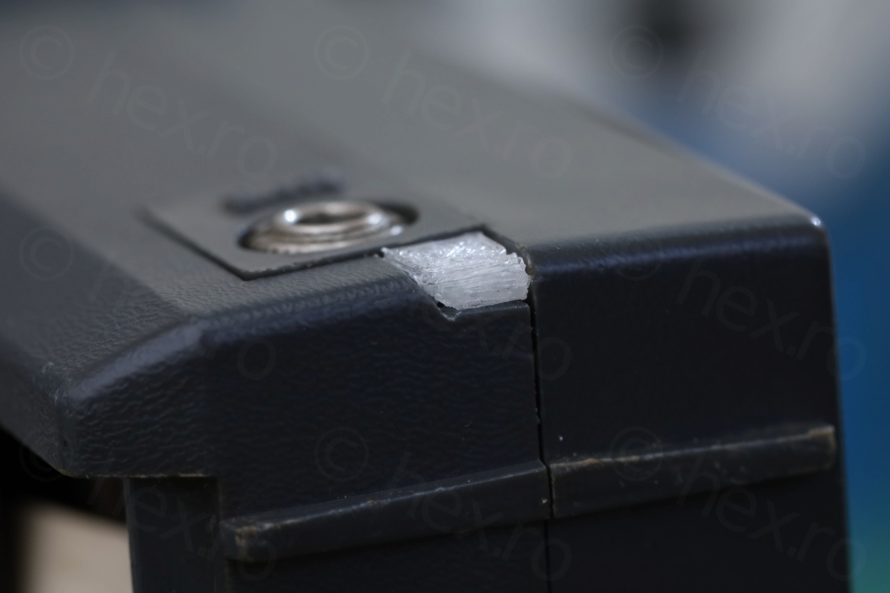
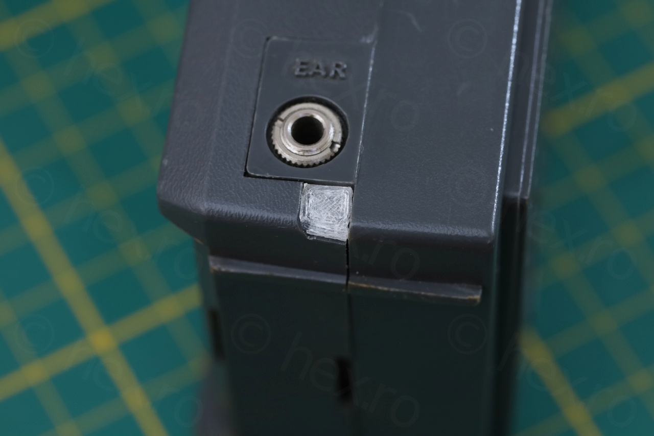
I don’t have a dark gray paint yet to paint it over, but at least I feel the radio has some dignity back!
A video with it in action:
There are still some cracklings (as the Volume pot was found partially destroyed inside) but AM / FM sensitivity work. There are no local AM stations in Belgium anymore, but at night some UK, Italy, Spain, etc… stations come through decently.
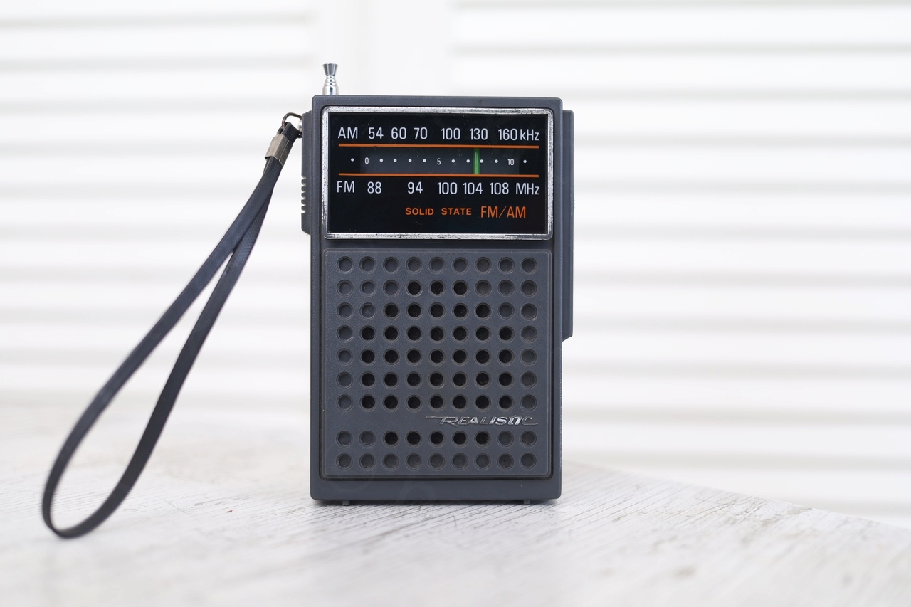
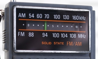
I also noticed a little “bug” in the scale display, they “ate” one Zero from the AM band frequencies:
A small old school interesting radio made with Silicon transistors :). The fix for the slipping Tuning Knob was sewing machine oil on the moving parts, they were almost stuck.
Leave a Reply