

Introduction
I found this mini CRT inside a JVC GR-303EG Camcorder camera that I got at a flea market. The CRT has an additional marking, Citizen 2400-32 – as you will see below.
Camera
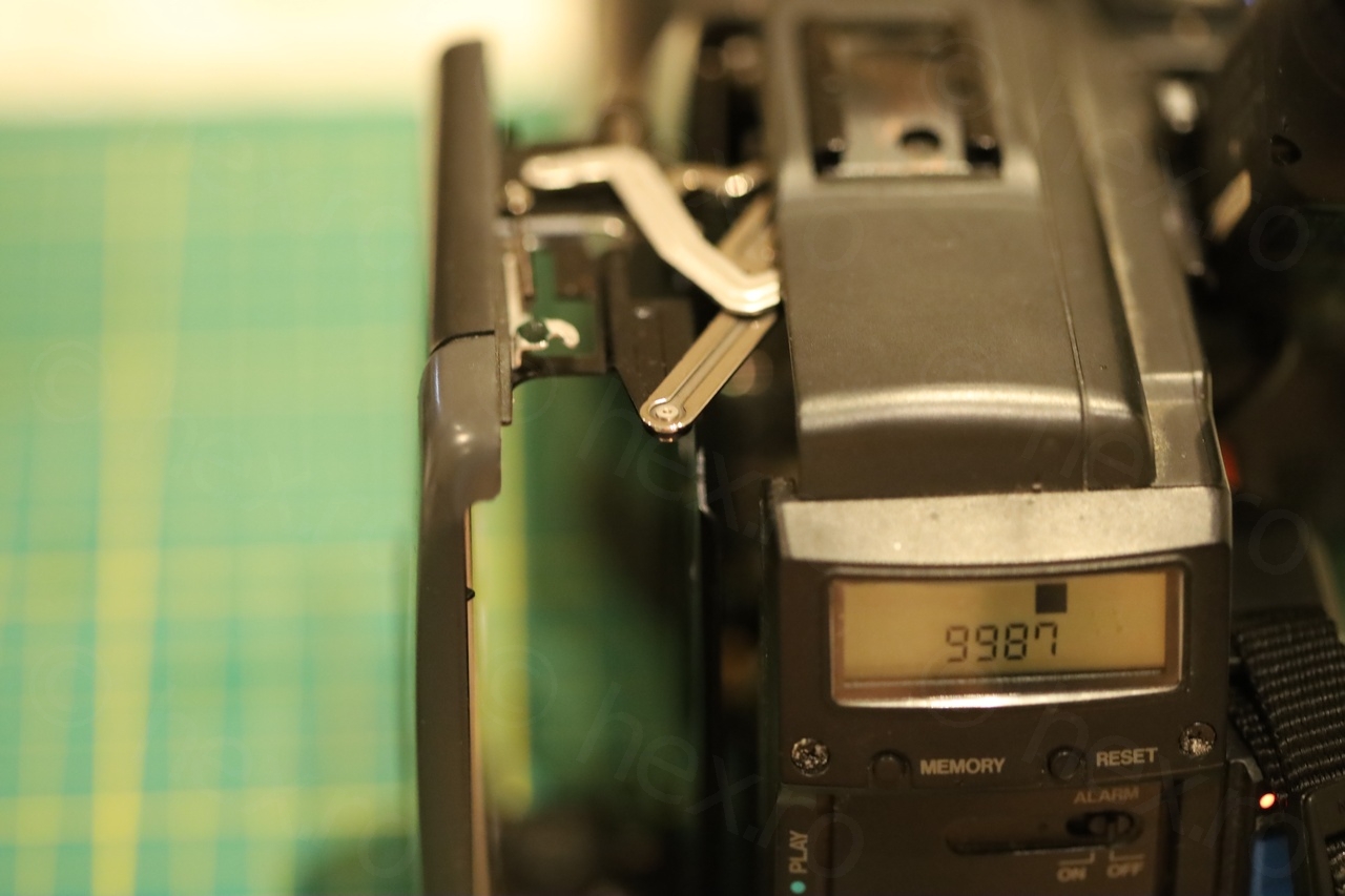
As opposed to some other ones, this camera does power on (although nothing is displayed on the screen). But this gave me hope that the EVF unit is working without having to swap dead electrolytic capacitors.
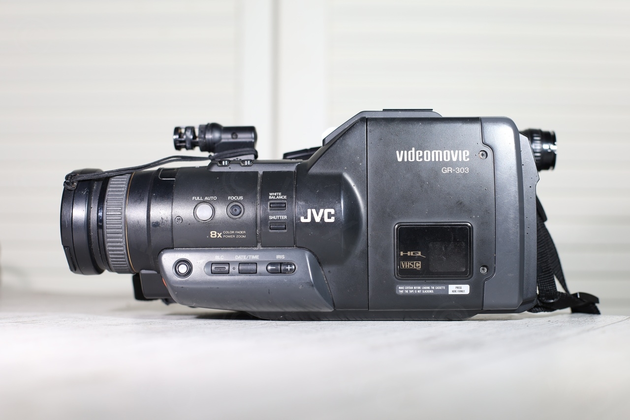
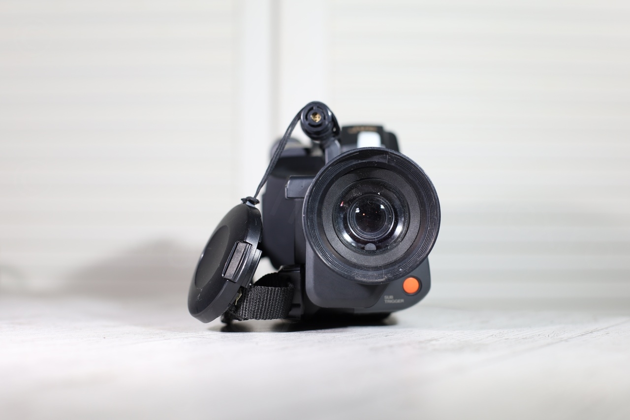
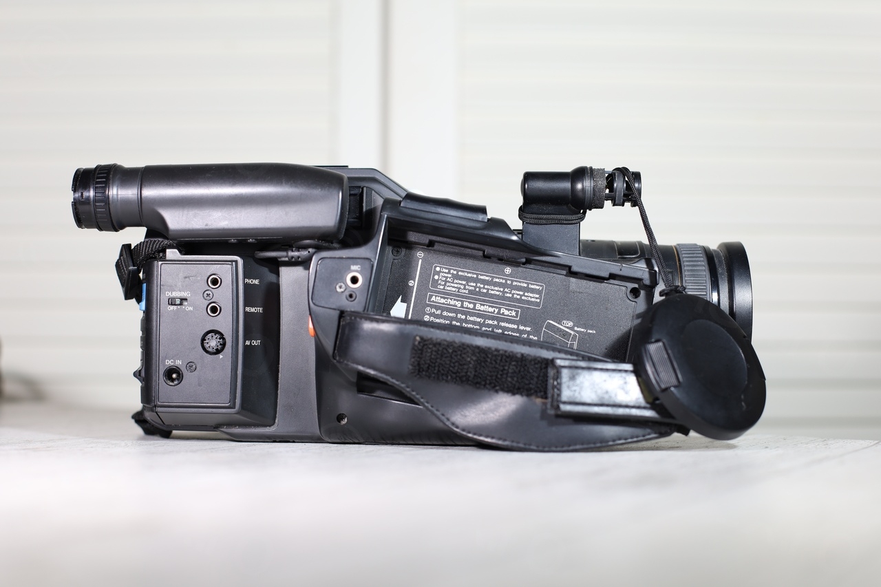

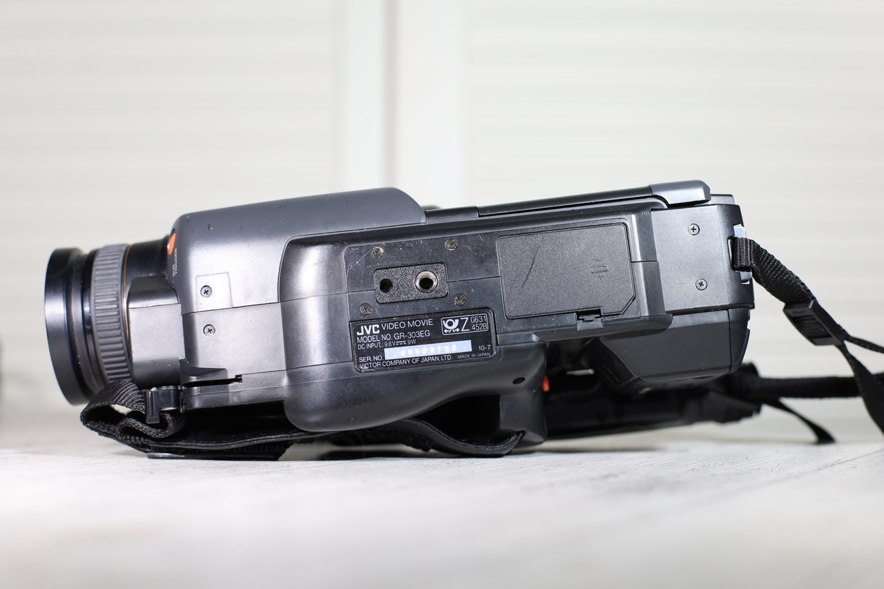
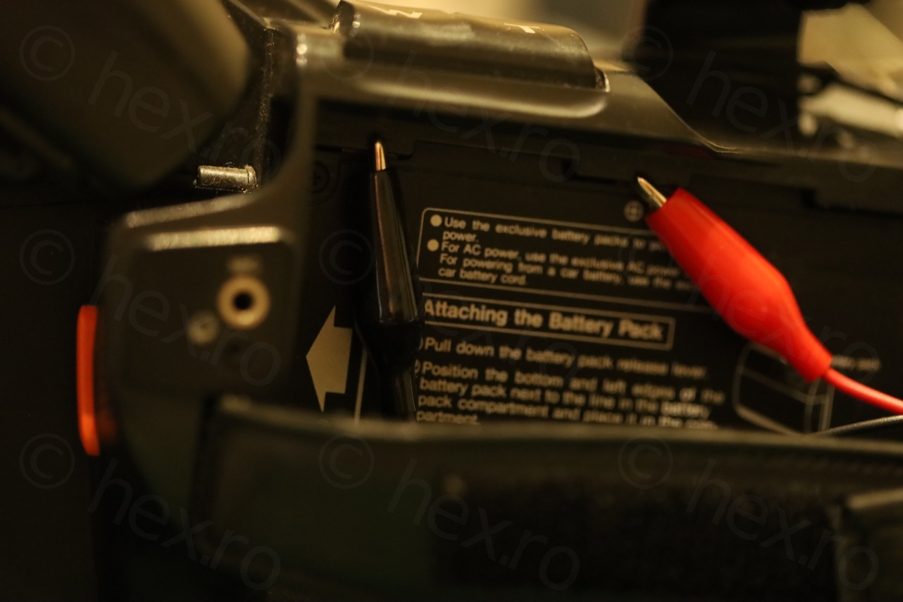
It came any accessories, for example a battery which may have the voltage indicated on. Luckily there is a marking to the side about the expected voltage in, 9.2V. Thus, I decided to power it on just to see if there’s any life and if the EVF unit lights up:


Opening up
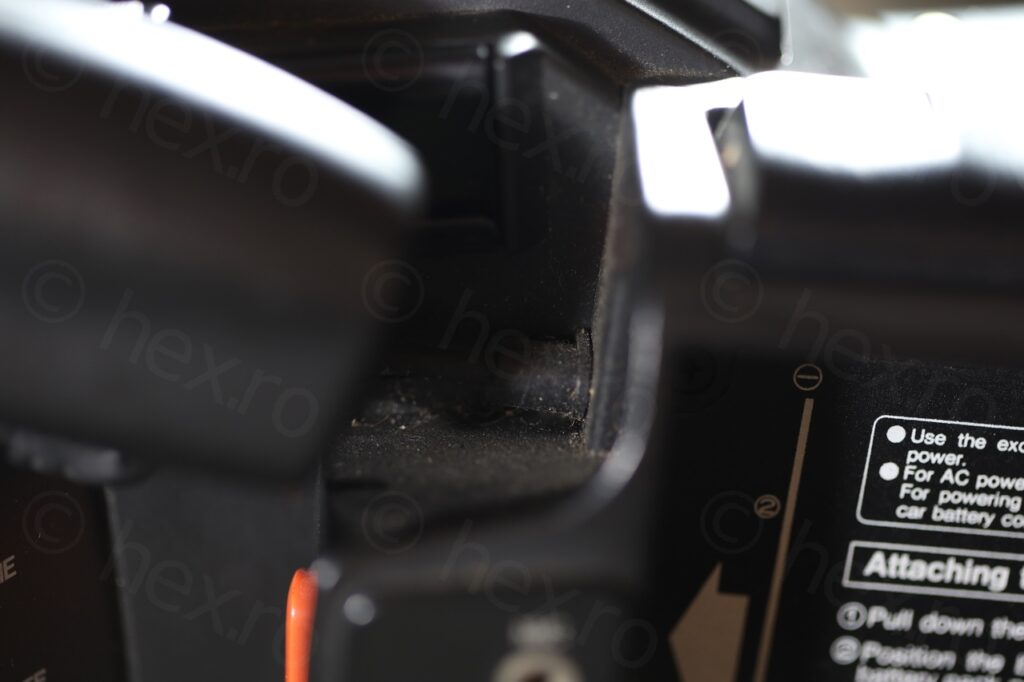
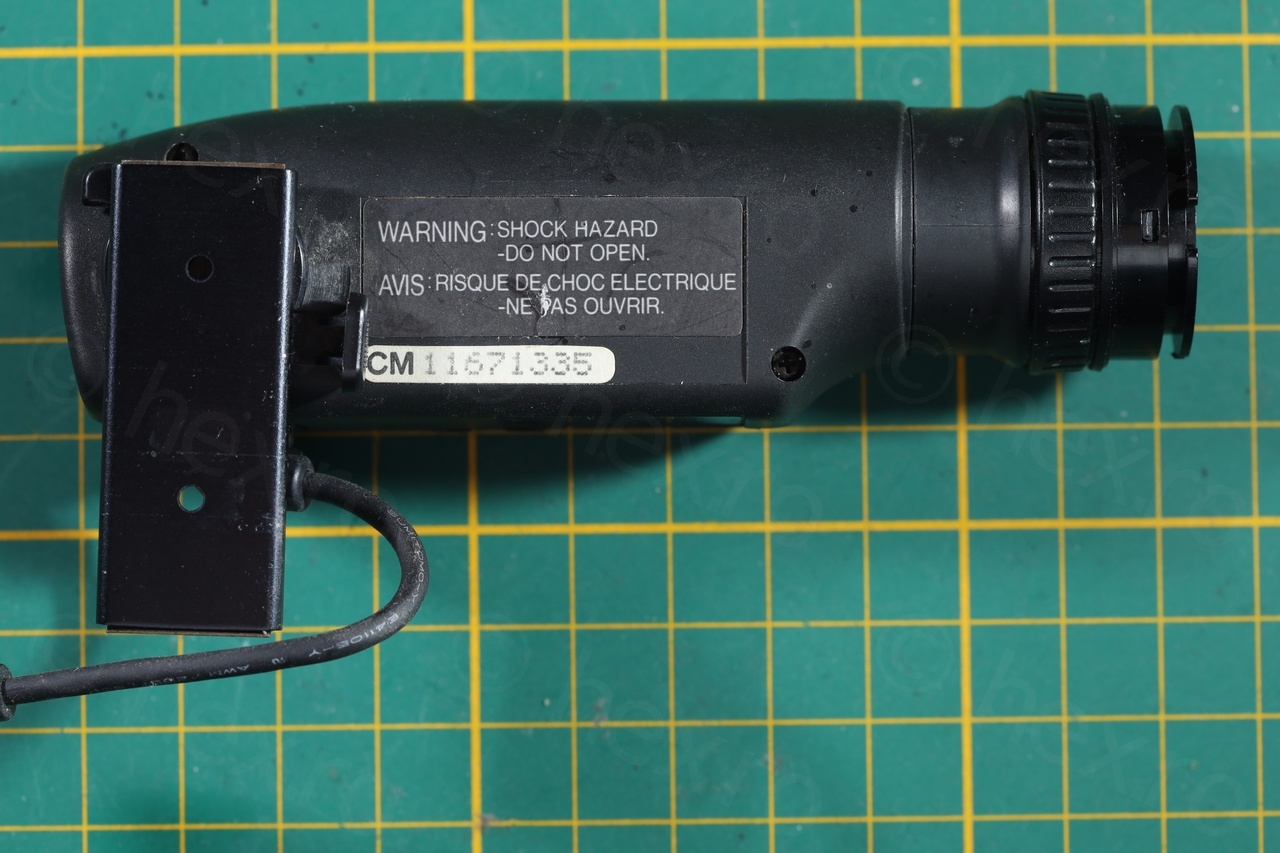
Even if there is a visible wire from the EVF unit back to the body of the camera, it is not a cable that you can unplug. It goes directly in through a rubber grommet:
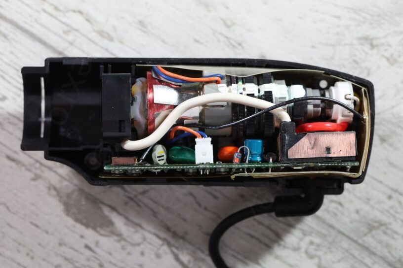
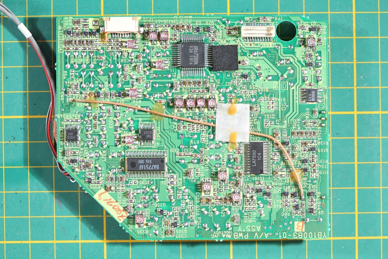
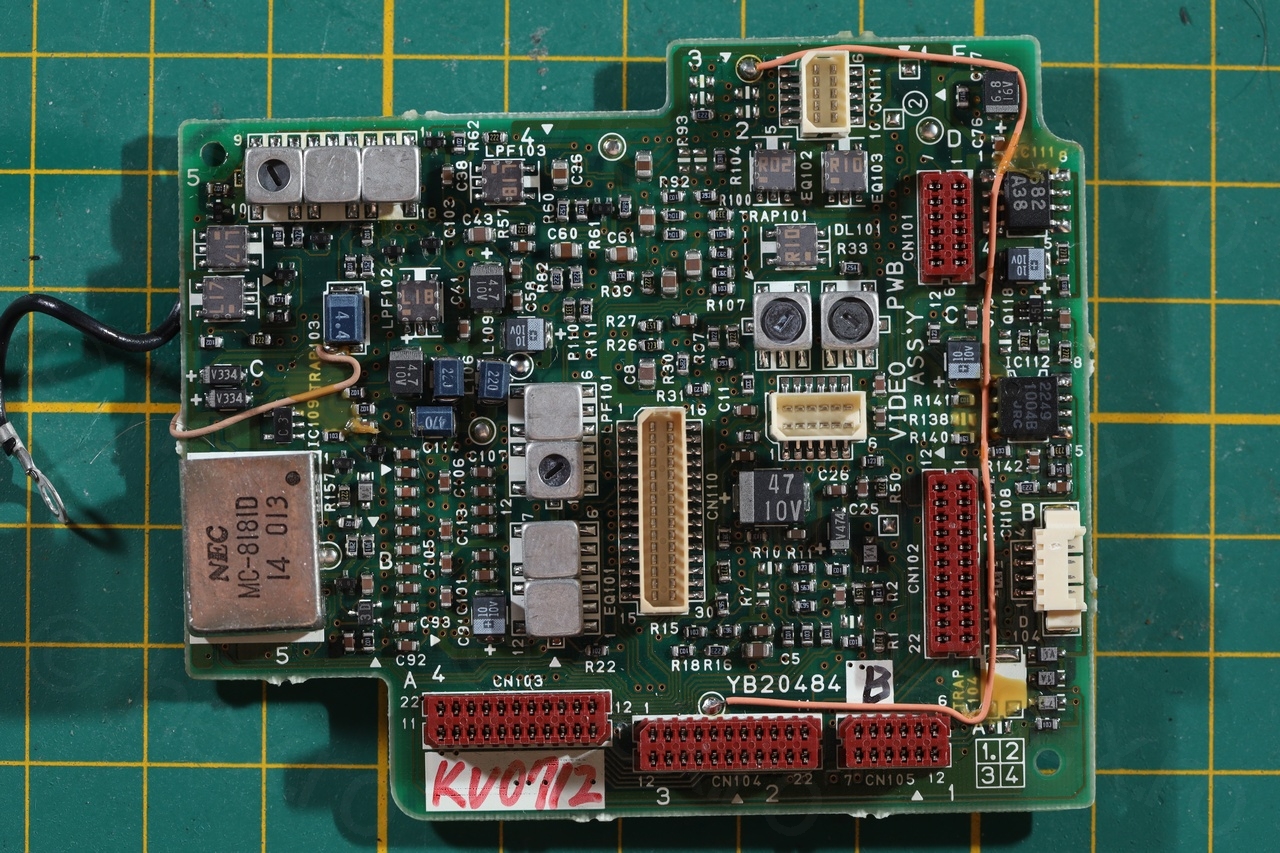
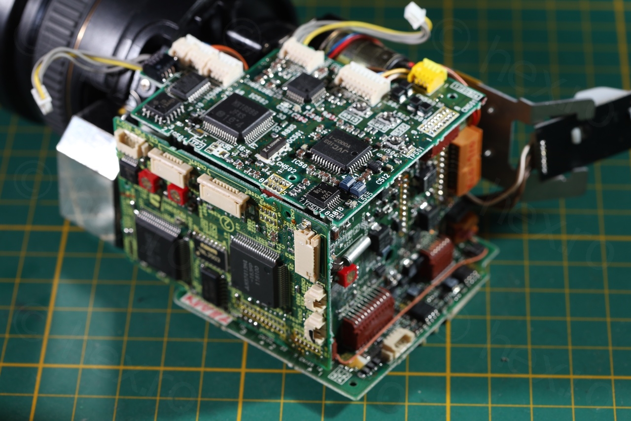
To test the EVF, it feels better to de-solder the connector plug (somewhere inside the camera) than to cut the wires (or worst, soldering directly on the driver board!). So I proceeded to open the camera and the insides looked nice. Not too many capacitors (although few seemed leaked) and few bodge wires that were properly secured to the boards:
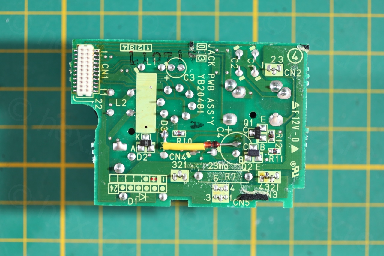

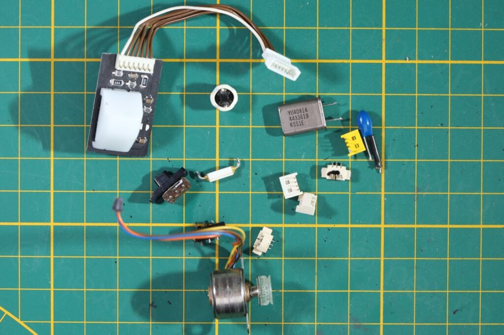
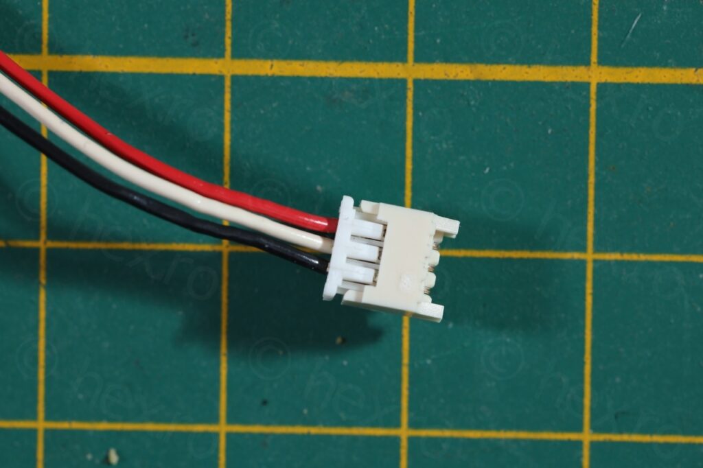
Part of the fun of dismantling is that some rare parts can be salvaged. I kept a 4433613 Hz quartz, an inductor, few connectors including the 3 pin one used by the EVF, the white balance sensor, the Autofocus motor, 2 sliding buttons and a 23mΩ resistor! (the square looking one in the center of the photo):
EVF Unit
This was the simplest ever EVF unit to get working. It has 3 wires only (GND, VCC and Video In) although, a little notice on the side of the CRT should not be missed: it needs 8V DC.
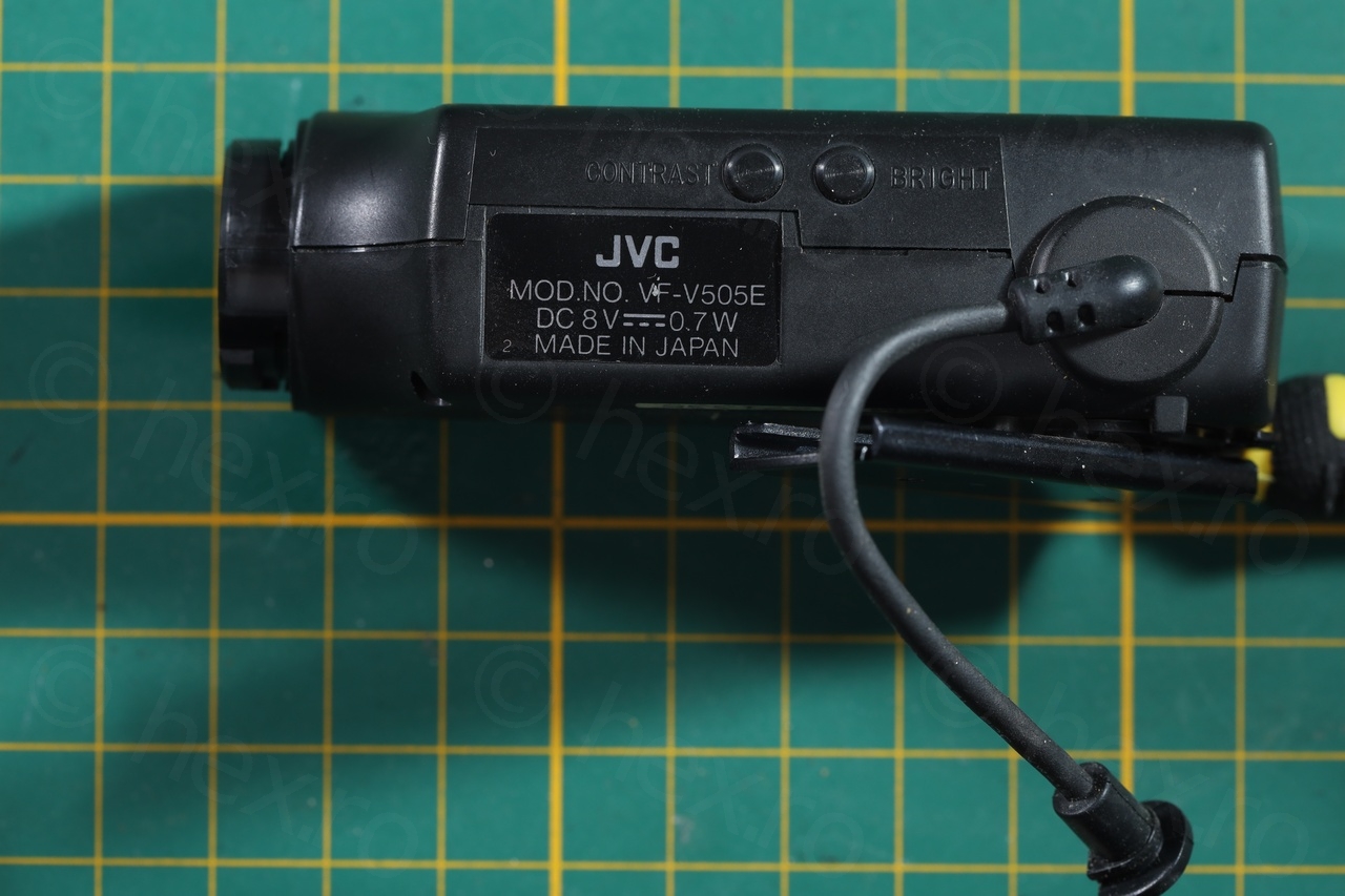
Unfortunately the rubber eye piece was missing, but it doesn’t matter if the CRT is working 🙂
Proceeding further with the dismantling of the EVF unit, I found an AN2512S driver IC and a Citizen 2400-32 / MO1KKD70WB tube.

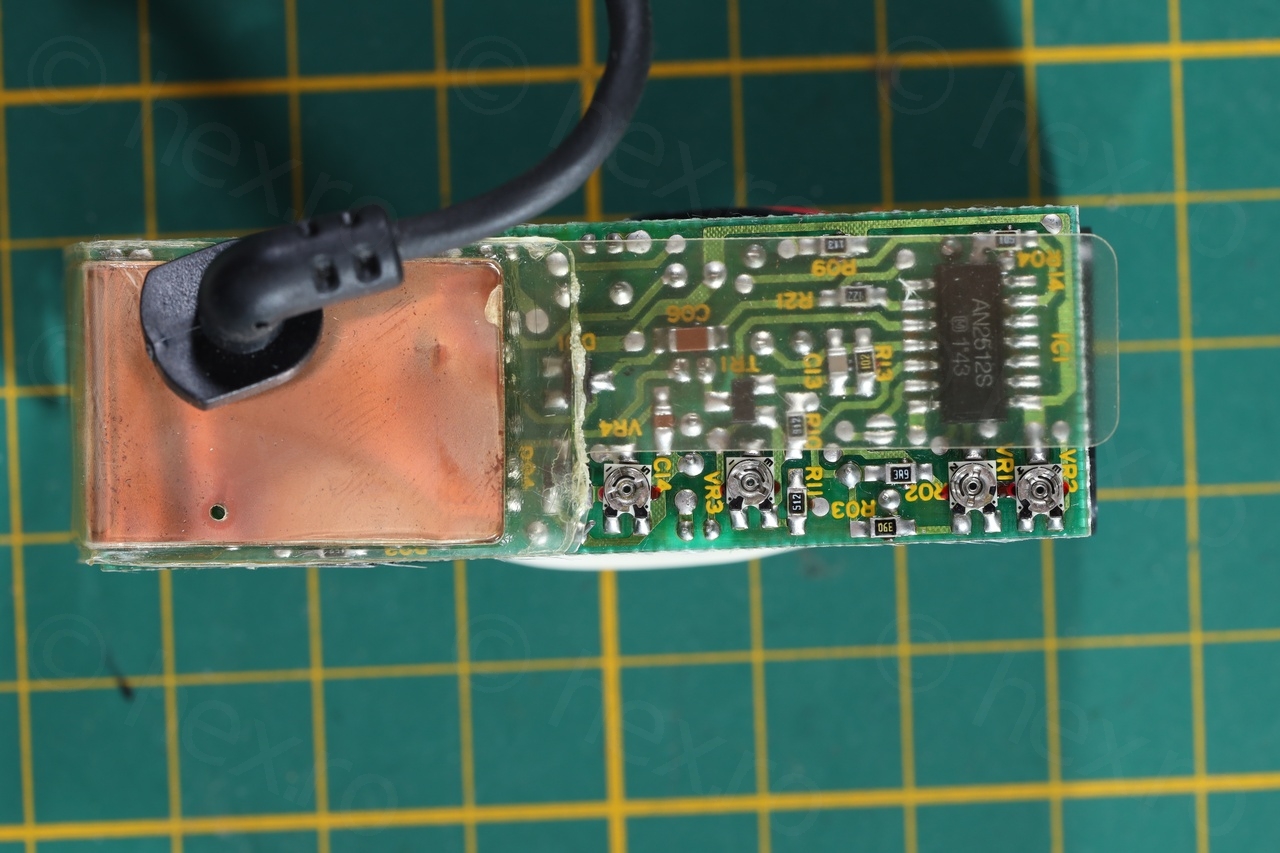
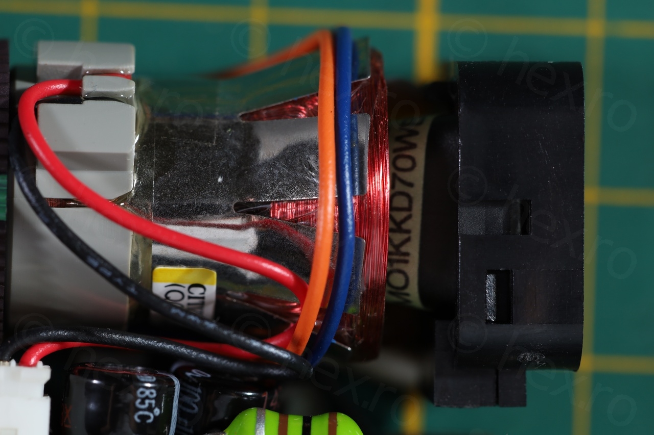
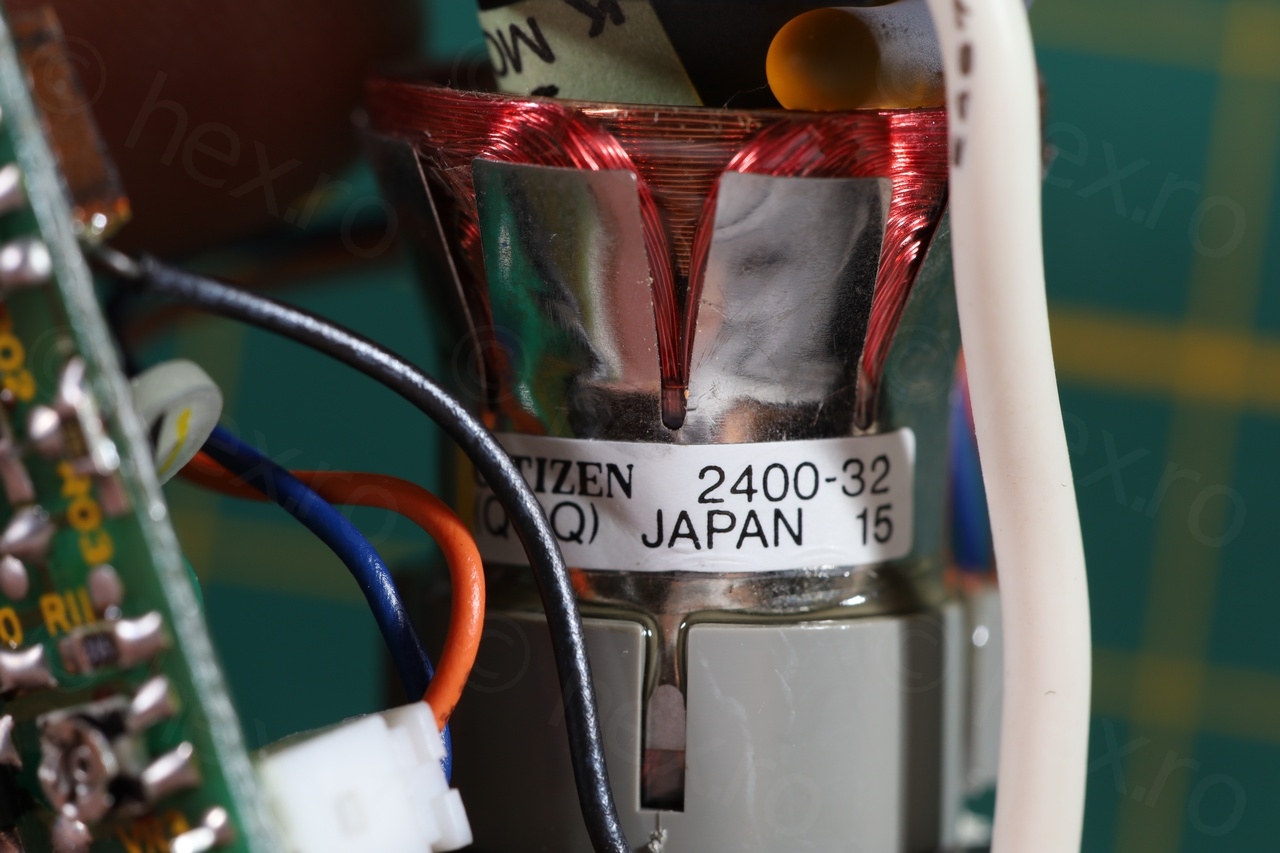
The next step was to identify the signal pins, GND is almost always directly connected to the FBT transformer case, and the first time you check, the VCC just beeps shortly when probed with the continuity meter (due to a capacitor between VCC and GND which is charging quickly).


The mini CRT works – and, as written on the EVF unit, the sharpest in my case was when it was powered by 8.2V.
Leave a Reply