Introduction
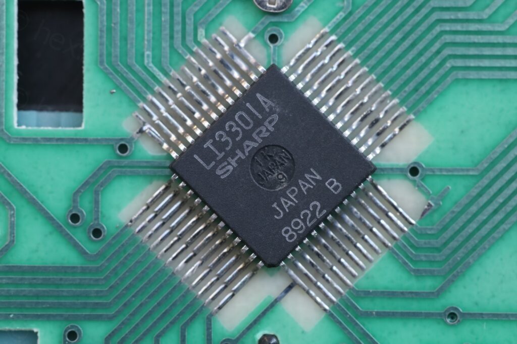
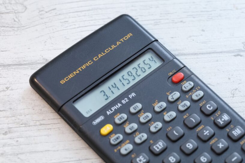
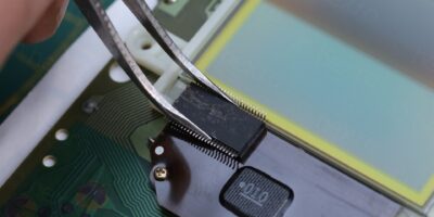
The MBO Alpha 82 PR is a programmable 10 digit calculator, powered by two LR44 / AG13 batteries, based on the Sharp LI3301A CPU.
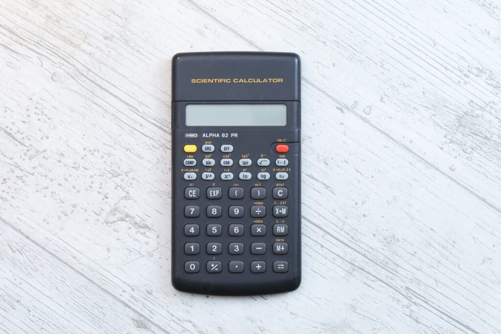


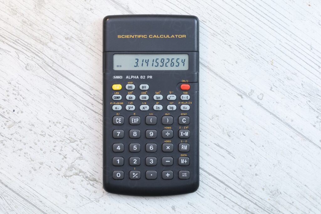
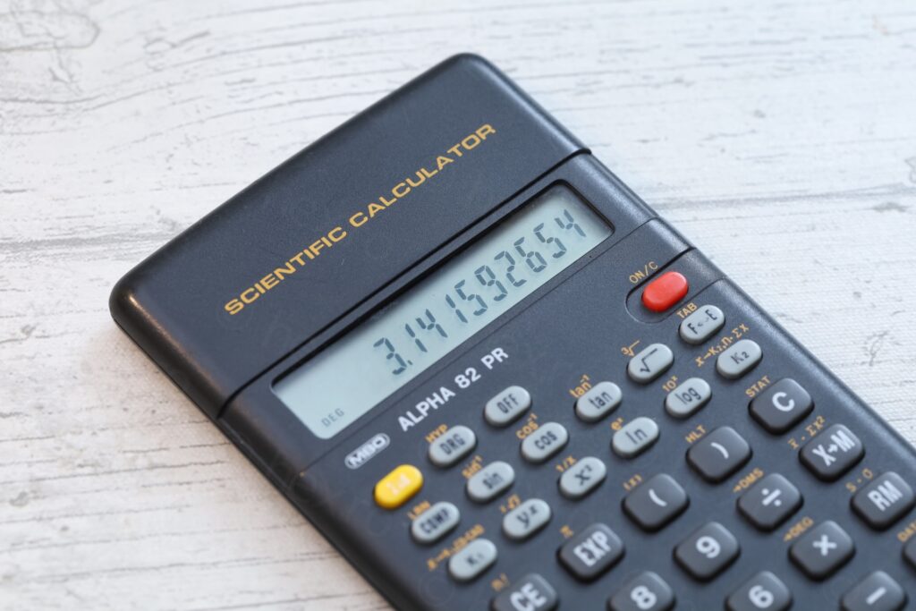
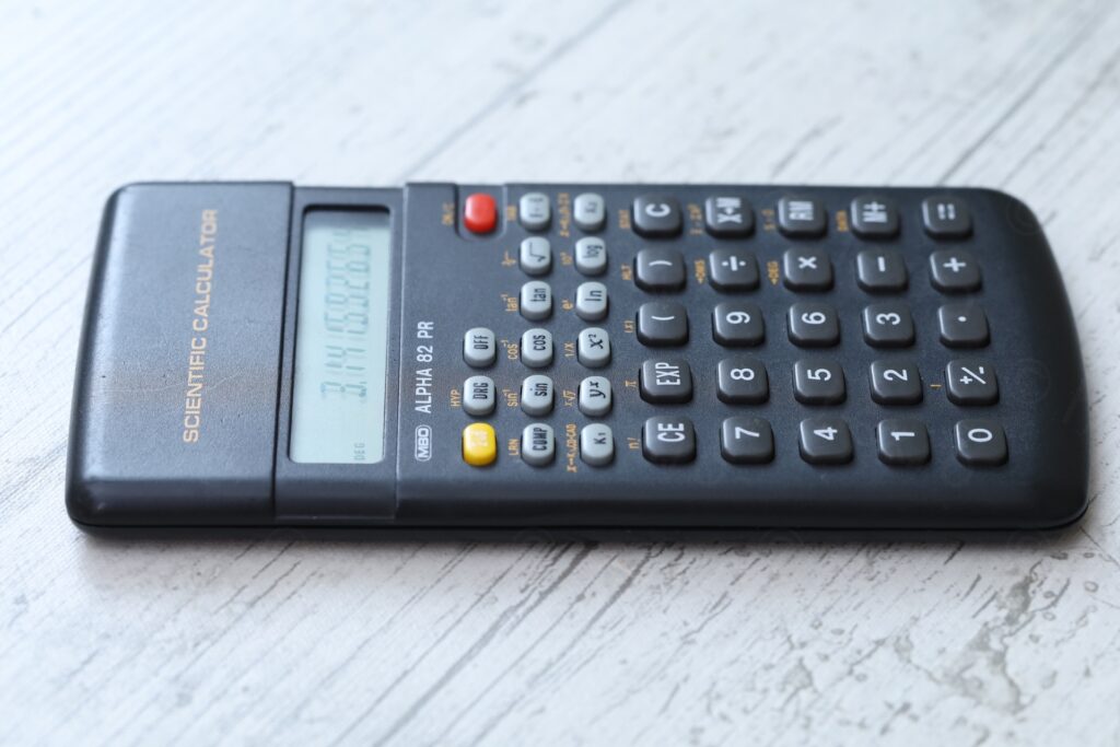
The “=” key is a bit faded.
As a small background story: I have an almost identical calculator and totally forgot about it for many years until I saw an identical one at a second hand shop! Bought the second one but forgot about it too until I found this one at a flea market. I bought it and figured I should start posting them so I don’t forget.
This one needed two new batteries and a bit of cleaning.
The calculator is branded “MBO Alpha 82 PR” and is build around the Sharp LI3301A CPU. Having a name, it helped me find the world of Sharp clones 🙂 Surprisingly, nobody scanned the manual so far – I hope I will, but that original calculator is far away from me for now.
But not all is lost. The Casio SRP-145N is based on the same CPU and its manual can be found online. It is more complex, but principles are the same.
Coming back to this calculator, It is interesting that it cannot calculate the yx values for negative numbers. For example, the combination 8 +/- yx 2 = (interpreted as 8, then followed by the +/- button press to make it -8, followed by yx button to rise to an arbitrary power, then followed by 2, to rise it to the power of two), produces error. This behavior is a “domain error”. Most likely, the calculator uses a combination of logarithm / exponential formulas to calculate arbitrary yx numbers, but logarithm is not defined for negative x. Typing 8 +/- x2 gives the right result since probably it just does a multiplication.
ON/C button is identical with C button. C button wakes it up from the Off state (just like the ON/C button). Pressing 2nd ON/C switches to STAT mode, just like 2nd C is supposed to do.
Programming the Scientific Calculator
I figured I should post a small program. One idea I had was to program it to calculate the power delivered by an amplifier into a 8Ω load, based on the Vpk captured on an oscilloscope.
Formula linking Vpk to Vrms is detailed on RF Cafe website here: https://www.rfcafe.com/references/electrical/sinewave-voltage-conversion.htm. Assumptions are that the signal is a perfect sine wave and that the load is purely resistive, without parasitic inductance. As a clarification, the meaningful value is Vpk and not Vpk-pk.
Power = Vrms2 / R = Vpk2 / (2R)
K1 and K2 memory locations are useful for constants because pushing their respective button also triggers a multiplication with their memory value.
Thus, let’s store the load resistance at K1 memory location, this way we can switch between 4Ω, 8Ω or 12Ω load easily without changing the program.
| Button presses | Meaning |
| 8 2nd K1 | Store 8 at location K1 |
| 2nd COMP | Switch to Learning mode (LRN is displayed) |
| 2nd ( | Program will ask an input value – ((x) is displayed) |
| x2 | Program will rise the last value to power of two |
| / ( 2 K1 ) = | Divide Open left parenthesis 2 K1 – this also does multiplication, so it will multiply 2 with the K1 memory value Close left parenthesis Equals |
| 2nd COMP | Exit learning mode |
Running the program is triggered by the COMP button. To confirm that you finished typing the input value, you have to press COMP again. Thus, to run the program with a Vpk = 1.414V you have to:
COMP 1.414 COMP
Value displayed is: 0.12496225 which is very close to the theoretical value of 0.125W of power that a 1Vrms = 1.414Vpk signal produces into an 8Ω load.
To switch to a 4Ω load is easy: 4 2nd K1. Then program can be ran again, and will produce: 0.2499245. It is faster in fact to just multiply the previous value with two (less buttons to press). But I hope it highlights the usefulness of K type memory locations.


Agnieszka
Posiadam taki kalkulator. Używałam go w szkole średniej do obliczeń geodezyjnych. Niestety nie korzystałam z możliwości programowania. Wystarczyły mi funkcje geometryczne i 4 chyba aż pamięci. posiadam oryginalne opakowanie wraz z instrukcją. w razie czego mogę ją zeskanować i udostępnić