


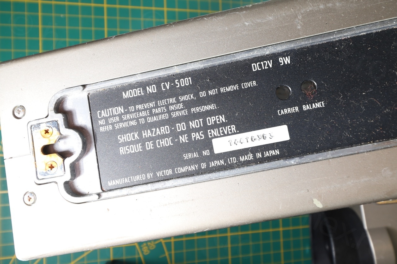
I found this mini CRT inside a JVC-CV5001 camera that I have bought at a flea market.
Compared to other cameras that I take apart, this camera was huge and with no compartment for tape – sure sign that it was old. It looked like it had a mini CRT inside the view finder, so I was curious to buy it.
Camera overview
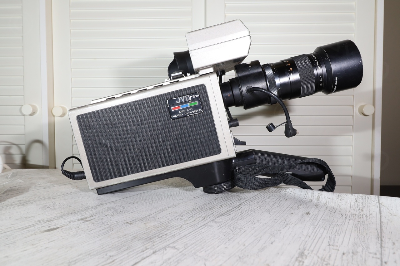

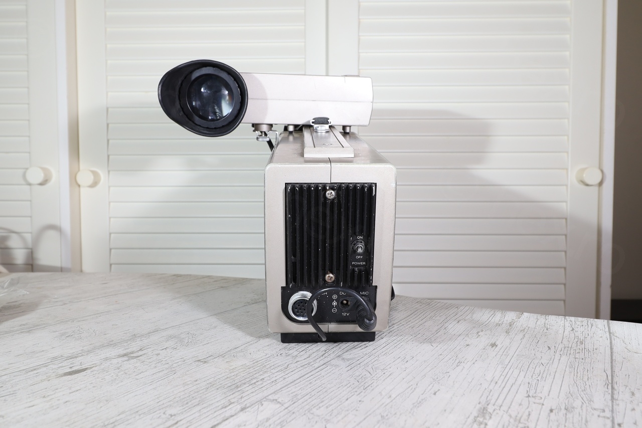
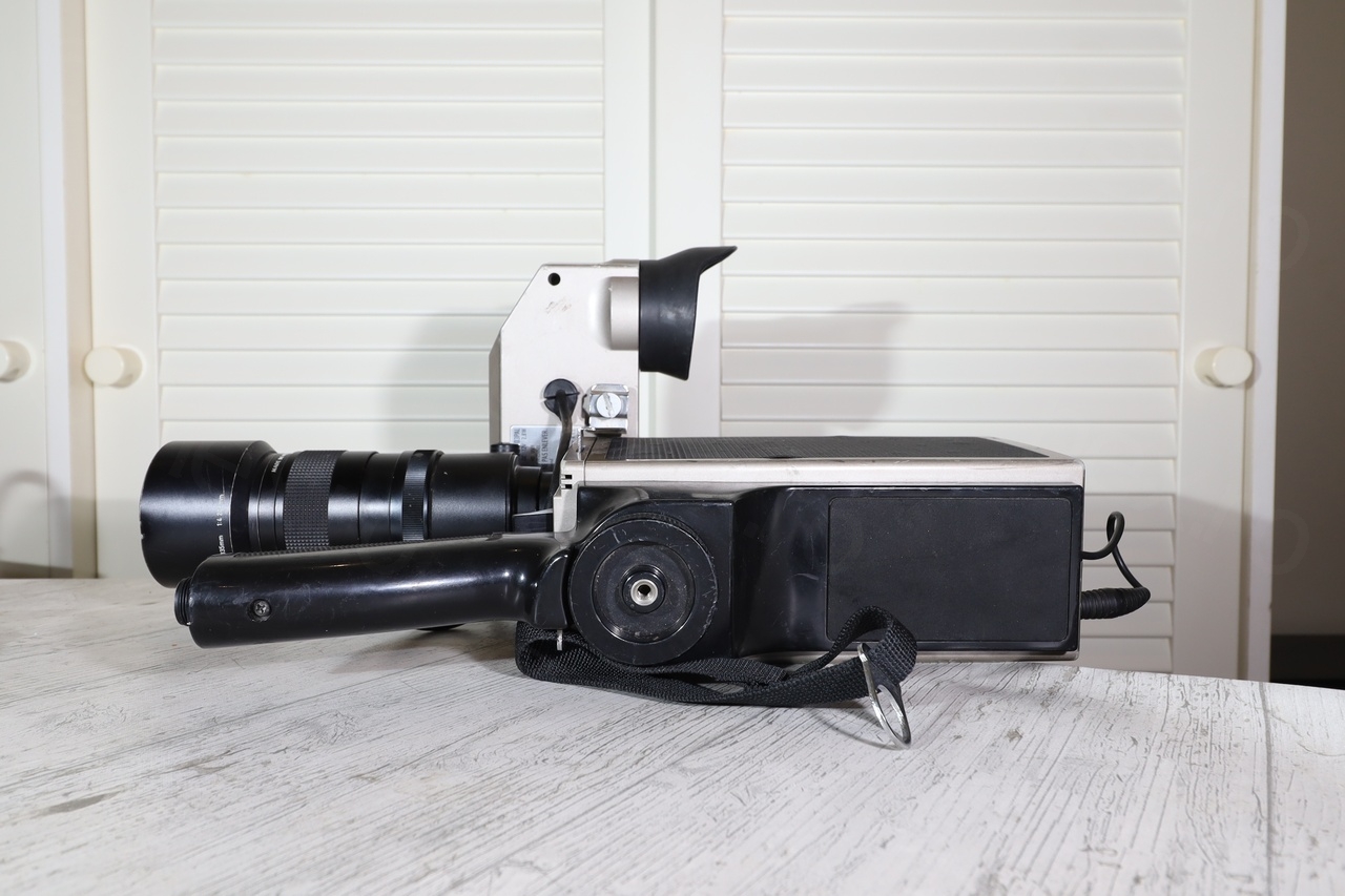
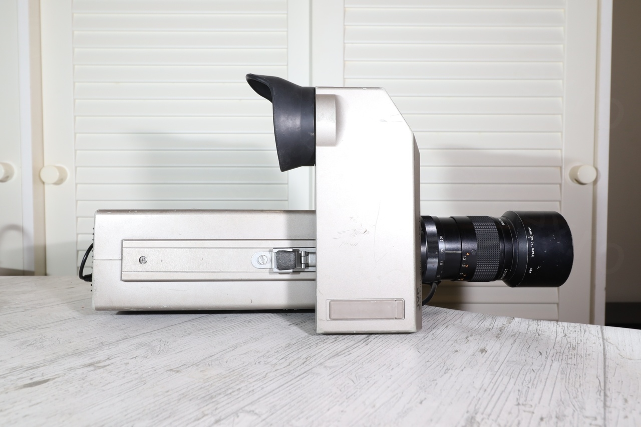
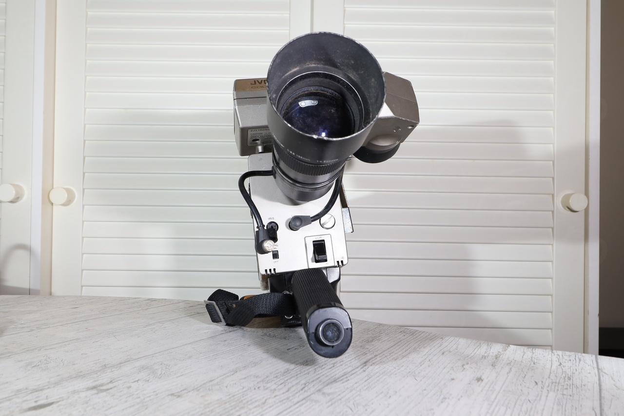
The viewfinder was a large block on top of the camera:
I have already searched to see if there’s a schematic online, but I was not able to find anything. The challenge was now figuring it out on my own, thus, what better place to start than dismantling both the camera as well as the EVF unit, in hope of finding clues how to power on the little CRT.
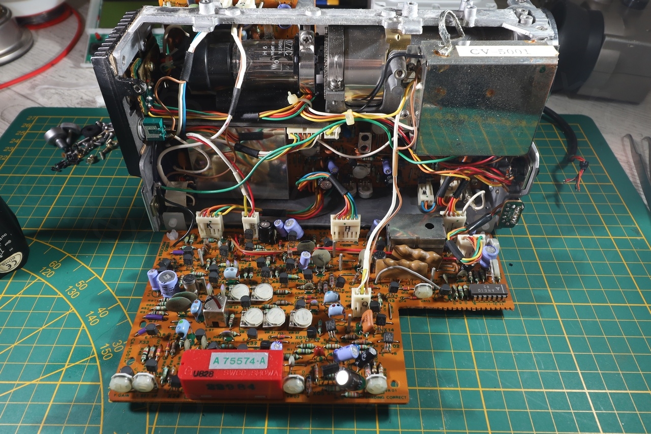
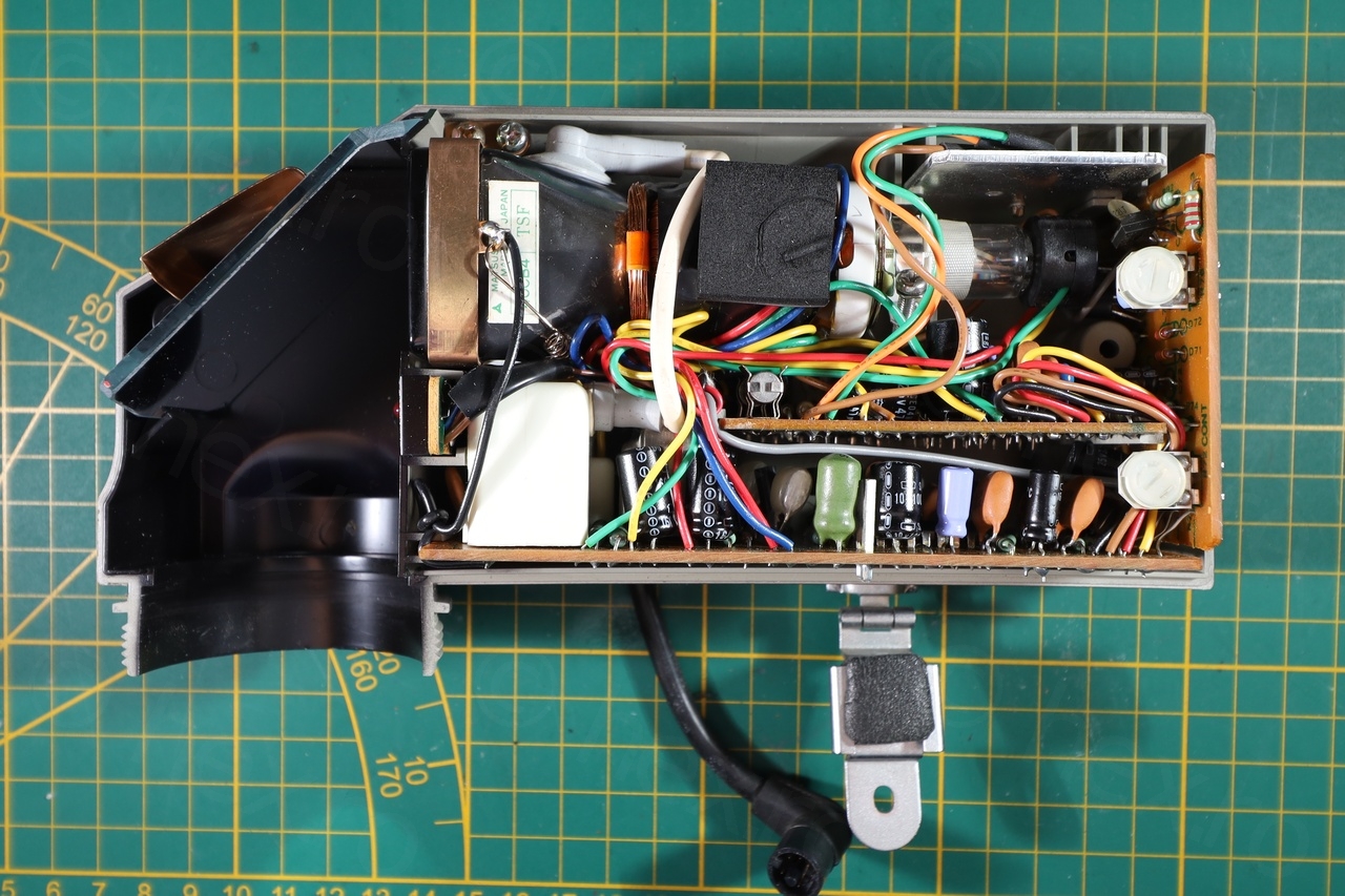


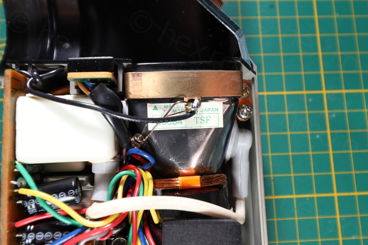
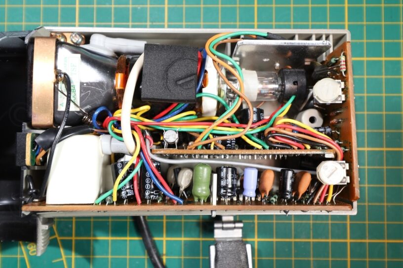
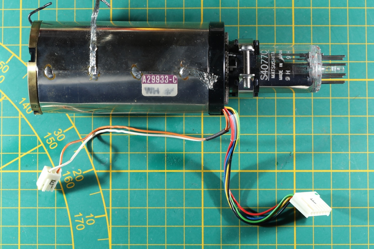
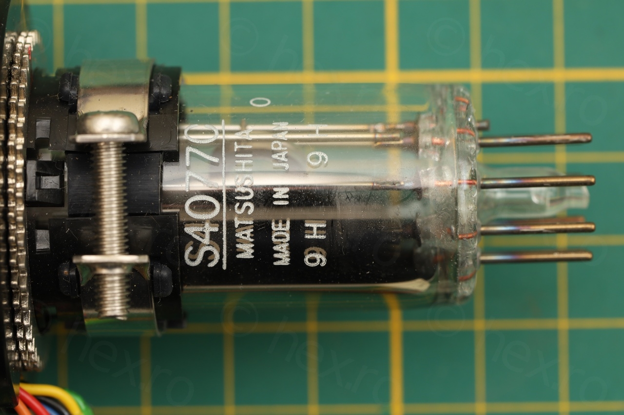
The CRT is a Matsushita 40CB4, which is one of the “largest” mini CRT I have encountered.
VCC, GND and Video IN signals
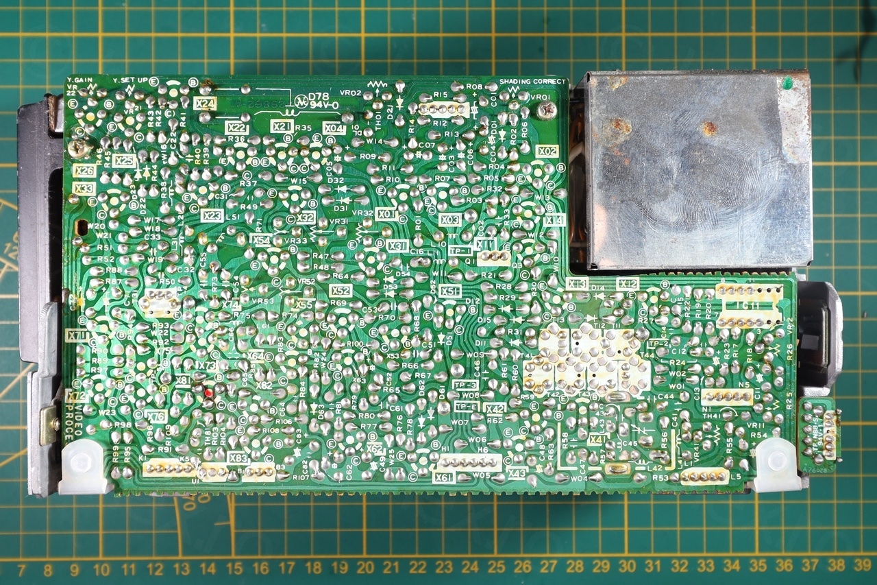
Without schematic, the challenge is to locate the input pins that power to the CRT as well as finding the one that carries the Video IN signal.
There are usually two ways to identify the signal pins in more modern view finders – either the case of the Fly Back Transformer is connected to GND or, starting from the driver IC, trace back the VCC / GND / Video IN provided that you have a schematic for the driver IC.
The FBT had plastic outside and many pins. Not helpful. The on-board driver IC is an AN294 but was not able to find any schematics on it. Again, dead end.
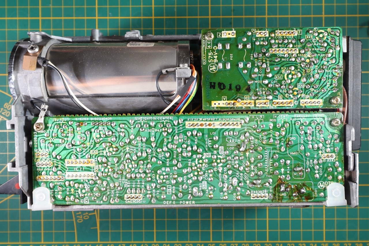
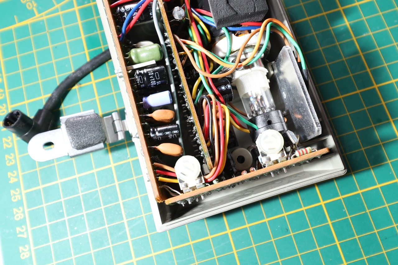
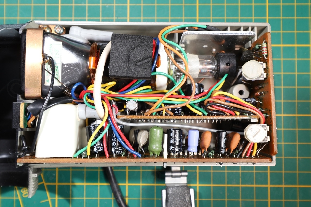
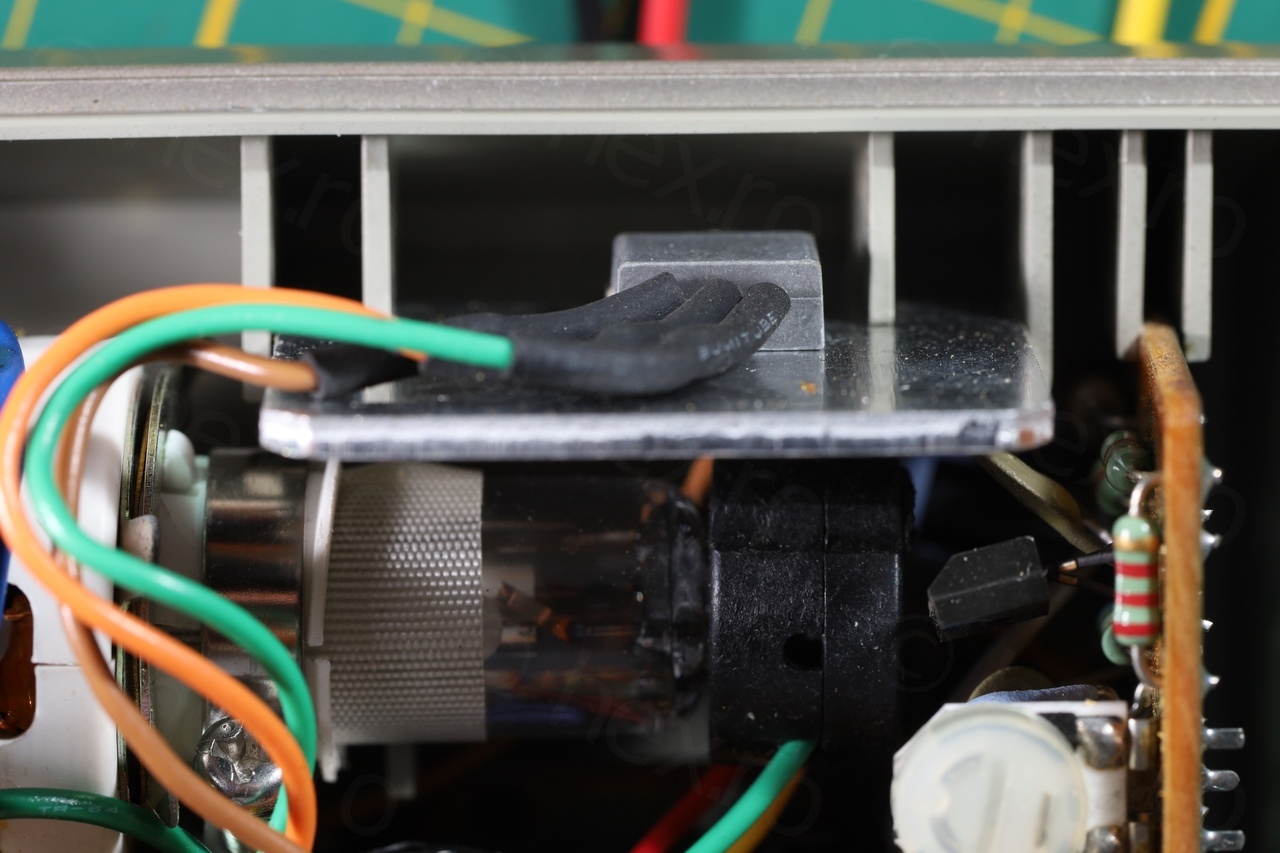
Looking closer at the build, I spotted a component looking like transistor / voltage regulator, mounted on a large heat-sink:
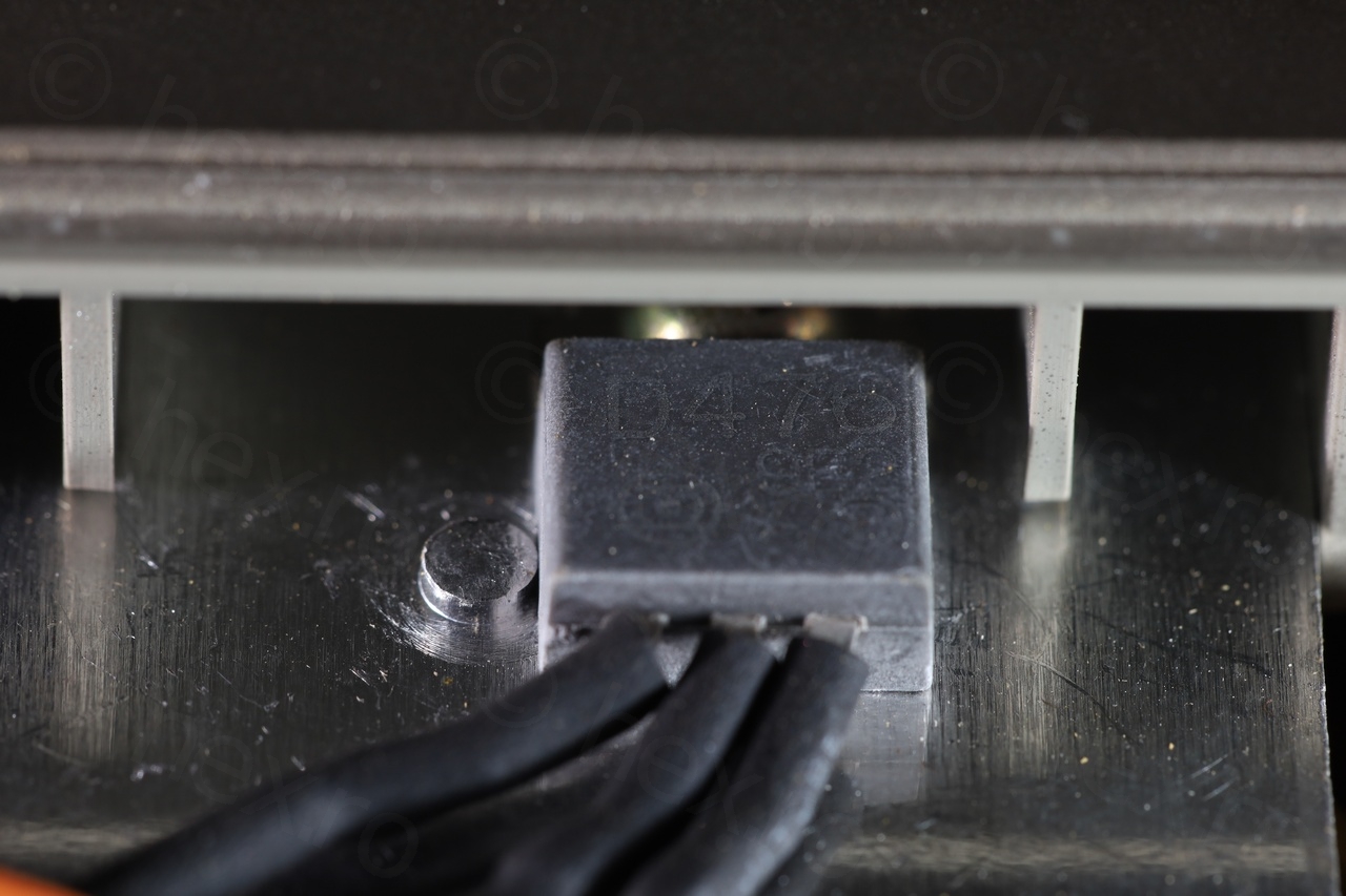
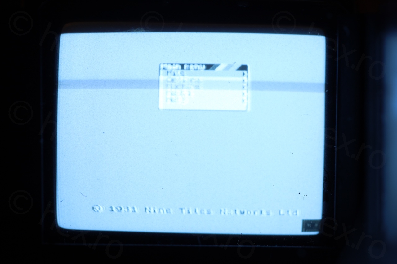
Schematics for D476 are available, it is a transistor meant for switching power supplies. I was thus able to identify the GND signal and VCC using the conductivity mode on the meter between the transistor pins and the input ones. With the CRT powering on, I tried the remaining pins in search of the one that was accepting Video IN. Finally, an image appeared on the screen:
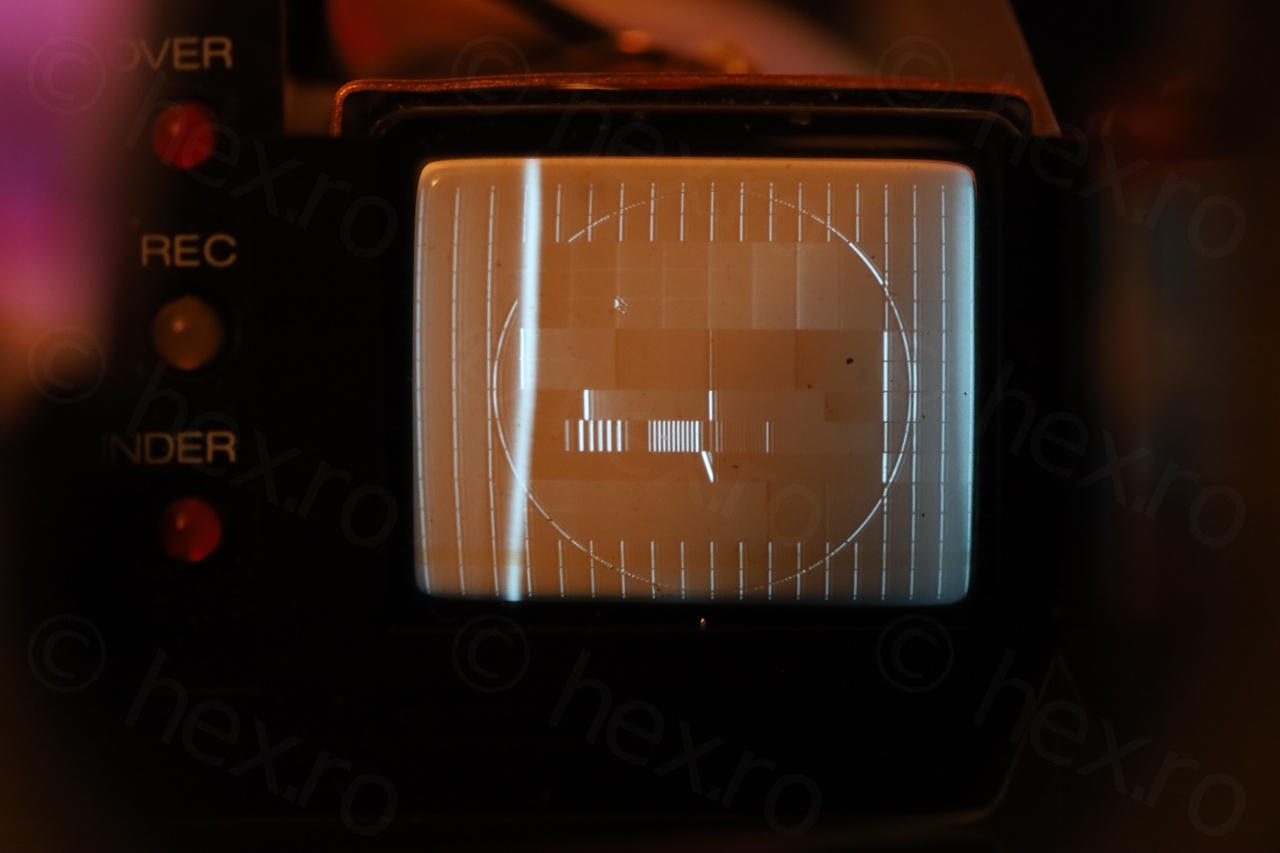
The image looked inverted and having a big vertical white line towards the left. I had an urge to swap all capacitors, but this EVF was so old, I preferred not to touch anything and conserve it as is. But it kept bothering me, and kept coming back to the desk to have a look again. Something still didn’t feel right.
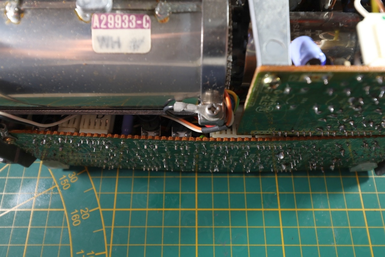
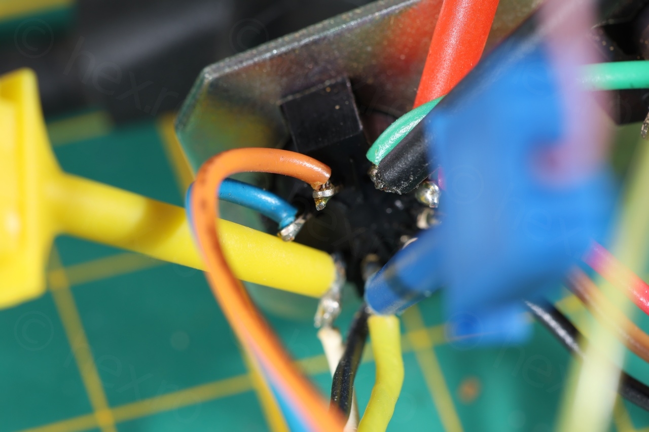
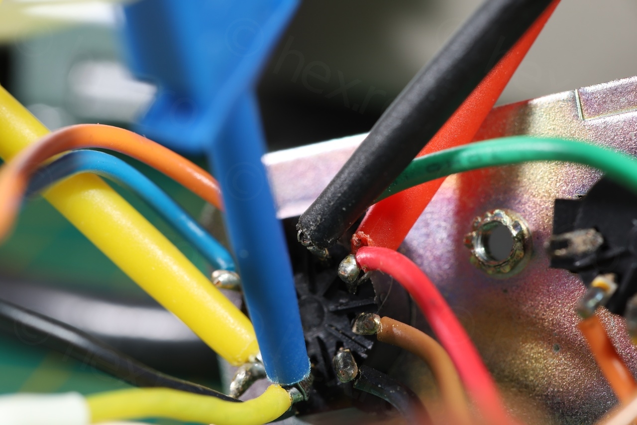
Breakthrough arrived through an unexpected glimpse, the cluster of cables that were going towards the EVF female plug drew my attention:
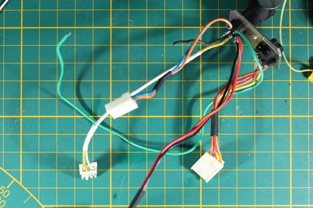
When doing the trial and error, I was using directly the EVF plug to provide the signals. VCC and GND were identified, and found the one where, when given a composite video signal, the image would appear in CRT:
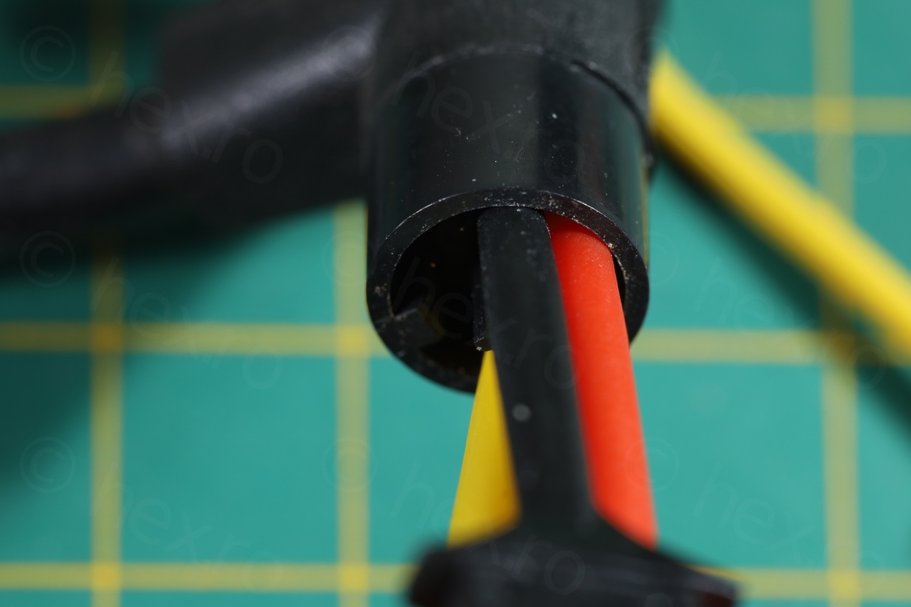
However, when looking previous White / Yellow pair from the female counterpart of the plug, the pin I found sensitive to Video IN was in fact connected to the fatter cable (Yellow). This seemed paradoxical. Fatter cable from a pair means that one may be the GND and expecting it to be darker in color – but it was Yellow as Video IN plugs are. Faced with this paradox, I decided to swap the Video IN signal, provide Video IN to the thin white cable, and connect the GND to the yellow cable.
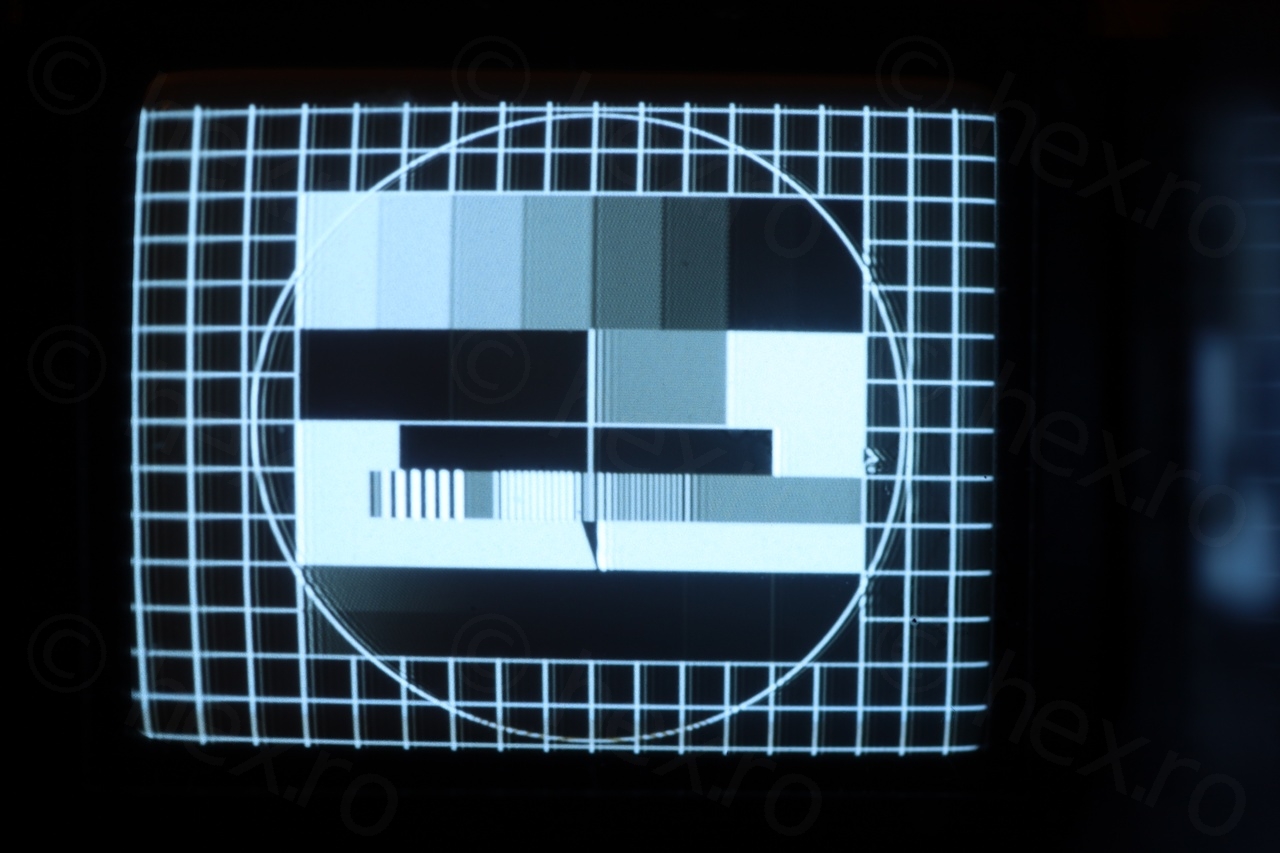
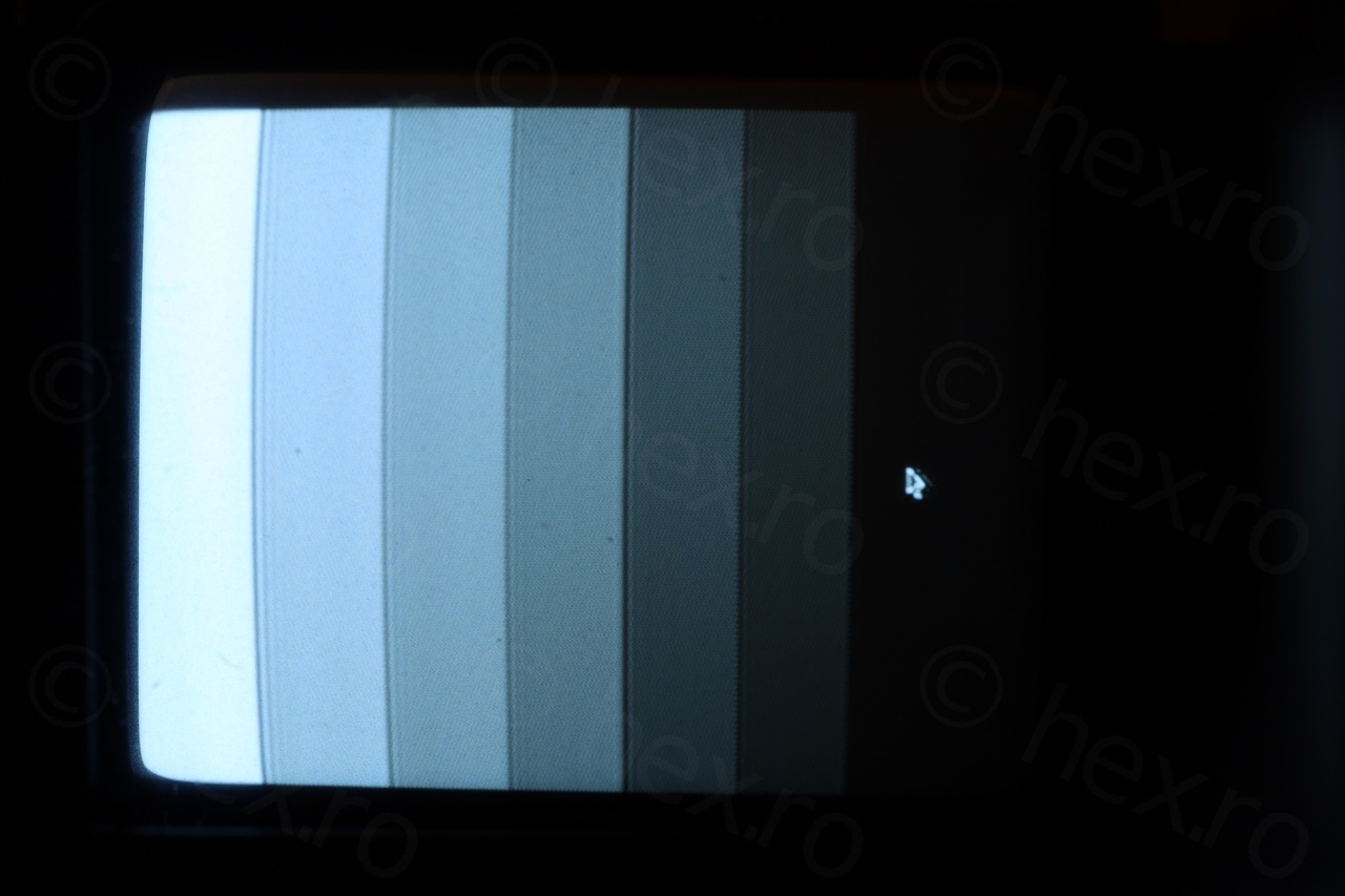
Et voila:
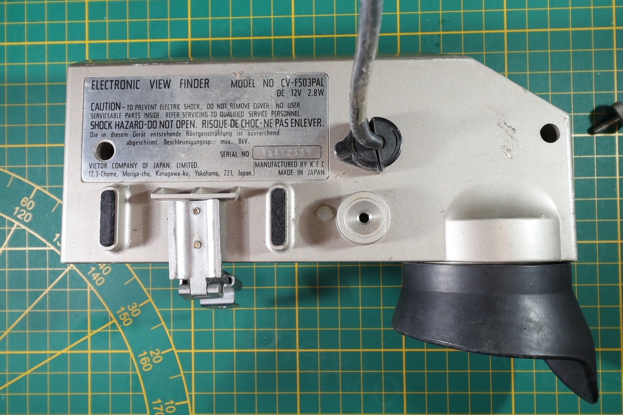
Connections
Looking towards the EVF plug, here are the signal PINs for the JVC CV-F503PAL EVF unit:
Conclusions
There is still some ‘ringing’ (not sure how to call the effect): image appears to be doubled (or repeated) few times, fainter and fainter to the right. Text is hard to read and the image to look a little blurry. I guess replacing the capacitors would fix this now (or improve it a lot) but I am not willing to touch such an old board.
Special mention
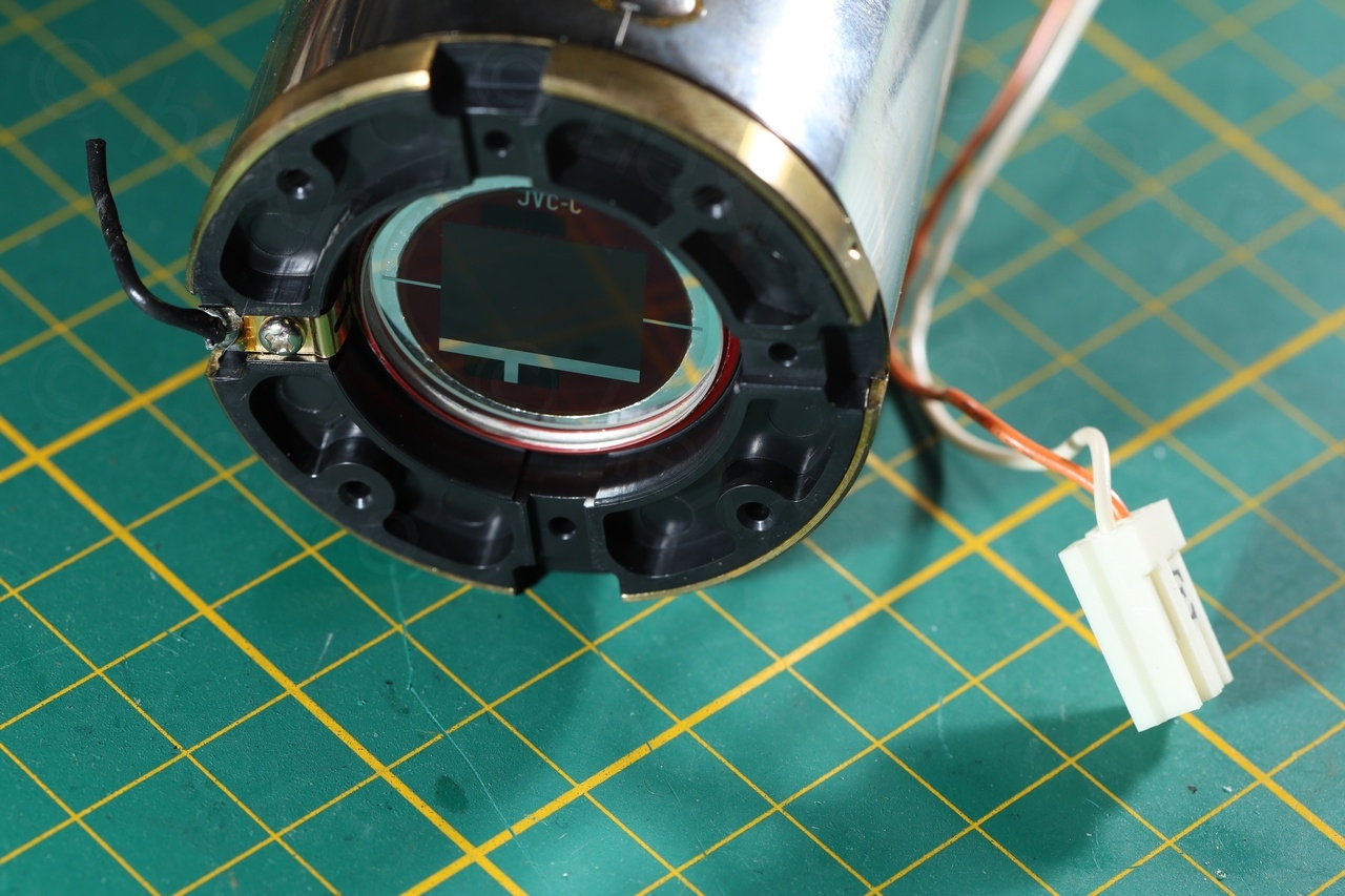
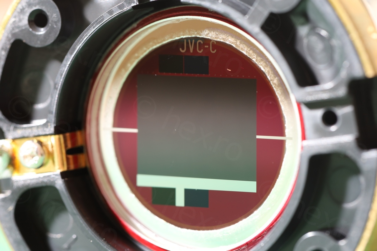
A special mention for the image sensor below. I decided to conserve it too, although I will probably not be able to power it on as it too requires a high voltage source.


Leave a Reply