


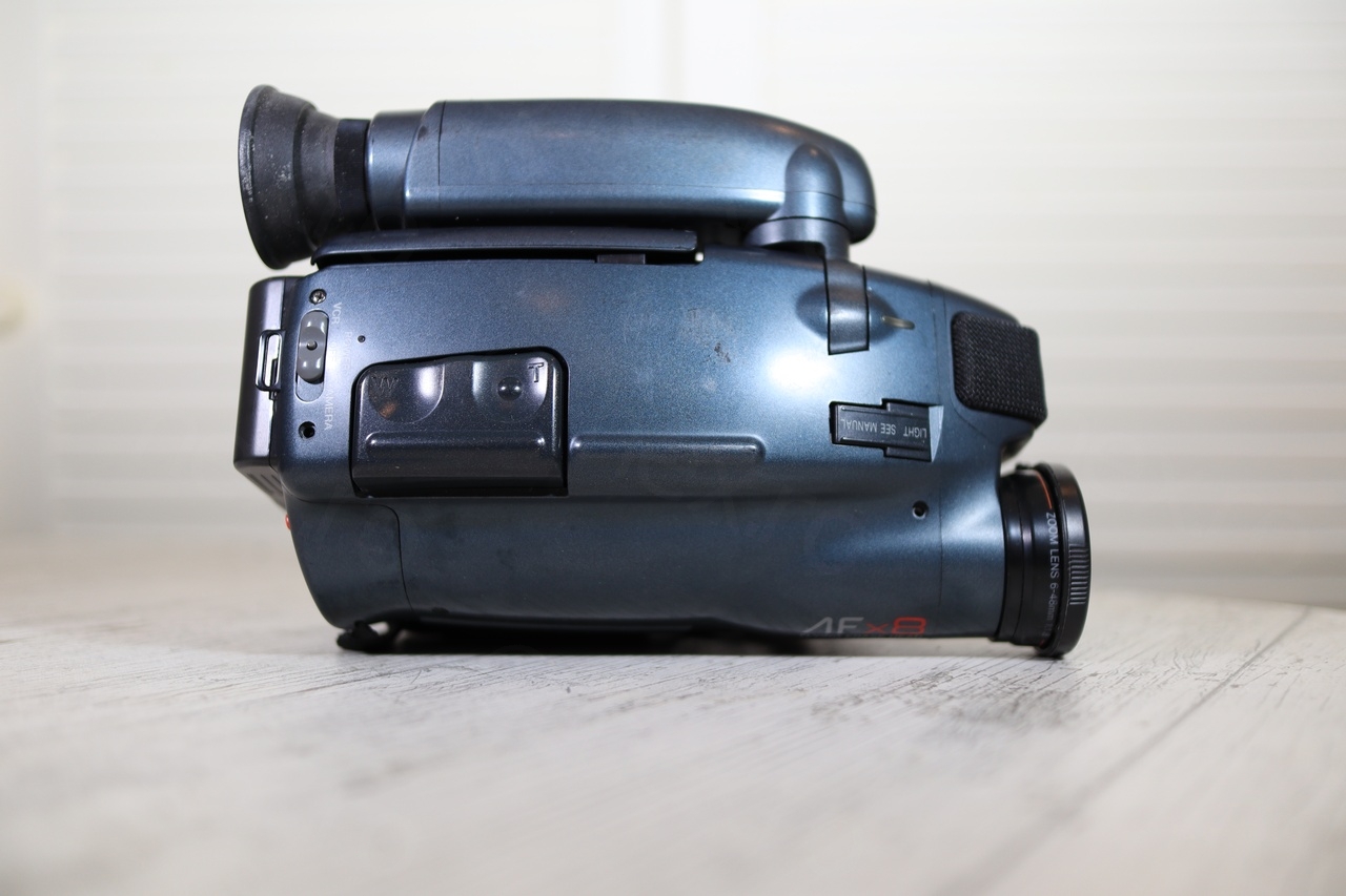
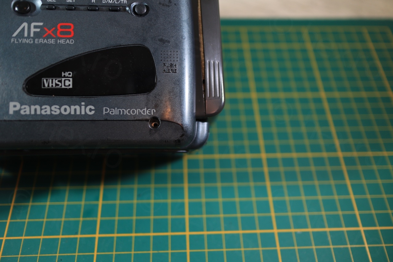
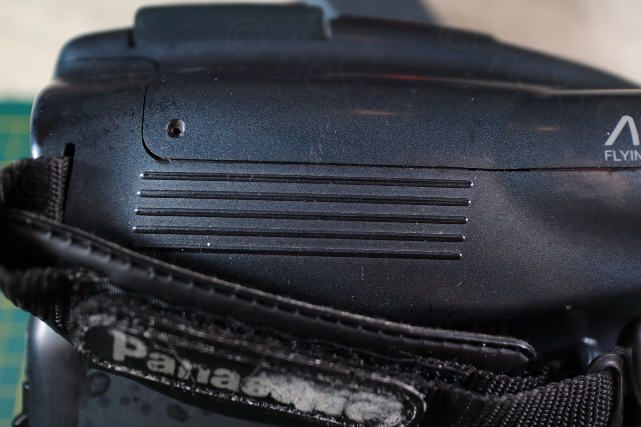
I like to walk through garage sales / flea markets and if the price is right for some old camera that looks like it has a mini CRT, I end up buying it. Same happened with this Panasonic AFx8 Palmcorder.
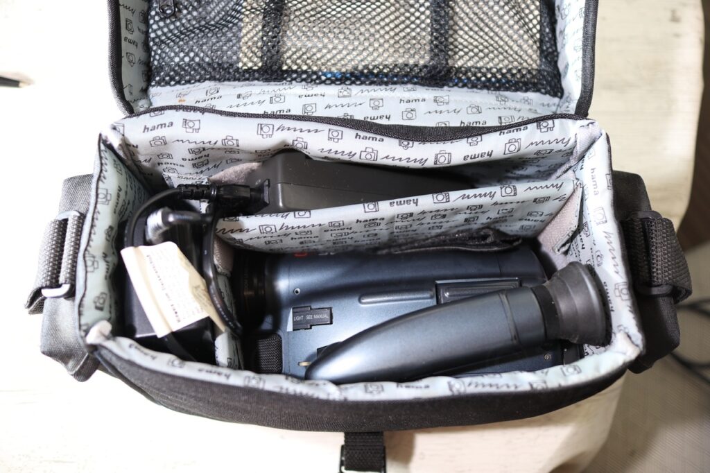
Camera Bag
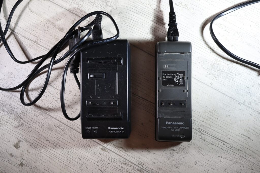
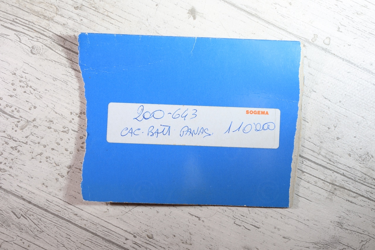
The Panasonic was sold in a nice Hama carry bag. Besides the camera and its charger, inside I found the name tag of the owner (a person from Italy), a Vatican medallion and a little hand written note with the price of the charger in Italian Lira:


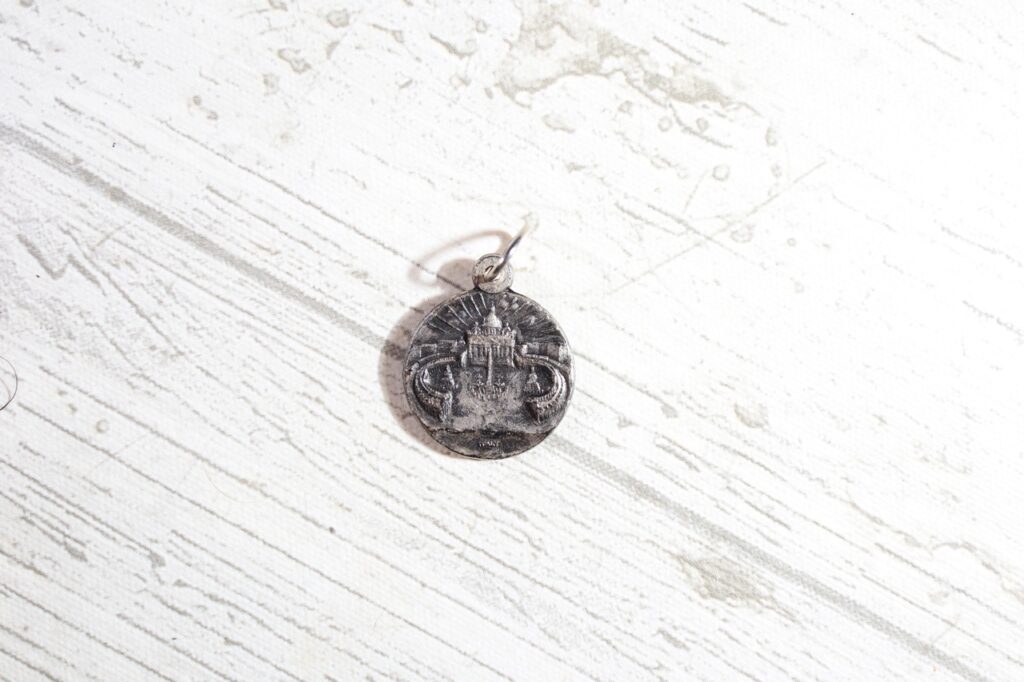
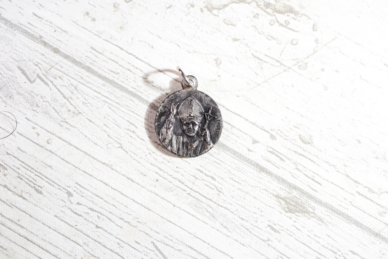
Vatican Medallion 
Vatican Medallion


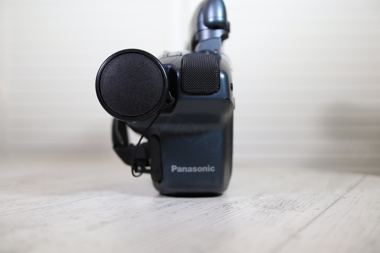
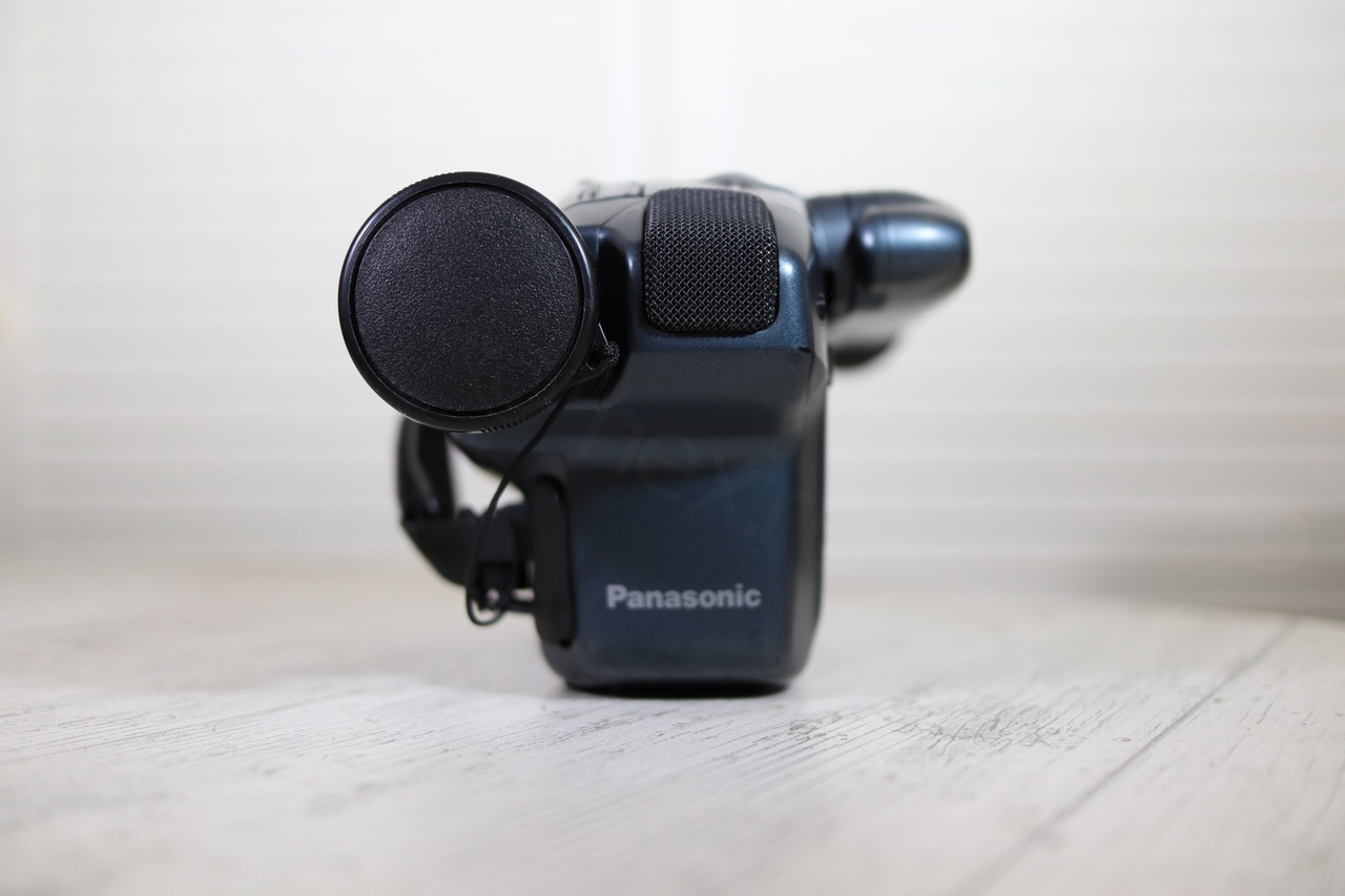
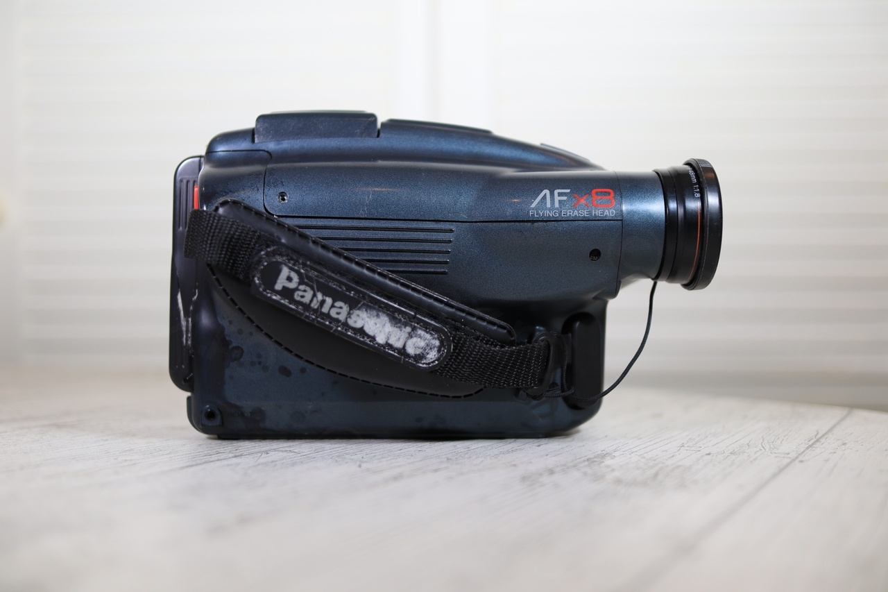
Camera Overview
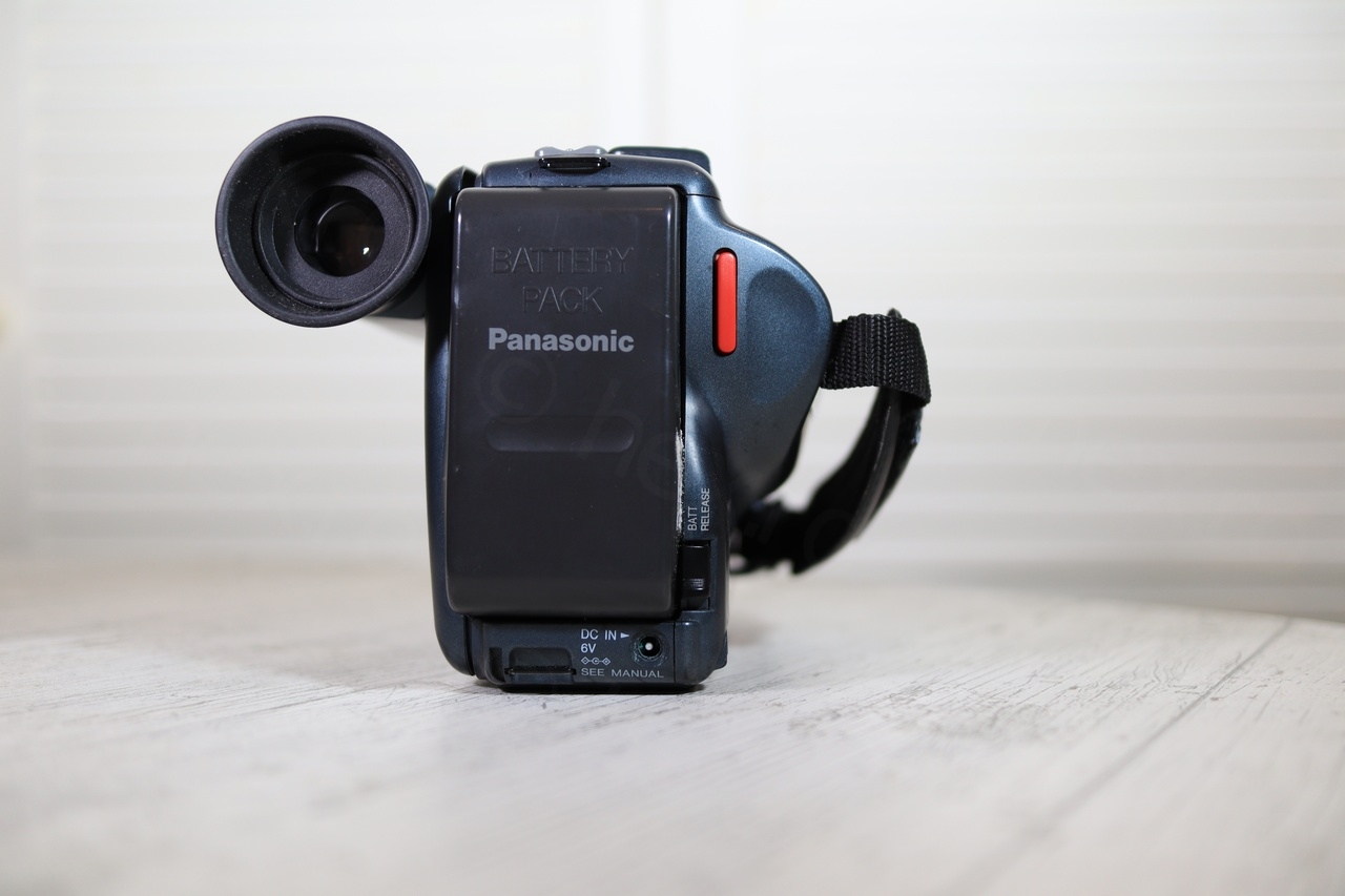
The camera itself was in a sorry state. Some screws were missing and it handling it gave off a ‘squishy’ feeling, not to mention that the battery was swollen:

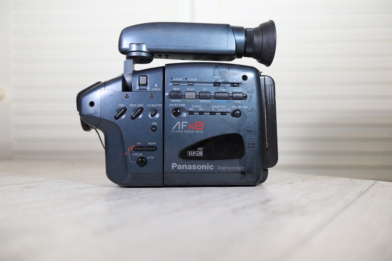
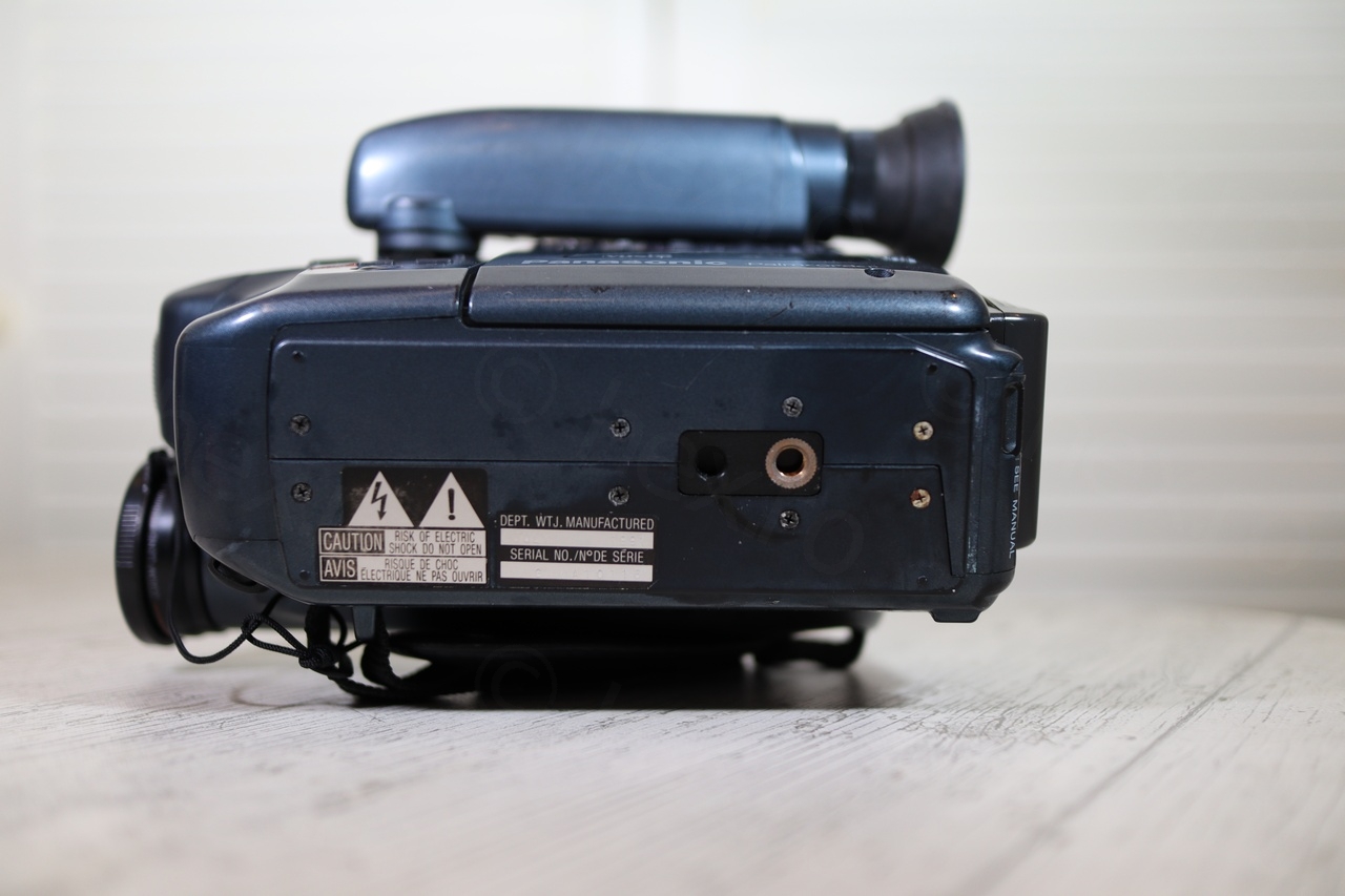

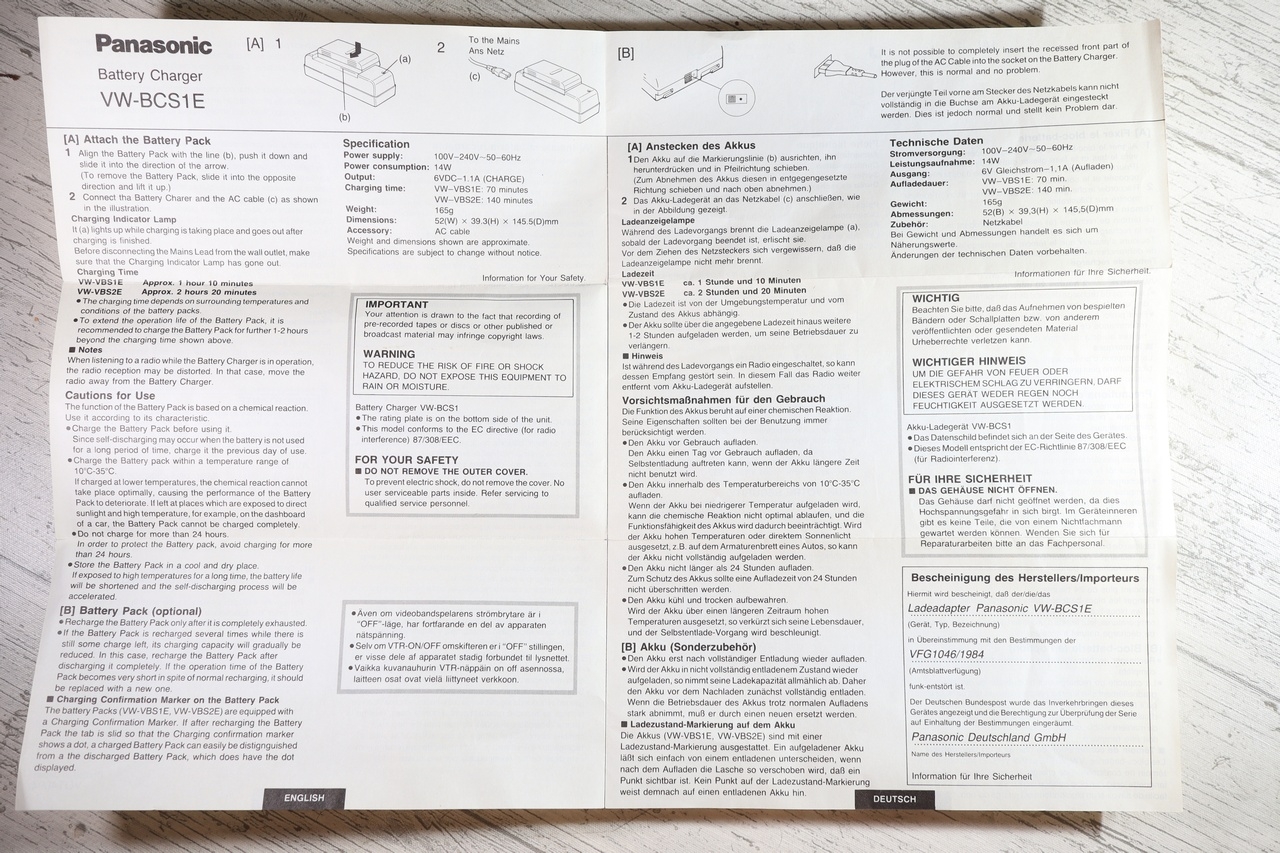
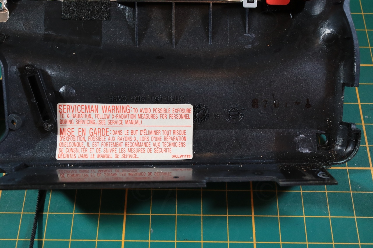
As you can see from one of the photos above, camera was made in July 1991.


Opening up
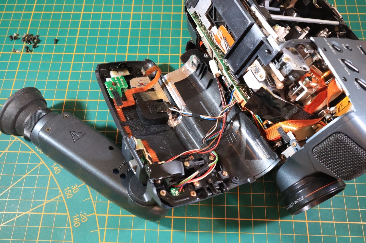
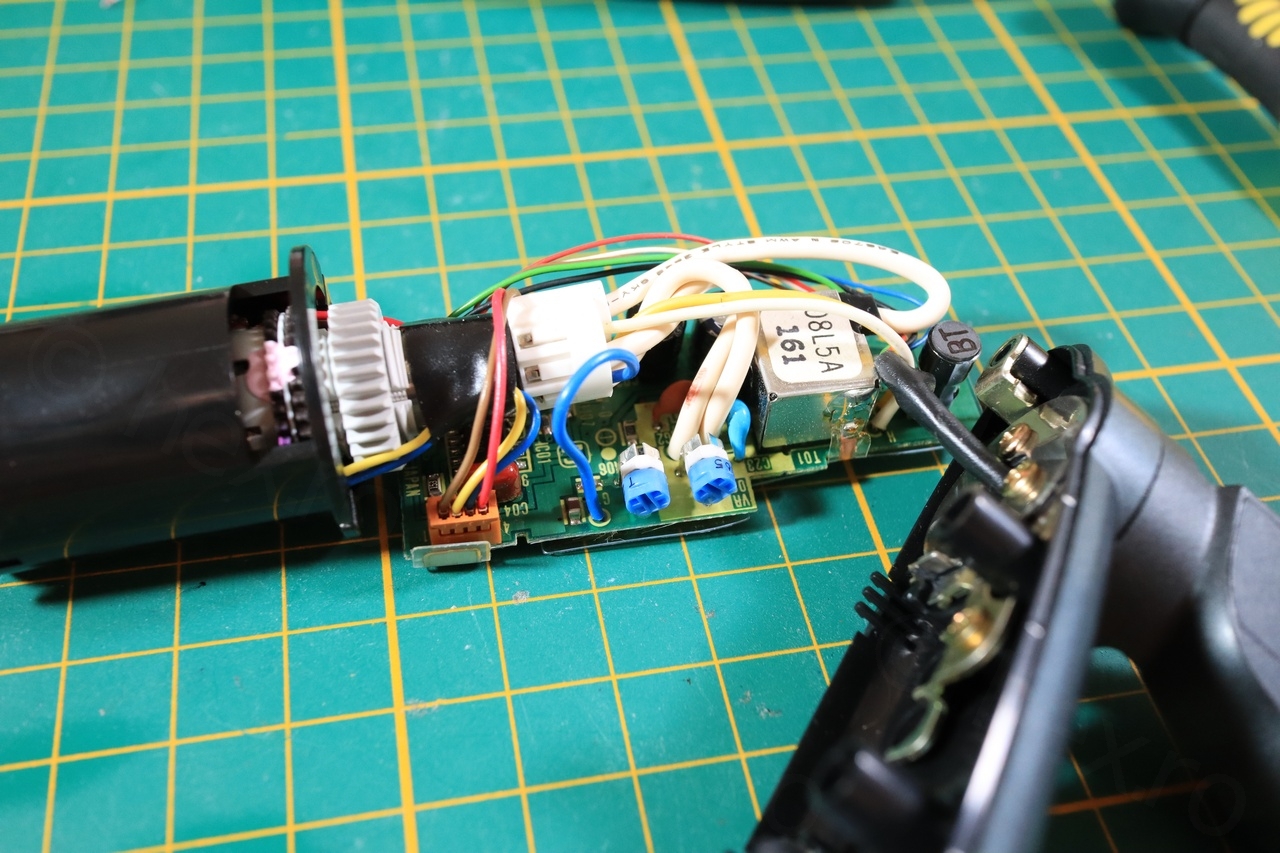
Opening the camera was easy (less screws to take out!) and getting to the EVF unit was quick. Decided to proceed with the complete dismantling, curious to see if there were any bodges inside, or some quartz crystals that I could salvage.
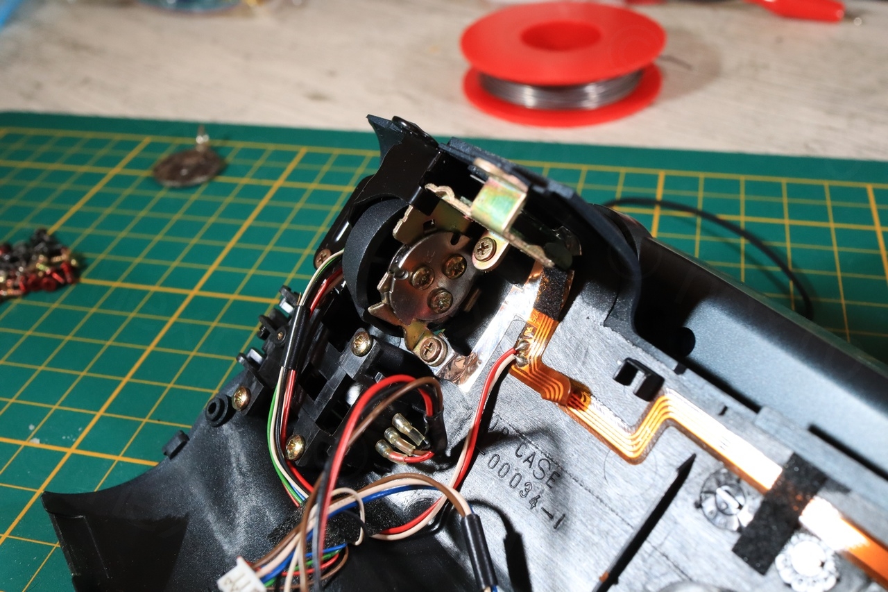
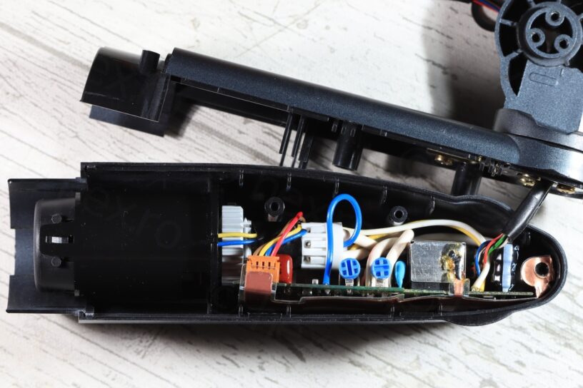
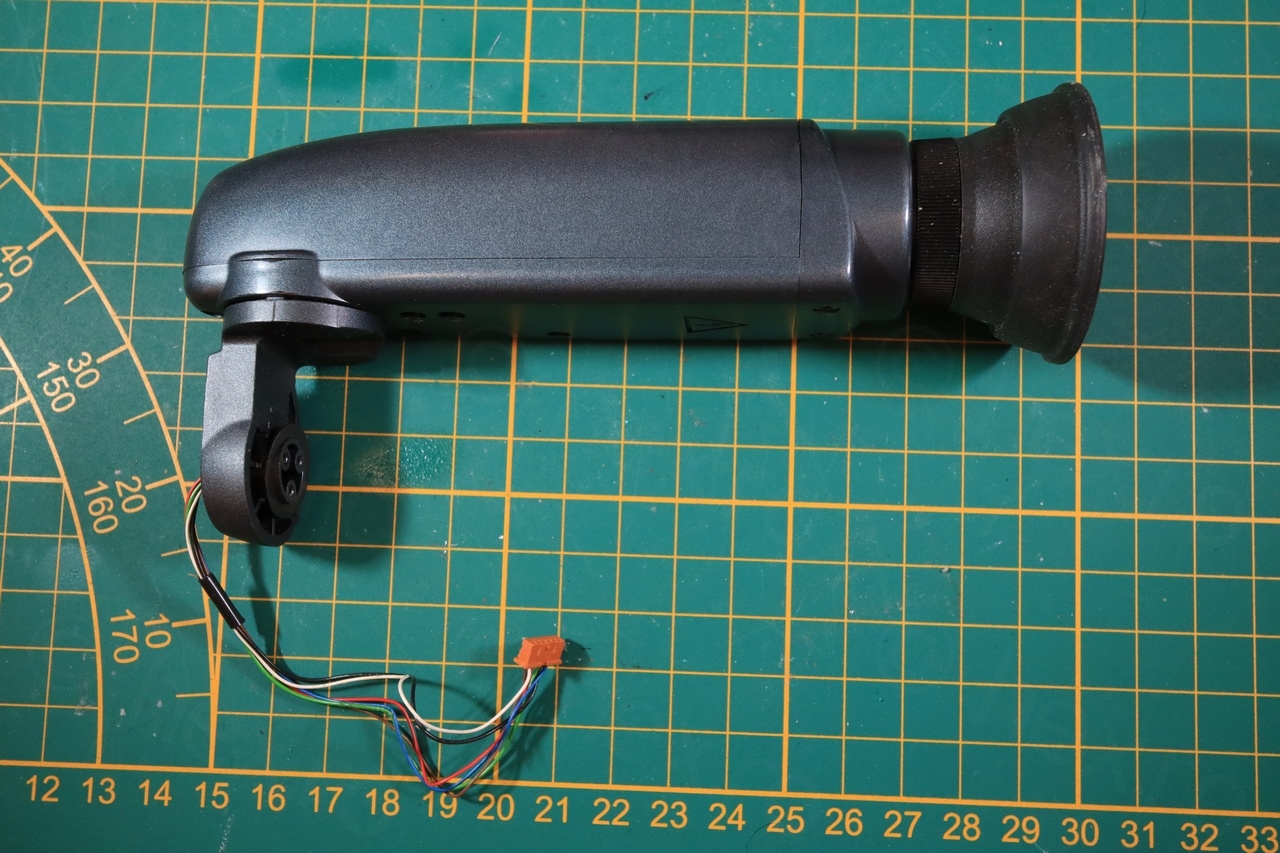
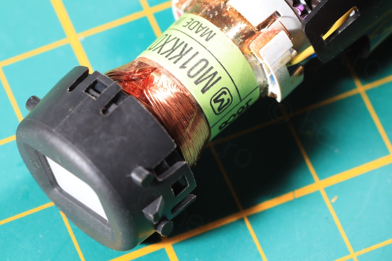
EVF Unit
Getting to the EVF unit was easy, but opening it up was hard. It seemed that it will snap, but with enough persistence squeezing the sides I was able to create a gap wide enough for the prying tool.
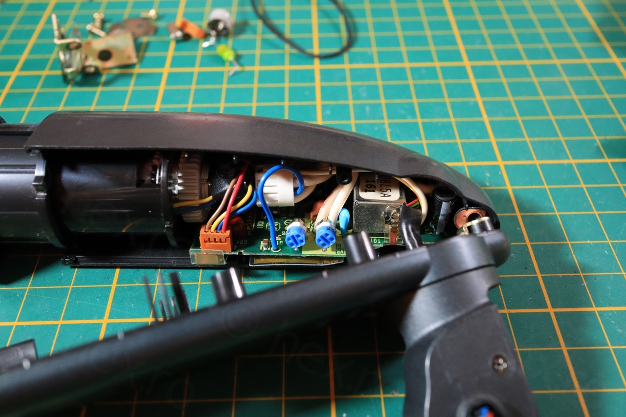
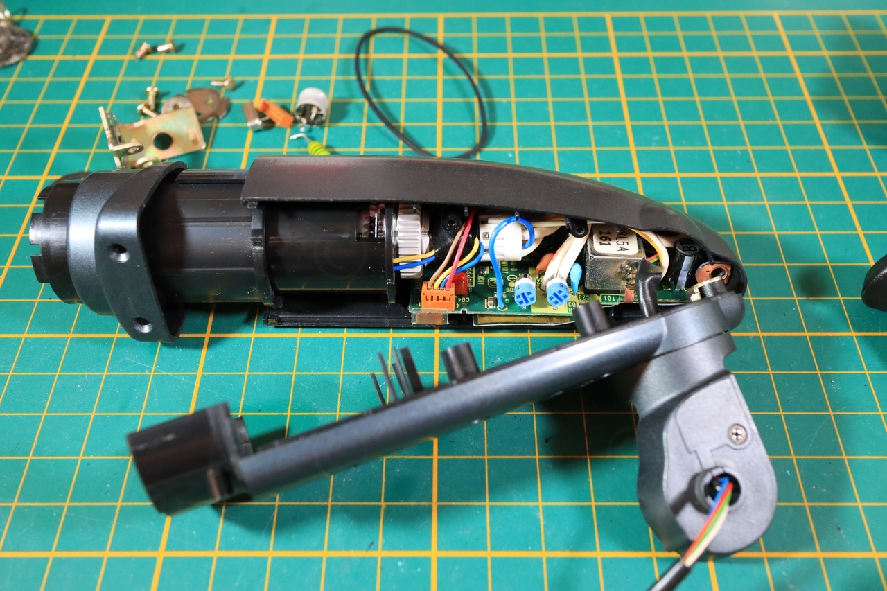
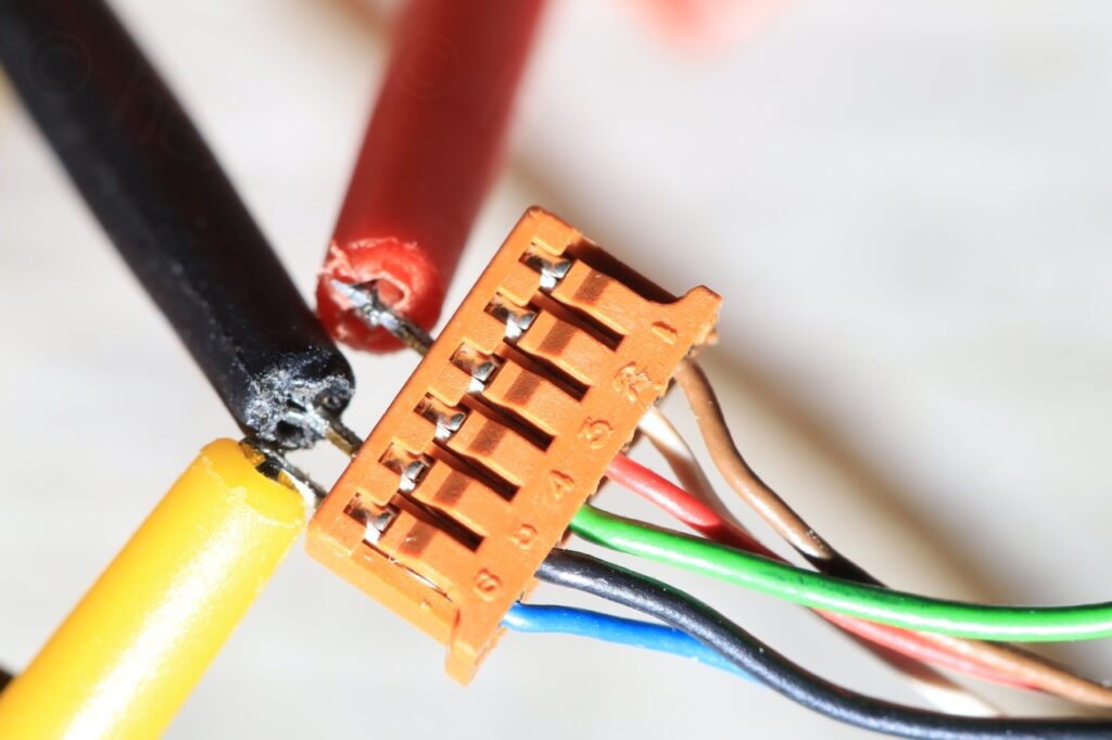
Identifying the input signals was easy, VCC is the red wire, GND is the black wire, and Video IN is the blue wire:
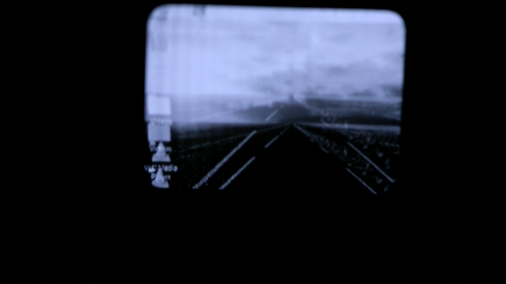
However, results were disappointing 🙁 I was able to get it to display the image, but the image was jumpy. I recorded both a video (below) to see the jumpiness as well as taking a photo (which shows the two images over-imposed) but the photo shows an additional defect, some vertical lines appear to the left side of the CRT:
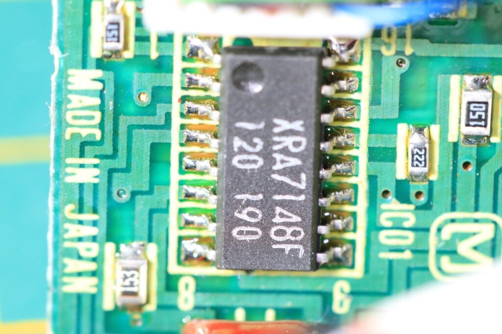
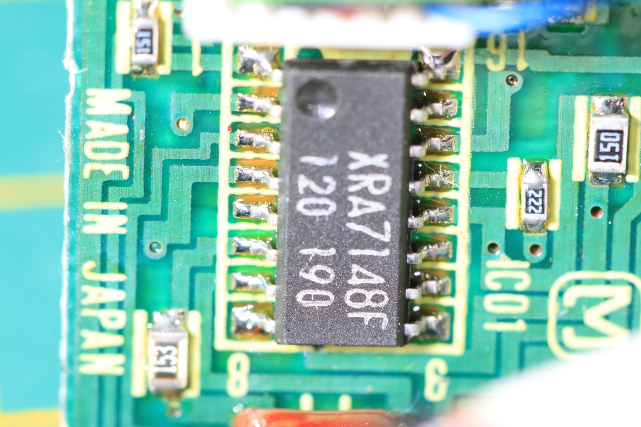
I had to inspect the driver board. The core was an XRA7148F chip (which I assume it is the same with BA7148F) and three electrolytic capacitors.
XRA7148F 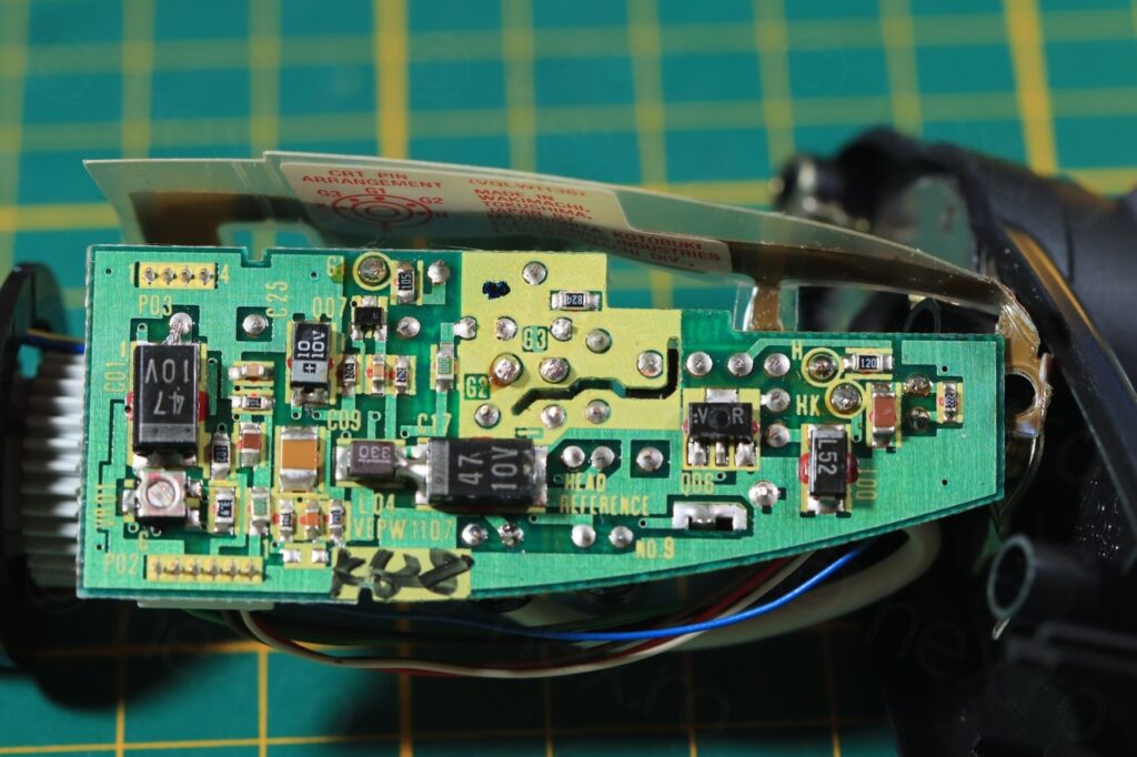
Board overview 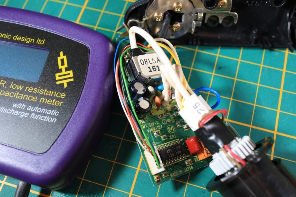
Locating the 3 caps. 
De-soldered joints 
Cleaned up


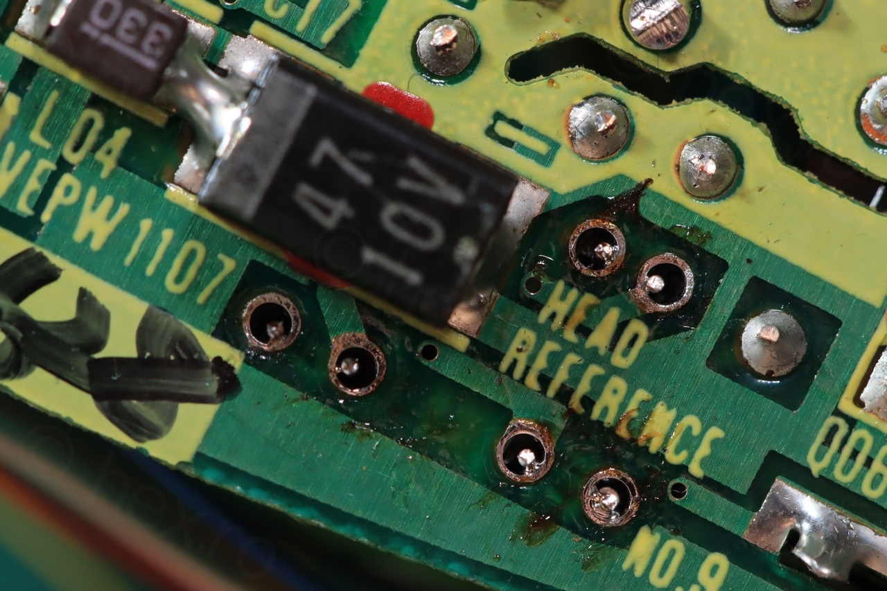

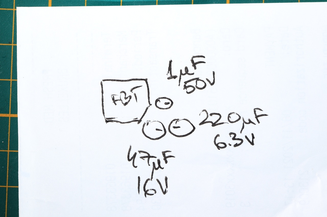
Decided to de-solder them all to measure out of circuit, as one was already measuring badly in circuit (the 1uF@50V one). Same story out of circuit. Given they were > 30 years of age, I figured I should swap them all if now I have them all out, so I proceed to take a not of their layout and ordered some spares:
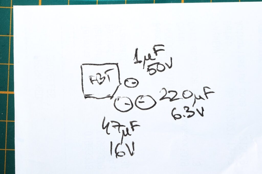
Capacitors layout 
New capacitors 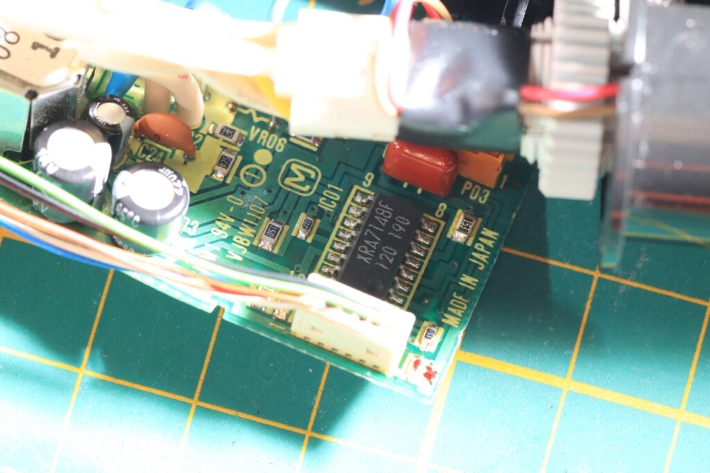
Board re-capped

Replacing was easy, and there was an improvement! No more vertical lines on the left hand side. However, the image was still jumpy …
Trying to debug was difficult because I see no schematic of the XRA7148F. The closest datasheet I can find is the one for BA7149F, which states that “The differences between the BA7149F and the BA7148F are the horizontal blanking, horizontal AFC output, HD output phase and pulse width.“
The example application schematic for the BA7149F (suggested by the producer) shows a 15kΩ resistor on pin 6 and a 100nF on pin 7 for the Vertical Oscillator block:
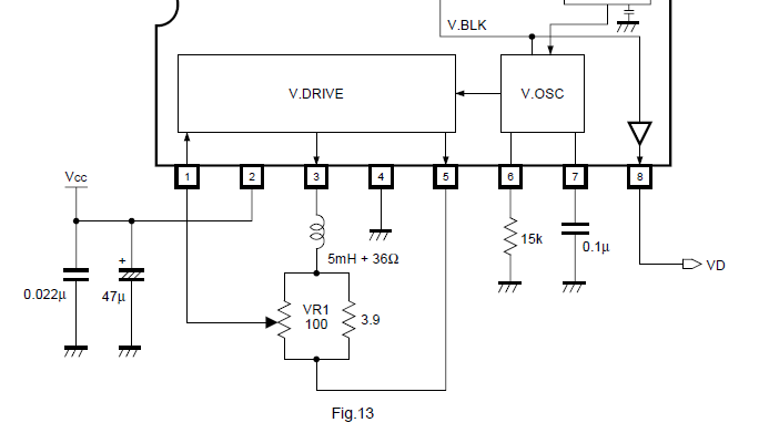
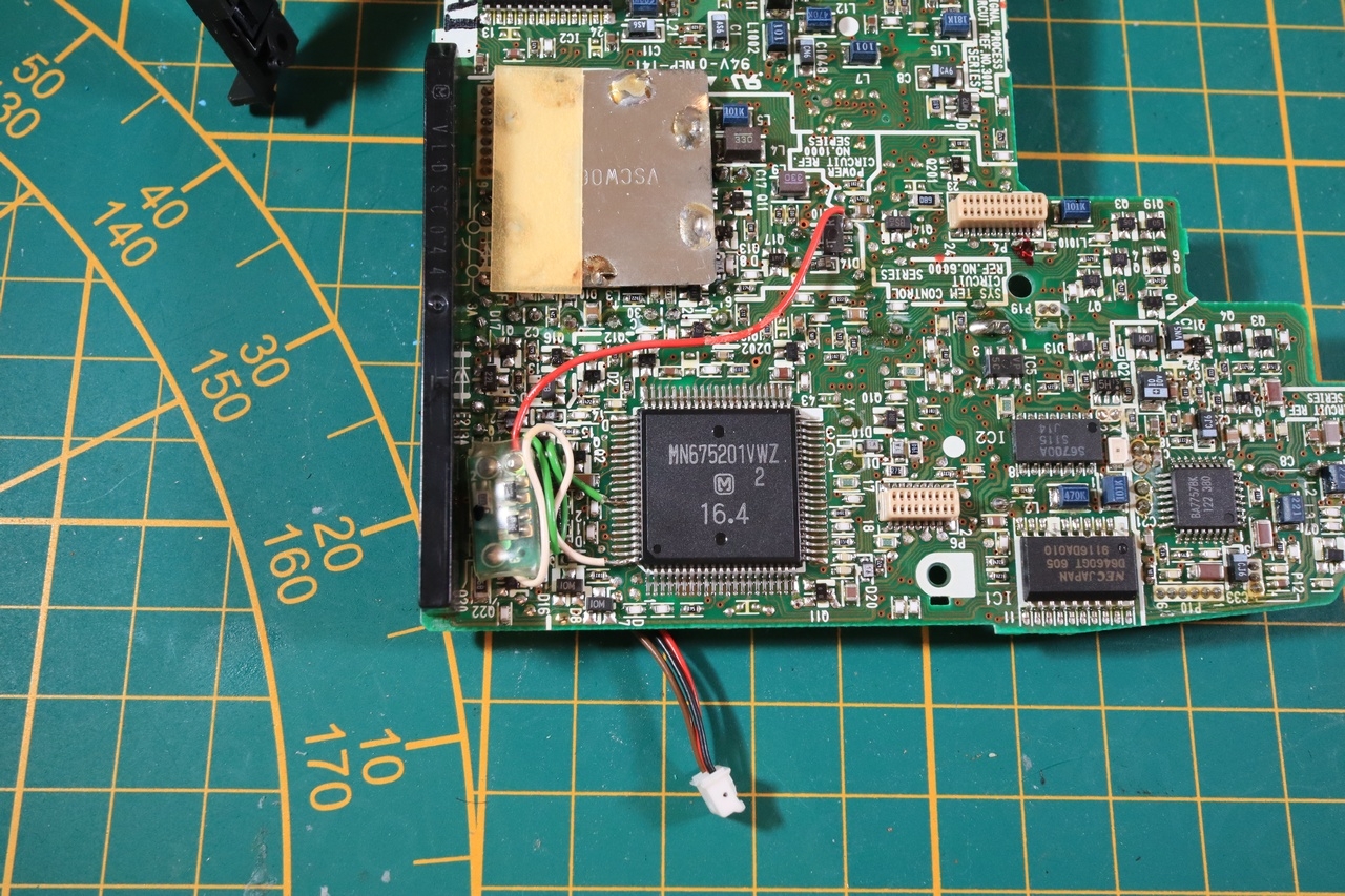
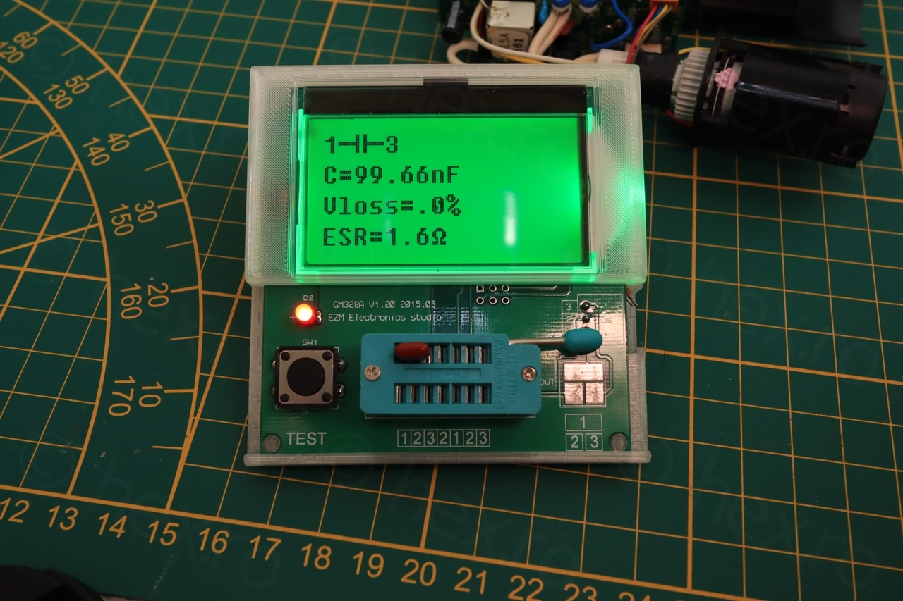
And it seems that the Panasonic driver board respected the suggestion! In the photo below, the small resistor under the XRA7148F (it is closer to pin 8 in the photo) is 15kΩ indeed and connected to PIN 6 and the glossy orange film capacitor is connected to PIN 7 measures exactly 100nF out of circuit

This was the first dilemma. Capacitor and resistor are according to the schematic, but somehow, there is a problem with the vertical stability of image!
I decided to parallel another 100nF cap, and surprise surprise, the image stabilized but got ‘squished’ on the top right of the screen. I don’t have a better photo to illustrate than a capture from a video:
With some trial and error, I found that paralleling 10nF with the existing 100nF produces an image that is not jumpy and that fills the whole screen! However, I felt something was still wrong. Why would 110nF work but not the 100nF that was recommended ? Messing up with the frequency seemed to fix the issue. But why was not working properly ?!
I decided to try to see what signal is on pin 7 of the XRA7148F using my Siglent 1104x-e:
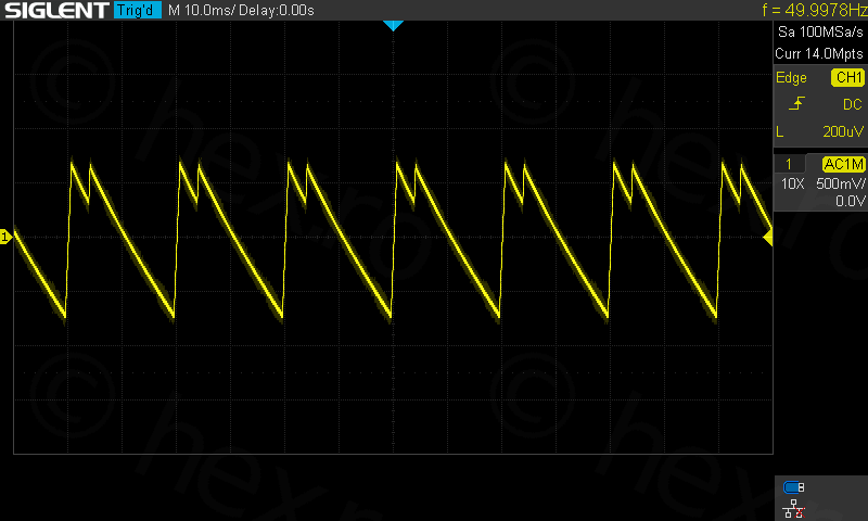
So this explains the jumpiness! Frequency was detected as 50Hz but there was the double peak.Curious how a good signal would look like, and after a lot of searching, I found the schematic of Sony CCD-TRV58 which is very nicely detailed and also contains the oscilloscope captures:
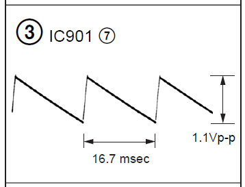
I decided to see what 16.7msec means in frequency, it means 60Hz. But wait! My oscilloscope was showing 50Hz ?! Going back to the BA7149F to try to clarify, I stumble onto this line “In PAL systems, change the value of the resistor connected between pin 6 and GND to 18kΩ.”. But the resistor was 15kΩ …
The driver boardwas designed for NTSC signal and not the European PAL.
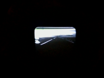
I switched Raspberry PI 3b+’s config.txt to sdtv_mode = 0 (or sdtv_mode=16 for progressive NTSC) and magic 🙂
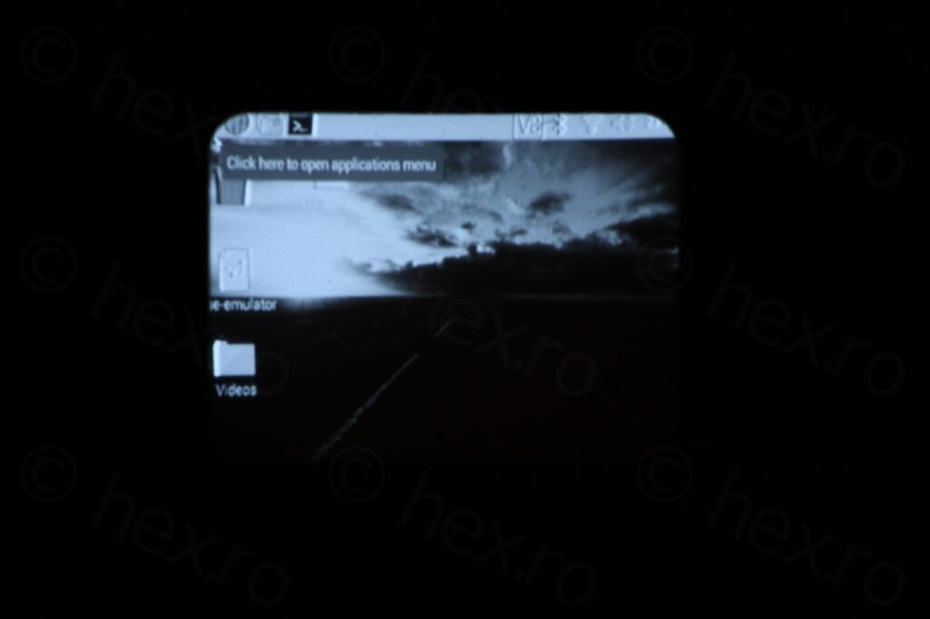
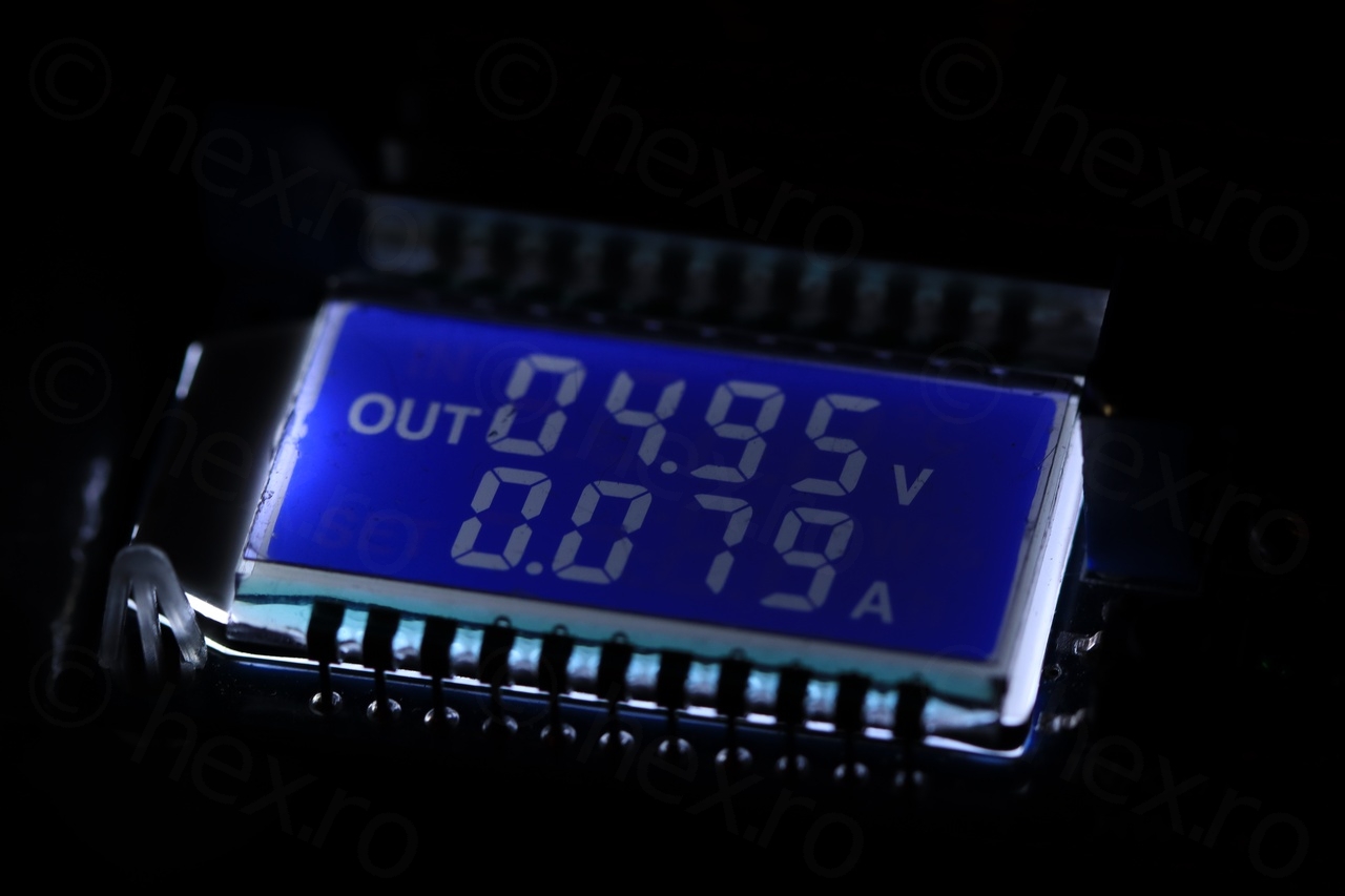
Results seem to indicate that the gray levels are a bit off, but I would expect this from such a tiny CRT. Board works at 5V and draws 80mA:
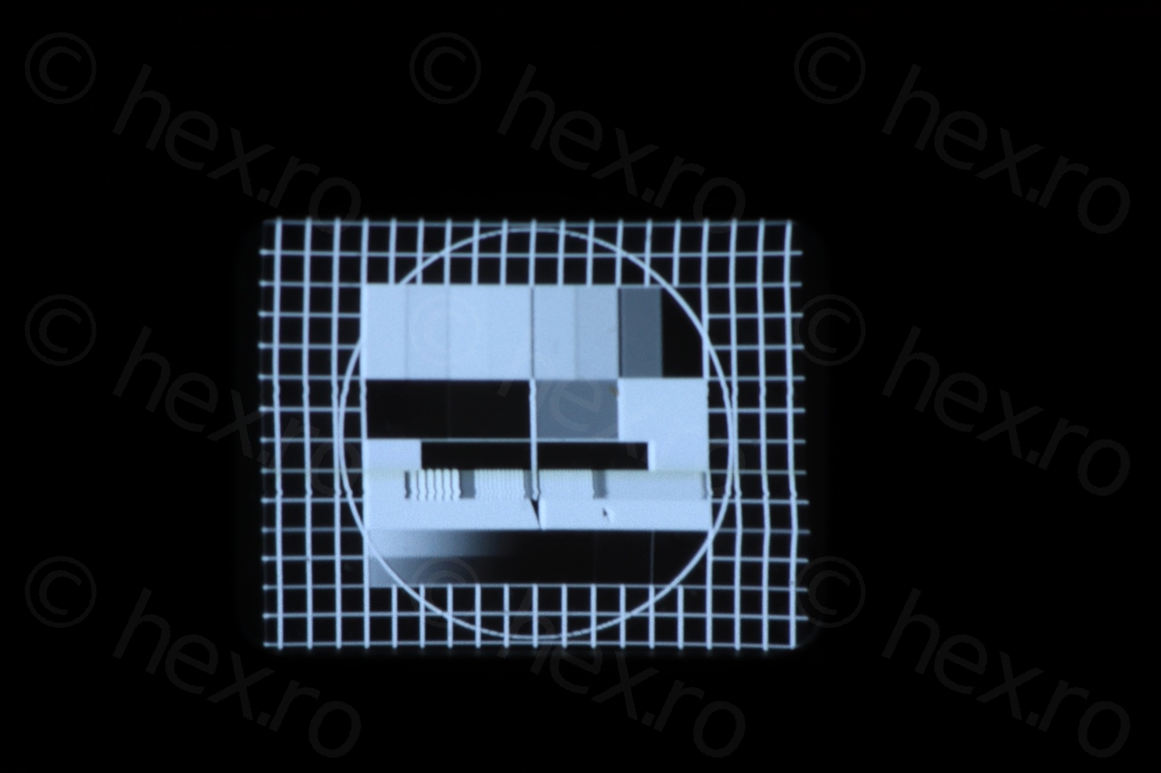
Few more images with the CRT itself before reassembly:


It does help to have an Oscilloscope instead of relying on voltage levels only. I did compare them with the Sony’s schematic voltages, almost identical. Happy I can move on to other cameras.
Andrew
wow, thanks for the info! you are a great fellow, I will be extremely grateful if you manage to connect a viewfinder from a panasonic nv vs70 camera!
Tehan
Hi! Out of curiosity, what do you do with all of those camcorder bags that you have gotten over the years when buying these camcorders ?
viulian
The bags get thrown away 🙂 since, to my surprise, they are very heavy compared to modern bags. Sometimes they are either rusted, torn away, dirty, etc.
Tehan
ohh
but aren’t they still useful (maybe for a new dslr cam)